

Page 1
S0037IVZ.fm
WIG 170 AC/DC
Betriebsanleitung. . . . . . . . . . . . . . . . . . . . .3
Operating Instruction . . . . . . . . . . . . . . . . . .9
Instructions d'utilisation . . . . . . . . . . . . . . .15
Handleiding . . . . . . . . . . . . . . . . . . . . . . . .21
Manuale d’istruzioni. . . . . . . . . . . . . . . . . .27
Manual de uso . . . . . . . . . . . . . . . . . . . . . .33
Betjeningsvejledning . . . . . . . . . . . . . . . . .39
Bruksanvisning . . . . . . . . . . . . . . . . . . . . .45
Bruksanvisning . . . . . . . . . . . . . . . . . . . . .51
115 168 8345 / 3805 - 3.0
Page 2

U2S0037.fm
2
Page 3
XS0018D.fm Betriebsanleitung DEUTSCH
,
Inhaltsverzeichnis
1. Zuerst lesen! ...............................3
2. Sicherheitshinweise ................... 3
2.1 Bestimmungsgemäße V
erwendung .................................... 3
2.2 Allgemeine Sicherheitshinweise ...3
2.3 Symbole auf dem Gerät................ 4
3. Bedienelemente ..........................4
4. Betriebsvorbereitung .................5
4.1 Aufstellen......................................5
4.2 Übrige Anschlüsse........................5
5. Bedienung ...................................5
5.1 Betriebsarten ................................5
5.2 Parameter.....................................6
5.3 Betrieb starten ..............................6
5.4 Betrieb beenden ...........................7
6. Wartung .......................................7
7. Lieferbares Zubehör..............7/59
8. Reparatur.....................................7
9. Umweltschutz..............................7
10. Störungen....................................7
11. Störungsbehebung.....................7
12. Technische Daten.......................8
− Zahlen in Abbildungen (1, 2, 3, ...)
− kennzeichnen Einzelteile;
− sind fortlaufend durchnumme-
− beziehen sich auf entspre-
− Handlungsanweisungen, bei denen
die Reihenfolge beachtet werden
muss, sind durchnummeriert.
− Handlungsanweisungen mit beliebiger Reihenfolge sind mit einem
Punkt gekennzeichnet.
− Auflistungen sind mit einem Strich
gekennzeichnet.
Stromschlaggefahr!
Warnung vor Personenschäden durch Elektrizität.
Achtung!
Warnung vor Sachschäden.
Hinweis:
Ergänzende Informationen.
riert;
chende Zahlen in Klammern (1),
(2), (3) ... im benachbarten Text.
DEUTSCH
heitshinweise, um Gefahren für Personen oder Sachschäden auszuschließen.
• Beachten Sie die speziellen Sicherheitshinweise in den jeweiligen
Kapiteln.
• Beachten Sie die gesetzlichen
Richtlinien oder UnfallverhütungsVorschriften für den Umgang mit
Lichtbogenschweißgeräten.
Gefahr!
B
Elektrische Spannung.
• Setzen Sie das Gerät nur in Innenräumen und in trockener Umgebung
ein.
• Schließen Sie das Gerät nur an eine
Stromquelle an, deren Schutzeinrichtungen einwandfrei funktionieren.
Wenden Sie sich im Zweifelsfall an
eine Elektrofachkraft!
• Reparaturen und Eingriffe in die
Geräte dürfen nur von ausgebildeten Elektrofachkräften durchgeführt
werden.
• Vor Öffnen des Gerätes müssen Sie
die Netzverbindung trennen.
1. Zuerst lesen!
Diese Betriebsanleitung wurde so
erstellt, dass Sie schnell und sicher mit
Ihrem Gerät arbeiten können. Hier ein
kleiner Wegweiser, wie Sie diese
Betriebsanleitung lesen sollten:
− Lesen Sie diese Betriebsanleitung
vor der Inbetriebnahme ganz durch.
Beachten Sie insbesondere die
Sicherheitshinweise.
− Diese Betriebsanleitung richtet sich
an ausgebildete Lichtbogenschweißer oder Fachkräfte mit ähnlicher
Qualifikation.
− Bewahren Sie alle mit diesem Gerät
gelieferten Unterlagen auf, damit
Sie sich bei Bedarf informieren können. Bewahren Sie den Kaufbeleg
für eventuelle Garantiefälle auf.
− Wenn Sie das Gerät einmal verleihen oder verkaufen, geben Sie alle
mitgelieferten Geräteunterlagen mit.
− Für Schäden, die entstehen, weil
diese Betriebsanleitung nicht beachtet wurde, übernimmt der Hersteller
keine Haftung.
Die Informationen in dieser Betriebsanleitung sind wie folgt gekennzeichnet:
Gefahr!
Warnung vor Personenschäden oder Umweltschäden.
2. Sicherheitshinweise
2.1 Bestimmungsgemäße
Verwendung
Das Schweißgerät ist bestimmt für das
Verschweißen aller Metalle.
Es entspricht bei Auslieferung den einschlägigen Bestimmungen.
Das Schweißgerät ist bestimmt für den
Gebrauch durch ausgebildete Lichtbogenschweißer oder Fachkräfte mit ähnlicher Qualifikation.
Zugelassene Schweißverfahren:
− WIG AC/DC (Wolfram-Inert-Gas),
für alle Metalle
− Elektrodenschweißen
Beim Schutzgasschweißverfahren ist
sicherzustellen, dass die Schutzglocke
des Schutzgases nicht durch Zugluft
weggeblasen wird.
Geräteleistungen siehe „Technische
Daten“.
Jede andere Verwendung gilt als
bestimmungswidrig und ist verboten.
Durch bestimmungswidrige Verwendung, Veränderungen am Gerät oder
durch den Gebrauch von Teilen, die
nicht vom Hersteller geprüft und freigegeben sind, können unvorhersehbare
Schäden entstehen!
2.2 Allgemeine Sicherheitshinweise
• Beachten Sie beim Gebrauch dieses Gerätes die folgenden Sicher-
A
Gefahr!
• Tragen Sie bei Schweißarbeiten
unbedingt ausreichende Schutzkleidung.
• Verwenden Sie unbedingt Schutzschild und Schutzhandschuhe.
Sie schützen sich dadurch vor Funkenflug und Lichtbogenstrahlung.
• Alle Metalldämpfe sind schädlich!
Sorgen Sie bei Arbeiten in geschlossenen Räumen immer für eine
ausreichende Belüftung und Absaugung, damit die maximalen Schadstoffkonzentrationen am Arbeitsplatz nicht überschritten werden.
Die Dämpfe von Blei, Cadmium,
Kupfer, Chrom, Nickel, Zink und
Beryllium sind besonders gefährlich!
Achtung!
A
• Schweißen Sie niemals ein
Schweißgut, das geerdet ist.
Sie vermeiden so eine eventuelle
Beschädigung der Schutzleiter
durch vagabundierende Schweißströme (Potentialverschleifungen).
• Benutzen Sie das Schweißgerät niemals zum Auftauen von Rohren.
• Befestigen Sie die Klemme der
Schweißstromrückleitung immer
direkt am Schweißgut und so nah
wie möglich an der Schweißstelle.
• Tragen Sie das Schweißgerät
immer am Tragegurt, wenn Sie es
transportieren.
3
Page 4
DEUTSCH
• Besondere Vorsicht ist geboten,
wenn Sie mit dem Gerät in der Nähe
von Computern, elektronisch
gesteuerten Anlagen oder in der
Nähe von magnetischen Datenträgern (Tonbänder, Disketten, Datenbändern, Scheckkarten o.ä.) arbeiten.
Bei der Lichtbogenzündung kann es
zu Fehlfunktionen der Anlagen oder
Datenverlusten kommen.
2.3 Symbole auf dem Gerät
Gefahr!
Missachtung der folgenden Warnungen kann zu
schweren Verletzungen
oder Sachschäden führen.
2-Takt-Funktion ohne HFZündung
4-Takt-Funktion ohne HFZündung
2-Takt-Funktion mit HFZündung
4-Takt-Funktion mit HFZündung
Lichtbogenschweißen mit
umhüllter Stabelektrode
und Arc-Force-Funktion
Gas-Nachströmzeit
Abfallzeit
Balance
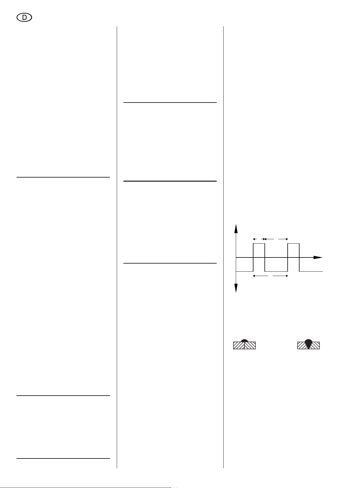
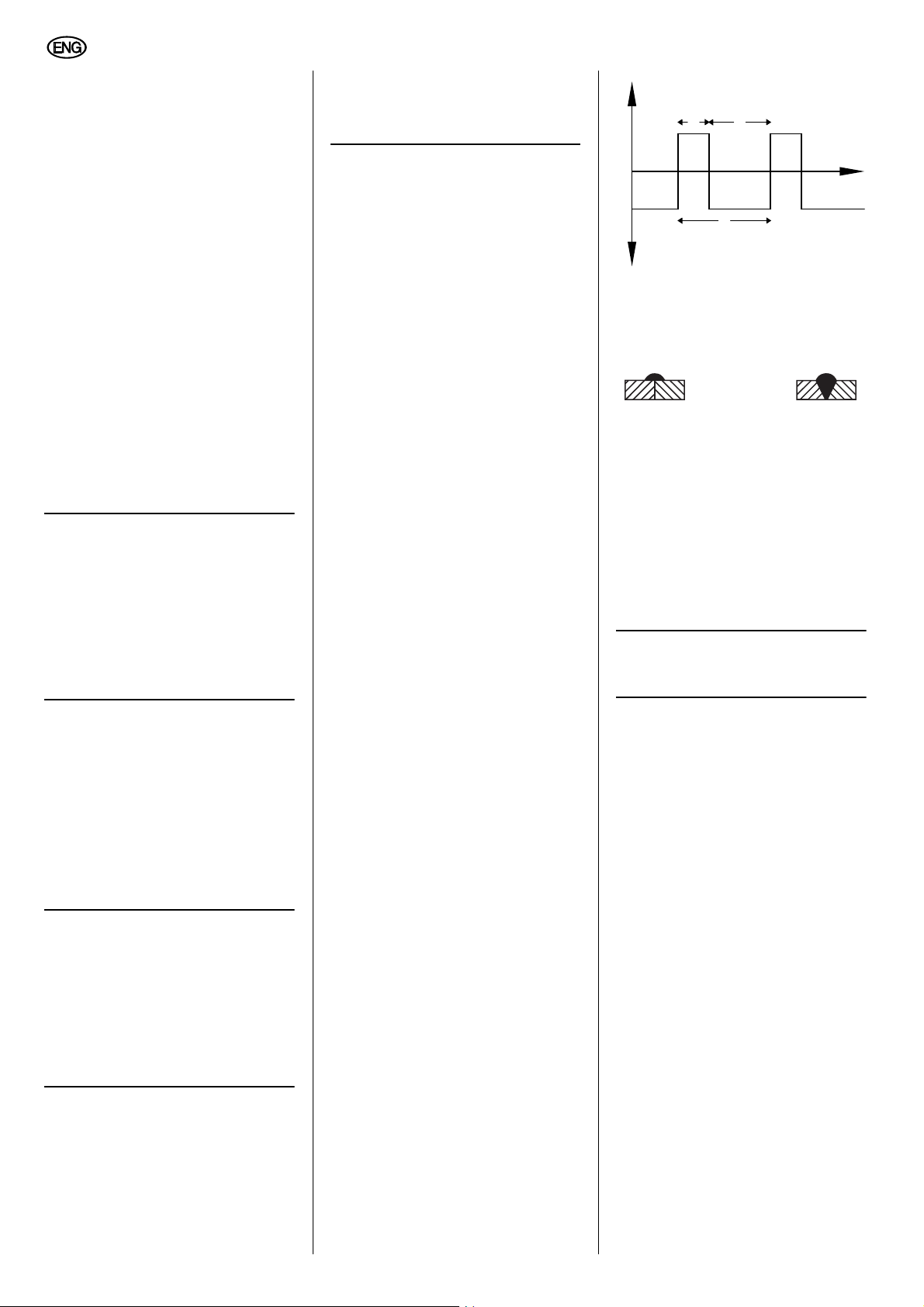
Geringere Reinigungswirkung
Höhere Reinigungswirkung
Netzspannung
S-Test
Übertemperatur
Anschluss für Fernregler
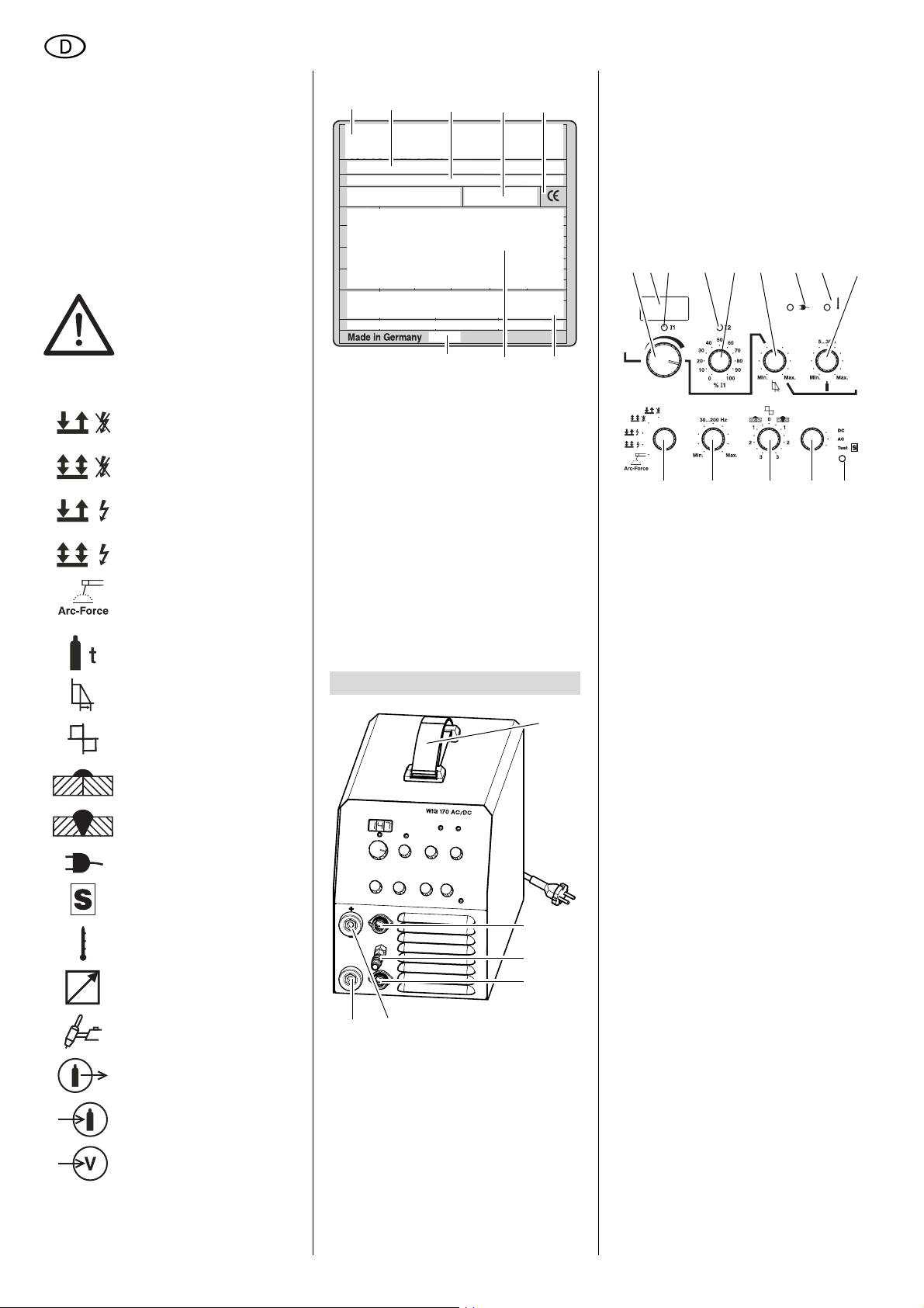
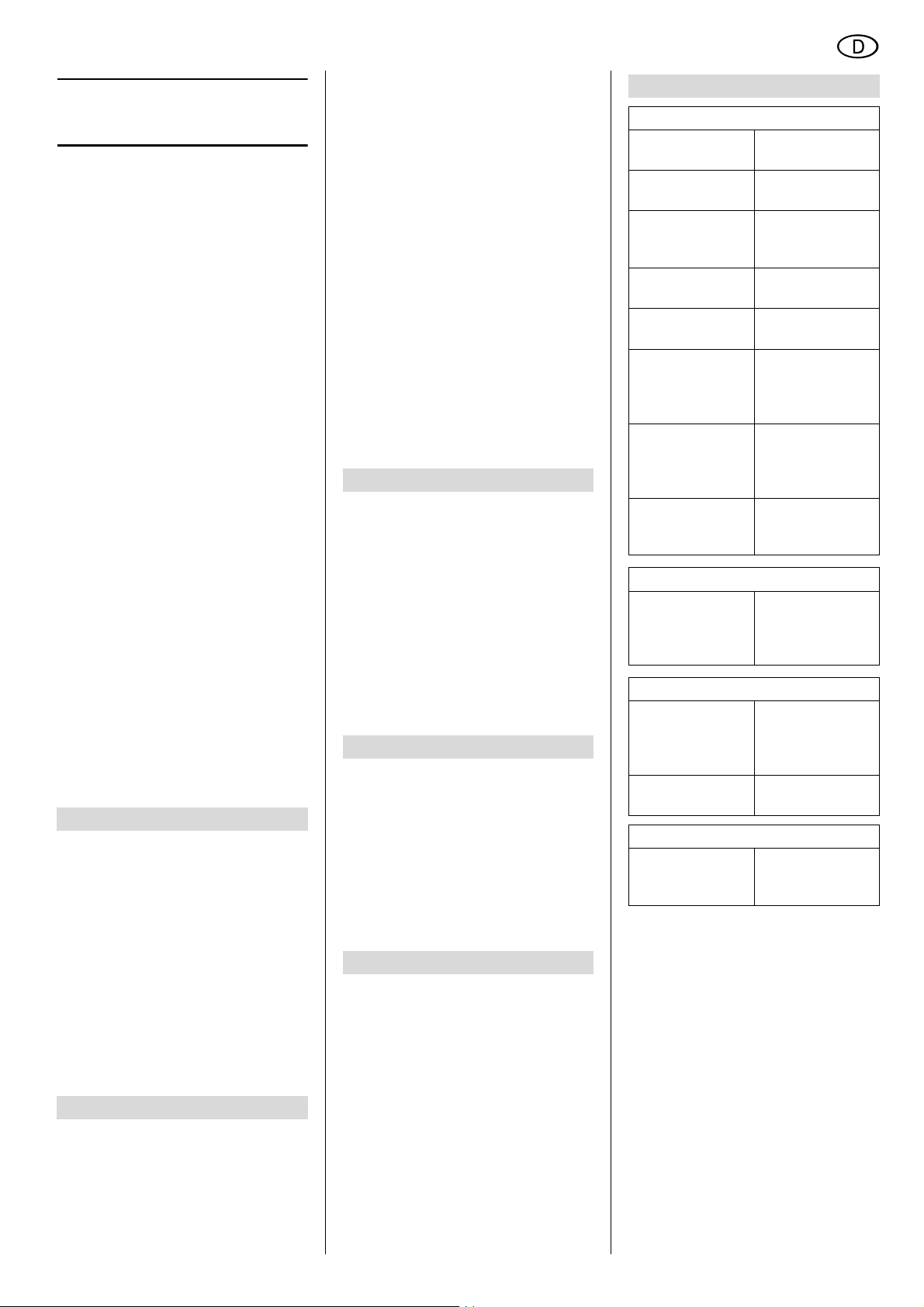
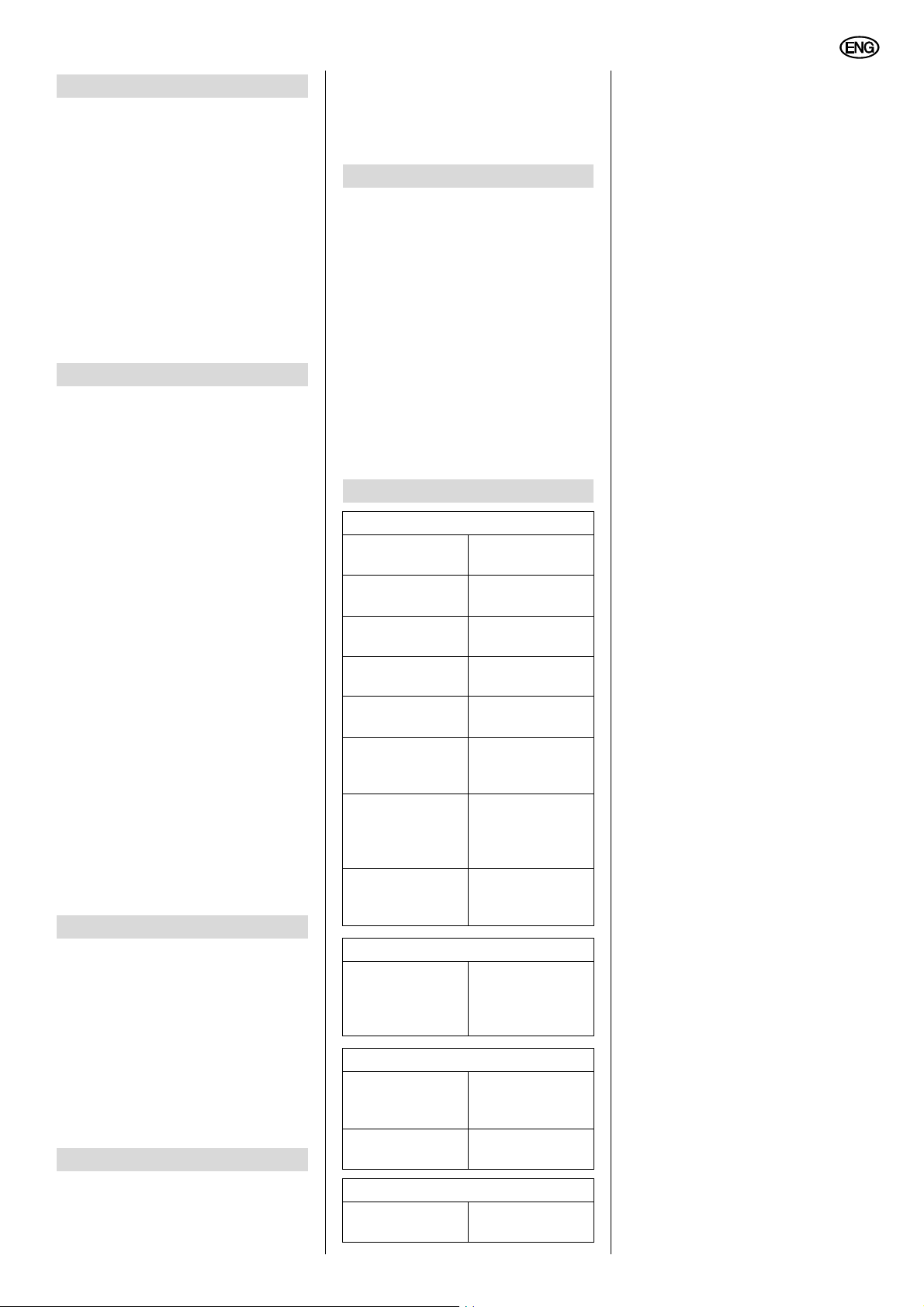
Angaben auf dem Leistungsschild:
1
2
1 Hersteller
2 Gerätebezeichnung
3 Seriennummer
4 Normenhinweis – Diese Gerät
erfüllt die Anforderungen der
genannten Norm
5 CE-Zeichen – Dieses Gerät
erfüllt die EU-Richtlinien gemäß
Konformitätserklärung
6 Entsorgungssymbol – Gerät kann
über Hersteller entsorgt werden
7 Elektrische Leistungsdaten
8 Baujahr
345
8
7
6
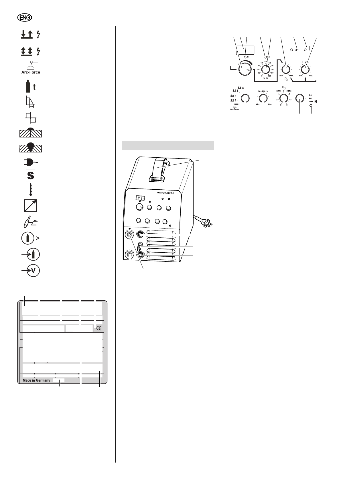
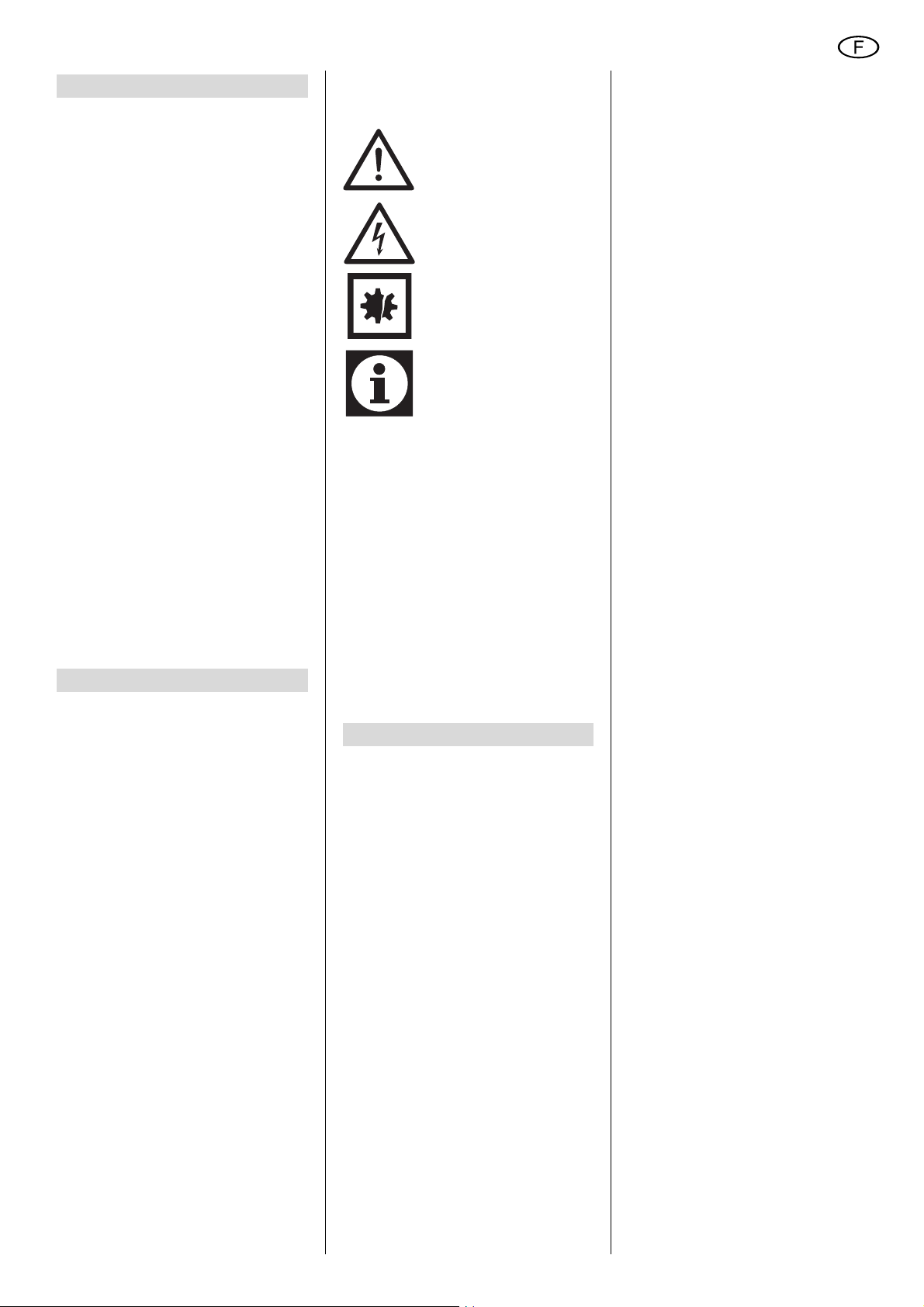
3. Bedienelemente
9
10
11
12
11 Anschluss für Brenner-Schutz-
gasleitung
12 Anschluss für Steuerleitung
WIG-Schweißbrenner
13 Anschluss Schweißstrom
(+ Pol)
14 Anschluss Schweißstrom (- Pol)
15 16 17 18 19 20 21 22 23
28
15 Schweißstromeinsteller
16 LED-Anzeige
zeigt den aktuell eingestellten
Schweißstrom.
17 Schweißstrom I1-Anzeige
− LED leuchtet:
Schweißstrom ist aktiv.
18 Zweitstrom I2-Anzeige
(nur in der Betriebsart 4-Takt)
− LED leuchtet:
Zweitstrom I2 ist aktiv.
19 Zweitstrom I2-Einsteller
20 Absenkzeiteinsteller
21 Betriebsabzeige
− LED leuchtet:
Gerät ist eingeschaltet und
es liegen keine Störungen
vor.
− LED aus:
Gerät ist ausgeschaltet,
oder es liegt eine Störung
vor.
2627
25
24
Anschluss für WIGSchweißbrenner
Gasanschluss für WIGSchweißbrenner
Anschluss für Gaszufuhr
Hauptschalter
14
13
9 Trage-/Schultergurt
In der Länge verstellbar zum
Transport
− an der Hand (wie in der
Abb. dargestellt).
− über der Schulter.
10 Anschluss für Fernregler
22 Übertemperaturanzeige
− LED leuchtet:
Die Übertemperatursicherung hat ausgelöst und die
Steuerung abgeschaltet.
23 Gasnachströmzeiteinsteller
4
Page 5

DEUTSCH
24 S-Testanzeige
− LED leuchtet:
Gerät ist betriebsbereit.
− LED ist aus:
S-Test hat ausgelöst, das
Gerät ist nicht betriebsbereit.
25 Umschalter Stromart
26 Balanceeinsteller
27 Frequenzeinsteller
28 Umschalter Betriebsart
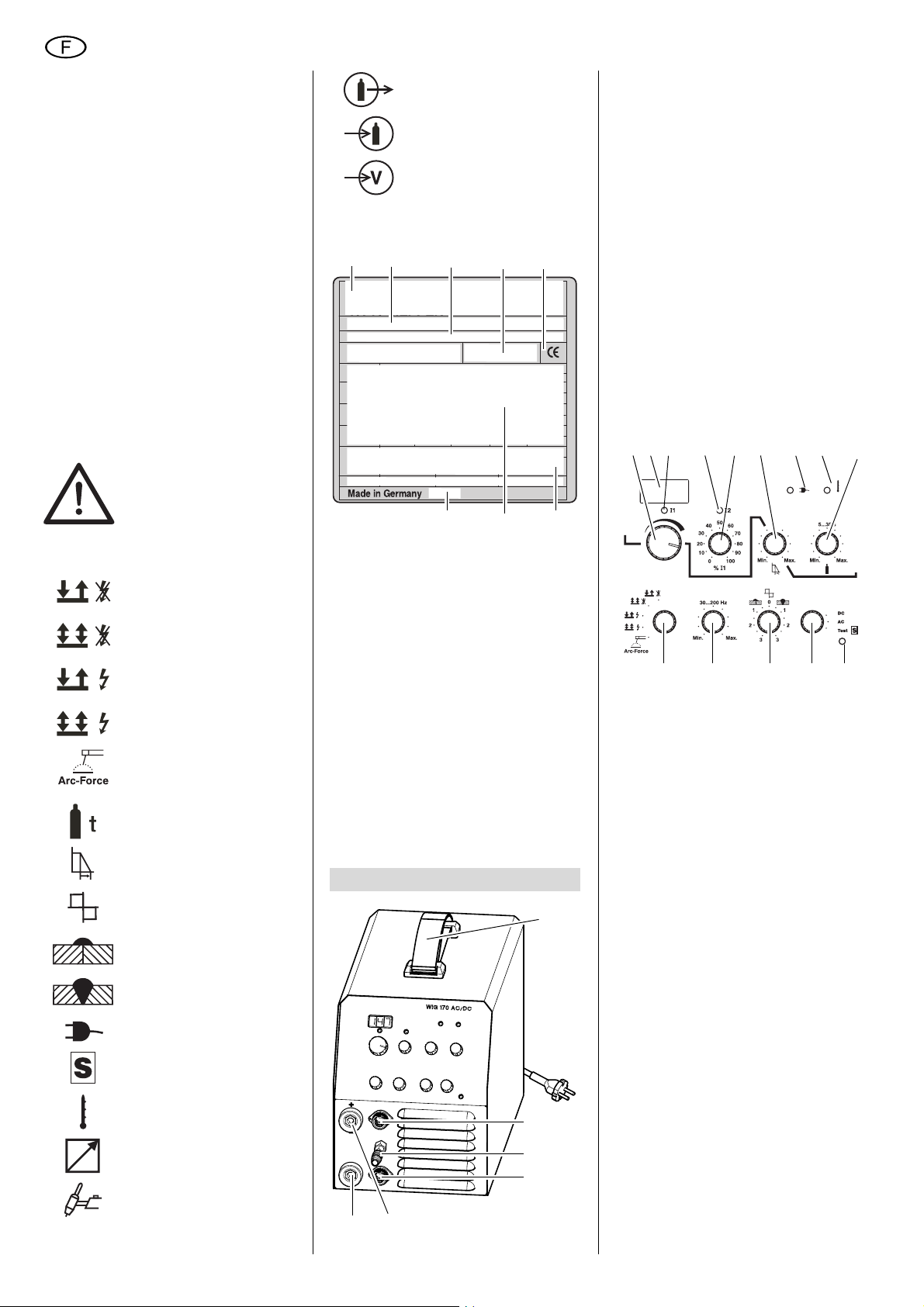
29
30
31
29 Hauptschalter
schaltet das Gerät ein oder aus.
30 Anschluss für Gaszufuhr
31 Netzanschlusskabel
LED = Licht-Emittierende Diode,
dient als Kontrolleuchte.
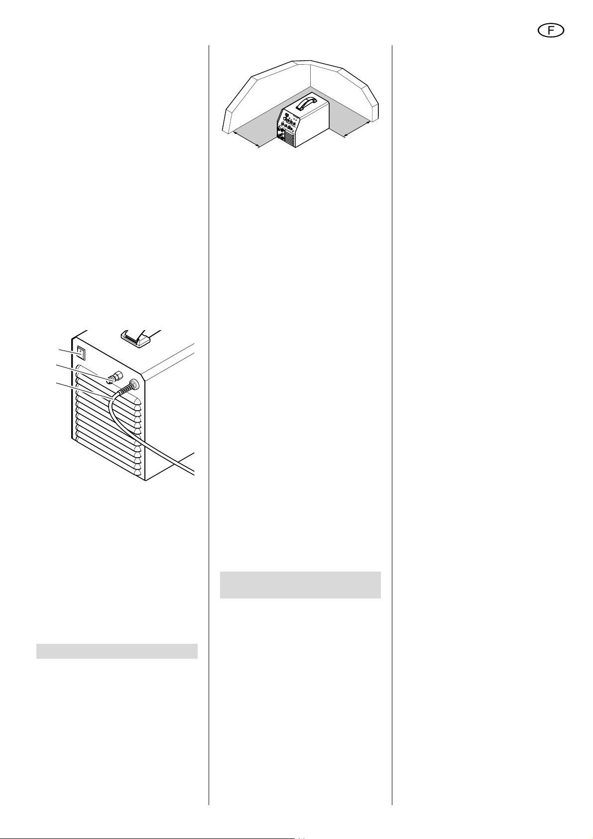
4. Betriebsvorbereitung
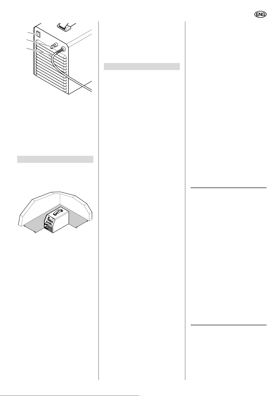
4.1 Aufstellen
Achtung!
A
Stellen Sie das Gerät immer
nur auf den Gerätefüßen ab.
>20 cm
Das Gerät saugt an der Frontseite
und am Boden Luft an und gibt sie an
der Rückseite durch die Lüftungsschlitze wieder ab. Achten Sie unbedingt auf einen ungehinderten Luft-
>20 cm
strom. Der Abstand des Gerätes zu
Wänden oder anderen Geräten muss
mindestens 20 cm betragen.
4.2 Übrige Anschlüsse
Achtung!
A
Beachten Sie beim Anschluss
der Schweißstromleitungen die geforderte Polarität für das gewünschte
Schweißverfahren und die verwendeten Elektroden.
Elektrodenschweißen
Vor der ersten Inbetriebnahme:
1. Schweißstromrückleitung am -Pol
anschließen.
2. Schweißleitung am +Pol anschlie-
ßen.
Schutzgasschweißen
Vor der ersten Inbetriebnahme:
1. Gewebedruckschlauch an Druck-
minderer anschließen.
2. Schweißstromrückleitung am +Pol
anschließen.
3. Schweißstrom WIG-Schweißbren-
ner am -Pol anschließen.
4. Steuerleitung WIG-Schweißbrenner
anschließen.
5. Gasleitung vom WIG-Schweißbren-
ner anschließen.
5. Bedienung
Sämtliche Gerätefunktionen steuern Sie
mit den Schaltern und Einstellern an der
Frontplatte.
Nach dem Einschalten leuchten alle
LEDs einmal kurz auf. In der LEDAnzeige erscheint:
− für ca. 2 Sekunden die SoftwareVersion (blinkend), danach
− für ca. 1 Sekunde die gewählte Konfiguration, und
− der aktuell eingestellte Schweißstrom.
Voraussetzung:
Der Selbsttest war fehlerfrei (die
Betriebsanzeige und die LED S-Test
leuchten).
5.1 Betriebsarten
Wählen Sie mit dem Umschalter
Betriebsart eine der möglichen Betriebsarten aus:
2T
Betriebsart für das WIG-Schweißen im
2 Takt-Betrieb:
1. Werkstück mit Wolframelektrode
berühren.
2. Start-/Stopp-Taster am WIGSchweißbrenner betätigen.
− Die LED Schweißstrom I1 leuch-
tet.
− Schweißprozess startet mit dem
fest eingestellten Startstrom.
− Nach erfolgter Zündung steigt der
Schweißstrom auf den eingestellten Betriebsstrom an.
3. Start-/Stopp-Taster loslassen.
− Der Schweißprozess endet.
− Die eingestellte Gasnachström-
zeit läuft.
4T
Betriebsart für das WIG-Schweißen im
4-Takt-Betrieb:
1. Werkstück mit Wolframelektrode
berühren.
2. Start-/Stopp-Taster am WIGSchweißbrenner betätigen.
− Die LED Schweißstrom I1 leuch-
tet.
− Der Schweißprozess startet.
− Solange der Start-/Stopp-Taster
gedrückt ist, brennt der Lichtbogen mit dem fest eingestellten
Startstrom.
− Nach dem Loslassen steigt der
Strom auf den eingestellten
Betriebsstrom an.
3. Zweitstromtaster am WIG-Schweißbrenner drücken (bei Bedarf).
Solange der Zweitstromtaster
gedrückt ist:
− brennt der Lichtbogen mit dem
eingestellten Zweitstrom I2.
− leuchtet die LED Zweitstrom I2.
4. Start-/Stopp-Taster nochmals betätigen.
Schweißstrom sinkt in der eingestellten Abfallzeit auf den Minimalstrom ab.
− Solange der Taster gedrückt ist,
brennt der Lichtbogen mit dem
Minimalstrom weiter (Endkraterfüllung).
− Nach dem Loslassen endet der
Schweißprozess.
2T + HF
Betriebsart für das WIG-Schweißen im
2 Takt-Betrieb, allerdings mit HF-Zündung. Die Zündung erfolgt, ohne dass
die Wolframelektrode das Wekstück
berührt.
4T + HF
Betriebsart für das WIG-Schweißen im
4 Takt-Betrieb, allerdings mit HF-Zündung. Die Zündung erfolgt, ohne das die
Wolframelektrode das Wekstück berührt.
Elektrode
Betriebsart für das Elektrodenschweißen. Die LED Schweißstrom I1 leuchtet.
Hinweis:
3
Das Gerät verwendet beim Elektrodenschweißen immer die folgenden
Funktionen:
5
Page 6
DEUTSCH
Hot-Start
− Bei Berührung des Werkstücks mit
der Elektrode wird der eingestellte
Schweißstrom für kurze Zeit erhöht,
um ein sicheres Zünden des Lichtbogens zu erreichen.
Die kurzfristige Erhöhung des
Schweißstromes ist auf den maximalen Elektrodenstrom begrenzt.
Arc-Force
− Während des Schweißprozesses
hält das Gerät die Energie (Wärme)
konstant, die in das Material eingebracht wird, auch wenn sich der
Abstand der Elektrode zum
Schweißbad ändert.
Anti-Stick
− Erkennt das Gerät einen Kurzschluss im Schweißprozess, wird
nach 0,5 Sekunden auf Minimalstrom geschaltet, um ein Ausglühen
der Elektrode zu verhindern.
Mit dem Umschalter Stromart bestimmen Sie die verwendete Schweißstromart.
DC
Das Gerät liefert Gleichstrom.
AC
Das Gerät liefert Wechselstrom.
S-Test
Das Gerät prüft die internen Sicherheiteinrichtungen zum Arbeiten unter erhöhter elektrischer Gefährdung. Um den
Test zu starten:
1. Gerät einschalten
Die Betriebsanzeige und die LED
S-Test müssen leuchten.
2. Umschalter Stromart auf „Test“
schalten.
− Das Gerät simuliert intern einen
Fehler am Schweißstromausgang. Die LED S-Test muss
nach kurzer Zeit erlöschen.
− Wenn die LED S-Test erlischt,
war der Test erfolgreich.
Das Gerät ist jetzt nicht mehr
betriebsbereit!
3. Gerät ausschalten.
4. Wahlschalter auf die gewünschte
Stromart zurückschalten und nach
ca. 10 Sek. wieder einschalten.
Hinweis:
3
Erfolgreicher Test bedeutet, dass
kein Fehler in der Sicherheitseinrichtung erkannt wurde.
Nicht erfolgreicher Test bedeutet, dass
die Steuerung einen Fehler in der
Sicherheitseinrichtung erkannt hat.
Stellen Sie in diesem Fall die Arbeiten
ein und wenden sich an den Service!
5.2 Parameter
Die folgenden Parameter können Sie
variieren:
Schweißstrom I1
Maximaler Strom für den eigentlichen
Schweißprozess.
Einstellbereich, in 1 A-Schritten,
− beim WIG-Schweißen: 3 A…170 A
− beim Elektrodenschweißen:
10 A…140 A.
Hinweis:
3
Während des Schweißprozesses
wird der aktuelle Sollwert des Schweißstromes angezeigt.
Haben Sie eine Absenkzeit größer Null
eingestellt, ändert sich der Wert in der
Anzeige kontinuierlich, bis der Endwert
erreicht ist.
Eine Änderung des Schweißstromes
während des Schweißprozesses ist
jederzeit möglich.
Hinweis:
3
Ist ein Fußfernregler an dem
Gerät angeschlossen, schaltet das
Gerät generell in den Zwei-Takt-Betrieb.
Ist ein Handfernregler angeschlossen,
kann der Betriebsstrom nur mit diesem
Regler variiert werden.
Stromeinstellbereich Fußfernregler:
Minimalstrom bis eingestellter Betriebsstrom.
Stromeinstellbereich Handfernregler:
Minimalstrom bis Maximalstrom.
Zweitstrom I2
Strom, auf den während des Schweißprozesses im 4-Takt-Betrieb umgeschaltet werden kann. Um den aktuell eingestellten Wert anzuzeigen:
1. Eine 4-Takt-Betriebsart einstellen.
2. Zweitstromtaster am WIG-Schweiß-
brenner drücken und gedrückt halten.
− Die LED Schweißstrom I2 leuchtet, und in der Anzeige erscheint
der aktuell eingestellte Wert von
I2. Der Wert kann jetzt mit dem
Zweitstromeinsteller variiert werden.
3. Zweitstromtaster loslassen.
− LED Schweißstrom I2 erlischt, in
der Anzeige erscheint wieder der
Wert des Schweißstromes I1.
− Der eingestellte Wert für I2 wird
gespeichert.
Minimalstrom
Strom, auf den der Schweißstrom am
Ende des Schweißprozesses zur Endkraterfüllung absinkt.
Absenkzeit
Zeitdauer, in der der Strom auf den Minimalstrom abfällt.
Einstellbereich: Min.…Max., gleichbedeutend 5 ms…10 sec.
Gasnachströmzeit t.
Zeitdauer, für die das Schutzgas nachströmt, nachdem der Schweißprozess
beendet wurde.
Einstellbereich 5…35 sec.
FREQUENZ
Frequenz der Schweißimpulse.
Mit der Formel 1 ÷ eingestellte
Frequenz [Hz] = Zeitdauer [sec] können
Sie die Zeitdauer eines Impulses errechnen.
Einstellbereich: 30 Hz…200 Hz.
BALANCE
(nur in der Betriebsart WIG AC...)
Verhältnis von Zeitdauer positiver Spannung zu Zeitdauer negativer Spannung
beim AC-Schweißen. Ein Wert von beispielsweise 30 % bedeutet, dass für
30 % der Zeitdauer (t
die Schweißspannung an der Elektrode
positiv, und für 70 % der Zeitdauer (t
negativ ist.
) einer Periode (T)
1
+U
t
t
1
2
T
-U
Eine Erhöhung dieses Wertes bewirkt
eine höhere Reinigungswirkung (Aluminiumschweißen), hat aber gleichzeitig
eine höhere thermische Belastung der
Elektrode zur Folge.
Einstellbereich:
25 % … 75 %.
5.3 Betrieb starten
Schutzgasschweißen
Achtung!
A
Vor Beginn der Arbeit prüfen:
− Richtiges Schutzgas angeschlossen?
− Richtige Brennerdüse eingesetzt?
− Elektrode noch spitz genug?
Schleifen Sie bei Bedarf die Elektrode nach.
)
2
t
6
Page 7
DEUTSCH
Hinweis:
3
Elektroden für das DC-Schwei-
ßen nur in Längsrichtung anschleifen!
1. Schweißstromrückleitung an geeigneter Stelle am Werkstück befestigen.
2. Hauptabsperrventil an Gasflasche
öffnen und gewünschte Gasmenge
einstellen.
Bei Bedarf Gasdüse wechseln.
3. Hauptschalter einschalten.
4. Gewünschtes Schweißverfahren
wählen.
5. Gewünschten Schweißstrom einstellen.
Das Schweißgerät ist jetzt betriebsbereit.
Elektrodenschweißen
1. Schweißstromrückleitung an geeigneter Stelle am Werkstück befestigen.
2. Hauptschalter einschalten.
3. Schweißverfahren „Elektrode“ wählen.
4. Gewünschten Schweißstrom einstellen.
Das Schweißgerät ist jetzt betriebsbereit.
5.4 Betrieb beenden
1. Hauptabsperrventil an Gasflasche
schließen.
2. Hauptschalter auf „0“ stellen.
3. Verbindung der Schweißstromrückleitung zum Werkstück trennen.
4. Netzstecker ziehen.
6. Wartung
Das Schweißgerät ist weitgehend wartungsfrei.
Je nach Staubbelastung sollte es alle 4
bis 6 Monate mit trockener und ölfreier
Druckluft ausgeblasen werden.
Zum Öffnen des Schweißgerätes entfernen Sie die Gehäuseschrauben und
schieben das Gehäuseoberteil nach hinten.
Überprüfen Sie in regelmäßigen Abständen das Gerät auf sichtbare Mängel.
Benachrichtigen Sie bei Schäden an den
Kabeln eine Elektrofachkraft.
7. Lieferbares Zubehör
Für die Geräte WIG 170 AC/DC empfehlen wir das nachfolgend genannte Zubehör. Dieses Zubehör ist mit dem Gerät
getestet worden und garantiert ein problemloses Arbeiten.
A WIG-Schweißbrenner Mistral,
1) mit 4 m Anschlusslänge
2) mit 8 m Anschlusslänge
B Druckminderer mit 2 Manometern
1) ohne Absperrventil
2) mit Absperrventil
C Fuß-Fernregler
zur stufenlosen Schweißstromregulierung.
1) mit 5 m Kabel, Kunststoffgehäuse
2) mit 5 m Kabel, Alugehäuse
3) mit 10 m Kabel, Alugehäuse
D Hand-Fernregler
zur stufenlosen Schweißstromregulierung,
1) mit 5 m Kabel
2) mit 10 m Kabel
E Massekabel, 25 mm
F Schweißkabel, 16 mm
G Schweißschild
1) als Kopfhaube
2) Automatik-Schutzschirm
2
, 3 m
2
, 3 m
8. Reparatur
Gefahr!
A
Reparaturen an Elektrowerkzeugen dürfen nur durch eine Elektrofachkraft ausgeführt werden!
Reparaturbedürftige Schweißgeräte
können an die Service-Niederlassung
Ihres Landes eingesandt werden. Die
Adresse finden Sie bei der Ersatzteilliste.
Bitte beschreiben Sie bei der Einsendung zur Reparatur den festgestellten
Fehler.
9. Umweltschutz
Das Verpackungsmaterial der Maschine
ist zu 100 % recyclingfähig.
Ausgediente Elektrowerkzeuge und
Zubehör enthalten große Mengen wertvoller Roh- und Kunststoffe, die ebenfalls einem Recyclingprozess zugeführt
werden können.
Die Anleitung wurde auf chlorfrei
gebleichtem Papier gedruckt.
10. Störungen
Im Störungsfall erscheinen in der LEDAnzeige drei Balken (---).
Gleichzeitig erlischt die LED Betriebsanzeige.
Übertemperatur
Die Übertemperaturanzeige leuchtet.
− Lassen Sie das Gerät eingeschaltet.
So kann der Lüfter das Gerät
schneller abkühlen.
− Der Betriebsstrom wird wieder
angezeigt, wenn die Temperatur auf
normale Werte abgesunken ist.
Sie können jetzt weiterarbeiten.
11. Störungsbehebung
Spröde oder poröse Schweißnaht
Gashahn
geschlossen?
Leere Gasflasche?
Ungeeignetes
Schutzgas?
Gasschlauchanschlüsse undicht?
Druckminderer
defekt?
Gasdüse am
Brenner oder
Schlauchpaket
verstopft?
Zugluft an der
Schweißstelle?
Unsauberes
Werkstück?
Ständiger Gasaustritt
Magnetventil
defekt oder verschmutzt?
Kein Schweißstrom
Schweißstromrückleitung gibt
keinen richtigen
Kontakt?
Steuerplatine
defekt?
Keine Funktion des Gerätes
Netzsicherung
ausgelöst?
Gashahn öffnen.
Gasflasche tauschen.
Geeignetes
Schutzgas verwenden.
Anschlüsse überprüfen.
Druckminderer
überprüfen.
Gasdüse reinigen.
Schweißstelle
abschirmen bzw.
Gasdurchfluss
erhöhen.
Rost, Fett oder
Lackschicht entfernen.
Magnetventil von
Elektrofachkraft
überprüfen lassen.
Schweißstromrückleitung auf
richtigen Kontakt
prüfen.
Service
informieren.
Netzsicherung
einschalten oder
wechseln.
7
Page 8

DEUTSCH
12. Technische Daten
Gerät WIG 170 AC/DC
Netzanschlussspannung: 230 V (+15 %/-15 %) / 50 - 60 Hz
Leerlaufspannung: V 85
Arbeitsspannung WIG: V 10,12 - 16,8
Arbeitsspannung Elektrode: V 20,4 - 25,6
Stromeinstellbereich, WIG: A 3 - 170 A
Stromeinstellbereich, Elektrode: A 10 - 140 A
Eingangsleistung max., WIG: kVA 4,8
Eingangsleistung max., Elektrode: kVA 5,5
Eingangshöchststrom, WIG: A 21
Eingangshöchststrom, Elektrode: A 24
Max. Einschaltdauer WIG 40 °C: % 40
Max. Einschaltdauer E 40 °C: % 40
60% Einschaltdauer WIG 40 °C: A 140
60% Einschaltdauer E 40 °C: A 100
100% Einschaltdauer WIG 40 °C : A 110
100% Einschaltdauer E 40 °C : A 80
Schutzart: IP23C
Verschweißbare Elektroden: Ø mm 2,5
Kühlart: F
Netzsicherung: T16A
Maße L x B x H: mm 480 x 260 x 320
Gewicht: kg 22,1
8
Page 9

XS0018E.fm Operating Instruction ENGLISH
ENGLISH
Table of Contents
1. Please Read First!....................... 9
2. Safety Information ......................9
2.1 Specified conditions of use........... 9
2.2 General safety information............9
2.3 Symbols on the machine ..............9
3. Operating Elements..................10
4. Preparing for Operation ...........11
4.1 Placing the machine ...................11
4.2 Other connectors ........................11
5. Operation...................................11
5.1 Operating modes ........................11
5.2 Parameters .................................12
5.3 Starting up ..................................12
5.4 Shutting down.............................12
6. Maintenance..............................13
7. Available Accessories.........13/59
8. Repairs.......................................13
9. Environmental Protection........13
10. Faults .........................................13
11. Trouble Shooting......................13
12. Technical Specifications..........14
1. Please Read First!
These instructions are written in a way
that will enable you to safely use the
equipment in a minimum of time. Here is
how to read the instructions:
− Read these instructions completely
before use. Pay special attention to
the safety information.
− These instructions are intended for
skilled arc welders or other specialists of similar qualification.
− Keep all documents supplied with
the machine for future reference.
Retain proof of purchase for possible warranty claims.
− If you hire out or sell this machine be
sure to hand over all documents
supplied with the machine.
− The equipment manufacturer is not
liable for any damage arising from
disregard of these instructions.
The information in these instructions is
marked as under:
Danger!
Warning of personal
injury or environmental
damage.
Risk of electric shock!
Risk of personal injury
by electric shock.
Caution!
Risk of material damage
Note:
Supplementary information.
− Numbers in illustrations (1, 2, 3, ...)
− indicate component parts;
− are consecutively numbered;
− refer to the corresponding num-
bers in brackets (1), (2), (3) ... in
the neighbouring text.
− Instructions to be carried out in
sequence are numbered.
− Instructions which can be carried
out in any sequence are preceded
by a bullet (•).
− Listing are preceded by a M-dash (–).
2. Safety Information
2.1 Specified conditions of
use
This welding machine is intended for
welding metals.
It conforms to all relevant regulations at
the time of delivery.
This welding machine is intended for
operation by professional arc welders or
specialists with similar qualifications.
Permissible welding processes:
− TIG AC/DC (Tungsten Inert Gas),
for all metals
− Stick electrode welding
For TIG welding it must be ensured that
the shielding gas cover is not blown
away by air draft.
For machine performance see “Technical Specifications”.
Any other use is not as specified and
prohibited.
Unspecified use, modification of the
machine or use of parts not tested and
approved by the equipment manufacturer could cause unforeseeable damage or even injury.
2.2 General safety information
• When using this machine, observe
the following safety instructions to
exclude the risk of personal injury or
material damage.
• Follow the specific safety instructions in the respective chapters.
• Follow all legal directives or regulations for the prevention of accidents
pertaining to the handling of arc
welding machines.
Danger!
B
Electric potential!
• Use machine indoors and in dry
environment only.
• Connect machine only to a properly
earthed outlet.
If in doubt check with a qualified
electrician!
• Service and repairs to the machines
must only be made by qualified electricians.
• Unplug before removing the
machine's cover.
A
Danger!
• Wear sufficient protective clothing
when welding.
• Always use a welding shield or helmet and welder's gloves.
They provide protection against
sparks and arc radiation.
• All metal fumes are detrimental to
health!
When working indoors ensure sufficient ventilation and extraction in
order to not exceed the max. permissible workplace pollutant concentration.
The fumes of lead, cadmium, copper, chromium, nickel, zinc and
beryllium are particularly harmful!
Caution!
A
• Never weld earthed metal.
This will prevent possible damage to
the protective earth conductors by
stray welding currents.
• Never use the welding machine for
thawing pipes.
• Always attach the welding return
cable directly to the workpiece and
as close as possible to the welding
spot.
• Always carry the welding machine at
the carrying strap when transporting it.
• Special care is required when working near computers, electronically
controlled equipment or in the proximity of magnetic data media (sound
recording tapes, floppy disks, data
recording tapes, credit cards, etc.).
The arc start can cause misfunction
of this type of equipment or data
loss.
2.3 Symbols on the machine
Danger!
Disregard of the following
warnings could cause
severe personal injury or
material damage.
2-step mode without HFignition
4-step mode without HFignition
9
Page 10
ENGLISH
2-step mode with HF-ignition
4-step mode with HF-ignition
Stick elevtrode welding and
Arc-Force function
Gas postflow time
Downslope time
Balance
Reduced cleaning action
Increased cleaning action
Mains voltage
S-Test
Excess temperature
Connector for remote control unit
Connector for TIG torch
1 Manufacturer
2 Machine designation
3 Serial number
4 Standard information – This
machine meets the requirements
of the standards mentioned
5 CE mark – This machine con-
forms to EC directives as per
declaration of conformity
6 Waste disposal symbol – the
machine can be disposed of
through the manufacturer
7 Electrical performance data
8 Date of manufacture
3. Operating Elements
15 16 17 18 19 20 21 22 23
28
15 Welding current control
16 LED display
Displays the currently set welding current.
9
17 I1 welding current indicator
− LED illuminated:
welding current active.
18 I2 secondary current indicator
(4-step mode only)
− LED illuminated:
secondary current I2 is
active.
2627
25
24
Connector for TIG torch gas
hose
Connector for gas supply
Main switch
Information on the name plate:
1
2
345
8
7
10
11
12
14
13
9 Carrying strap/shoulder strap
Adjustable in length for carrying
− by hand (shown in illustration)
− on the shoulder.
10 Connector for remote control
unit
11 Connector for torch gas hose
12 Connector for TIG torch
pilot lead
13 Welding current connector
(+ pole)
6
14 Welding current connector
(- pole)
19 I2 secondary current control
20 Downslope time control
21 Equipment-on indicator
− LED illuminated:
Machine is turned on, no
faults detected.
− LED off:
Machine turned off or fault
present.
22 Excess temperature indicator
− LED illuminated:
Excess temperature fuse
tripped and control disabled.
23 Gas postflow time control
24 S-Test indicator
− LED illuminated:
Machine ready to operate.
− LED off:
S-Test triggered, machine
not ready to operate.
25 Current type selector
26 Balance control
10
27 Frequency control
28 Operating mode selector
Page 11
ENGLISH
29
30
31
29 Master switch
Switches unit ON or OFF
30 Gas supply connector
31 Power supply cable
LED = Light-Emitting Diode, used as
indicator light.
4. Preparing for Operation
4.1 Placing the machine
Caution!
A
Always stand machine on its
feet only.
>20 cm
The machine draws in air at its front
and bottom, which is given off
through the ventilating slots at the
rear. Ensure an unhindered airflow.
The distance of the machine to walls
or other equipment must be at least
20 cm/8".
>20 cm
4.2 Other connectors
Caution!
A
When connecting the welding
cables observe the required polarity
for the desired welding process and
electrodes to be used.
Stick electrode welding
Prior to initial start-up:
1. Connect welding return cable to -
pole.
2. Connect welding cable to + pole.
Gas-shielded arc welding
Prior to initial start-up:
1. Connect reinforced pressure hose to
pressure regulator.
2. Connect welding return cable to +
pole.
3. Connect TIG torch welding current
cable to - pole.
4. Connect TIG torch pilot lead.
5. Connect TIG torch gas line.
5. Operation
All machine functions are controlled by
the front panel's switches and controls.
After turning ON all LEDs will illuminate
briefly. The LED display shows:
− for approx. 2 seconds the software
version (flashing), then
− for approx. 1 second the set configuration, and finally
− the currently set welding current.
Condition:
The selftest is completed error-free
(both the equipment-on indicator
light and the S-Test LED are illuminated).
5.1 Operating modes
Select one of the available operating
modes with the operating mode selector:
2T
Operating mode for TIG welding in 2step mode:
1. Touch workpiece with the tungsten
electrode.
2. press the Start/Stop button of the
TIG torch.
− The I1 welding current LED illu-
minates.
− The welding process starts with
the fixed starting current.
− After ignition the welding current
slopes up to the set working current.
3. Release the Start/Stop button.
− The welding process stops.
− The set gas postflow time is run-
ning.
4T
Operating mode for TIG welding in 4
cycle mode:
1. Touch workpiece with the tungsten
electrode.
2. Press the Start/Stop button of the
TIG torch.
− The I1 welding current LED illu-
minates.
− The welding process starts.
− As long as the Start/Stop button
is held down the arc is burning at
the fixed starting current.
− When releasing the button the
welding current slopes up to the
set working current.
3. If required, press the secondary current button of the TIG torch. While
the secondary current button is held
down:
− the arc burns at the set secondary current I2.
− the secondary current LED I2 is
illuminated.
4. Press the Start/Stop button again.
The welding current slopes down
within the preset downslope time to
the minimum current.
− While the button is pressed the
arc continues to burn at the minimum current (end crater filling).
− Releasing the button ends the
welding process.
2T + HF
Operating mode for TIG welding in 2step mode, but with HF-ignition. The arc
is started without the tungsten electrode
making contact with the workpiece.
4T + HF
Operating mode for TIG welding in 4step mode, but with HF-ignition. The arc
is started without the tungsten electrode
making contact with the workpiece.
ELECTRODE
Operating mode for stick electrode welding. The I1 welding current LED illuminates.
Note:
3
For stick electrode welding the
machines always uses the following
functions:
Hot-start
− When contacting the weld metal
with the electrode, the set welding
current is increased for a short
period to ensure the arc will start.
The short-term welding current
increase is limited to the maximum
electrode current.
Arc-force
− During the welding process the
machine keeps the energy (heat)
brought into the weld metal at a constant level, even if the distance
between electrode and weld pool
varies.
Anti-stick
− If the machine detects a short-circuit
in the welding process, it will switch
after 0.5 seconds to minimum current to prevent electrode burn-out.
With the current type selector you determine the kind of welding current to be
used.
DC
The machine supplies direct current
AC
The machine supplies alternating current
11
Page 12
ENGLISH
S-Test
The machine checks the integrated
safety device for working under
increased electrical hazards. To start the
test:
1. Turn machine ON
Both equipment-on indicator light
and the S-Test LED must be illuminated.
2. Set current type selector to position
"Test".
− The machine internally simulates
a fault at the welding current output. The S-Test LED must extin-
guish after a short time.
− The test was succesfull if the S-
Test LED extinguishes.
The machine is now no longer
ready to operate!
3. Turn the machine OFF.
4. Set the welding current selector
back to the desired type of current
and, after approx. 10 seceonds, turn
ON again.
Note:
3
A successfully completed test
means that no fault was detected in the
safety device.
If the test is not successfully completed it
means that the machine's control has
detected a fault in the safety device.
If that is the case, stop using the
machine and contact your Elektra
service!
set working current.
Current setting range hand-operated
remote control unit: minimum current to
maximum current.
Secondary current I2
A current that can be switched to in 4step mode during the welding process.
To display the currently set value:
1. Select one of the 4-step modes.
2. Press and hold the secondary current button of the TIG torch.
− The welding current LED I2 is illu-
minated and the currently set
value of I2 is shown in the display. The value can now be
changed with the secondary current control.
3. Release the secondary current button.
− The I2 welding current LED extin-
guishes, the value of the welding
current I1 is on display again.
− The value set for I2 is stored.
Minimum current
Current level to which the welding current slopes down for crater filling at the
end of the welding process.
Slopedown time
Period in which the current slopes down
to minimum current.
Setting range: Min.…Max., corresponding to 5ms…10sec.
+U
t
t
1
2
T
-U
Increasing this value leads to a better
cleaning effect (aluminium welding), but
at the same time subjects the electrode
to a higher thermal stress.
Setting range:
25 % … 75 %.
5.3 Starting up
Gas-shielded arc welding
Caution!
A
Check before starting any
work:
− Correct shielding gas connected?
− Correct gas shroud fitted?
− Electrode tip still pointed?
Regrind if necessary.
Note:
3
Grind electrodes for DC welding
in lengthwise direction only.
t
5.2 Parameters
The following parameters are adjustable:
Welding current I1
Maximum current for the actual welding
process.
Setting range, in 1 A increments,
− for TIG welding: 3 A…170 A
− for stick electrode welding:
10 A…140 A.
Note:
3
During the welding process the
current nominal welding current value is
displayed.
If a slopedown time greater than zero is
set, the displayed value changes continuously until the final value is reached.
The welding current can be changed
anytime during the welding process.
Note:
3
If a foot-operated remote control
unit is connected, the machine will
always switch into 2-step mode.
When a hand-operated remote control
unit is connected, the working current
can only changed by this control.
Current setting range foot-operated
remote control unit: minimum current to
Gas postflow time t.
Duration of shielding gas postflow after
the welding process has ended.
Setting range 5…35 sec.
FREQUENCY
Pulse frequency
With the formula 1 ÷ set
frequency [Hz] = duration [sec] the duration of the pulse can be calculated.
Setting range: 30 Hz…200 Hz.
BALANCE
(WIG AC..mode only)
Ratio of positive to negative voltage time
for AC welding. A value of for instance
30 % means that for 30 % of the dura-
) of a period (T) the welding volt-
tion (t
1
age at the electrode will be positive and
for the remaining 70 % (t
ative.
) it will be neg-
2
1. Attach welding return cable at a suitable location to the workpiece.
2. Open cylinder valve and set desired
gas flow rate.
Change gas shroud, if necessary.
3. Turn main switch ON.
4. Select desired welding process.
5. Set desired welding current.
The welding machine is now operational.
Stick electrode welding
1. Attach welding return cable at a suitable location to the workpiece.
2. Turn main switch ON.
3. Select welding process “Electrode”.
4. Set desired welding current.
The welding machine is now operational.
5.4 Shutting down
1. Close gas cylinder valve.
2. Set master switch to “0”.
3. Disconnect welding return cable
from workpiece.
4. Unplug power cable.
12
Page 13
ENGLISH
6. Maintenance
This welding machine contains no userserviceable parts.
Depending on dust accumulation the
dust should be blown out from the
machine with dry and oil-free com-
pressed air every 4 - 6 months.
To open the welding machine remove
housing retaining screws and slide
upper housing backwards.
Periodically perform a check for visible
damage.
Contact a qualified electrician if any of
the cables are damaged.
7. Available Accessories
For machines of the WIG 170 AC/DC
series we recommend the following
accessories. These accessories have
been tested with the machine and
ensure unproblematic operation.
A TIG torch Mistral,
1) 4 m torch leads
2) 8 m torch leads
B Dual clock pressure regulator
1) without stop valve
2) with stop valve
C Foot-operated remote control unit
for stepless welding current regulation.
1) with 5 m leads, plastic shell
2) with 5 m leads, aluminium shell
3) with 10 m leads, aluminium
shell
D Hand-operated remote control unit
for stepless welding current regulation.
1) with 5 m leads
2) with 10 m leads
E Welding return cable, 25 mm
F Welding cable, 16 mm
G Welding visor
1) helmet
2) automatic screen
2
, 3 m
2
, 3 m
8. Repairs
Danger!
A
Repairs to power tools must be
carried out by qualified electricians
only!
Welding machines in need of repair can
be sent to the service centre of your
country. Refer to spare parts list for
address.
Please attach a description of the fault to
the power tool.
9. Environmental Protection
The saw's packaging can be 100 %
recycled.
Worn out power tools and accessories
contain considerable amounts of valua-
ble raw and rubber materials, which can
be recycled.
These instructions are printed on chlorine-free bleached paper.
10. Faults
In case of malfunction three bars (---)
appear in the display.
At the same time the Equipment-on indicator LED extinguishes.
Excess temperature
The excess temperature indicator is illuminated.
− DO NOT switch machine OFF,
in order for the fan to cool the
machine down faster.
− If the temperature has fallen off to
normal levels, the display will show
the welding current again.
You may now continue welding.
11. Trouble Shooting
Brittle or porous weld seam
Gas valve
closed?
Gas cylinder
empty?
Unsuitable shielding gas?
Gas line connection not tight?
Pressure regulator faulty?
Gas shroud on
torch or torch
leads blocked?
Air draft at welding spot?
Workpiece not
clean?
Steady gas flow
Solenoid valve
faulty or dirty?
No welding current
Welding return
cable making
poor contact?
Control PCB
faulty?
No function of machine
Supply circuit fuse
blown or cut-out?
Open gas valve.
Replace.
Use a suitable
shielding gas.
Check connections.
Check pressure
regulator.
Clean gas shroud.
Screen off welding spot or
increase gas flow
rate.
Remove rust,
grease or paint
coating.
Have solenoid
valve checked by
a qualified electrician.
Check welding
return cable for
proper contact.
Contact
service centre.
Replace or turn
ON again.
13
Page 14

ENGLISH
12. Technical Specifications
Model WIG 170 AC/DC
Supply voltage: 230 V (+15 %/-15 %) / 50 - 60 Hz
Open-circuit voltage: V 85
Working voltage, TIG: V 10,12 - 16,8
Working voltage, electrode: V 20,4 - 25,6
Curren setting range, TIG: A 3 - 170 A
Current setting range, stick electrode: A 10 - 140 A
Maximum input power, TIG: kVA 4,8
Maximum input power, stick electrode: kVA 5,5
Peak input current, TIG: A 21
Peak input current, stick electrode: A 24
Maximum duty cycle, TIG 40 °C % 40
Maximum duty cycle,
60% duty cycle, TIG 40 °C: A 140
60% duty cycle, stick electrode 40 °C: A 100
100% duty cycle, TIG 40 °C: A 110
STICK ELECTRODE 40 °C: % 40
100% duty cycle, stick electrode 40 °C: A 80
Protection class: IP23C
Max. electrode size: Ø mm 2,5
Cooling: F
Supply circuit fuse: T16A
Dimensions L x W x H: mm 480 x 260 x 320
Weight kg 22,1
14
Page 15
XS0018F.fm Instructions d'utilisation FRANÇAIS
FRANÇAIS
Table des matières
1. À lire impérativement !.............15
2. Consignes de sécurité .............15
2.1 Utilisation conforme aux
prescriptions ...............................15
2.2 Consignes générales
de sécurité ..................................15
2.3 Symboles figurant sur
l'appareil......................................16
3. Éléments de commande...........16
4. Mise en ordre de marche .........17
4.1 Mise en place..............................17
4.2 Autres raccordements.................17
5. Manipulation de l'appareil........17
5.1 Modes de fonctionnement ..........17
5.2 Paramètres .................................18
5.3 Démarrage de l'appareil.............. 19
5.4 Arrêt de l'appareil........................19
6. Maintenance..............................19
7. Accessoires disponibles..... 19/59
8. Réparations...............................19
9. Protection de
l'environnement ........................19
10. Dérangements...........................19
11. Élimination des défauts ...........19
12. Caractéristiques techniques.... 20
1. À lire impérativement !
Ces instructions d'utilisation ont été conçues de manière à vous permettre de
travailler rapidement avec l'appareil et
de manière sûre. Les remarques qui suivent vous aideront à utiliser ces instructions :
− Avant la mise en service, lire soigneusement les instructions d'utilisation dans leur intégralité. Observer en particulier les consignes de
sécurité.
− Ces instructions s'adressent à des
soudeurs à l'arc qualifiés ou du personnel de qualification équivalente.
− Conserver tous les documents fournis avec l'appareil afin de pouvoir en
prendre connaissance en cas de
besoin. Conserver le justificatif
d'achat au cas où vous auriez
besoin de faire valoir la garantie.
− Lorsque vous prêtez ou vendez
l'appareil, remettre au nouvel utilisateur l'ensemble de la documentation
fournie.
− Le constructeur décline toute responsabilité en cas de dommages
liés au non-respect de ces instructions d'utilisation.
Les informations qui figurent dans ces
instructions d'utilisation sont signalées
comme suit :
Danger !
Risque de dommages
corporels ou d'atteinte à
l'environnement.
Risque d'électrocution !
Risque de dommages
corporels causés par
l'électricité.
Attention !
Risque de dégâts matériels.
Remarque :
Informations complémentaires.
− Les numéros des illustrations (1, 2,
3, ...)
− désignent des pièces données ;
− sont attribués dans l'ordre ;
− se réfèrent aux chiffres entre
parenthèses (1), (2), (3) ... dans
le texte adjacent.
− Lorsqu'une manipulation doit être
effectuée dans un ordre précis, les
instructions sont numérotées.
− Les consignes pouvant être effectuées dans n'importe quel ordre sont
identifiées par un point.
− Les énumérations sont signalées
par un tiret.
2. Consignes de sécurité
2.1 Utilisation conforme aux
prescriptions
L'appareil de soudage est conçu pour
souder tous les métaux.
Il est conforme aux dispositions légales
en vigueur à la livraison.
Cet appareil est prévu pour être utilisé
par des soudeurs à l'arc qualifiés ou du
personnel de qualification équivalente.
Procédés de soudage autorisés :
− Soudage TIG DC (gaz inerte tungstène), tous métaux
− Soudage à électrodes
S'assurer, en cas de soudage sous protection, que le globe protecteur du gaz
n'est pas repoussé par le souffle d'air.
Performances de l'appareil : voir "Caractéristiques techniques".
Toute autre utilisation de cet appareil
est contraire aux prescriptions et
interdite.
Des dommages imprévisibles
peuvent survenir en cas d'utilisation non
conforme, de changements apportés à
l'appareil ou d'utilisation de pièces qui ne
sont pas contrôlées et autorisées par le
constructeur !
2.2 Consignes générales de
sécurité
• Lorsque vous utilisez l'appareil, respecter les consignes de sécurité qui
suivent pour prévenir tout risque de
blessures ou de dommages matériels.
• Tenir compte des consignes de
sécurité particulières figurant dans
chaque chapitre.
• Tenir compte des directives légales
et règles de prévention des accidents relatives au maniement
d'appareils de soudage à l'arc.
Danger !
B
Tension électrique.
• N'installer l'appareil que dans une
pièce close et dans un environnement sec.
• Ne raccorder l'appareil qu'à une
source de courant dont les dispositifs de sécurité fonctionnent parfaitement.
S'adresser à un électricien en cas
de doute !
• Toute réparation ou modification de
l'appareil doit être effectuée par un
électricien qualifié.
• Débrancher l'appareil avant de
l'ouvrir.
A
Danger !
• Porter impérativement des vêtements protecteurs adaptés aux travaux de soudage.
• Utiliser obligatoirement un bouclier
et des gants de protection.
Ils protègent des projections d'étincelles et du rayonnement de l'arc
électrique.
• Toutes les vapeurs métalliques sont
toxiques !
Veiller en permanence à un renouvellement d'air suffisant pendant les
travaux de soudage en intérieur afin
que les concentrations maximales
tolérées de produits toxiques ne
soient pas dépassées sur le lieu de
travail.
Les vapeurs de plomb, de cadmium,
de cuivre, de chrome, de nickel, de
zinc et de béryllium sont particulièrement dangereuses !
Attention !
A
• Ne jamais souder une pièce reliée à
la terre.
Vous préviendrez ainsi une éventuelle dégradation du conducteur de
protection par des courants de fuite
(couplage).
15
Page 16
FRANÇAIS
• Ne jamais utiliser l'appareil de soudage pour dégeler des tuyaux.
• Toujours fixer l'étrier du circuit retour
du courant de soudage directement
sur la pièce et le plus près possible
de la soudure.
• Toujours porter l'appareil par la sangle de transport.
• Faire très attention lorsque les travaux de soudage s'effectuent à
proximité d'ordinateurs, d'appareils
à commande électronique ou
encore de supports de données
magnétiques (bandes de magnétophones, disquettes, bandes magnétiques, cartes bancaires, etc.).
Des dysfonctionnements ou des
pertes de données peuvent se produire pendant l'amorçage à l'arc.
2.3 Symboles figurant sur
l'appareil
Danger !
Le non-respect des mises
en garde suivantes peut
entraîner des blessures
ou des dommages matériels graves.
Soudage à 2 temps sans
amorce HF
Soudage à 4 temps sans
amorce HF
Soudage à 2 temps avec
amorce HF
Soudage à 4 temps avec
amorce HF
Soudage à l'arc avec
baguette enrobée et fonction Arc-Force
Durée post-gaz
Durée de descente
Balance
Décapage réduit
Décapage supérieur
Raccordement du gaz pour
chalumeau TIG
Raccordement de l'arrivée
de gaz
Interrupteur principal
Indications figurant sur la plaque
signalétique :
1
2
1 Constructeur
2 Nom de l'appareil
3 Numéro de série
4 Norme de référence – cet appa-
reil est conforme aux exigences
de la norme indiquée.
5 Sigle CE – cet appareil est con-
forme aux directives européennes comme indiqué dans la
déclaration de conformité.
6 Symbole de mise au rebut –
l'appareil peut être remis au fabricant.
7 Caractéristiques électriques
8 Année de construction
345
8
7
3. Éléments de commande
9 Sangle/bandoulière
Sangle de longueur réglable
pour le transport
− à la main (voir illustration)
− sur l'épaule
10 Connecteur pour régulateur à
distance
11 Connecteur pour conduite de
gaz protecteur du chalumeau
12 Connecteur pour câble de com-
mande du chalumeau TIG
13 Connecteur pour courant de
soudage (pôle +)
14 Connecteur pour courant de
soudage (pôle -)
15 16 17 18 19 20 21 22 23
6
28
15 Réglage du courant de sou-
dage
16 Affichage à DEL
Indique le réglage actuel du
courant de soudage.
17 Affichage I1 du courant de sou-
dage
− DEL allumée :
courant de soudage activé.
9
18 Affichage I2 courant secondaire
(uniquement en mode à 4
temps)
− DEL allumée :
courant secondaire activé.
2627
25
24
16
Tension d'alimentation
Test de sécurité
Surchauffe
Raccordement du régulateur à distance
Raccordement du chalumeau TIG
14
13
10
11
12
19 Réglage I2 du courant secon-
daire
20 Réglage de la durée de des-
cente
21 Affichage de fonctionnement
− DEL allumée :
L'appareil est allumé et
aucun défaut n'est signalé.
− DEL éteinte :
L'appareil est éteint ou un
défaut a été signalé.
Page 17
FRANÇAIS
22 Affichage de surchauffe
− DEL allumée :
Le fusible de surchauffe
s'est déclenché et a éteint
la commande.
23 Réglage de la durée post-gaz
24 Affichage du test de sécurité
− DEL allumée :
L'appareil est prêt à
l'emploi.
− DEL éteinte :
Le test de sécurité s'est
déclenché, l'appareil n'est
pas prêt à l'emploi.
25 Commutateur de type de cou-
rant
26 Réglage de la balance
27 Réglage de la fréquence
28 Commutateur de mode
29
30
31
29 Interrupteur principal
Permet d'allumer et d'éteindre
l'appareil
30 Raccordement de l'arrivée de
gaz
31 Câble de raccordement au sec-
teur
DEL = Diode ElectroLuminescente,
sert de voyant de contrôle.
4. Mise en ordre de marche
4.1 Mise en place
Attention !
A
L'appareil doit toujours repo-
ser sur ses pieds.
>20 cm
L'appareil aspire l'air par la façade et
la face inférieure et le rejette par les
grilles d'aération à l'arrière. Veiller
impérativement à ce que la circulation de l'air ne soit pas gênée. L'appareil doit être situé à 20 cm au moins
des cloisons et des autres machines.
>20 cm
4.2 Autres raccordements
Attention !
A
Lors du raccordement des
câbles pour le courant de soudage,
faire attention à la polarité exigée par
le procédé de soudage choisi et les
électrodes utilisées.
Soudage à électrodes
Avant la première mise en marche :
1. Raccorder le circuit retour du cou-
rant de soudage au pôle -.
2. Raccorder le courant de soudage au
pôle +.
Soudage sous protection gazeuse
Avant la première mise en marche :
1. Raccorder au détendeur le tuyau
structural à pression.
2. Raccorder le circuit retour du cou-
rant de soudage au pôle +.
3. Raccorder le courant de soudage du
chalumeau TIG au pôle -.
4. Raccorder le câble de commande
du chalumeau TIG.
5. Raccorder la conduite de gaz du
chalumeau TIG.
5. Manipulation de l'appareil
Toutes les fonctions de l'appareil se
commandent au moyen des commutateurs et boutons de réglage en façade.
À la mise en marche, toutes les DEL
s'allument brièvement. L'affichage à
DEL indique :
− la version de logiciel durant 2 secondes environ (affichage clignotant),
puis
− la configuration sélectionnée durant
1 seconde environ et
− l'actuel réglage du courant de soudage.
Condition :
Le contrôle automatique s'est
déroulé sans erreur (l'affichage de
fonctionnement et la DEL du test de
sécurité sont allumés).
5.1 Modes de fonctionnement
À l'aide du commutateur de mode, sélectionner l'un des modes au choix :
2T
Soudage TIG à 2 temps :
1. Toucher la pièce à usiner avec
l'électrode en tungstène.
2. Actionner l'interrupteur Marche/Arrêt
sur le chalumeau TIG.
− La DEL de courant de soudage l1
s'allume.
− Le soudage commence selon le
courant de démarrage programmé.
− À l'issue de l'amorce, le courant
de soudage augmente pour
atteindre le niveau programmé
pour le courant de service.
3. Relâcher l'interrupteur Marche/Arrêt.
− Le soudage s'arrête.
− La durée post-gaz programmée
démarre.
4T
Soudage TIG à 4 temps :
1. Toucher la pièce à usiner avec
l'électrode en tungstène.
2. Actionner l'interrupteur Marche/Arrêt
sur le chalumeau TIG.
− La DEL de courant de soudage l1
s'allume.
− Le soudage démarre.
− Tant que l'interrupteur Marche/
Arrêt est maintenu enfoncé, l'arc
de soudage jaillit selon le courant
de démarrage programmé.
− Lorsque vous relâchez l'interrup-
teur, le courant augmente pour
adopter le niveau programmé
pour le courant de service.
3. Actionner l'interrupteur de courant
secondaire sur le chalumeau TIG (si
nécessaire). Tant que l'interrupteur
de courant secondaire est enfoncé :
− L'arc jaillit selon le courant
secondaire I2 programmé.
− La DEL de courant secondaire l2
s'allume.
4. Actionner de nouveau l'interrupteur
Marche/Arrêt.
Le courant de soudage diminue
pendant la durée de descente programmée pour atteindre le niveau
minimal.
− L'arc continue de jaillir selon le
courant minimal tant que l'interrupteur reste enfoncé (remplissage du cratère final).
− Le soudage se termine lorsque le
bouton est relâché.
17
Page 18

FRANÇAIS
2T + HF
Soudage TIG à 2 temps, mais avec
amorçage HF. L'amorce a lieu sans que
l'électrode en tungstène ne touche la
pièce à usiner.
4T + HF
Soudage TIG à 4 temps, mais avec
amorçage HF. L'amorce a lieu sans que
l'électrode en tungstène ne touche la
pièce à usiner.
Électrode
Soudage à électrodes. La DEL de courant de soudage l1 s'allume.
Remarque :
3
Lors du soudage à électrodes,
l'appareil utilise toujours les fonctions
suivantes :
Hot-Start
− Lorsque la pièce à souder entre en
contact avec l'électrode, le courant
de soudage paramétré est intensifié
pendant un court instant afin
d'amorcer l'arc en toute sécurité.
La brève augmentation du courant
de soudage reste dans les limites du
courant d'électrode maximal.
Arc-Force
− L'appareil maintient constante
l'énergie (chaleur) apportée au
matériau pendant le soudage, y
compris lorsque la distance des
électrodes au bain de soudure varie.
Anti-Stick
− Si l'appareil détecte un court-circuit
en cours de soudage, il passe au
courant minimal au bout de 0,5
seconde pour éviter que l'électrode
ne se consume.
Le commutateur de type de courant
vous permet de choisir le courant de
soudage utilisé.
DC
L'appareil livre du courant continu.
AC
L'appareil livre du courant alternatif.
Test S
L'appareil vérifie les dispositifs de sécurité internes en cas de travaux présentant des risques électriques accrus. Pour
lancer le test :
1. Mettre en marche l'appareil :
L'affichage de fonctionnement et la
DEL du test de sécurité doivent être
allumés.
2. Placer le commutateur du type de
courant sur "Test".
− L'appareil simule une erreur
interne au niveau de la sortie du
courant de soudage. La DEL du
test de sécurité doit s'éteindre au
bout d'un court instant.
− Lorsque la DEL du test de sécurité s'éteint, cela signifie que le
test est concluant.
L'appareil n'est pas en état de
marche lorsqu'il est dans cet
état !
3. Éteindre l'appareil.
4. Ramener le sélecteur sur le type de
courant souhaité et remettre en
marche l'appareil au bout de 10 s
environ.
Remarque :
3
Le test est concluant
lorsqu'aucune erreur n'a été détectée
dans le dispositif de sécurité.
Le test n'est pas concluant si la commande a détecté une erreur dans le dispositif de sécurité.
Dans ce cas, arrêter d'utiliser l'appareil et contacter le service technique !
5.2 Paramètres
Vous pouvez ajuster les paramètres suivants :
Courant de soudage I1
Courant maximal durant le soudage à
proprement parler.
Plage de réglage par paliers de 1 A,
− en cas de soudage TIG :
3A…170A
− en cas de soudage à électrodes :
10 A…140 A
Remarque :
3
Durant le soudage, l'affichage
indique la valeur consigne actuellement
paramétrée pour le courant de soudage.
Si la durée de descente programmée est
supérieure à zéro, la valeur affichée se
modifie en continu jusqu'à ce qu'elle
atteigne la valeur finale.
Il est possible de modifier à tout moment
le courant de soudage en cours de travail.
Remarque :
3
Si l'appareil est raccordé à un
régulateur à distance au pied, il passe
généralement en mode à deux temps.
Si un régulateur à distance manuel est
raccordé, le courant de service ne peut
être varié qu'à l'aide de ce régulateur.
Plage de réglage du régulateur à distance au pied : du courant minimal au
courant de service programmé.
Plage de réglage du régulateur à distance manuel : du courant minimal au
courant maximal.
Courant secondaire I2
Courant sur lequel l'appareil peut être
commuté en cours de soudage à 4
temps. Pour afficher la valeur actuellement programmée :
1. Régler l'appareil sur un mode à 4
temps.
2. Actionner l'interrupteur de courant
secondaire sur le chalumeau TIG et
le maintenir enfoncé.
− La DEL de courant de soudage I2
s'allume et la valeur actuellement
programmée pour I2 s'affiche.
Cette valeur peut alors être modifiée à l'aide du bouton de réglage
du courant secondaire.
3. Relâcher l'interrupteur du courant
secondaire.
− La DEL de courant de soudage I2
s'éteint et la valeur actuellement
programmée pour le courant de
soudage I1 s'affiche à nouveau.
− La valeur programmée pour I2
est mise en mémoire.
Courant minimal
Valeur qu'atteint le courant de soudage
en fin de soudage pour le remplissage
du cratère final.
Durée de descente
Temps mis par le courant pour revenir
au niveau minimal.
Plage de réglage : min.…max., équivalent à 5ms…10s.
Durée post-gaz t.
Durée pendant laquelle le gaz protecteur
continue à circuler après la fin du soudage.
Plage de réglage 5…35 s
FRÉQUENCE
Fréquence des impulsions de soudage.
La formule 1 ÷ fréquence
paramétrée [Hz] = durée [s] permet de
calculer la durée d'une impulsion.
Plage de réglage : 30 Hz…200 Hz
BALANCE
(uniquement en mode TIG AC...)
Relation entre la période de tension
positive et la période de tension négative
pour le soudage en courant alternatif.
Une valeur de 30 %, par exemple, signifie que la tension de soudage est positive au niveau de l'électrode durant 30 %
) d'une période (T) et qu'elle est néga-
(t
1
tive durant 70 % (t
) de cette période.
2
+U
t
t
1
2
T
-U
t
18
Page 19

FRANÇAIS
Une augmentation de cette valeur
entraîne un plus grand pouvoir décapant
(soudage aluminium), mais aussi une
charge thermique plus importante pour
l'électrode.
Plage de réglage :
25 % … 75 %.
5.3 Démarrage de l'appareil
Soudage sous protection gazeuse
Attention !
A
À vérifier avant le soudage :
− Le gaz protecteur raccordé est-il
correct ?
− La buse installée est-elle
correcte ?
− L'électrode est-elle suffisamment
pointue ?
Affûter l'électrode en cas de
besoin.
Remarque :
3
Affûter les électrodes uniquement
dans le sens de la longueur pour le soudage DC !
1. Fixer le circuit retour du courant de
soudage à un endroit adéquat sur la
pièce à souder.
2. Ouvrir la vanne d'arrêt principale de
la bouteille de gaz et régler le débit
souhaité.
Changer la buse si besoin est.
3. Enclencher l'interrupteur principal.
4. Sélectionner le procédé de soudage.
5. Régler le courant de soudage sou-
haité.
L'appareil de soudage est maintenant prêt à l'emploi.
Soudage à électrodes
1. Fixer le circuit retour du courant de
soudage à un endroit adéquat sur la
pièce à souder.
2. Enclencher l'interrupteur principal.
3. Sélectionner le procédé de soudage
"Électrode".
4. Régler le courant de soudage sou-
haité.
L'appareil de soudage est maintenant prêt à l'emploi.
5.4 Arrêt de l'appareil
1. Fermer la vanne d'arrêt principale
de la bouteille de gaz.
2. Positionner l'interrupteur principal
sur "0".
3. Séparer le circuit retour du courant
de soudage de la pièce soudée.
4. Débrancher la fiche.
6. Maintenance
L'appareil de soudage ne nécessite
aucune maintenance.
Selon la quantité de poussière, l'appareil
doit être nettoyé tous les 4 à 6 mois en
soufflant de l'air comprimé sec et sans
huile.
Pour ouvrir l'appareil de soudage, retirez
les vis du boîtier et repoussez la partie
supérieure du boîtier vers l'arrière.
Effectuer régulièrement un contrôle
visuel de l'appareil.
Contacter un électricien en cas de dommages au niveau des câbles.
7. Accessoires disponibles
Pour les appareils WIG 170 AC/DC,
nous recommandons les accessoires
indiqués ci-dessous. Ces accessoires
ont été testés avec l'appareil et garantissent un travail sans problèmes.
A Chalumeau TIG Mistral,
1) avec câble de 4 m
2) avec câble de 8 m
B Détendeur à 2 manomètres
1) sans vanne d'arrêt
2) avec vanne d'arrêt
C Régulateur à distance à pédale
pour un réglage en continu du courant de soudage.
1) avec câble de 5 m et carter en
plastique
2) avec câble de 5 m et carter en
aluminium
3) avec câble de 10 m et carter en
aluminium
D Régulateur à distance à main
pour un réglage en continu du courant de soudage.
1) avec câble de 5 m
2) avec câble de 10 m
E Câble de masse, 25 mm
F Câble de soudage, 16 mm
G Bouclier
1) sous forme de visière
2) écran protecteur automatique
2
, 3 m
2
, 3 m
8. Réparations
Danger !
A
Toujours s'adresser à un électricien professionnel pour réparer des
outils électriques !
Les appareils à souder nécessitant une
réparation peuvent être envoyés au centre de service après-vente de votre pays.
L'adresse figure avec la liste des pièces
de rechange.
Prière de joindre à l'appareil expédié une
description du défaut constaté.
9. Protection de l'environnement
Le matériau d'emballage de la machine
est recyclable à 100 %.
Les outils et accessoires électriques qui
ne sont plus utilisés contiennent de
grandes quantités de matières premières et de matières plastiques de qualité
pouvant également être recyclées.
Les présentes instructions ont été imprimées sur papier blanchi sans chlore.
10. Dérangements
En cas de dérangement, vous voyez
apparaître trois tirets dans l'affichage à
DEL (---).
La DEL de fonctionnement s'éteint
simultanément.
Surchauffe
L'affichage de surchauffe s'allume.
− Laisser l'appareil allumé.
Le ventilateur peut ainsi refroidir
l'appareil plus rapidement.
− Le courant de service s'affiche à
nouveau lorsque la température est
descendue à des valeurs habituelles.
Les travaux de soudure peuvent
reprendre.
11. Élimination des défauts
Soudure cassante ou poreuse
Robinet à gaz
fermé ?
Bouteille de gaz
vide ?
Gaz protecteur
non approprié ?
Raccords du flexible pour gaz non
hermétiques ?
Détendeur défectueux ?
Buse bouchée au
niveau du chalumeau ou flexible
obturé ?
Souffle d'air au
niveau de la soudure ?
Pièce à souder
sale ?
Électrovanne
défectueuse ou
encrassée ?
Ouvrir le robinet à
gaz.
Remplacer la
bouteille de gaz.
Utiliser un gaz
protecteur approprié.
Contrôler les raccords.
Contrôler le
détendeur.
Nettoyer la buse.
Couvrir la soudure ou augmenter le débit de gaz.
Éliminer les traces de rouille,
graisse ou peinture.
Fuite de gaz
Faire contrôler la
vanne magnétique par un électricien.
19
Page 20

FRANÇAIS
Pas de courant de soudage
Mauvais contact
au niveau du circuit retour du courant de soudage ?
Contrôler le contact du circuit
retour du courant
de soudage.
Pas de courant de soudage
Platine de commande défectueuse ?
En informer
le service aprèsvente.
L'appareil ne fonctionne pas
Fusible de secteur déclenché ?
Réenclencher ou
remplacer le fusible de secteur.
12. Caractéristiques techniques
Appareil WIG 170 AC/DC
Tension secteur : 230 V (+15 %/-15 %) / 50 - 60 Hz
Tension à vide : V 85
Tension de service – TIG : V 10,12 - 16,8
Tension de service – électrode : V 20,4 - 25,6
Plage de réglage du courant – TIG : A 3 - 170
Plage de réglage du courant – électrode : A 10 - 140
Puissance d'entrée max. – TIG : kVA 4,8
Puissance d'entrée max. – électrode : kVA 5,5
Courant d'entrée max. – TIG : A 21
Courant d'entrée max. – électrode : A 24
Facteur de marche max. TIG 40 °C : % 40
Facteur de marche max. E 40 °C : % 40
Facteur de marche 60% TIG 40 °C : A 140
Facteur de marche 60% E 40 °C : A 100
Facteur de marche 100% TIG 40 °C : A 110
Facteur de marche 100% E 40 °C : A 80
Indice de protection : IP23C
Électrodes à souder : Ø mm 3,25
Mode de refroidissement : F
Fusible de secteur : T16A
Dimensions (LxlxH) : mm 480 x 260 x 320
Poids : kg 22,1
20
Page 21

XS0018H.fm Handleiding NEDERLANDS
NEDERLANDS
Inhoudstafel
1. Lees deze tekst voor u begint!21
2. Veiligheidsvoorschriften.........21
2.1 Voorgeschreven gebruik van
het systeem ...............................21
2.2 Algemene
veiligheidsvoorschriften .............21
2.3 Symbolen op het apparaat ........22
3. Bedieningsfuncties .................22
4. Bedrijfsvoorbereiding .............23
4.1 Opstellen ...................................23
4.2 Overige aansluitingen................23
5. Bediening .................................23
5.1 Bedrijfstoestanden.....................23
5.2 Parameter..................................24
5.3 Bedrijf starten ............................24
5.4 Het apparaat uitschakelen......... 25
6. Onderhoud ...............................25
7. Beschikbare accessoires...25/59
8. Reparatie ..................................25
9. Milieubescherming..................25
10. Storingen..................................25
11. Problemen oplossen ...............25
12. Technische gegevens .............26
1. Lees deze tekst voor u
begint!
Deze gebruiksaanwijzing werd zo
gemaakt dat u snel en veilig met uw toestel kunt werken. Hier een kleine wegwijzer hoe u deze gebruiksaanwijzing dient
te lezen:
− Lees deze gebruiksaanwijzing vóór
de ingebruikneming geheel door.
Beelektrodelassent daarbij vooral
aandacht aan het hoofdstuk „veiligheidsvoorschriften”.
− Deze gebruiksaanwijzing richt zich
aan geschoolde lichtbooglassers of
vakmannen met soortgelijke kwalificatie.
− Bewaar alle met toestel geleverde
documenten op, opdat u zich bij
behoefte kunt informeren. Bewaar
het koopbewijs voor eventuele
garantiegevallen op.
− Wanneer u het toestel uitleent of
verkoopt, geef dan alle meegeleverde documenten mee.
− Voor beschadigingen die ontstaan
omdat deze gebruiksaanwijzing niet
werd opgevolgd, overneemt de
fabrikant geen aansprakelijkheid.
De informaties in deze gebruiksaanwijzing zijn als volgt gekenmerkt:
Gevaar!
Waarschuwing voor
lichamelijk letsel of
milieubeschadigingen.
Gevaar voor elektrische
schok!
Waarschuwing voor
lichamelijke letsels door
elektrische schok.
Oppassen!
Waarschuwing voor
materiële schade.
Opmerking:
Aanvullende informaties.
− Getallen in afbeeldingen (1, 2, 3, ...)
− kentekenen afzonderlijke delen;
− zijn doorlopend genummerd;
− refereren naar de passende
getallen in de haakjes (1), (2), (3)
... in de naburige tekst.
− Handelingen, waarbij op de volgorde moet worden gelet, zijn
genummerd.
− Handelingen met willekeurige volgorde zijn met een punt gekenmerkt.
− Lijsten zijn met een streep gekenmerkt.
2. Veiligheidsvoorschriften
2.1 Voorgeschreven gebruik
van het systeem
Het lasapparaat is voor het lassen van
alle metalen geconstrueerd.
Het voldoet bij levering aan de betreffende bepalingen.
Het lasapparaat is bedoeld voor gebruik
door opgeleide booglasser of vakmensen met een gelijkaardige kwalificatie.
Toegelaten lasmethoden:
− WIG DC (wolfraam-inert-gas),
voor alle metalen
− Elektrodelassen
Bij lassen met gasbescherming moet u
zorgen dat de beschermingsklok van het
beschermingsgas niet door tocht weggeblazen wordt.
Toestelgegevens zie „Technische gegevens“.
Elke andere toepassing geldt als
onreglementair en is verboden.
Door onreglementair gebruik, veranderingen aan het toestel of door gebruik
van onderdelen die niet door de fabrikant gekeurd en vrijgegeven zijn, kunnen niet te voorziene beschadigingen
ontstaan!
2.2 Algemene veiligheidsvoorschriften
• Let bij het gebruik van dit apparaat
op de volgende veiligheidsinstructies om gevaren voor personen of
materiële schade te vermijden.
• Let op de bijzondere veiligheidsinstructies in de desbetreffende
hoofdstukken.
• Let op de wettelijke richtlijnen en
ongevallenpreventievoorschriften
voor de omgang met lichtbooglasapparaten.
Gevaar!
B
Elektrische spanning
• De machine mag uitsluitend in
droge ruimten gebruikt worden.
• Sluit het apparaat uitsluitend aan op
een stroombron, waarvan de beveiligingsinrichtingen correct functioneren.
In geval van twijfel neemt u contact
op met een elektromonteur!
• Reparaties en ingrepen in de apparatuur mogen uitsluitend door elektromonteurs uitgevoerd worden.
• Koppel het apparaat van de netvoeding, alvorens het te openen.
A
Gevaar!
• Draag bij laswerkzaamheden in
ieder geval voldoende veiligheidskleding.
• Gebruik in elk geval een lasschild en
veiligheidshandschoenen.
Zo beschermt u zich tegen rondvliegende vonken en de vlamboogstraling.
• Alle metaaldampen zijn schadelijk!
Zorg bij werkzaamheden in gesloten
ruimtes voor een voldoende ventilatie en afzuiging, opdat de maximale
concentratie aan schadelijke stoffen
aan de werkplaats niet te boven
wordt gegaan.
De dampen van lood, cadmium,
chroom, nikkel, zink en beryllium
zijn bijzonder gevaarlijk!
Oppassen!
A
• Las nooit lasmateriaal dat geaard is.
Zo vermijdt u eventuele beschadiging van de beschermingsleiding
door zwerflasstromen (potentiaallusvorming).
• Gebruik het lasapparaat nooit voor
het ontdooien van buizen.
• Bevestig de klem van de lasstroomretourleiding steeds rechtstreeks op
het lasmateriaal en zo dicht mogelijk
bij het laspunt.
• Draag het lasapparaat steeds aan
de draaggordel als u het transporteert.
21
Page 22

NEDERLANDS
• Wees bijzonder voorzichtig, wanneer u met het apparaat in de buurt
van computers, elektronisch
gestuurde installaties of in de buurt
van magnetische gegevensdragers
zoals geluidscassettes, diskettes,
gegevensbanden, betaalkaarten
etc. werkt.
De vlamboogontsteking kan aanleiding geven tot defecten aan de
installaties of verlies van gegevens.
2.3 Symbolen op het apparaat
Gevaar!
Veronachtzaming van de
volgende waarschuwingen kan tot zware verwondingen of materiële
schade leiden.
2-takt-functie zonder HFontsteking
4-takt-functie zonder HFontsteking
2-takt-functie met HF-ontsteking
4-takt-functie met HF-ontsteking
Lichtbooglassen met
omhulde stafelektrode en
arc-force-functie
Gas-nastroomtijd
AFVALTIJD
Balance
Gegevens op het vermogensplaatje:
1
2
1 Fabrikant
2 Benaming van het apparaat
3 Serienummer
4 Normopmerking - Dit apparaat
vervult de eisen van de
genoemde norm
5 CE-teken - Dit apparaat vervult
de EU-richtlijnen volgens conformiteitsverklaring
6 Afvalsymbool – Het toestel kan
via de fabrikant worden afgevoerd
7 Elektrische vermogensgegevens
8 Bouwjaar
345
8
7
6
3. Bedieningsfuncties
9
11 Aansluiting voor brander-
beschermgasleiding
12 Aansluiting voor stuurleiding
TIG-lasbrander
13 Aansluiting lasstroom (+ pool)
14 Aansluiting lasstroom (- pool)
15 16 17 18 19 20 21 22 23
28
15 Lasstroom-stelwieltje
16 LED-weergave toont de actu-
eel ingestelde lasstroom.
17 Lasstroom I1-weergave
− LED brandt:
lasstroom is actief.
18 Tweestroom I2-weergave
(alleen in het bedrijfssoort 4takt)
− LED brandt:
tweestroom I2 is actief.
19 Tweestroom I2-stelwieltje
2627
25
24
Laag reinigingseffect
Hoog reinigingseffect
Netspanning
S-test
Overtemperatuur
Aansluiting voor afstandsregelaar
Aansluiting voor WIG-lasbrander
Gasaansluiting voor WIGlasbrander
Aansluiting voor gastoevoer
Hoofdschakelaar
10
11
12
14
13
9 Draag-/schoudergordel
In de lengte verstelbaar voor
transport
− aan de hand (zoals in afb.
is weergegeven).
− over de schouder.
10 Aansluiting voor afstandsrege-
laar
20 Daaltijd-stelwieltje
21 Bedrijfsweergave
− LED brandt: toestel is ingeschakeld en er zijn geen
storingen voorhanden.
− LED uit: toestel is uitgeschakeld of er is een storing voorhanden.
22 Overtemperatuurweergave
− LED brandt:
de overtemperatuurzekering heeft geactiveerd en
de besturing uitgeschakeld.
23 Gasnastroomtijd-stelwieltje
24 S-testweergave
− LED brandt:
apparaat is bedrijfsklaar.
− LED is uit: S-test heeft in
werking gezet, het apparaat is niet bedrijfsklaar.
25 Omschakelaar stroomsoort
26 Balance-stelwieltje
22
Page 23

NEDERLANDS
27 Frequentie-stelwieltje
28 Omschakelaar bedrijfssoort
29
30
31
29 Hoofdschakelaar schakelt het
toestel in of uit.
30 Aansluiting voor gastoevoer
31 Netaansluitkabel
LED = Licht-Emettirende Diode, dient
als controlelampje.
4. Bedrijfsvoorbereiding
4.1 Opstellen
Oppassen!
A
Zet het apparaat steeds uitslui-
tend op de apparaatvoeten neer.
Lassen met gasbescherming
Voor de eerste ingebruikneming:
1. Sluit de drukslang met gevlochten
bekleding aan op de drukregelaar.
2. Lasstroom-retourleiding aan de
+pool aansluiten.
3. Lasstroom WIG-lasbrander aan de
-pool aansluiten.
4. Sluit de stuurleiding van de TIG-lasbrander aan.
5. Sluit de gasleiding van de TIG-lasbrander aan.
5. Bediening
Alle apparaatfuncties regelt u met de
schakelaars en stelwieltjes op de frontplaat.
Na het inschakelen beginnen alle LEDs
eenmal kort te flikkeren. In de LEDweergave verschijnt:
− voor ca. 2 seconden de softwareversie (knipperend), vervolgens
− voor ca. 1 seconde de gekozen configuratie, en
− de actueel ingestelde lasstroom.
Voorwaarde: De zelftest was storingvrij (de bedrijfsweergave en de
LED S-test branden).
5.1 Bedrijfstoestanden
Selecteer met de omschakelaar
bedrijfsssoort één van de mogelijke
bedrijfssoorten:
met de vast ingestelde startstroom.
− Na het loslaten stijgt de stroom
op de ingestelde bedrijfsstroom.
3. Tweestroomtoets aan de WIG-lasbrander indrukken (bij behoefte). Zo
lang de tweestroomtoets is ingedrukt:
− brandt de lichtboog met de inge-
stelde tweestroom I2.
− brandt de LED tweestroom I2.
4. Start-/stop-toets opnieuw bedienen.
De lasstroom daalt in de ingestelde
daaltijd op de minimaalstroom.
− Zo lang de toets is ingedrukt,
brandt de lichtboog met de minimale stroom verder (eindkratervulling).
− Na loslaten stopt de lasproce-
dure.
2T + HF
Bedrijfssoort voor het WIG-lassen in het
2-takt-bedrijf, echter met HF-ontsteking.
De ontsteking vindt plaats zonder dat de
wolfraamelektrode het werkstuk raakt.
4T + HF
Bedrijfssoort voor het WIG-lassen in het
4-takt-bedrijf, echter met HF-ontsteking.
De ontsteking vindt plaats zonder dat de
wolfraamelektrode het werkstuk raakt.
ELEKTRODE
Bedrijfsstand voor het elektrodelassen.
De LED lasstroom I1 brandt.
>20 cm
Het apparaat zuigt aan de voorkant en
aan de bodem lucht aan en geeft deze
aan de achterkant door ventilatiegleuven weer vrij. Zorg er in elk geval voor
dat de lucht vrij kan in- en uitstromen.
De afstand tussen het apparaat en
muren of andere toestellen moet minstens 20 cm bedragen.
>20 cm
4.2 Overige aansluitingen
Oppassen!
A
Let bij aansluiting van de lasstroomleidingen op de gevraagde
polariteit voor de gewenste lasmethode en de gebruikte elektroden.
Elektrodelassen
Voor de eerste ingebruikneming:
1. Lasstroom-retourleiding aan de -
pool aansluiten.
2. Lasleiding aan de +pool aansluiten.
2T
Bedrijfsstand voor TIG-lassen in 2-taktbedrijf:
1. Werkstuk met wolfraamelektrode
aanraken.
2. Start-/stop-toets aan de WIG-lasbrander bedienen.
− De LED lasstroom I1 brandt.
− Lasproces start met de vast inge-
stelde startstroom.
− Na succesvolle ontsteking stijgt
de lasstroom op de ingestelde
bedrijfsstroom.
3. Start-/stop-toets loslaten.
− Het lasproces eindigt.
− De ingestelde gasnastroomtijd
loopt.
4T
Bedrijfsstand voor TIG-lassen in 4-taktbedrijf:
1. Werkstuk met wolfraamelektrode
aanraken.
2. Start-/stop-toets aan de WIG-lasbrander bedienen.
− De LED lasstroom I1 brandt.
− Het lasproces start.
− Zo lang de start-/stop-toets is
ingedrukt, brandt de lichtboog
Opmerking:
3
Het apparaat gebruikt bij het
elektrodelassen steeds de volgende
functies:
Hot-start
− Bij contact van het werkstuk met de
elektrode wordt de ingestelde lasstroom kortstondig verhoogd, om de
ontsteking van de vlamboog te
garanderen.
De korte verhoging van de lasstroom is op de maximale elektrodenstroom beperkt.
Arc-force
− Tijdens het lassen houdt het apparaat de in het materiaal ingebrachte
energie (warmte) constant, ook
wanneer de afstand tussen elektrode en lasband wijzigt.
Anti-stick
− Herkent het toestel een kortsluiting
in het lasproces, wordt na 0,5
seconden op minimale stroom
geschakeld om een uitgloeien van
de elektrode te vermijden.
Mit de omschakelaar stroomsoort
bepaalt u het toegepast lasstroomsoort.
23
Page 24

NEDERLANDS
DC
Het toestel levert gelijkstroom.
AC
Het toestel levert wisselstroom.
S-test
Het apparaat controleert de interne veiligheidsvoorzieningen voor het werken
onder verhoogde elektrische bedreiging. Om de test te starten:
1. Apparaat inschakelen
De bedrijfsweergave en de LED Stest moeten branden.
2. Omschakelaar stroomsoort op
„Test“ schakelen.
− Het toestel simuleert intern een
storing aan de lasstroomuitgang.
DE LED S-test moet na korte tijd
uitgaan.
− Als de LED S-test uitgaat, was de
test succesvol.
Het apparaat is nu niet meer
bedrijfsklaar!
3. Apparaat uitschakelen.
4. Keuzeschakelaar op het gewenste
stroomsoort terugschakelen en na
ca. 10 sec. weer inschakelen.
Opmerking:
3
Een succesvolle test betekent dat
geen storing in de veiligheidsvoorziening
werd herkend.
Niet succesvolle test betekent dat de
besturing een storing in de veiligheidsvoorziening heeft herkend.
Stop in dit geval de werkzaamheden
en richt u zich aan de service!
5.2 Parameter
De volgende parameters kunt u variëren:
Lasstroom I1
Maximale stroom voor de eigenlijke lasprocedure.
Instelbereik, in 1 A-stappen,
− bij het WIG lassen: 3 A…170 A
− bij het elektrodelassen: 10 A... 140 A.
Opmerking:
3
Gedurende het lasproces wordt
de actuele streefwaarde van de lasstroom weergegeven.
Indien u een daaltijd groter nul heeft
ingesteld, verandert zich de waarde in
de weergave continu, tot de eindwaarde
is bereikt.
Een verandering van de lasstroom gedurende het lasproces is steeds mogelijk.
Opmerking:
3
Is een voetafstandsregelaar aan
het toestel aangesloten, schakelt het
toestel principieel in het tweetakt-bedrijf.
Is een handafstandsregelaar aangeslo-
ten, kan het bedrijfsstroom alleen met
deze regelaar worden gevariërd.
Strominstelbereik voetafstandsregelaar:
minimale stroom tot ingestelde bedrijfsstroom. Stroominstelbereik handafstandsregelaar: minimale stroom tot
maximale stroom.
Tweestroom I2
Stroom, waarop gedurende het lasproces in het 4-takt-bedrijf kan worden
omgeschakeld. Om de actueel ingestelde waarde weer te geven:
1. een 4-takt-bedrijfssoort instellen.
2. Tweestroomtoets aan de WIG-lasbrander indrukken en ingedrukt houden.
− De LED lasstroom l2 brandt en in
de weergave verschijnt de actueel ingestelde waarde van I2. De
waarde kan nu met het tweestroom-stelwieltje worden gevarieerd.
3. Tweestroomtoest loslaten.
− LED lasstroom l2 gaat uit, in de
weergave verschijnt weer de
waarde van de lasstroom I1.
− De ingestelde waarde voor l2
wordt opgeslagen.
Minimale stroom
Stroom die door de lasstroom aan het
einde van de lasprocedure bereikt wordt
voor vullen van de eindkraters.
Daaltijd
Tijd, waarin de stroom op de minimale
stroom daalt.
Instelbereik: Min.…Max., hetzelfde als 5
ms ... 10 sec.
Gasnastroomtijd t.
Tijd, voor die het beschermgas
nastroom nadat het lasproces werd
beëindigd.
Instelbereik 5…35 sec.
FREQUENTIE
Frequentie van de laspulsen.
Met de formule 1 ÷ ingestelde
frequentie [Hz] = tijdsduur [sec] kan u de
duur van een puls berekenen.
Instelbereik: 30 Hz…200 Hz.
BALANCE
(alleen in het bedrijfssoort WIG AC..)
Verhouding van tijdsduur positieve spanning tot tijdsduur negatieve spanning bij
AC-lassen. Een waarde van bijvoorbeeld
30 % betekent dat de lasspanning aan
de elektrode gedurende 30 % van de
duur (t
gedurende 70 % van de duur (t
tief is.
) van een periode (T) positief, en
1
) nega-
2
+U
t
t
1
2
T
-U
Een verhoging van deze waarde leidt tot
een betere reinigende werking (aluminiumlassen), maar heeft tegelijk een
hogere thermische belasting van de
elektrode tot gevolg.
Regelbereik:
25 % … 75 %.
5.3 Bedrijf starten
Lassen met gasbescherming
Oppassen!
A
Voer onderstaande controles
uit, alvorens met het lassen te beginnen:
− Is het juiste beschermingsgas
aangesloten?
− Wordt de juiste branderkop
gebruikt?
− Is de elektrode nog voldoende
spits?
Slijp de elektrode bij indien
nodig.
Opmerking:
3
Elektroden voor het DC-lassen
alleen in langsrichting slijpen!
1. Bevestig de lasstroomretourleiding
op een geschikte plaats op het
werkstuk.
2. Open de hoofdafsluitkraan van de
gasfles en stel het gewenste gasdebiet in.
Vervang het gasmondstuk indien
nodig.
3. Schakel de hoofdschakelaar in.
4. Selecteer de gewenste lasmethode.
5. Stel de gewenste lasstroom in.
Het lasapparaat is nu gebruiksklaar.
Elektrodelassen
1. Bevestig de lasstroomretourleiding
op een geschikte plaats op het
werkstuk.
2. Schakel de hoofdschakelaar in.
3. Selecteer de lasmethode „Elektrode“.
4. Stel de gewenste lasstroom in.
Het lasapparaat is nu gebruiksklaar.
t
24
Page 25

NEDERLANDS
5.4 Het apparaat uitschakelen
1. Sluit de hoofdafsluitkraan op de
gasfles.
2. Stel de hoofdschakelaar in de stand
„0“.
3. Koppel de lasstroomretourleiding
van het werkstuk.
4. De stekker uit het stopcontact trek-
ken.
6. Onderhoud
Het lasapparaat is in hoge mate onderhoudsvrij.
Al naar stofbelasting dient het alle 4 tot 6
maanden met droge en olievrije per-
slucht te worden uitgeblazen.
Voor het openen van het lasapparaat
verwijdert u de schroeven van de behuizing en schuift het bovendeel van de
behuizing naar achteren.
Controleer het lasapparaat regelmatig
op zichtbare defecten.
In geval van schade aan de snoeren neemt
u contact op met een elektromonteur.
7. Beschikbare accessoires
Voor de apparaten WIG 170 AC/DC
adviseren wij de onderstaand genoemde
toebehoren. Deze accessoires zijn
samen met het apparaat getest en
garanderen een feilloze werking.
A WIG-lasbrander Mistral,
1) met 4 m aansluitlengte
2) met 8 m aansluitlengte
B Drukverlagerer met 2 manometers
1) zonder blokkeerklep
2) met blokkeerklep
C Afstandsbediening met de voet
voor traploze lasstroomregeling.
1) met 5 m kabel, kunststofbehuizing
2) met 5 m kabel, aluminiumbehuizing
3) met 10 m kabel, aluminiumbehuizing
D Hand-afstandsregelaar
voor een traploze lasstroomregeling,
1) met 5 m kabel
2) met 10 m kabel
E Massakabel, 25 mm
F Laskabel, 16 mm
G Lasplaatje
1) als kopkap
2) Automatiek-beschermscherm
2
, 3 m
2
, 3 m
8. Reparatie
Gevaar!
A
Reparaties van elektrische
machines mogen uitsluitend door een
elektromonteur uitgevoerd worden!
De lasapparaten kunnen voor reparatie
verzonden worden naar de Service-vestiging in uw land. Het adres vindt u bij de
lijst met onderdelen.
Geef bij inzending voor reparatie een
omschrijving van het vastgestelde
defect.
9. Milieubescherming
Het verpakkingsmateriaal van de
machine is 100 % recycleerbaar.
Afgedankte elektronische machines en
accessoires bevatten grote hoeveelheden waardevolle grond- en kunststoffen
die eveneens gerecycleerd kunnen worden.
De gebruiksaanwijzing werd op chloorvrij gebleekt papier gedrukt.
10. Storingen
In geval van storingen verschijnen in het
LED-display drie balken (---).
Gelijktijdig gaat de LED-bedrijfsweergave uit.
Overtemperatuur
De overtemperatuurweergave brandt.
− Laat het apparaat ingeschakeld.
Zo kan de ventilator het apparaat
sneller afkoelen.
− De bedrijfsstroom wordt opnieuw
weergegeven, wanneer de temperatuur de normale waarde heeft
bereikt.
U kan nu doorwerken.
11. Problemen oplossen
Lasnaad bros of poreus
Is de gaskraan
gesloten?
Is de gasfles
leeg?
Ongeschikt
beschermgas?
Zijn er lekkages in
de gasslangenaansluitingen?
Is de drukregelaar
defect?
Is het gasmondstuk van de brander of de slangbundel verstopt?
Tocht het op het
laspunt?
Onzuiver werkstuk?
Draai de gaskraan open.
Vervang de gasfles.
Geschikt
beschermgas toepassen.
Controleer de
aansluitingen.
Controleer de
drukregelaar.
Maak het gasmondstuk schoon.
Scherm het laspunt af resp. verhoog het gasdebiet.
Verwijder roest,
vet of laklaag.
Continue gasuitstroming
Magneetventiel
defect of vervuild?
Geen lasstroom
De lasstroomretourleiding geeft
mogelijk geen
goed contact?
Bedieningspaneel defect?
Het apparaat functioneert niet
Netzekering geactiveerd?
Laat de elektromagnetische klep
door een elektromonteur controleren.
Controleer de lasstroomretourleiding op goed contact.
Service
informeren.
Schakel de netzekering in of vervang ze.
25
Page 26

NEDERLANDS
12. Technische gegevens
Apparaat WIG 170 AC/DC
Netspanning: 230 V (+15 %/-15 %) / 50 - 60 Hz
Nullastspanning: V 85
Werkspanning TIG: V 10,12 - 16,8
Elektrodespanning: V 20,4 - 25,6
Stroominstelbereik, WIG: A 3 - 170 A
Stroominstelbereik, elektrode: A 10 - 140 A
Ingangsvermogen, max., WIG: kVA 4,8
Ingangsvermogen max., elektrode: kVA 5,5
Maximale ingangsstroom, WIG: A 21
Maximale ingangsstroom, elektrode: A 24
Max. inschakelduur WIG 40 °C: % 40
Max. inschakelduur E 40 °C: % 40
00% inschakelduur WIG 40 °C: A 140
60% inschakelduur E 40 °C: A 100
100% inschakelduur WIG 40 °C: A 110
100% inschakelduur E 40 °C: A 80
Beveiligingsklasse: IP23C
Lasbare elektroden: Ø mm 3,25
Koelmethode: F
Netzekering: T16A
Afmetingen L x B x H: mm 480 x 260 x 320
Gewicht: kg 22,1
26
Page 27

XS0018I.fm Manuale d’istruzioni ITALIANO
ITALIANO
Sommario
1. Istruzioni obbligatorie .............. 27
2. Istruzioni per la sicurezza........27
2.1 Utilizzo appropriato.....................27
2.2 Istruzioni generali per la
sicurezza.....................................27
2.3 Simboli sull'apparecchio .............28
3. Elementi.....................................28
4. Operazioni preliminari..............29
4.1 Installazione................................29
4.2 Altri collegamenti ........................29
5. Comandi ....................................29
5.1 Modi di funzionamento................29
5.2 Parametri ....................................30
5.3 Messa in funzione.......................31
5.4 Arresto ........................................31
6. Manutenzione............................31
7. Accessori disponibili su
richiesta................................31/59
8. Riparazione ...............................31
9. Rispetto dell'ambiente..............31
10. Problemi e anomalie.................31
11. Risoluzione dei problemi ......... 32
12. Dati tecnici.................................32
1. Istruzioni obbligatorie
Queste istruzioni per l'uso sono state
realizzate per consentire un utilizzo
rapido e sicuro dell'apparecchio. Di
seguito vengono fornite brevi indicazioni
sulla modalità di lettura delle istruzioni.
− Prima di mettere in funzione l'apparecchio, leggere interamente le
istruzioni prestando particolare
attenzione alle indicazioni sulla sicurezza.
− Queste istruzioni d'uso sono destinate a persone con conoscenze tecniche sulle saldatrici descritte o con
la qualifica adeguata.
− Tenere a portata di mano tutta la
documentazione fornita con l'apparecchio per poterla consultare se
necessario. Conservare la prova
d'acquisto per eventuali richieste di
intervento in garanzia.
− Se si presta o si vende l'apparecchio, includere anche la relativa
documentazione.
− Per eventuali danni derivati dalla
mancata osservanza di queste istruzioni d'uso, il produttore declina ogni
responsabilità.
Le informazioni in queste istruzioni d'uso
utilizzano i simboli illustrati di seguito.
Pericolo!
Avvertenza per possibili
danni alle persone o
all'ambiente.
Pericolo di scosse elettriche!
Avvertenza per possibili
danni alle persone causati dall'elettricità.
Attenzione!
Avvertenza per possibili
danni materiali.
Nota
Informazioni integrative.
− I numeri nelle figure (1, 2, 3, ecc.)
− indicano i singoli pezzi;
− usano una numerazione progres-
siva;
− si riferiscono ai numeri corrispon-
denti in parentesi (1), (2), (3) ecc.
nel testo vicino.
− Le istruzioni d'uso per le quali è
necessario seguire la sequenza
indicata sono numerate in ordine
progressivo.
− Le istruzioni d'uso in cui la
sequenza può essere stabilita a
discrezione dell'operatore sono contrassegnate da un punto.
− Gli elenchi sono contrassegnati da
un trattino.
2. Istruzioni per la sicurezza
2.1 Utilizzo appropriato
L'apparecchio è progettato per la saldatura di qualsiasi metallo.
La configurazione di fornitura è conforme alle disposizioni vigenti in materia.
La presente saldatrice deve essere utilizzata esclusivamente da personale
esperto nella saldatura ad arco o da tecnici con la qualifica adeguata.
Metodi di saldatura consentiti:
− CC TIG (gas inerte di tungsteno),
per tutti i metalli;
− saldatura con elettrodi.
Durante il procedimento di saldatura in
gas inerte, occorre accertarsi che la
campana di protezione gassosa non
venga rimossa dalla corrente d'aria.
Per informazioni sulle prestazioni
dell'apparecchio, consultare la sezione
"Dati tecnici".
Qualsiasi altro utilizzo non è idoneo
ed è vietato.
L'utilizzo improprio o eventuali modifiche
dell'apparecchio oppure l'uso di parti non
collaudate e autorizzate dal produttore
possono provocare danni imprevisti.
2.2 Istruzioni generali per la
sicurezza
• Durante l'uso dell'apparecchio,
osservare le seguenti istruzioni relative alla sicurezza per evitare eventuali pericoli per le persone e/o
danni materiali.
• Osservare in particolare le istruzioni
relative alla sicurezza contenute
nelle singole sezioni e
• all'occorrenza applicare le disposizioni di legge e le norme antinfortunistiche vigenti per l'uso e la manipolazione delle saldatrici ad arco.
Pericolo!
B
Tensione elettrica
• Utilizzare l'apparecchio esclusivamente in ambienti chiusi e asciutti.
• Collegare l'apparecchio esclusivamente a sorgenti di energia elettrica
dotate di dispositivi di sicurezza perfettamente efficienti.
In caso di dubbio consultare un elettricista specializzato.
• Gli interventi di riparazione e d'altro
tipo sugli apparecchi devono essere
effettuati solo da personale qualificato.
• Prima di aprire l'apparecchio,
occorre estrarre la spina dalla presa
di rete.
A
Pericolo!
• Durante i lavori di saldatura è assolutamente necessario indossare
indumenti di protezione adeguati.
• Utilizzare sempre lo scudo protettivo
e i guanti per evitare di essere colpiti
da eventuali scintille nonché per
schermare l'irradiamento dell'arco
voltaico.
• Tutti i vapori metallici sono nocivi.
Quando si lavora in ambienti chiusi,
occorre provvedere sempre ad
un'aerazione e un'aspirazione sufficienti, in modo da escludere la possibilità di un superamento della concentrazione massima di sostanze
tossiche consentita presso la postazione di lavoro.
I vapori di piombo, cadmio, rame,
cromo, nichel, zinco e berillio sono
particolarmente pericolosi.
Attenzione!
A
• Non saldare mai materiale di
apporto dotato di messa a terra in
modo da evitare il possibile danneggiamento del conduttore di protezione dovuto a correnti di saldatura
vaganti (potenziali molature).
• Non utilizzare mai la saldatrice per
sgelare tubi.
• Fissare sempre il morsetto del cavo
di ritorno della corrente di saldatura
27
Page 28

ITALIANO
direttamente al materiale di apporto
e il più vicino possibile al punto da
saldare.
• Qualora sia necessario spostare la
saldatrice, trasportarla sempre utilizzando la cinghia di trasporto.
• Se la saldatrice viene utilizzata in
prossimità di apparecchiature come
computer, impianti elettronici o supporti dati magnetici (ad esempio,
nastri, dischetti, dischi o carte
magnetiche), è opportuno prestare
particolare attenzione in quanto
durante l'accensione dell'arco voltaico potrebbero verificarsi malfunzionamenti degli impianti oppure
perdite di dati.
2.3 Simboli sull'apparecchio
Pericolo!
La mancata osservanza
delle seguenti indicazioni può provocare ferite
gravi alle persone o notevoli danni materiali.
Funzionamento a 2 tempi
senza accensione ad alta
frequenza
Funzionamento a 4 tempi
senza accensione ad alta
frequenza
Funzionamento a 2 tempi
con accensione ad alta frequenza
Funzionamento a 4 tempi
con accensione ad alta frequenza
Saldatura ad arco voltaico
con elettrodi rivestiti e funzione Arc-Force
Tempo di corrente susseguente del gas
Tempo di caduta
Bilanciamento
Precisione ridotta
Precisione elevata
Tensione di rete
Autotest
Attacco del gas per il cannello per saldatura TIG
Attacco di alimentazione
del gas
Interruttore principale
Indicazioni sulla targhetta della portata
1
2
1 Produttore
2 Definizione dell'apparecchio
3 Numero di serie
4 Nota legale – Questo apparec-
chio soddisfa i requisiti della
norma citata
5 Simbolo CE – Questo apparec-
chio soddisfa le direttive dell'UE
in relazione alla dichiarazione di
conformità
6 Simbolo di smaltimento – L'appa-
recchio può essere smaltito dal
produttore
7 Dati sulla portata elettrica
8 Anno di costruzione
345
8
7
6
3. Elementi
9
9 Cinghia di trasporto/a bando-
liera
Lunghezza regolabile per il trasporto:
− a mano (come in figura);
− a spalla.
10 Attacco del dispositivo di rego-
lazione a distanza
11 Attacco del condotto del gas
inerte del bruciatore
12 Attacco del cavo del cannello
per saldatura TIG
13 Attacco della corrente di salda-
tura (polo +)
14 Attacco della corrente di salda-
tura (polo -)
15 16 17 18 19 20 21 22 23
28
15 Regolatore della corrente di sal-
datura
16 Display a LED per la visualizza-
zione della corrente di saldatura
attualmente impostata
17 Indicatore I1 della corrente di
saldatura
− LED acceso:
corrente di saldatura attiva
18 Indicatore I2 della corrente
bipolare (solo nel funzionamento a 4 tempi)
− LED acceso:
corrente bipolare I2 attiva
19 Regolatore I2 della corrente
bipolare
2627
25
24
28
Temperatura eccessiva
Attacco del dispositivo di
regolazione a distanza
Attacco del cannello per
saldatura TIG
14
13
10
11
12
20 Regolatore del tempo di caduta
21 Indicatore di funzionamento
− LED acceso:
apparecchio acceso e correttamente funzionante
− LED spento:
apparecchio spento o malfunzionante
Page 29

ITALIANO
22 Indicatore di temperatura
eccessiva
− LED acceso:
fusibile di temperatura
eccessiva chiuso e sistema
di controllo spento
23 Regolatore del tempo di cor-
rente susseguente del gas
24 Indicatore dell'autotest
− LED acceso:
apparecchio pronto per
l'uso
− LED spento:
autotest chiuso e apparecchio non pronto per l'uso
25 Commutatore del tipo di cor-
rente
26 Regolatore del bilanciamento
27 Regolatore della frequenza
28 Commutatore del tipo di funzio-
namento
29
30
31
29 Interruttore principale
per accendere o spegnere
l'apparecchio
30 Attacco dell'alimentazione del
gas
31 Cavo di collegamento alla rete
LED = Light Emitting Diode, ovvero
diodo ad emissione luminosa o spia
di controllo
4. Operazioni preliminari
4.1 Installazione
Attenzione!
A
Montare sempre l'apparecchio
sugli appositi piedini.
>20 cm
L'apparecchio aspira l'aria dalla parte
anteriore e inferiore e la fa fuoriuscire
dalla parte posteriore attraverso la
feritoia di ventilazione. Il flusso
dell'aria non deve assolutamente mai
essere ostacolato e la distanza tra la
saldatrice e le pareti o gli altri apparecchi deve essere almeno di 20 cm.
>20 cm
4.2 Altri collegamenti
Attenzione!
A
Nel collegare i cavi della corrente di saldatura rispettare la polarità necessaria per il processo di saldatura adottato e gli elettrodi
utilizzati.
Saldatura con elettrodi
Prima della prima messa in funzione
1. Collegare il cavo di ritorno della cor-
rente di saldatura al polo negativo.
2. Collegare il cavo di saldatura al
polo positivo.
Saldatura in gas interte
Prima della prima messa in funzione
1. Collegare il tubo flessibile di pres-
sione in tessuto al riduttore della
pressione.
2. Collegare il cavo di ritorno della cor-
rente di saldatura al polo positivo.
3. Collegare la corrente di saldatura
del cannello per saldatura TIG al
polo negativo.
4. Collegare il cavo di comando del
cannello per saldatura TIG.
5. Collegare il cavo del gas dal can-
nello per saldatura TIG.
5. Comandi
Alcune funzioni della saldatrice possono
essere controllate tramite gli interruttori
e i regolatori presenti nella parte anteriore dell'apparecchio.
Dopo l'accensione dell'apparecchio tutti i
LED si accendono brevemente una
volta. Nel display a LED vengono visualizzati:
− per circa 2 secondi la versione del
software (lampeggiante);
− per circa 1 secondo la configurazione selezionata;
− l'impostazione corrente della corrente di saldatura.
Premessa
L'autotest deve avvenire senza
errori (il display di funzionamento e il
LED dell'autotest si accendono).
5.1 Modi di funzionamento
Selezionare mediante il commutatore il
tipo di funzionamento desiderato.
2T
Funzionamento per la saldatura TIG in
2 tempi
1. Toccare il pezzo da lavorare con
l'elettrodo al tungsteno.
2. Azionare l'interruttore di avviamento/arresto sul cannello per saldatura TIG.
− Il LED I1 della corrente di salda-
tura si accende.
− Il processo di saldatura inizia con
la corrente di avvio preimpostata.
− Una volta effettuata corretta-
mente l'accensione, la corrente di
saldatura passa alla corrente di
funzionamento impostata
dall'operatore.
3. Rilasciare l'interruttore di avviamento/arresto.
− Il processo di saldatura termina.
− Il tempo di corrente susseguente
del gas trascorre.
4T
Funzionamento per saldatura TIG in 4
tempi
1. Toccare il pezzo da lavorare con
l'elettrodo al tungsteno.
2. Azionare l'interruttore di avviamento/arresto sul cannello per saldatura TIG.
− Il LED I1 della corrente di salda-
tura si accende.
− Il processo di saldatura inizia.
− Non appena l'interruttore di
avviamento/arresto viene premuto, l'arco voltaico si accende
con la corrente di avvio preimpostata.
− Quando si rilascia l'interruttore, la
corrente passa alla corrente di
funzionamento impostata
dall'operatore.
3. Se necessario, premere il tasto della
corrente bipolare sul cannello per
saldatura TIG. Non appena si preme
il tasto della corrente bipolare:
− l'arco voltaico si accende con la
corrente bipolare I2 impostata;
− il LED I2 della corrente bipolare si
accende.
4. Azionare ancora una volta l'interruttore di avviamento/arresto.
Nel tempo di caduta impostato la
corrente di saldatura scende al
livello di corrente minimo.
− Non appena si preme l'interrut-
tore, l'arco voltaico rimane
29
Page 30

ITALIANO
acceso con la corrente minima
(riempimento del cratere finale).
− Quando si rilascia l'interruttore, il
processo di saldatura termina.
2T + HF
Funzionamento per la saldatura TIG in
2 tempi e con l'accensione ad alta frequenza. L'accensione avviene senza
che l'elettrodo al tungsteno tocchi il
pezzo da lavorare.
4T + HF
Funzionamento per la saldatura TIG in
4 tempi e con l'accensione ad alta frequenza. L'accensione avviene senza
che l'elettrodo in tungsteno tocchi il
pezzo da lavorare.
Elettrodo
Modo di funzionamento per saldatura
con elettrodi. Il LED I1 della corrente di
saldatura si accende.
Nota
3
Nel caso della saldatura con elet-
trodi vengono utilizzate sempre le funzioni indicate di seguito.
Hot-Start
− Non appena il pezzo viene a contatto con l'elettrodo, la corrente di
saldatura impostata aumenta brevemente per consentire all'arco di
accendersi in modo sicuro.
Il rapido innalzamento della corrente
di saldatura è comunque limitato al
livello di corrente massimo degli
elettrodi.
Arc-Force
− Durante il processo di saldatura
l'apparecchio mantiene costante
l'energia (calore) apportata
all'interno del materiale anche
quando la distanza tra l'elettrodo e il
bagno di saldatura cambia.
Anti-Stick
− Se l'apparecchio rileva la presenza
di un corto circuito nel processo di
saldatura, dopo 0,5 secondi la saldatrice passa al livello minimo di
corrente per impedire la bruciatura
dell'elettrodo.
Grazie al commutatore del tipo di corrente è possibile determinare il tipo di
corrente di saldatura utilizzato.
DC
L'apparecchio fornisce corrente continua.
AC
L'apparecchio fornisce corrente alternata.
Test S
L'apparecchio verifica i dispositivi di
sicurezza interni per la lavorazione in
condizioni di elevato pericolo dovuto alla
tensione elettrica. Per avviare l'autotest,
procedere come indicato di seguito.
1. Accendere l'apparecchio.
Il display di funzionamento e il LED
dell'autotest devono accendersi.
2. Posizionare il commutatore del tipo
di corrente su "Test S".
− L'apparecchio simula un errore
interno nell'uscita della corrente
di saldatura. Il LED dell'autotest
deve spegnersi dopo pochi
istanti.
− Se il LED si spegne, il test ha
avuto esito positivo.
A questo punto l'apparecchio
non è più pronto per l'uso.
3. Spegnere l'apparecchio.
4. Posizionare di nuovo il commutatore
sul tipo di corrente desiderato e
dopo circa 10 secondi riaccendere
l'apparecchio.
Nota
3
Un test con esito positivo indica
che non sono stati rilevati errori nel
dispositivo di sicurezza.
Un test con esito negativo indica che il
sistema ha rilevato un errore nel dispositivo di sicurezza.
In questo caso interrompere la lavorazione e rivolgersi all'assistenza tecnica.
5.2 Parametri
È possibile modificare i parametri
seguenti.
Corrente di saldatura I1
Corrente massima per il processo di saldatura vero e proprio.
Campo di regolazione, in passi da 1 A,
− per saldatura TIG: 3 A - 170 A
− per saldatura con elettrodi: 10 A -
140 A.
Nota
3
Durante il processo di saldatura
viene visualizzato il valore nominale
attuale della corrente di saldatura.
Se è stato impostato un tempo di caduta
maggiore di zero, il valore visualizzato
viene modificato continuamente finché
non viene raggiunto il valore finale.
Durante il processo di saldatura è possibile modificare la corrente di saldatura in
qualsiasi momento.
Nota
3
Se all'apparecchio è collegato un
dispositivo di regolazione a distanza a
pedale, in genere l'apparecchio passa
alla modalità di funzionamento a due
tempi.
Se all'apparecchio è collegato un dispositivo di regolazione a distanza manuale,
la corrente di funzionamento potrà
essere modificata soltanto con tale
dispositivo.
Intervallo di regolazione della corrente
con il dispositivo di regolazione a
distanza a pedale: dal livello minimo di
corrente alla corrente di funzionamento
impostata.
Intervallo di regolazione della corrente
con il dispositivo di regolazione a
distanza manuale: dal livello minimo al
livello massimo.
Bipolare I2
Corrente a cui è possibile passare
durante il processo di saldatura nel funzionamento a 4 tempi. Per visualizzare il
valore correntemente impostato, procedere come indicato di seguito.
1. Impostare un tipo di funzionamento
a 4 tempi.
2. Tenere premuto l'interruttore per la
corrente bipolare sul cannello per
saldatura TIG.
− Il LED della corrente di saldatura
I2 si accende e sul display viene
visualizzato il valore di I2 correntemente impostato. A questo
punto è possibile modificare il
valore con il regolatore della corrente bipolare.
3. Rilasciare l'interruttore della corrente bipolare.
− Il LED I2 della corrente di salda-
tura si accende e sul display
compare nuovamente il valore
della corrente di saldatura I1.
− Il valore impostato per I2 viene
memorizzato.
Corrente minima
Valore al quale scende la corrente di saldatura al termine del processo di saldatura per il riempimento del cratere finale.
Tempo di caduta
Periodo di tempo in cui la corrente passa
al livello di corrente minimo.
Intervallo di regolazione: Min. - Max,
ovvero 5 ms - 10 sec.
Tempo di corrente susseguente del
gas T
Periodo di tempo durante il quale è presente una scia del gas inerte al termine
del processo di saldatura.
Intervallo di regolazione: 5 - 35 sec.
FREQUENZA
Frequenza degli impulsi di saldatura.
La durata di un impulso può essere calcolata applicando la formula
1 ÷ Frequenza impostata
[Hz] = Durata [sec].
Intervallo di regolazione: 30 Hz - 200 Hz.
30
Page 31

ITALIANO
BILANCIAMENTO
(solo nel tipo di funzionamento CA
TIG)
Rapporto della durata della tensione
positiva rispetto alla durata della tensione negativa nella saldatura a CA. Un
valore, ad esempio, del 30% significa
che per il 30% della durata (t1) di un
periodo (T) la tensione di saldatura
sull'elettrodo è positiva, mentre per il
restante 70% della durata la tensione
) è negativa.
(t
2
+U
t
t
1
2
T
-U
Un aumento di questo valore consente
una precisione maggiore (saldatura in
alluminio), ma implica anche un carico
termico molto più elevato sull'elettrodo.
Intervallo di regolazione:
25% - 75%.
5.3 Messa in funzione
Saldatura in gas interte
Attenzione!
A
Prima di iniziare la lavorazione,
occorre controllare quanto indicato di
seguito.
− Il gas inerte collegato è corretto?
− Sul cannello è montato l'ugello
giusto?
− L'elettrodo è ancora sufficientemente appuntito?
All'occorrenza riaffilare l'elettrodo.
Nota
3
Gli elettrodi per la saldatura CC
devono essere affilati solo nel senso
della lunghezza.
1. Fissare il cavo di ritorno della cor-
rente di saldatura in un punto idoneo
del pezzo da lavorare.
2. Aprire la valvola di chiusura princi-
pale della bombola del gas e regolare la quantità di gas desiderata.
All'occorrenza sostituire l'ugello del
gas.
3. Attivare l'interruttore principale.
4. Selezionare il processo di saldatura
desiderato.
5. Impostare la corrente di saldatura
desiderata.
A questo punto l'apparecchio è
pronto per l'uso.
Saldatura con elettrodi
1. Fissare il cavo di ritorno della corrente di saldatura in un punto idoneo
del pezzo da lavorare.
2. Attivare l'interruttore principale.
3. Selezionare il processo di saldatura
con elettrodi.
4. Impostare la corrente di saldatura
desiderata.
A questo punto l'apparecchio è
pronto per l'uso.
5.4 Arresto
1. Chiudere la valvola di chiusura prin-
t
cipale della bombola del gas.
2. Posizionare l'interruttore principale
su "0".
3. Separare il cavo di ritorno della corrente di saldatura dal pezzo da lavorare.
4. Estrarre la spina dalla presa di alimentazione.
6. Manutenzione
Il presente apparecchio per saldature
richiede poca manutenzione.
A seconda della polvere che mediamente vi si deposita, è necessario
rimuoverla ogni 4 - 6 mesi con aria com-
pressa asciutta e priva di residui di
grasso.
Per aprire la saldatrice rimuovere le viti e
spingere indietro la parte superiore
dell'alloggiamento.
A intervalli di tempo regolari è opportuno
controllare l'eventuale presenza di difetti
visibili sull'apparecchio.
In caso di riscontro di eventuali danni ai
cavi consultare un elettricista specializzato.
7. Accessori disponibili su
richiesta
Per gli apparecchi WIG 170 AC/DC si
raccomanda di utilizzare gli accessori
riportati di seguito in quanto sono stati
testati insieme all'apparecchio e quindi
consentono di lavorare senza problemi.
A Cannello per saldatura TIG Mistral
1) con cavo di 4 m
2) con cavo di 8 m.
B Riduttore di pressione con
2 manometri
1) senza valvola di chiusura
2) con valvola di chiusura.
C Dispositivo a distanza azionabile
col piede per la regolazione continua della corrente di saldatura
1) con cavo da 5 m e alloggiamento in plastica
2) con cavo da 5 m e alloggiamento in alluminio
3) con cavo da 10 m e alloggiamento in alluminio.
D Dispositivo a distanza azionabile
manualmente per la regolazione
continua della corrente di saldatura
1) con cavo da 5 m
2) con cavo da 10 m.
E Cavo di massa da 25 mm
F Cavo di saldatura da 16 mm
G Scudo per saldatura
1) come copricapo
2) come schermo protettivo automatico.
2
e 3 m
2
e 3 m
8. Riparazione
Pericolo!
A
Le riparazioni di apparecchi
elettrici devono essere effettuate
esclusivamente da elettricisti specializzati.
Le saldatrici da riparare possono essere
inviate al centro di assistenza del proprio
paese. L'indirizzo si trova nell'elenco dei
pezzi di ricambio.
Quando si spedisce un apparecchio per
la riparazione descrivere l'errore accertato.
9. Rispetto dell'ambiente
Il materiale utilizzato per l'imballaggio
dell'apparecchio è riciclabile al 100%.
Gli apparecchi elettrici e gli accessori
fuori uso contengono grandi quantità di
materie prime e di altri materiali che possono essere sottoposti a un processo di
riciclaggio.
Queste istruzioni sono state stampate su
carta sbiancata senza cloro.
10. Problemi e anomalie
In caso di malfunzionamento sul display
a LED vengono visualizzati tre trattini (---)
e contemporaneamente viene acceso il
display a LED del funzionamento.
Temperatura eccessiva
Il display di temperatura eccessiva si
accende.
− Lasciare l'apparecchio acceso, in
modo da consentire al ventilatore di
raffreddare la saldatrice più rapidamente.
− Non appena la temperatura torna ai
valori normali, viene nuovamente
segnalata la corrente di esercizio.
A questo punto è possibile riprendere a lavorare.
31
Page 32

ITALIANO
11. Risoluzione dei problemi
Giunto saldato fragile o poroso
Rubinetto del gas
chiuso?
Bombola del gas
vuota?
Gas inerte non
adatto?
Attacchi del flessibile del gas anermetici?
Riduttore della
pressione difettoso?
Ugelli del gas
intasati nel cannello o nel gruppo
di flessibili?
Aprire il rubinetto.
Sostituire la bombola.
Utilizzare un gas
inerte appropriato.
Controllare gli
attacchi.
Controllare il
riduttore della
pressione.
Pulire gli ugelli.
Giunto saldato fragile o poroso
Corrente d'aria in
corrispondenza
della postazione
di lavoro?
Pezzo da lavorare
non pulito?
Costante fuoriuscita di gas
Valvola elettromagnetica difettosa o
sporca?
Schermare la
postazione di
lavoro oppure
aumentare la portata del gas.
Rimuovere le
eventuali tracce di
ruggine, grasso o
vernice.
Fare controllare la
valvola da un elettricista specializzato.
Corrente di saldatura assente
Il cavo di ritorno
della corrente di
saldatura non fa
contatto correttamente?
Piastra di
comando difettosa?
L'apparecchio non funziona
Il fusibile di rete si
è chiuso?
Verificare che il
contatto del cavo
di ritorno della
corrente di saldatura sia corretto.
Contattare
il centro di assistenza tecnica.
Accendere o
sostituire il fusibile
di rete.
12. Dati tecnici
Apparecchio WIG 170 AC/DC
Tensione di collegamento alla rete: 230 V (+15%/-15%) / 50 - 60 Hz
Tensione a vuoto: V 85
Tensione di lavoro TIG: V 10,12 - 16,8
Tensione di lavoro elettrodo: V 20,4 - 25,6
Intervallo di regolazione della corrente, TIG: A 3 - 170 A
Intervallo di regolazione della corrente, elettrodo: A 10 - 140 A
Potenza d'ingresso max, TIG: kVA 4,8
Potenza d'ingresso max, elettrodo: kVA 5,5
Tensione massima d'ingresso, TIG: A 21
Tensione massima d'ingresso, elettrodo: A 24
Durata massima TIG a 40° C: % 40
Durata massima E a 40° C: % 40
Durata del 60% TIG a 40° C: A 140
Durata del 60% E a 40° C: A 100
Durata del 100% TIG a 40° C: A 110
Durata del 100% E a 40° C: A 80
Tipo di protezione: IP23C
Elettrodi saldabili: Ø mm 3,25
Tipo di raffreddamento: F
Fusibile di rete: T16A
Dimensioni (lungh. x largh. x h): mm 480 x 260 x 320
Peso kg 22,1
32
Page 33

XS0018S.fm Manual de uso ESPAÑOL
ESPAÑOL
Indice del contenido
1. ¡Leer esto en primer lugar! ......33
2. Instrucciones de seguridad .....33
2.1 Uso según su finalidad ...............33
2.2 Instrucciones generales de
seguridad .................................... 33
2.3 Símbolos en el aparato...............34
3. Elementos de manejo............... 34
4. Preparación para la
operación...................................35
4.1 Montaje.......................................35
4.2 Otras conexiones........................ 35
5. Manejo .......................................35
5.1 Modos de operación ...................35
5.2 Parámetros .................................36
5.3 Puesta en marcha.......................37
5.4 Finalizar la operación..................37
6. Mantenimiento ..........................37
7. Accesorios suministrables . 37/59
8. Reparación ................................37
9. Protección del medio
ambiente....................................37
10. Averías.......................................37
11. Reparación de averías.............. 38
12. Especificaciones técnicas .......38
1. ¡Leer esto en primer
lugar!
Este manual de uso ha sido concebido
para que pueda trabajar de forma rápida
y segura con su máquina. Esta es una
pequeña indicación sobre cómo debe
leer este manual de uso:
− Antes de usar la máquina lea este
manual de uso. Observe especialmente las instrucciones de seguridad.
− Este manual de uso está dirigido a
los técnicos soldadores por arco
cualificados o a personal especializado con cualificación similar.
− Guarde toda la documentación
suministrada con este aparato para
poderse informar si es preciso.
Guarde el comprobante de compra
para posibles casos de garantía.
− Si presta o vende la máquina, entregue también toda la documentación
de la máquina.
− En caso de producirse daños debidos a la inobservancia de este
manual de uso, el fabricante no se
hace responsable.
La información contenida en este
manual de uso aparece marcada como
sigue:
¡Peligro!
Advertencia de daños
personales o daños
ambientales.
¡Peligro de descarga
eléctrica!
Advertencia por daños
personales debidos a la
electricidad.
¡Atención!
Advertencia por daños
materiales.
Nota:
Información adicional.
− Números de las ilustraciones (1, 2,
3, ...)
− indicación piezas individuales;
− llevan numeración ininterrum-
pida;
− hacen referencia a las correspon-
dientes cifras entre paréntesis
(1), (2), (3) ... en el texto vecino.
− Las instrucciones de uso en las que
hay que seguir el orden aparecen
numeradas.
− Las instrucciones de uso con orden
arbitrario aparecen marcadas con
un punto.
− Los listados se marcan mediante un
guión.
2. Instrucciones de seguridad
2.1 Uso según su finalidad
La máquina de soldar está concebida
para soldar todo tipo de metales.
A su entrega, el equipo cumple con las
disposiciones pertinentes.
Este equipo de soldadura debe ser utilizado por soldadores al arco profesionales o por personal especializado que
posea una cualificación similar.
Métodos de soldadura autorizados:
− TIG CC (gas inerte de wolframio),
para todo tipo de metales
− Soldadura con electrodos
Si se aplica el método de soldadura en
gas inerte, el usuario debe asegurarse
de que la campana de gas inerte no sea
perturbada por corrientes de aire.
Véase la potencia del equipo en el capítulo “Especificaciones técnicas“.
Cualquier otra aplicación está prohibida y se considerará contraria a su
finalidad.
El uso contrario a su finalidad, las modificaciones realizadas en el aparato o el
empleo de piezas no verificadas ni auto-
rizadas por el fabricante pueden generar
daños imprevisibles.
2.2 Instrucciones generales
de seguridad
• Durante el empleo de este aparato,
observe las siguientes instrucciones
de seguridad para evitar daños personales o materiales.
• Observe las instrucciones de seguridad especiales de cada capítulo.
• Tenga en cuenta las directrices
legales o las normas de prevención
de accidentes para el manejo de
aparatos de soldadura por arco.
¡Peligro!
B
Tensión eléctrica.
• Utilice el equipo solamente bajo
techo y en ambientes secos.
• Conecte el equipo únicamente a
fuentes de energía eléctrica cuyos
sistemas de protección funcionen
perfectamente.
¡En casos de duda, diríjase a un
electricista especializado!
• Las reparaciones y cualquier otro
tipo de intervenciones en los equipos deberán ser llevadas a cabo
exclusivamente por electricistas
especializados profesionales.
• Antes de abrir el equipo deberá desconectarlo de la red de alimentación
de energía eléctrica.
A
¡Peligro!
• Durante los trabajos de soldadura,
el usuario debe llevar suficiente
ropa de protección.
• Es absolutamente imprescindible
utilizar una pantalla protectora y
guantes protectores.
De esta manera, el usuario estará
protegido contra las chispas y la
radiación del arco voltaico.
• ¡Todos los vapores de metales son
nocivos!
Si los trabajos se realizan en recintos cerrados, es preciso garantizar
una ventilación y aspiración suficientes a fin de no exceder los valores máximos admisibles de concentración de substancias nocivas en el
puesto de trabajo.
¡Los vapores de plomo, cadmio,
cobre, cinc y berilio son especialmente peligrosos!
¡Atención!
A
• Nunca suelde materiales que estén
conectados a tierra.
De esta manera evitará daños eventuales de los conductores de protección debidos a corrientes vagabundas de soldadura (bucles de
potencial).
33
Page 34

ESPAÑOL
• No utilice nunca la máquina de soldar para descongelar tubos.
• Fije la pinza del cable de retorno de
corriente de soldadura siempre
directamente a la pieza a soldar y lo
más cerca posible del punto a soldar.
• Lleve siempre la máquina de soldar
en la correa portadora cuando la
transporte.
• Ponga especial cuidado si trabaja
con el equipo en la cercanía de
computadoras, sistemas de mando
electrónico, o bien en la cercanía de
portadores de datos magnéticos
(cintas magnéticas, disquetes, cintas de datos, tarjetas de crédito o
similares).
Al encenderse el arco voltaico pueden producirse fallos de función en
los sistemas, o bien pérdidas de
datos.
2.3 Símbolos en el aparato
¡Peligro!
El desacato a las siguientes advertencias puede
provocar heridas graves
o daños materiales.
Función de 2 tiempos sin
encendido HF
Función de 4 tiempos sin
encendido HF
Función de 2 tiempos sin
encendido HF
Función de 4 tiempos sin
encendido HF
Soldadura por arco con
electrodo revestido y función Arc-Force
Flujo posterior de gas
Tiempo de caída
Equilibrio
Toma de gas para soplete
para soldar TIG
Acometida para el suministro de gas
Interruptor principal
Indicaciones en la placa indicadora
de potencia:
1
2
1 Fabricante
2 Denominación de la máquina
3 Número de serie
4 Indicación de normativa – Este
aparato cumple los requisitos de
la normativa mencionada
5 Marca CE – Este aparato cumple
las directivas de la UE de
acuerdo con la declaración de
conformidad
6 Símbolo de eliminación – El apa-
rato puede eliminarse a través
del fabricante
7 Datos de potencia eléctrica
8 Año de fabricación
345
8
7
6
3. Elementos de manejo
9
9 Correa portadora/Correa de
hombro
Longitud ajustable para el
transporte
− en la mano (como aparece
en la fig.).
− sobre el hombro.
10 Conexión para telerregulador
11 Conexión para el conducto de
gas inerte del soplete
12 Conexión para el cable de
mando del soplete de soldadura
TIG
13 Conexión de la corriente de sol-
dadura (polo +)
14 Conexión de la corriente de sol-
dadura (polo -)
15 16 17 18 19 20 21 22 23
28
15 Regulador de corriente de sol-
dadura
16 Indicación LED
muestra la corriente de soldadura ajustada actualmente.
17 Corriente de soldadura indica-
ción I1
− LED encendido:
corriente de soldadura
activa.
2627
25
24
34
Efecto de limpieza reducido
Efecto de limpieza elevado
Tensión de alimentación
Autoverificación
Sobretemperatura
Conexión para telerregulador
Conexión para soplete para
soldar TIG
14
13
10
11
12
18 Corriente de dos flujos indica-
ción I2
(sólo en el modo de funcionamiento de 4 tiempos)
− LED encendido:
corriente de dos flujos I2
activa.
19 Corriente de dos flujos regula-
dor I2
20 Regulador del tiempo de des-
censo
Page 35

ESPAÑOL
21 Indicación de funcionamiento
− LED encendido:
El aparato está conectado
y no hay ninguna avería.
− LED apagado:
El aparato está desconectado o hay alguna avería.
22 Indicador de exceso de tempe-
ratura
− LED encendido:
El fusible de exceso de
temperatura se ha disparado y ha desconectado el
control.
23 Regulador del flujo posterior de
gas
24 Indicador de autoverificación
− LED encendido:
Aparato listo para el funcionamiento.
− LED apagado:
Autoverificación activada,
el aparato no está listo para
el funcionamiento.
25 Conmutador tipo de corriente
26 Regulador del equilibrio
27 Regulador de frecuencia
28 Conmutador modo de funciona-
miento
29
30
31
29 Interruptor principal
se utiliza para encender y apagar el equipo
30 Acometida para el suministro
de gas
31 Cable de alimentación de red
LED = Diodo emisor de luz, sirve
como lámpara de control.
4. Preparación para la operación
4.1 Montaje
¡Atención!
A
Coloque siempre el aparato
únicamente sobre los pies del mismo.
>20 cm
El aparato aspira aire por la parte
frontal y el suelo y lo conduce a la
parte trasera mediante la ranura de
ventilación. Tenga cuidado de que
esta corriente de aire no quede obstruida. La distancia mínima entre el
equipo y las paredes del recinto debe
ser de 20 cm.
>20 cm
4.2 Otras conexiones
¡Atención!
A
Al conectar los conductores de
corriente de soldadura debe observarse que la polaridad sea la requerida para el método de soladura
deseado y los electrodos aplicados.
Soldadura con electrodos
Antes de la primera puesta en marcha:
1. Conecte el conductor de retorno de
corriente de soldadura al polo -.
2. Conecte el conductor de soldadura
al polo +.
Soldadura con gas inerte
Antes de la primera puesta en marcha:
1. Conecte la manguera de presión
con refuerzo de tejido al reductor de
presión.
2. Conecte el conductor de retorno de
corriente de soldadura al polo +.
3. Conecte la corriente de soldadura
del soplete de soldadura TIG al
polo -.
4. Conecte el cable de mando del
soplete de soldadura TIG.
5. Conecte el conducto de gas inerte
del soplete de soldadura TIG.
5. Manejo
Todas las funciones del aparato se controlan con los interruptores y reguladores del panel frontal.
Después de poner en marcha la
máquina, todos los LEDs se encienden
brevemente una vez. En la indicación de
LED aparece lo siguiente:
− durante aprox. 2 segundos, la versión de software (parpadeando),
luego
− durante aprox. 1 segundo, la configuración seleccionada y
− la corriente de soldadura ajustada
en ese momento.
Condición previa:
Autoverificación correcta (el indicador de funcionamiento y el LED de
autoverificación están encendidos).
5.1 Modos de operación
Seleccione mediante el conmutador de
modo de funcionamiento uno de los
posibles modos de funcionamiento:
2T
Modo de funcionamiento para la soldadura TIG en funcionamiento de
2 tiempos:
1. Toque la pieza de trabajo con el
electrodo de wolframio.
2. Accione el botón de Inicio/Parada
en el soplete para soldar TIG.
− El LED de corriente de
soldadura I1 se enciende.
− El proceso de soldadura se inicia
con la corriente de arranque
fijada.
− Una vez realizado el encendido,
la corriente de soldadura
asciende a la corriente de servicio configurada.
3. Suelte el botón de Inicio/Parada.
− Finaliza el proceso de soldadura.
− El flujo posterior de gas está en
marcha.
4T
Modo de funcionamiento para la soldadura TIG en funcionamiento de 4 tiempos:
1. Toque la pieza de trabajo con el
electrodo de wolframio.
2. Accione el botón de Inicio/Parada
en el soplete para soldar TIG.
− El LED de corriente de
soldadura I1 se enciende.
− Se inicia el proceso de solda-
dura.
− Mientras el botón de Inicio/
Parada se mantenga presionado,
el arco voltaico se forma con el
valor ajustado de la corriente de
arranque.
− Después de soltarlo, la corriente
asciende al valor ajustado de
corriente de funcionamiento.
3. Pulse el botón de corriente de dos
flujos del soplete para soldar TIG (si
es preciso). Mientras el botón de
corriente de dos flujos esté presionado:
35
Page 36

ESPAÑOL
− se forma el arco voltaico con el
valor ajustado de corriente de
dos flujos I2.
− se ilumina el LED de corriente de
dos flujos I2.
4. Accione de nuevo el botón de Inicio/
Parada.
En el tiempo de caída fijado, la
corriente de soldadura desciende
hasta la corriente mínima.
− Mientras el botón se mantenga
presionado, el arco voltaico
seguirá encendido a la corriente
mínima (llenado de cráter final).
− El proceso de soldadura se fina-
liza después de soltarse el botón.
2T + HF
Modo de funcionamiento para soldadura
TIG en funcionamiento de 2 tiempos,
por supuesto, con encendido HF. El
encendido se realiza sin que el electrodo
de wolframio entre en contacto con la
pieza de trabajo.
4T + HF
Modo de funcionamiento para soldadura
TIG en funcionamiento de 4 tiempos, por
supuesto, con encendido HF. El encendido se realiza sin que el electrodo de
wolframio entre en contacto con la pieza
de trabajo.
ELECTRODO
Modo de operación para la soldadura
con electrodos. El LED de corriente de
soldadura I1 se enciende.
Nota:
3
En la soldadura por electrodos, el
aparato realiza siempre las siguientes
funciones:
Hot-Start
− Al tocar la pieza de trabajo con el
electrodo, la corriente de soldadura
ajustada aumenta durante poco
tiempo para obtener un encendido
seguro del arco voltaico.
La elevación de la corriente de soldadura a corto plazo queda limitada
por la corriente de electrodo
máxima.
Arc-Force
− Durante el proceso de soldadura, el
aparato mantiene constante la energía (calor) que se aplica al material,
incluso si se modifica la distancia
entre el electrodo y el baño de soldadura.
Anti-Stick
− Si el aparato detecta un cortocircuito en el proceso de soldadura,
tras 0,5 segundos se conmuta a la
corriente mínima para evitar la calcinación del electrodo.
Con el conmutador de tipo de corriente
puede definir el tipo de corriente de soldadura utilizada.
CC
El aparato suministra corriente continua.
CA
El aparato suministra corriente alterna.
Autoverificación
El aparato comprueba si los mecanismos de seguridad internos funcionan en
condiciones eléctricas altamente peligrosas. Para empezar la verificación:
1. Conecte el aparato
La indicación de funcionamiento y
el LED Autoverificación deben iluminarse.
2. Conecte el conmutador "en Verificación".
− El aparato realiza la simulación
interna de un error en la salida de
la corriente de soldadura. El LED
Autoverificación debe apagarse
al poco tiempo.
− Cuando se apague el LED Auto-
verificación, significa que la verificación ha tenido éxito.
¡Ahora el aparato no está en
condiciones de funcionamiento!
3. Desconecte el aparato.
4. Coloque de nuevo el interruptor
selector en el tipo de corriente
deseado y vuelva a conectarlo
transcurridos unos 10 segundos.
Nota:
3
Si la verificación ha tenido éxito,
eso significa que no se ha detectado
ningún error en el mecanismo de seguridad.
Si la verificación no ha tenido éxito, eso
significa que el control ha detectado un
error en el mecanismo de seguridad.
En ese caso, suspenda el trabajo y
diríjase al servicio de postventa.
5.2 Parámetros
Puede modificar los siguientes parámetros:
Corriente de soldadura I1
Intensidad máxima de la corriente utilizada para el proceso de soldadura real.
Gama de ajuste, en pasos de 1 A,
− en soldadura TIG: 3 A…170 A
− en soldadura por electrodos:
10 A…140 A.
Nota:
3
Durante el proceso de soldadura
se visualiza el actual valor nominal de la
corriente de soldadura.
Si ha ajustado un tiempo de descenso
superior a cero, el valor se modificará
continuamente en la visualización hasta
alcanzar el valor final.
En todo momento es posible realizar
una modificación de la corriente de soldadura durante el proceso de soldadura.
Nota:
3
Si hay un regulador remoto de
pie conectado al aparato, normalmente
en aparato se conmuta al funcionamiento a dos tiempos.
Si hay un regulador remoto manual
conectado, la corriente de funcionamiento sólo podrá modificarse mediante
dicho regulador.
Gama de ajuste de corriente regulador
remoto de pie: de corriente mínima a
corriente de funcionamiento ajustada.
Gama de ajuste de corriente regulador
remoto manual: de corriente mínima a
corriente máxima.
Corriente de dos flujos I2
Corriente en la cual durante el proceso
de soldadura se puede conmutar al funcionamiento en 4 tiempos. Para visualizar el valor ajustado en la actualidad:
1. Ajustar un modo de funcionamiento
de 4 tiempos.
2. Pulse el botón de corriente de dos
flujos del soplete para soldar TIG y
manténgalo presionado.
− El LED de corriente de
soldadura I2 se ilumina y en la
visualización aparece el valor de
I2 ajustado en la actualidad.
Ahora el valor puede modificarse
con el regulador de corriente de
dos flujos.
3. Suelte el botón de corriente de dos
flujos.
− El LED de corriente de
soldadura I2 se apaga, en la
visualización aparece de nuevo
el valor de la corriente de
soldadura I1.
− Se guarda el valor ajustado para
I2.
Corriente mínima
Es la intensidad a la cual baja la
corriente de soldadura al final del proceso de soldadura para realizar el llenado del cráter final.
Tiempo de descenso
Período durante el cual la corriente baja
a la corriente mínima.
Gama de ajuste: mín....máx., equiva-
lente a 5 ms…10 seg.
Flujo posterior de gas t.
Tiempo que fluye el gas inerte después
de finalizar el proceso de soldadura.
Gama de ajuste 5…35 seg.
36
Page 37

ESPAÑOL
FRECUENCIA
Frecuencia de los impulsos de soldadura.
Con la fórmula 1 ÷ frecuencia
ajustada [Hz] = duración [seg] puede
usted calcular la duración de un impulso.
Gama de ajuste: 30 Hz…200 Hz.
EQUILIBRIO
(sólo en el modo de funcionamiento
TIG AC...)
Es la relación entre la duración de la tensión positiva y la duración de la tensión
negativa durante la soldadura AC. Un
valor de 30 %, por ejemplo, significa que
en un 30 % de la duración (t
período (T) la tensión de soldadura en el
electrodo es positiva y en un 70 % de la
duración (t
) es negativa.
2
) de un
1
+U
t
t
1
2
T
-U
Un aumento de este valor tiene como
resultado un aumento del efecto de limpieza (soldadura de aluminio), pero al
mismo tiempo aumenta también la carga
térmica del electrodo.
Gama de ajuste:
25 % … 75 %.
5.3 Puesta en marcha
Soldadura con gas inerte
¡Atención!
A
Lleve a cabo los siguientes
controles antes de iniciar el trabajo:
− ¿Está conectado el gas inerte
correcto?
− ¿Se encuentra colocada la tobera
de soplete correcta?
− ¿Está suficientemente aguzado el
electrodo?
En caso necesario, reaguce la
punta del electrodo.
Nota:
3
¡Aguce los electrodos para la sol-
dadura CC sólo en sentido longitudinal!
1. Fije el cable de retorno de corriente
de soldadura en un lugar adecuado
de la pieza de trabajo.
2. Abra la válvula de cierre principal en
la botella de gas y ajuste la cantidad
deseada de gas.
En caso necesario, cambie la tobera
de gas.
3. Conecte el interruptor principal.
4. Seleccione el método deseado de
soldadura.
5. Ajuste la intensidad deseada de la
corriente de soldadura.
El equipo de soldadura ya está listo
para funcionar.
Soldadura con electrodos
1. Fije el cable de retorno de corriente
de soldadura en un lugar adecuado
de la pieza de trabajo.
2. Conecte el interruptor principal.
3. Seleccione el método de soldadura
“Electrodo“.
4. Ajuste la intensidad deseada de la
corriente de soldadura.
El equipo de soldadura ya está listo
para funcionar.
5.4 Finalizar la operación
1. Cierre la válvula de cierre principal
t
en la botella de gas.
2. Coloque el interruptor principal en la
posición „0“.
3. Separe la conexión del cable de
retorno de corriente de soldadura
con la pieza de trabajo.
4. Desenchufe el cable de alimentación.
6. Mantenimiento
El equipo de soldadura prácticamente
no necesita mantenimiento.
De 4 a 6 meses, según el contenido de
polvo ambiental, debe limpiarse a soplos
el equipo con aire comprimido seco y
exento de aceite.
Para abrir la máquina de soldar, retire
los tornillos de la caja y empuje la parte
superior de la caja hacia atrás.
Lleve a cabo periódicamente un control
visual del equipo en busca de defectos
exteriores.
Si los cables están defectuosos, consulte a un electricista especializado.
7. Accesorios suministrables
Para los aparatos WIG 170 AC/DC le
recomendamos los accesorios que se
mencionan a continuación. Los accesorios mencionados han sido probados
con el equipo y garantizan un funcionamiento impecable.
A Soplete para soldar TIG Mistral,
1) con 4 m de longitud de
conexión
2) con 8 m de longitud de
conexión
B Reductor de presión con
2 manómetros
1) sin válvula de cierre
2) con válvula de cierre
C Control a distancia de pie
para la regulación continua de la
corriente de soldadura.
1) con cable de 5 m, carcasa de
plástico
2) con cable de 5 m, carcasa de
aluminio
3) con cable de 10 m, carcasa de
aluminio
D Telerregulador manual
para la regulación continua de la
corriente de soldadura,
1) con cable de 5 m
2) con cable de 10 m
E Cable de conexión a masa,
F Cable de soldadura, 16 mm
G Escudo de soldadura
2
25 mm
1) como sombrerete
2) pantalla protectora automática
, 3 m:
2
, 3 m
8. Reparación
¡Peligro!
A
¡Los trabajos de reparación en
herramientas eléctricas deben ser llevados a cabo exclusivamente por
electricistas especializados!
Los equipos de soldadura que precisen
reparación pueden ser enviados a la
filial de servicio de su país. La dirección
está indicada en la lista de piezas de
recambio.
Incluya una descripción de la anomalía
al realizar el envío.
9. Protección del medio
ambiente
El material de embalaje utilizado para la
máquina es reciclable en un 100%.
Las herramientas eléctricas y sus accesorios fuera de uso contienen grandes
cantidades de materias primas y plásticos que también pueden ser reciclados.
Este manual de instrucciones para el
manejo está impreso en papel blanqueado exento de cloro.
10. Averías
En caso de avería, en la indicación de
LED aparecen tres guiones (---).
Al mismo tiempo se apaga el LED de
indicación de funcionamiento.
Sobretemperatura
Se enciende el indicador de exceso de
temperatura.
− Deje encendido el equipo.
De este modo, el ventilador podrá
enfriar más rápidamente el equipo.
37
Page 38

ESPAÑOL
− Se visualizará nuevamente la
corriente de funcionamiento cuando
la temperatura haya bajado a los
valores normales.
Ahora se puede reanudar el trabajo.
11. Reparación de averías
Cordón de soldadura quebradizo o
poroso
¿Llave de gas
cerrada?
¿Botella de gas
vacía?
¿Gas inerte
inapropiado?
¿Fugas en las
conexiones de la
manguera de
gas?
¿Reductor de presión defectuoso?
Abrir la llave de
gas.
Cambiar la botella
de gas.
Emplear el gas
inerte apropiado.
Controlar las
conexiones.
Controlar el
reductor de presión.
Cordón de soldadura quebradizo o
poroso
¿Tobera de gas
en el soplete o en
el paquete de
manguera obstruida?
¿Corriente de aire
en el lugar de soldadura?
¿Pieza de trabajo
sucia?
Salida de gas permanente
¿Electroválvula
defectuosa o
sucia?
Limpiar la tobera
de gas.
Proteger el lugar
de soldadura o el
flujo de gas.
Eliminar el óxido,
grasa o capa de
pintura.
Encargar a un
electricista especializado que controle la válvula
solenoide.
No hay corriente de soldadura
¿El cable de
retorno de
corriente de soldadura no hace
contacto correctamente?
¿Tarjeta de
mando defectuosa?
El equipo no funciona
¿Se ha disparado
el fusible de la
red?
Comprobar si el
cable de retorno
de corriente de
soldadura hace
contacto correctamente.
Informar al
servicio de postventa.
Conectar o cambiar el fusible de
la red.
12. Especificaciones técnicas
Equipo WIG 170 AC/DC
Tensión de la red: 230 V (+15 %/-15 %) / 50 - 60 Hz
Tensión de marcha en vacío: V 85
Tensión de trabajo TIG: V 10,12 - 16,8
Tensión de trabajo en electrodo: V 20,4 - 25,6
Gama de ajuste de corriente, TIG: A 3 - 170 A
Gama de ajuste de corriente, electrodo: A 10 - 140 A
Potencia de entrada máx., TIG: kVA 4,8
Potencia de entrada máx., electrodo: kVA 5,5
Corriente de alta intensidad de entrada, TIG: A 21
Corriente de alta intensidad de entrada, electrodo: A 24
Máx. duración de conexión TIG 40 °C: % 40
Máx. duración de conexión E 40 °C: % 40
60% de duración de conexión TIG 40 °C: A 140
60% de duración de conexión E 40 °C: A 100
100% de duración de conexión TIG 40 °C: A 110
100% de duración de conexión E 40 °C: A 80
Clase de protección: IP23C
Electrodos soldables: Ø mm 3,25
Tipo de enfriamiento: F
Fusible de la red: T16A
Dimensiones long. x anch. x alt.: mm 480 x 260 x 320
Peso kg 22,1
38
Page 39

XS0018C.fm Betjeningsvejledning DANSK
DANSK
Indholdsfortegnelse
1. Læses først! ..............................39
2. Sikkerhedsanvisninger ............39
2.1 Korrekt anvendelse.....................39
2.2 Generelle
sikkerhedsanvisninger ................39
2.3 Symboler på apparatet ...............39
3. Betjeningselementer ................40
4. Arbejdsforberedelse.................41
4.1 Opstilling.....................................41
4.2 Øvrige tilslutninger......................41
5. Betjening ...................................41
5.1 Modi............................................41
5.2 Parameter...................................42
5.3 Start driften .................................42
5.4 Afslut driften................................42
6. Vedligeholdelse ........................42
7. Leverbart tilbehør ................42/59
8. Reparation.................................43
9. Miljøbeskyttelse........................43
10. Forstyrrelser..............................43
11. Afhjælpning af forstyrrelser ....43
12. Tekniske Data............................44
1. Læses først!
Denne betjeningsvejledning er blevet
udført således, at du hurtigt og sikkert
kan arbejde med dit apparat. I det efterfølgende beskrives, hvorledes du bør
læse denne betjeningsvejledning:
− Læs denne betjeningsvejledning
helt igennem før apparatet tages i
brug. Vær særlig opmærksom på
sikkerhedsanvisningerne.
− Denne betjeningsvejledning henvender sig til uddannede lysbuesvejsere eller fagfolk med lignende kvalifikationer.
− Opbevar alle dokumenter, der følger
med apparatet, for at du kan se efter
hvis der skulle opstå tvivl. Gem også
kvitteringen til garantien.
− Hvis du lejer apparatet ud eller sælger det, skal alle medleverede dokumenter også afleveres.
− Fabrikanten påtager sig intet ansvar
for skader, som følge af at denne
betjeningsvejledning ikke er blevet
overholdt.
Informationerne i denne betjeningsvejledning er opstillet som følger:
Fare!
Advarer mod personskader eller miljøskader.
Fare for strømstød!
Advarer mod personskader pga. elektricitet.
NB!
Advarer mod tingskader.
Henvisning:
Supplerende informationer.
− tallene i illustrationerne (1, 2, 3, ...)
− markerer enkeltdele;
− er nummeret fortløbende;
− refererer til de tilsvarende numre i
parenteserne (1), (2), (3) ... i den
tilhørende tekst.
− Handlingsanvisninger, ved hvilke
rækkefølgen skal overholdes, er
gennemnummereret.
− Handlingsanvisninger med en vilkårlig rækkefølge er markeret med et
punkt.
− Opstillinger er markeret med en
streg.
2. Sikkerhedsanvisninger
2.1 Korrekt anvendelse
Svejseapparatet er konstrueret til svejsning af alle metaltyper.
Det overholder alle gældende forskrifter
ved leveringen.
Svejseapparatet er konstrueret til brugen
af uddannede lysbuesvejsere eller fagfolk med lignende kvalifikationer.
Godkendte svejsemetoder:
− TIG AC/DC (tungsten-inert-gas),
til alle metaltyper
− Elektrodesvejsning
Under beskyttelsesgassvejsningen skal
det kontrolleres, at beskyttelsesgassen
ikke blæses væk på grund af træk.
Apparateffekt se de „Tekniske data“.
Al anden anvendelse er i modstrid med
apparatets formål og er ikke tilladt.
Ved ukorrekt anvendelse, ved ændringer
på apparatet eller ved brug af dele som
ikke er testet eller godkendt af producenten, kan der opstå alvorlige skader!
2.2 Generelle sikkerhedsanvisninger
• Overhold de følgende sikkerhedsanvisninger ved brugen af dette apparat, for at undgå fare for personer
eller tingskader.
• Overhold de specielle sikkerhedsanvisninger i de respektive kapitler.
• Overhold de retlige direktiver eller
forskrifter vedrørende ulykkesfore-
byggelse for omgangen med lysbuesvejseapparater.
Fare!
B
Elektrisk spænding
• Anvend kun apparatet indendørs og
i tørre omgivelser.
• Apparatet må kun tilsluttes til en
strømkilde, hvis beskyttelsesanordninger fungerer korrekt.
I tilfælde af tvivl bedes du henvende
dig til en elektriker!
• Reparationer og ombygninger på
apparatet må kun udføres af uddannede elektrikere.
• Før apparatet åbnes skal det tages
fra lysnettet.
A
Fare!
• Bær altid tilstrækkelig beskyttelsesbeklædning under svejsearbejder.
• Anvend altid en svejseskærm samt
svejsehandsker.
Beskyt dig mod gnister og lysbuestråling.
• Metaldampe er sundhedsskadelige!
Arbejdes der i lukkede rum skal der
sørges for tilstrækkelig udluftning og
udsugning, så den maksimale
mængde af skadeligt stoffer på
arbejdspladsen ikke overskrides.
Dampe fra bly, cadmium, kobber,
krom, nikkel, zink og beryllium er
meget farlige!
NB!
A
• Svejs aldrig et svejsemateriale, der
er afledt til jord.
På den måde undgås at beskyttelseslederen evt. beskadiges på
grund af vagabonderende svejsestrømme (potentialesløjfer).
• Svejseapparatet må aldrig anvendes til optøning af rør.
• Fastgør svejsestrømsreturledningens klemme altid direkte til svejsematerialet og så tæt på svejsestedet
som muligt.
• Bær altid svejseapparatet i bæreselen, når det skal transporteres.
• Vær meget omhyggelig når du
arbejder med apparatet i nærheden
af computere, elektrisk styrede
anlæg eller i nærheden af magnetiske datamedier (lydbånd, disketter,
datamagnetbånd , el. checkkort o.l.).
Under lysbuetændingen kan det
medføre at anlæg ikke fungerer korrekt eller data går tabt.
2.3 Symboler på apparatet
Fare!
Hvis der ikke tages hensyn
til følgende advarsler, er
der mulighed for kvæstelser eller materiel skade.
39
Page 40

DANSK
2-takt-funktion uden HFtænding
4-takt-funktion uden HFtænding
2-takt-funktion med HFtænding
4-takt-funktion med HFtænding
Lysbuesvejsning med
beklædt stavelektrode og
Arc-Force-funktion
Gasefterstrømningstid
Faldetid
Balance
Ringere renseeffekt
Højere renseeffekt
Netspænding
S-test
Overtemperatur
Tilslutning til fjernstyring
Tilslutning til TIG-svejsebrænder
Gastilslutning til TIG-svejsebrænder
Tilslutning til gastilførsel
Hovedafbryder
Oplysninger på mærkepladen:
1
2
345
4 Standardhenvisninger – dette
apparat overholder kravene i
anførte standard
5 CE-mærke – dette apparat over-
holder EU-direktiverne iht. overensstemmelseserklæringen
6 Bortskaffelsessymbol – apparatet
kan bortskaffes hos producenten
7 Elektriske specifikationer
8 Konstruktionsår
3. Betjeningselementer
10
11
12
14
13
9 Bære-/skulderrem
Kan justeres i længden til transport
− med hånden (som vist på
bill).
− over skulderen.
10 Tilslutning til fjernstyring
11 Tilslutning til brænder-beskyttel-
sesgasledning
12 Tilslutning til styreledning
TIG-svejsebrænder
13 Tilslutning svejsestrøm (+ pol)
14 Tilslutning svejsestrøm (- pol)
16 LED-display
viser den netop indstillede svejsestrøm.
17 Svejsestrøm I1-display
− LED lyser:
Svejsestrøm er aktiv.
18 Sekundær strøm I2-display
(kun i modus 4-takt)
− LED lyser: sekundær strøm
I2 er aktiv.
19 Sekundær strøm I2-indstiller
20 Nedsænkningstidsindstiller
9
21 Driftsdisplay
− LED lyser:
Apparatet er tilsluttet og der
er ingen forstyrrelser.
− LED fra:
Apparatet er slået fra, eller
der foreligger en forstyrrelse.
22 Overtemperaturdisplay
− LED lyser:
Overtemperatursikringen er
udløst og styringen slået
fra.
23 Gasefterstrømningstidsindstiller
24 S-testdisplay
− LED lyser:
Apparatet er klar til drift.
− LED er slukket:
S-test er udløst, apparatet
er ikke driftsklart.
25 Omskifter strømtype
26 Balanceindstiller
27 Frekvensindstiller
28 Omskifter modus
29
30
31
8
1 Producent
2 Apparatbetegnelse
3 Serienummer
40
15 16 17 18 19 20 21 22 23
29 Hovedafbryder
slår apparatet til eller fra.
7
6
28
15 Svejsestrømindstiller
2627
25
24
30 Tilslutning til gastilførsel
31 Strømkabel
LED = Lys-Emitterende Diode,
anvendes som kontrollampe.
Page 41

DANSK
4. Arbejdsforberedelse
4.1 Opstilling
NB!
A
Apparatet skal altid stilles på
dets fødder.
>20 cm
Apparatet suger luft ind foran og i
bunden og sender den videre på bagsiden gennem udluftningsåbningerne. Sørg altid for at luftcirkulationen fungerer korrekt. Apparatets
afstand til vægge eller andre apparater skal mindst være 20 cm.
>20 cm
4.2 Øvrige tilslutninger
NB!
A
Når svejsestrømledningerne
tilsluttes, skal den nødvendige polaritet overholdes for den valgte svejsemetode samt de anvendte elektroder.
Elektrodesvejsning
Før første idriftsætning:
1. Tilslut svejsestrømreturledningen til
-polen.
2. Tilslut svejseledningen til +polen.
Beskyttelsesgassvejsning
Før første idriftsætning:
1. Tilslut den armerede trykslange til
trykreduktionsventilen.
2. Tilslut svejsestrømreturledningen til
+polen.
3. Tilslut svejsestrøm TIG-svejsebræn-
der til -polen.
4. Tilslut styreledning TIG-svejsebræn-
der.
5. Tilslut gasledning fra TIG-svejse-
brænderen.
5. Betjening
Apparatets funktioner styres med kontakterne samt indstillerne på forsiden.
Når apparatet er tilsluttet lyser alle LEDs
et øjeblik. På LED-displayet ses:
− i ca. 2 sekunder software-versionen
(blinkende), derefter
− i ca. 1 sekund den valgte konfiguration, og
− den netop indstillede svejsestrøm.
Forudsætning:
Selvtesten var i orden (driftsdisplayet og LED'en S-test lyser).
5.1 Modi
Vælg modus med omskifteren modus:
2T
Modus for TIG-svejsning i 2 takt-drift:
1. Berør emnet med wolframelektroden.
2. Tryk på start-/stop-kontakten på
TIG-svejsebrænderen.
− LED svejsestrøm I1 lyser.
− Start svejsningen med den fast
indstillede startstrøm.
− Når tændingen er foretaget, sti-
ger svejsestrømmen til den indstillede arbejdsstrøm.
3. Slip start-/stop-kontakten.
− Svejsningen stoppes.
− Den indstillede gasefterstrøm-
ningstid løber endnu.
4T
Modus for TIG-svejsning i 4 takt-drift:
1. Berør emnet med wolframelektroden.
2. Tryk på start-/stop-kontakten på
TIG-svejsebrænderen.
− LED svejsestrøm I1 lyser.
− Svejsningen startes.
− Så længe start-/stop-kontakten er
trykket ind, brænder lysbuen med
den fast indstillede startstrøm.
− Når kontakten slippes, stiger
strømmen til den indstillede
arbejdsstrøm.
3. Tryk på tasten for sekundær strøm
på TIG-svejsebrændere (efter
behov). Mens tasten for sekundær
strøm holdes trykket inde:
− brænder lysbuen med den indstil-
lede sekundære strøm I2.
− lyser LED'en sekundær strøm I2.
4. Tryk igen på start-/stop-kontakten.
Svejsestrømmen reduceres med
den indstillede faldetid til minimumsstrøm.
− Så længe kontakten er trykket
ind, brænder lysbuen videre med
minimumsstrømmen (slutfugeudfyldning).
− Når kontakten slippes stopper
svejsningen.
2T + HF
Modus for TIG-svejsning i 2 takt-drift,
men med HF-tænding. Tændingen sker
uden at wolframelektroden berører
emnet.
4T + HF
Modus for TIG-svejsning i 4 takt-drift,
men med HF-tænding. Tændingen sker
uden at wolframelektroden berører
emnet.
Elektrode
Modus for elektrodesvejsning. LED
svejsestrøm I1 lyser.
OBS:
3
Apparatet anvender altid de følgende funktioner under elektrodesvejsningen:
Hot-start
− Når elektroden berører emnet forhøjes den indstillede svejsestrøm i en
kort tid, for at sikre at lysbuen tændes korrekt.
Den kortvarende forhøjelse af svejsestrømmen er begrænset til den
maksimale elektrodestrøm.
Arc-force
− Under svejsningen holder apparatet
energien (varmen) konstant, som tilføres materialet, også selv om elektrodens afstand til smeltebadet
ændres.
Anti-stick
− Registrerer apparatet en kortslutning i svejsningen, kobles der efter
0,5 sekunder til minimumsstrømmen, for at forhindre at elektroden
udglødes.
Med omskifteren strømtype bestemmer
du hvilken svejsestrøm, der skal anvendes.
DC
Apparatet afgiver jævnstrøm.
AC
Apparatet afgiver vekselstrøm.
S-test
Apparatet kontrollerer det interne sikkerhedsudstyr til et arbejde under forhøjet
elektrisk risiko. For at starte testen:
1. Tilslut apparatet
Driftsdisplayet og LED'en S-test skal
lyse.
2. Stil omskifteren strømtype til „Test“.
− Apparatet simulerer internt en fejl
i svejsestrømsudgangen. LED'en
S-test skal slukke af sig selv efter
et øjeblik.
− Når LED'en S-test slukker, var
testen i orden.
Apparatet er ikke længere
driftsklart!
3. Sluk for maskinen.
4. Skift funktionsvælgeren tilbage til
den ønskede strømtype og tilslut
apparatet igen efter ca.
10 sekunder.
41
Page 42

DANSK
OBS:
3
Var testen i orden betyder det at
der ikke blev registreret fejl i sikkerhedsudstyret.
Var testen ikke i orden betyder det, styringen har registreret en fejl i sikkerhedsudstyret.
I det sidste tilfælde skal arbejdes
stoppes med det samme og serviceafdelingen kontaktes!
5.2 Parameter
De følgende parameter kan varieres:
Svejsestrøm I1
Maksimal strøm til den egentlige svejsning.
Indstillingsområde, i 1 A-trin,
− ved TIG-svejsning: 3 A…170 A
− ved elektrodesvejsning:
10 A…140 A.
OBS:
3
Under svejsningen vises svejsestrømmens nominelle værdi.
Er der indstillet en nedsænkningstid
større end nul, ændres værdien på displayet kontinuerligt, indtil slutværdien er
nået.
Der er til enhver tid muligt at ændre svejsestrømmen under svejsningen.
OBS:
3
Er der tilsluttet en fjernregulator til
foden på apparatet, skifter apparatet
generelt til to-takt-drift.
Er der tilsluttet en håndstyret fjernregulator til apparatet, kan arbejdsstrømmen
kun ændres med denne regulator.
Strømindstillingsområde fodregulator:
minimalstrøm til indstillet arbejdsstrøm.
Strømindstillingsområde håndregulator:
minimalstrøm til maksimalstrøm.
Sekundær strøm I2
Den strøm, som der kan skiftes til under
svejsningen i 4-takt-drift. For at vise den
netop indstillede værdi:
1. Indstil til 4-takt-modus.
2. Tryk på tasten for den sekundære
strøm på TIG-svejsebrænderen og
hold den trykket inde.
− LED'en svejsestrøm I2 lyser, og
på displayet ses den netop indstillede værdi for I2. Værdien kan
nu ændres med indstilleren til
sekundær strøm.
3. Slip tasten for den sekundære
strøm.
− LED'en svejsestrøm I2 slukkes,
på displayet ses igen værdien for
svejsestrømmen I1.
− Den indstillede værdi for I2 gem-
mes.
Minimumsstrøm
Den strøm, til hvilken svejsestrømmen
falder til sidst i svejsningen til slutfugeudfyldningen.
Faldetid
Varighed, i hvilken strømmen falder til
minimumsstrøm.
Indstillingsområde: Min.…maks., lig med
5ms…10sec.
Gasefterstrømningstid t.
Varighed, i hvilken beskyttelsesgassen
strømmer efter, efter at svejsningen blev
afsluttet.
Indstillingsområde 5…35 sec.
FREKVENS
Svejseimpulsernes frekvens.
Med formlen 1 ÷ indstillet frekvens
[Hz] = varighed [sec] kan du beregne en
impuls varighed.
Indstillingsområde: 30 Hz…200 Hz.
BALANCE
(kun i modus TIG AC...)
Forholdet mellem den positive spændings varighed i forhold til den negative
spændings varighed under AC-svejsningen. En værdi på f.eks. 30 % betyder, at
i 30 % af tiden (t
svejsespændingen på en elektrode positiv, og negativ i 70 % af tiden (t
) i en periode (T) er
1
).
2
+U
t
t
1
2
T
-U
Forhøjes denne værdi medfører det en
højere renseeffekt (aluminiumsvejsning),
men medfører samtidigt en højere termisk belastning af elektroden.
Indstillingsområde:
25 % … 75 %.
5.3 Start driften
Beskyttelsesgassvejsning
NB!
A
Kontroller før arbejdet påbe-
gyndes:
− Er den korrekte beskyttelsesgas
tilsluttet?
− Er den rigtige brænderdyse isat?
− Er elektroden spids nok?
Slib evt. elektroden efter.
OBS:
3
Elektroderne til DC-svejsningen
må kun tilslibes i længderetningen!
1. Svejsestrømsreturledningen fastgøres til et egnet sted på emnet.
2. Gasflaskens spærreventil åbnes og
den ønskede mængde gas indstilles.
Udskift gasdysen efter behov.
3. Tilslut hovedafbryderen.
4. Vælg ønsket svejsemetode.
5. Indstil ønsket svejsestrøm.
Svejseapparatet er nu klart til drift.
Elektrodesvejsning
1. Svejsestrømsreturledningen fastgøres til et egnet sted på emnet.
2. Tilslut hovedafbryderen.
3. Vælg svejsemetoden „Elektrode“.
4. Indstil ønsket svejsestrøm.
Svejseapparatet er nu klart til drift.
5.4 Afslut driften
1. Luk for gasflaskens spærreventil.
2. Stil hovedafbryderen på „0“.
3. Fjern svejsestrømsreturledningens
forbindelse til emnet.
4. Træk strømkablet fra.
6. Vedligeholdelse
Svejseapparatet behøver så godt som
ingen vedligeholdelse.
Alt efter støvbelastningen bør apparatet
gennemblæses efter 4 til 6 måneder
t
med tør og oliefri trykluft.
For at åbne svejseapparatet fjernes
skruerne på kabinettet og kabinettets
overdel skubbes bagud.
Kontroller apparatet for synlige mangler
med jævne mellemrum.
Kontakt en elektriker ved beskadigelse
af kablerne.
7. Leverbart tilbehør
For apparater af typen WIG 170 AC/DC
anbefales det nedenstående tilbehør.
Dette tilbehør er testet sammen med
apparatet og garanterer en problemfri
bearbejdning.
A TIG-svejsebrænder Mistral,
1) med 4 m tilslutningsslange
2) med 8 m tilslutningsslange
B Trykreduktionsventil med
2 manometre
1) uden spærreventil
2) med spærreventil
C Fodstyret fjernregulator
til trinløs regulering af svejsestrømmen.
42
Page 43

DANSK
1) med 5 m kabel, plasthus
2) med 5 m kabel, aluminiumshus
3) med 10 m kabel, aluminiumshus
D Håndstyret fjernregulator
til trinløs regulering af svejsestrømmen.
1) med 5 m kabel
2) med 10 m kabel
E Stelkabel, 25 mm
F Svejsekabel, 16 mm
G Svejseskærm
1) som hjelm
2) automatik-beskyttelsesskærm
2
, 3 m
2
, 3 m
8. Reparation
Fare!
A
Reparationer på el-værktøjet
må kun udføres af en elektriker!
Svejseapparater, som skal repareres,
kan indsendes til den lokale serviceafdeling. Adressen findes ved reservedelslisten.
Ved indsendelse til reparation skal den
fastslåede fejl beskrives.
9. Miljøbeskyttelse
Maskinens emballage består af 100 %
genbrugsmateriale.
Udtjente el-værktøjer og tilbehør indeholder store mængder af værdifulde
råstoffer og plast, som ligeledes kan
genanvendes i en recyclingsproces.
Vejledningen er trykt på klorfrit bleget
papir.
10. Forstyrrelser
I tilfælde af forstyrrelser ses der tre streger (---) på LED-displayet.
Samtidigt slukkes LED driftsdisplayet.
11. Afhjælpning af forstyrrelser
Sprød eller porøs svejsesøm
Er gashanen lukket?
Er gasflasken
tom?
Uegnet beskyttelsesgas?
Gasslangetilslutninger utætte?
Trykreduktionsventil defekt?
Gasdyse på
brænder eller
slangerne tilstoppet?
Træk på svejsestedet?
Urent emne? Fjern rust, fedt
Konstant gasudslip
Magnetventil
defekt eller snavset?
Ingen svejsestrøm
Svejsestrømreturledningen giver
ingen korrekt kontakt?
Styrekort defekt? Kontakt serviceaf-
Apparatet fungerer ikke
Sikring udløst? Tilslut eller udskift
Åben gashanen.
Udskift gasflasken.
Anvend egnet
beskyttelsesgas.
Kontroller tilslutningerne.
Kontroller trykreduktionsventil.
Rengør gasdyser.
Afskærm svejsestedet eller forhøj
gastilførslen.
eller lak.
Magnetventilen
skal kontrolleres
af en elektriker.
Kontroller svejsestrømreturledningen for korrekt
kontakt.
delingen.
sikringen.
Overtemperatur
Overtemperaturdisplayet lyser.
− Lad apparatet forblive tilsluttet.
På den måde kan ventilatoren hurtigere afkøle apparatet.
− Arbejdsstrømmen vises igen, når
temperaturen er faldet til de normale
værdier.
Herefter kan du arbejde videre med
apparatet.
43
Page 44

DANSK
12. Tekniske Data
Apparat WIG 170 AC/DC
Netspænding: 230 V (+15 %/-15 %) / 50 - 60 Hz
Tomgangsspænding: V 85
Arbejdsspænding TIG: V 10,12 - 16,8
Arbejdsspænding elektrode: V 20,4 - 25,6
Strøm indstillingsområde, TIG: A 3 - 170 A
Strøm indstillingsområde, elektrode: A 10 - 140 A
Indgangsstrøm maks., TIG: kVA 4,8
Indgangsstrøm maks., elektrode: kVA 5,5
Maks. indgangsstrøm, TIG: A 21
Maks. indgangsstrøm, elektrode: A 24
Maks. indkoblingstid TIG 40 °C: % 40
Maks. indkoblingstid E 40 °C: % 40
60% indkoblingstid TIG 40 °C: A 140
60% indkoblingstid E 40 °C: A 100
100% indkoblingstid TIG 40 °C : A 110
100% indkoblingstid E 40 °C : A 80
Beskyttelsesklasse: IP23C
Elektroder, der kan svejses sammen: Ø mm 3,25
Køling: F
Sikringer: T16A
Dimensioner L x B x H: mm 480 x 260 x 320
Vægt: kg 22,1
44
Page 45

XS0018N.fm Bruksanvisning NORSK
NORSK
Innholdsfortegnelse
1. Les først! ...................................45
2. Sikkerhetsanvisninger .............45
2.1 Korrekt bruk ................................45
2.2 Generelle
sikkerhetsanvisninger .................45
2.3 Symboler på apparatet ...............45
3. Betjeningselementer ................46
4. Forberedelser før bruk .............46
4.1 Plassering...................................46
4.2 Andre tilkoblinger........................46
5. Betjening ...................................47
5.1 Driftsmåter ..................................47
5.2 Parameter...................................47
5.3 Starte driften ...............................48
5.4 Avslutte driften............................48
6. Vedlikehold................................48
7. Tilleggsutstyr ....................... 48/59
8. Reparasjon ................................49
9. Miljøvern....................................49
10. Feil..............................................49
11. Utbedring av feil........................49
12. Tekniske spesifikasjoner .........50
,
1. Les først!
Bruksanvisningen er laget slik at du kan
arbeide hurtig og sikkert med apparatet.
Her følger en liten veiviser for hvordan
du bør lese bruksanvisningen:
− Les hele bruksanvisningen før apparatet tas i bruk. Merk deg spesielt
sikkerhetsanvisningene.
− Bruksanvisningen henvender seg
spesielt til lysbuesveisere eller fagpersoner med tilsvarende kvalifikasjoner.
− Ta vare på samtlige dokumenter
som følger med apparatet, slik at du
kan finne informasjon ved behov. Ta
vare på kvitteringen mht. en eventuell senere garantisak.
− Hvis du senere skulle låne bort eller
selge apparatet, skal alle tilhørende
dokumenter medfølge apparatet.
− For eventuelle skader som følge av
at bruksanvisningen ikke ble fulgt,
overtar produsenten intet ansvar.
Informasjonene i bruksanvisningen er
merket som følger:
Fare!
Advarsel mot skader på
personer eller miljøet.
Fare for strømstøt!
Advarsel mot personskader pga. elektrisitet.
Obs!
Advarsel mot skader på
gjenstander.
Henvisning:
Utfyllende informasjoner.
− Tall i illustrasjoner (1, 2, 3, ...)
− kjennemerker komponenter;
− er nummerert fortløpende;
− henviser til tilsvarende nummer i
parentes (1), (2), (3) ... i tilhørende tekst.
− Instruksjoner som skal utføres i en
bestemt rekkefølge er nummerert
fortløpende.
− Instruksjoner som kan utføres vilkårlig er merket med et punkt.
− Lister er merket med en strek.
2. Sikkerhetsanvisninger
2.1 Korrekt bruk
Sveiseapparatet er beregnet på sveising
av alle metaller.
Ved levering fra fabrikk tilfredsstiller
apparatet gjeldende bestemmelser.
Sveiseapparatet skal brukes av opplærte lysbuesveisere eller fagpersoner
med tilsvarende kvalifikasjoner.
Tillatte sveisemetoder:
− WIG AC/DC (Wolfram-inertgass),
for alle metaller
− Elektrodesveising
Sørg for at beskyttelseskuppelen av
dekkgass ved inertgassveising ikke blåser bort pga. gjennomtrekk.
Apparatets spesifikasjoner, se «Tekniske data».
All annen bruk er forbudt, og anses
som feil bruk.
Uforutsigelige skader kan oppstå ved feil
bruk, endring i apparatet, og bruk av
deler som ikke er testet og godkjent av
produsenten!
2.2 Generelle sikkerhetsanvisninger
• Følg nedenstående sikkerhetsanvisninger for apparatet for å unngå skader på personer eller gjenstander.
• Følg de spesielle sikkerhetsanvisningene i de respektive kapitlene.
• Ta hensyn til lovbestemmelser og
forskrifter om ulykkesforebyggelse
vedrørende bruk av lysbuesveiseapparater.
Fare!
B
Elektrisk spenning.
• Apparatet må kun brukes innendørs
og i tørre omgivelser.
• Apparatet må kun tilkobles strømkilder med feilfrie sikringer.
Henvend deg til en elektriker hvis du
er i tvil!
• Reparasjoner og inngrep i apparatet
skal kun foretas av en autorisert fagperson.
• Før apparatet åpnes skal strømledningen kobles fra nettet.
A
Fare!
• Bruk alltid tilstrekkelig med verneklær ved sveisearbeider.
• Bruk alltid beskyttelsesvisir og vernehansker.
Dermed beskyttes du mot gnistregn
og lysbuestråling.
• All metalldamp er skadelig!
Sørg for tilstrekkelig ventilasjon og
avsug i lukkede rom, slik at den
maksimale konsentrasjon av skadestoffer på arbeidsplassen ikke overskrides.
Damp fra bly, kadmium, kobber,
krom, nikkel, sink og beryllium er
spesielt farlig!
Obs!
A
• Sveis aldri materiale som er jordet.
Dermed unngår du eventuelle skader på jordledningene gjennom
vagabonderende sveisestrøm
(potensialspredning).
• Bruk aldri sveiseapparatet for å tine
opp rør.
• Fest klemmen for returledning av
sveisestrøm alltid direkte på materialet og nærmest mulig sveisestedet.
• Bruk alltid bæreremmen når apparatet transporteres.
• Vær spesielt varsom når apparatet
brukes i nærheten av datamaskiner, elektronisk styrte anlegg, eller i
nærheten av magnetiske lagringsmedier for data (lydbånd, disketter,
magnetbånd, bankkort o.l.).
Når lysbuen tennes kan anlegg forstyrres, eller lagrede data tapes.
2.3 Symboler på apparatet
Fare!
Følgende advarsler må
tas til følge for å unngå
store personskader eller
skader på gjenstander
2-takt-funksjon uten HFtenning
4-takt-funksjon uten HFtenning
2-takt-funksjon med HFtenning
4-takt-funksjon med HFtenning
45
Page 46

NORSK
Lysbuesveising med dekket
stavelektrode og Arc-Forcefunksjon
Gass-etterstrømningstid
Falltid
Balanse
Mindre rengjøringsvirkning
Større rengjøringsvirkning
Nettspenning
S-test
Overtemperatur
Tilkobling for fjernregulator
Tilkobling for WIG-sveisebrenner
Gasstilkobling for WIGsveisebrenner
Tilkobling for gasstilførsel
Hovedbryter
Opplysninger på typeskiltet:
1
2
345
8 Produksjonsår
3. Betjeningselementer
10
11
12
14
13
9 Bære-/skulderrem Lengden kan
justeres for transport
− for hånd (som vist i illustrasjonen)
− over skulderen.
10 Tilkobling for fjernregulator
11 Tilkobling for brenner-dekk-
gassledning
12 Tilkobling for styreledning
13 Tilkobling sveisestrøm + pol
18 Sekundærstrøm I2-indikator
(kun i driftsmåte 4-takt)
− LED lyser:
Sekundærstrøm er aktiv.
9
19 Sekundærstrøm I2-stiller
20 Falltidstiller
21 Driftsindikator
− LED lyser:
Apparatet er innkoblet og
det foreligger ingen feil.
− LED av:
Apparatet er utkoblet, eller
det foreligger en feil.
22 Overtemperaturindikator
− LED lyser:
Overtemperatursikringen
har reagert og koblet ut styringen.
23 Tidsstiller for gassetterstrøm
24 S-testindikator
− LED lyser:
Apparatet er driftsklart.
− LED er av:
S-test har reagert, apparatet er ikke driftsklart.
25 Omkobler strømtype
26 Balansestiller
27 Frekvensstiller
28 Omkobler driftsmåte
8
1 Produsent
2 Apparatbetegnelse
3 Serienummer
4 Normhenvisning – Apparatet
oppfyller kravene i h.t. angitt
standard
5 CE-merke – Apparatet oppfyller
EU-direktivet i h.t. samsvarserklæringen
6 Avhendingssymbol – Apparatet
kan avhendes via produsenten
7 Elektriske ytelsesdata
7
6
14 Tilkobling sveisestrøm -pol
15 16 17 18 19 20 21 22 23
28
15 Sveisestrømstiller
16 LED-display
Viser den aktuelt innstilte sveisestrømmen.
17 Sveisestrøm I1-indikator
− LED lyser:
Sveisestrøm er aktiv.
2627
25
24
29
30
31
29 Hovedbryter
slår apparatet på eller av
30 Tilkobling for gasstilførsel
31 Nettledning
LED = Lysemitterende diode, fungerer som kontrollampe.
46
Page 47

NORSK
4. Forberedelser før bruk
4.1 Plassering
Obs!
A
Sett apparatet kun på apparat-
føttene.
>20 cm
Apparatet suger inn luft på forsiden
og i bunnen, og slipper den ut gjennom luftåpningene på baksiden. Sørg
for at luftstrømmen er åpen. Avstanden mellom apparatet og vegger eller
andre apparater må være minst
20 cm.
>20 cm
4.2 Andre tilkoblinger
Obs!
A
Når sveisestrømledningene
kobles til må du passe på polariteten
for den ønskete sveiseprosessen og
de brukte elektrodene.
Elektrodesveising
Før første oppstart:
1. Koble returledningen for sveise-
strøm til -polen.
2. Koble sveiseledningen til +polen.
Sveising med dekkgass
Før første oppstart:
1. Koble tekstilslangen til trykkformin-
skeren.
2. Koble returledningen for sveise-
strøm til +polen.
3. Koble sveisestrømmen WIG-sveise-
brenner til -polen.
4. Koble til styreledning WIG-sveise-
brenner.
5. Koble til gassledningen fra WIG-
sveisebrenner.
5. Betjening
Du styrer alle funksjonene på apparatet
med bryterne og innstillingsanordningene på frontplaten.
Etter innkobling lyser alle LEDer en gang
kort. LED-displayet viser:
− programvareversjonen (blinkende) i
ca. 2 sekunder, deretter
− den valgte konfigurasjonen i ca. 1
sekund, og
− den sveisestrømmen som er innstilt.
Forutsetning:
Selvtesten var feilfri (driftsindikatoren og LED S-test lyser).
5.1 Driftsmåter
Velg en av de mulige driftsmåtene med
omkobleren for driftsmåte:
2T
Driftsmåte for WIG-sveising i 2 taktdrift:
1. Berør arbeidsstykket med Wolframelektroden.
2. Betjen start-/stopp-knappen på
WIG-sveisebrenneren.
− LED sveisestrøm I1 lyser.
− Sveiseprosessen starter med den
fast innstilte startstrømmen.
− Etter tenning stiger sveisestrøm-
men til den innstilte driftsstrømmen.
3. Slipp start-/stopp-knappen.
− Sveiseprosessen slutter.
− Den innstilte gassetterstrøm-
ningstiden går.
4T
Driftsmåte for WIG-sveising i 4-taktdrift:
1. Berør arbeidsstykket med Wolframelektroden.
2. Betjen start-/stopp-knappen på
WIG-sveisebrenneren.
− LED sveisestrøm I1 lyser.
− Sveiseprosessen starter.
−
Så lenge start-/stopp-knappen er
trykket, brenner lysbuen med den
fast innstilte startstrømmen.
− Når knappen blir sluppet stiger
strømmen til den innstilte driftsstrømmen.
3. Trykk sekundærstrømknappen på
WIG-sveisebrenneren (ved behov).
Så lenge sekundærstrømknappen
er trykket:
− brenner lysbuen med den inn-
stilte sekundærstrømmen I2.
− lyser LED sekundærstrøm I2.
4. Trykk start-/stopp-knappen en gang
til.
Sveisestrømmen synker til minimalstrøm i løpet av den innstilte falltiden.
− Så lenge knappen holdes trykket,
brenner lysbuen videre med minimalstrøm (sluttkraterfylling).
− Når knappen blir sluppet slutter
sveiseprosessen.
2T + HF
Driftsmåte for WIG-sveising i 2 taktdrift,
men med HF-tenning. Tenningen skjer
uten at wolframelektroden berører
arbeidsstykket.
4T + HF
Driftsmåte for WIG-sveising i 4 taktdrift,
men med HF-tenning. Tenningen skjer
uten at wolframelektroden berører
arbeidsstykket.
Elektrode
Driftsmåte for elektrodesveising. LED
sveisestrøm I1 lyser.
Henvisning:
3
Apparatet bruker alltid følgende
funksjoner ved elektrodesveising:
Hot-start
− Når elektroden berører materialet
økes den innstilte strømmen kortvarig, for å oppnå en sikker tenning av
lysbuen.
Den kortvarig økede sveisestrømmen er begrenset til den maksimale
elektrodestrømmen.
Arc-Force
− Apparatet holder energien (varmen)
som tilføres materialet konstant
under sveising - også når avstanden
mellom elektroden og sveisestedet
endres.
Anti-stick
− Hvis apparatet oppdager en kortslutning i sveiseprosessen kobler det
etter 0,5 sekunder til minimalstrøm,
for å forhindre utgløding av elektroden.
Med omkobleren strømtype bestemmer
du den sveisestrømtypen som skal brukes.
DC
Apparatet leverer likestrøm.
AC
Apparatet leverer vekselstrøm.
S-test
Apparatet prøver de interne sikkerhetsinnretningene for arbeider under større
elektrisk risiko. Starte testen:
1. Koble inn apparatet
Driftsindikatoren og LED S-test må
lyse.
2. Sett omkobler strømtype på „Test“.
− Apparatet simulerer internt en feil
på sveisestrømutgangen. LED Stest må slukne etter en kort
stund.
− Når LED S-test slukner, var tes-
ten vellykket.
Apparatet er nå ikke lenger
driftsklart!
3. Slå av apparatet.
4. Sett valgbryteren for ønsket strømtype tilbake og koble inn igjen etter
ca. 10 sek..
Henvisning:
3
En vellykket test betyr at det ikke
ble oppdaget noen feil i sikkerhetsinnretningen.
47
Page 48

NORSK
En mislykket test betyr at styringen oppdaget en feil i sikkerhetsinnretningen.
I dette tilfellet skal du stanse arbeidet
og henvende deg til serviceavdelingen!
5.2 Parameter
Du kan variere følgende parameter:
Sveisestrøm I1
Maksimal strøm for den egentlige sveiseprosessen.
Innstillingsområde, i 1 A-skritt,
− ved WIG-sveising: 3 A…170 A
− ved elektrodesveising: 10 A…140 A
Henvisning:
3
Under sveiseprosessen blir den
aktuelle nominelle verdien for sveisestrømmen vist.
Hvis du har innstilt falltiden til større enn
null, endres verdien i visningen kontinuerlig til sluttverdien er nådd.
Det er til enhver tid mulig å endre sveisestrømmen under sveiseprosessen.
Henvisning:
3
Hvis det er koblet en fot-fjernregulator til apparatet, kobler apparatet
generelt til to-takt-drift.
Hvis en hånd-fjernregulator er tilkoblet,
kan driftsstrømmen bare varieres med
denne regulatoren.
Strøminnstillingsområde fot-fjernregulator: Minimalstrøm inntil innstilt driftsstrøm.
Strøminnstillingsområde hånd-fjernregulator: Minimalstrøm inntil maksimalstrøm.
Sekundærstrøm I2
Strøm som det kan kobles om til under
sveiseprosessen i 4-takt-drift. Vise aktuelt innstilt verdi:
1. Innstill en 4-takt-driftsmåte.
2. Trykk og hold sekundærstrømknap-
pen på WIG-sveisebrenneren.
− LED sveisestrøm I2 lyser, og på
displayet vises den aktuelt innstilte verdien for I2. Verdien kan
nå varieres med sekundærstrømstilleren.
3. Slipp sekundærstrømknappen.
− LED sveisestrøm I2 slukner, displayet viser igjen verdien for
sveisestrøm I1.
− Den innstilte verdien for I2 blir
lagret.
Minimalstrøm
Strøm som sveisestrømmen synker til på
slutten av sveiseprosessen til sluttkraterfylling.
Falltid
Tid som strømmen bruker til å synke til
minimalstrøm.
Innstillingsområde: Min.…Maks., betyr
det samme som 5 ms…10 sec.
Gassetterstrømningstid t.
Tid som dekkgassen bruker til å etterstrømme, etter at sveiseprosessen er
avsluttet.
Innstillingsområde 5…35 sek.
FREKVENS
Frekvensen på sveiseimpulsene.
Med formelen 1 ÷ innstilt
frekvens [Hz] = varighet [sek] kan du
beregne hvor lenge en impuls varer.
Innstillingsområde: 30 Hz…200 Hz.
BALANSE
(kun i driftsmåte WIG AC...)
Forhold mellom varighet positiv spenning og varighet negativ spenning ved
AC-sveising. En verdi på for eksempel
30 % betyr at for 30 % av varigheten (t
for en periode (T) er sveisespenningen
på elektroden positiv, og for 70 % av
varigheten (t
) er den negativ.
2
+U
t
t
1
2
T
-U
Når denne verdien økes blir rengjøringsvirkningen større (aluminiumssveising),
men den har samtidig en større termisk
belastning på elektroden som følge.
Innstillingsområde:
25 % … 75 %.
5.3 Starte driften
Sveising med dekkgass
Obs!
A
Kontroller følgende før arbei-
det begynner:
− Riktig type dekkgass tilkoblet?
− Riktig brennerdyse satt inn?
− Elektroden fremdeles spiss nok?
Om nødvendig skal elektroden
etterslipes.
Henvisning:
3
Elektroder for DC-sveising skal
kun slipes i lengderetning!
1. Fest returledningen for sveisestrøm
til et egnet sted på materialet.
2. Åpne hovedventilen på gassflasken
og still inn ønsket gassmengde.
Skift ut gassdyse ved behov.
3. Slå på hovedbryteren.
4. Velg ønsket sveiseprosess.
5. Still inn ønsket sveisestrøm.
Sveiseapparatet er nå driftsklart.
Elektrodesveising
1. Fest returledningen for sveisestrøm
til et egnet sted på materialet.
2. Slå på hovedbryteren.
3. Velg sveiseprosess „Elektrode“.
4. Still inn ønsket sveisestrøm.
Sveiseapparatet er nå driftsklart.
5.4 Avslutte driften
1. Steng hovedventilen på gassflasken.
2. Sett hovedbryteren på
3. Kutt forbindelsen mellom materialet
og returledningen for sveisestrøm.
4. Trekk ut stikkontakten.
)
1
6. Vedlikehold
Sveiseapparatet er stort sett vedlikeholdsfritt.
Avhengig av støvet i omgivelsene bør
det blåses rent med tørr og oljefri
trykkluft hver 4. til 6. måned.
Sveiseapparatet åpnes ved at skruene
t
på huset tas ut og overdelen skyves
bakover.
Kontroller apparatet med jevne mellomrom mht. synlige mangler og feil.
Henvend deg til en elektriker ved skader
på ledningene.
7. Tilleggsutstyr
For apparatene WIG 170 AC/DC anbefaler vi nedenstående tilbehør. Tilbehøret er blitt testet med apparatet, og det
garanterer problemfritt arbeid.
A WIG-sveisebrenner Mistral,
1) med 4 m tilslutningslengde
2) med 8 m tilslutningslengde
B Trykkforminsker med 2 manometre
1) uten stengeventil
2) med stengeventil
C Fot-fjernregulator
for trinnløs sveisestrømregulering.
1) med 5 m kabel, plastkapsling
2) med 5 m kabel, aluminiumskapsling
3) med 10 m kabel, aluminiumskapsling
«0».
48
Page 49

NORSK
D Hånd-fjernregulator
for trinnløs sveisestrømregulering,
1) med 5 m kabel
2) med 10 m kabel
E Jordingskabel, 25 mm
F Sveisekabel, 16 mm
G Sveisevisir
1) hodemontert
2) Automatisk verneskjerm
2
2
, 3 m
, 3 m
8. Reparasjon
Fare!
A
Kun elektrikere kan utføre
reparasjoner på elektrisk verktøy!
Sveiseapparater som trenger reparasjon
kan sendes til vår serviceavdeling i ditt
land. Adressen finner du i reservedelslisten.
Vennligst legg ved en beskrivelse av feilen når apparetet sendes til reparasjon.
9. Miljøvern
Maskinens emballasjemateriale egner
seg for 100 % gjenvinning.
Utrangert elektroverktøy og tilbehør
inneholder store mengder verdifulle
råstoffer og kunststoffer, som også kan
gjenvinnes.
Bruksanvisningen er trykket på klorfritt
papir.
10. Feil
I tilfelle feil viser LED-displayet tre bjelker (---).
Samtidig slukner LED driftsindikatoren.
Overtemperatur
Overtemperaturindikatoren lyser.
− Ikke slå av apparatet.
På denne måten kan viften raskere
avkjøle apparatet.
− Driftsstrømmen blir vist igjen når
temperaturen har sunket til normale
verdier.
Deretter kan du forsette arbeidet.
11. Utbedring av feil
Skjør eller porøs sveisesøm
Gassventil lukket?
Gassflaske tom? Skift ut gass-
Uegnet dekkgass?
Gasslangekoblinger utette?
Trykkforminsker
defekt?
Gassdyse på
brenneren eller
slangepakke tilstoppet?
Lufttrekk på sveisestedet?
Urent arbeidsstykke?
Konstant gassutslipp
Magnetventil
defekt eller tilsmusset?
Ingen sveisestrøm
Returledningen
for sveisestrøm
gir ikke ordentlig
kontakt?
Styreplatine
defekt?
Apparatet virker ikke
Er strømsikringen
gått?
Åpne gassventilen.
flaske.
Bruk egnet dekkgass.
Kontroller koblingene.
Kontroller trykkforminskeren.
Rengjør gassdysen.
Avskjerm sveisestedet, eller øk
gassmengden.
Fjern rust, fett
eller lakk.
La en elektriker
kontrollere magnetventilen.
Kontroller at returledningen for
sveisestrøm har
god kontakt.
Kontakt serviceavdelingen.
Slå på eller skift
strømsikringen.
49
Page 50

NORSK
12. Tekniske spesifikasjoner
Apparat WIG 170 AC/DC
Nettspenning: 230 V (+15% / -15%) / 50 – 60 Hz
Tomgangsspenning: V 85
Arbeidsspenning WIG: V 10,12 - 16,8
Arbeidsspenning elektrode: V 20,4 - 25,6
Strøm innstillingsområde, WIG: A 3 - 170 A
Strøm innstillingsområde, elektrode: A 10 - 140 A
Inngangseffekt maks., WIG: kVA 4,8
Inngangseffekt maks., elektrode: kVA 5,5
Største inngangsstrøm, WIG: A 21
Største inngangsstrøm, elektrode: A 24
Maks. innkoblingstid WIG 40 °C: % 40
Maks. innkoblingstid E 40 °C: % 40
60% innkoblingstid WIG 40 °C: A 140
60% innkoblingstid E 40 °C: A 100
100% innkoblingstid WIG 40 °C: A 110
100% innkoblingstid E 40 °C: A 80
Beskyttelsesgrad: IP23C
Sveisbare elektroder: Ø mm 2,5
Kjøletype: F
Nettsikring: T16A
Mål L x B x H: mm 480 x 260 x 320
Vekt: kg 22,1
50
Page 51

XS0018A.fm Bruksanvisning SVENSKA
SVENSKA
Innehållsförteckning
1. Läs först igenom följande!.......51
2. Säkerhetsanvisningar ..............51
2.1 Föreskriven användning .............51
2.2 Allmänna
säkerhetsanvisningar..................51
2.3 Symboler på svetsen ..................51
3. Kontrollelement ........................52
4. Förberedelser för drift.............. 53
4.1 Uppställning................................53
4.2 Övriga anslutningar.....................53
5. Användning...............................53
5.1 Driftsätt .......................................53
5.2 Parametrar..................................54
5.3 Starta driften ...............................54
5.4 Avsluta driften.............................54
6. Service.......................................54
7. Tillbehör som kan levereras 54/59
8. Reparation.................................55
9. Miljöskydd .................................55
10. Störningar..................................55
11. Störningsavhjälpning...............55
12. Tekniska data............................56
,
1. Läs först igenom följande!
Den här bruksanvisningen är utformad
så att du ska kunna arbeta snabbt och
säkert med apparaten. Här får du lite tips
om hur bruksanvisningen ska läsas:
− Läs igenom hela bruksanvisningen
innan du börjar använda apparaten.
Observera särskilt säkerhetsanvisningarna.
− Den här bruksanvisningen riktar sig
till utbildade bågsvetsare och till
yrkesmän med liknande kvalifikationer.
− Ta väl vara på alla dokument som
medföljer apparaten så att du lätt
kan hämta den information du behöver. Spara inköpskvittot för eventuella garantianspråk.
− Om du någon gång hyr ut eller säljer
apparaten ska all medföljande dokumentation också överlämnas.
− Tillverkaren ansvarar inte för skador som uppkommit genom att
anvisningarna i bruksanvisningen
inte följts.
Informationen i bruksanvisningen kännetecknas på följande sätt:
Fara!
Varning för person- eller
miljöskador.
Risk för elektrisk stöt!
Varning för personskador på grund av elektrisk
ström.
Varning!
Varning för materialskador.
Information:
Kompletterande information.
− Siffror på bilderna (1, 2, 3, ...)
− kännetecknar enskilda delar;
− räknas upp fortlöpande;
− syftar på motsvarande siffror
inom parentes (1), (2), (3) ... i texten intill.
− Instruktioner för handlingar som
måste göras i en viss ordningsföljd
numreras löpande.
− Instruktioner för handlingar där ordningsföljden är oviktig kännetecknas
av en punkt.
− Uppräkningar kännetecknas av ett
streck.
2. Säkerhetsanvisningar
2.1 Föreskriven användning
Svetsen är avsedd att användas för att
svetsa alla typer av metall.
Svetsen motsvarar gällande bestämmelser vid leveranstillfället.
Svetsen är avsedd att användas av utbildade bågsvetsare eller yrkesmän med
liknande kvalifikationer.
Tillåtna svetsmetoder:
− TIG AC/DC (TungstenInertGas),
för alla metaller
− Elektrodsvetsning
När man svetsar med skyddsgas måste
man se till att gasens skyddskåpa inte
blåser iväg av luftsuget.
Prestanda, se "Tekniska data".
All annan användning räknas som ej
föreskriven och är förbjuden.
Oförutsedda skador kan uppstå på
grund av felaktig användning, förändringar på apparaten eller om delar som
inte testats och godkänts av tillverkaren
används!
2.2 Allmänna säkerhetsanvisningar
• När apparaten används ska följande
säkerhetsanvisningar följas för att
utesluta risken för skador på person
och material.
• Observera de speciella säkerhetsanvisningarna för varje kapitel.
• Observera de lagstadgade riktlinjer
eller olycksfallsföreskrifter som gäller för hantering av bågsvetsar.
Fara!
B
Elektrisk spänning.
• Använd endast svetsen inomhus i
torra utrymmen.
• Anslut endast svetsen till strömkällor
med fullt fungerande säkerhetsanordningar.
Ta hjälp av en elektriker vid tveksamma fall!
• Reparationer och ingrepp på svetsen får endast utföras av behörig
elektriker.
• Strömförbindelsen måste brytas
innan svetsen öppnas.
A
Fara!
• Använd alltid tillräckligt bra skyddskläder vid svetsningsarbeten.
• Använd alltid svetsskärm och
skyddshandskar.
På så sätt skyddas du från flygande
gnistor och strålning från bågsvetsen.
• Alla metallångor är skadliga!
Se till att det finns tillräckligt god
ventilation och tillräckligt bra utsug
vid arbeten i stängda rum så att inte
den maximala gränsen för skadliga
ämnen överskrids på arbetsplatsen.
Ångor från bly, kadmium, koppar,
krom, nickel, zink och beryllium är
speciellt farliga!
Varning!
A
• Svetsa aldrig på jordat gods.
Då minskar du risken för skador på
skyddsledarna på grund av vagabonderande svetsström (returström
som inte följer den avsedda ledningen).
• Använd aldrig svetsen för att tina
upp frusna rör.
• Fäst alltid klämman till svetsströmmens returledning direkt på svetsgodset, så nära svetspunkten som
möjligt.
• Håll alltid i svetsens bärrem när du
transporterar den.
• Var särskilt försiktig när du arbetar i
närheten av datorer, elektroniskt
styrda anläggningar eller magnetiska datamedia (ljudband, disketter,
databand, betalkort och liknande).
När ljusbågen tänds kan det resultera i felfunktioner och dataförluster i
anläggningen.
51
Page 52

SVENSKA
2.3 Symboler på svetsen
Fara!
Att strunta i följande varningar kan få allvarliga
person- eller materialskador till följd.
2-taktsfunktion utan HFtändning
4-taktsfunktion utan HFtändning
2-taktsfunktion med HFtändning
4-taktsfunktion med HFtändning
Ljusbågssvetsning med
omhöljd stavelektrod och
arc-force funktion
Gasefterströmningstid
Falltid
Balans
Lägre rengöringsverkan
Högre rengöringsverkan
Nätspänning
S-test
Övertemperatur
Anslutning för fjärreglage
Anslutning för TIG-svetsbrännare
Gasanslutning för TIGsvetsbrännare
Anslutning för gastillförsel
Huvudbrytare
Angivelser på märkplåten:
1
2
1 Tillverkare
2 Maskinbeteckning
3 Serienummer
4 Normhänvisning – Den här appa-
raten uppfyller kraven för
nämnda norm
5 CE-märkning – Den här appara-
ten uppfyller kraven för EU-direktiven enligt Förklaringen om överensstämmelse
6 Återvinningssymbol – apparaten
kan lämnas till tillverkaren för
återvinning/kassering
7 Elektriska effektdata
8 Byggår
345
8
7
3. Kontrollelement
10
11
12
10 Anslutning för fjärreglage
11 Anslutning för brännarens
skyddsgasledning
12 Anslutning för TIG-svetsbränna-
rens styrledning
13 Anslutning svetsström (+pol)
14 Anslutning svetsström (-pol)
15 16 17 18 19 20 21 22 23
6
28
15 Inställningsknapp svetsström
16 Lysdiod
visar aktuellt inställd svetsström.
17 Svetsström I1-indikator
− Lysdioden lyser:
Svetsströmmen är aktiv.
18 Sekundärström I2-indikator
(endast i driftsätt 4-takt)
− Lysdioden lyser:
Sekundärströmmen I2 är
9
19 I2-inställningsknapp sekundär-
20 Inställningsknapp för sänk-
21 Driftindikator
aktiv.
ström
ningstid
− Lysdioden lyser:
Apparaten är påsatt och
det föreligger inte några
störningar.
− Lysdioden lyser inte:
Apparaten är frånslagen
eller det föreligger en störning.
2627
25
24
52
14
13
9 Bär-/axelrem
Justerbar i längd för transport
− i handen (så som framgår
av bilden)
− över axeln
22 Övertemperaturindikator
− Lysdioden lyser:
Övertemperatursäkringen
har utlöst och slagit från
styrningen.
23 Inställningsknapp för gasefter-
strömningstid
Page 53

SVENSKA
24 S-testindikator
− Lysdioden lyser:
Apparaten är driftklar.
− Lysdioden lyser inte:
S-test har utlöst och apparaten är inte driftklar.
25 Omkopplare strömart
26
Balansinställningsknapp
27 Frekvensinställningsknapp
28 Omkopplare driftsätt
29
30
31
29 Huvudströmbrytare för till- och
frånkoppling av apparaten
30 Anslutning för gastillförsel
31 Nätanslutningskabel
LED = Light-Emitting Diode, lysdiod,
kontrollampa.
4. Förberedelser för drift
4.1 Uppställning
Varning!
A
Ställ bara svetsen på fötterna.
>20 cm
Apparaten suger in luft på framsidan
och vid golvet och släpper sedan ut
den igen genom ventilationsöppningarna på baksidan. Se till att luftströmmen kan passera obehindrat. Avståndet från svetsen till väggarna eller
andra apparater måste vara minst 20
cm.
>20 cm
4.2 Övriga anslutningar
Varning!
A
Beakta föreskriven polaritet för
önskad svetsmetod och använda
elektroder vid anslutning av svetsströmledningarna.
Elektrodsvetsning
Före första driftstart:
1. Anslut svetsströmmens returled-
ning till -pol.
2. Anslut svetsledningen till +pol.
Skyddsgassvetsning
Före första driftstart:
1. Anslut tryckslangen av vävt mate-
rial till tryckreduceraren.
2. Anslut svetsströmmens returled-
ning till +pol.
3. Anslut svetsströmmen TIG-svets-
brännare till -pol.
4. Anslut styrledningen TIG-svetsbrän-
nare.
5. Anslut gasledningen TIG-svetsbrän-
nare.
5. Användning
Samtliga funktioner styrs med hjälp av
brytarna och inställningsknapparna på
frontplattan.
Efter inkoppling tänds alla lysdioder en
kort stund. Lysdioderna visar:
− i ca 2 sekunder mjukvaruversionen
(blinkande), därefter
− i ca 1 sekund vald konfiguration och
− aktuellt inställd svetsström.
Förutsättning:
Självtestet var felfritt (driftindikatorn
och lysdioden S-test lyser).
5.1 Driftsätt
Välj med omkopplaren för driftsätt ett av
nedanstående möjliga driftsätt:
2T
Driftsätt för TIG-svetsning i 2-taktsdrift:
1. Berör arbetsstycket med volframelektroden.
2. Tryck på start-/stoppknappen på
TIG-svetsbrännaren.
− Lysdioden svetsström I1 lyser.
− Svetsprocessen startar med fast
inställd startström.
− Efter tändning stiger svetsström-
men till inställd driftström.
3. Släpp start-/stoppknappen.
− Svetsprocessen avslutas.
− Inställd gasefterströmningstid
pågår.
4T
Driftsätt för TIG-svetsning i 4-taktsdrift:
1. Berör arbetsstycket med volframelektroden.
2. Tryck på start-/stoppknappen på
TIG-svetsbrännaren.
− Lysdioden svetsström I1 lyser.
− Svetsprocessen startar.
− Så länge som start-/stoppknap-
pen hålls tryckt brinner ljusbågen
med fast inställd startström.
− När knappen släpps stiger ström-
men till inställd driftström.
3. Tryck på sekundärströmknappen på
TIG-svetsbrännaren (vid behov). Så
länge som sekundärströmknappen
är tryckt:
− brinner ljusbågen med inställd
sekundärström I2.
− lyser lysdioden
sekundärström I2.
4. Tryck på start-/stoppknappen igen.
Svetsströmmen sjunker under
inställd falltid till minimiströmmen.
− Så länge som knappen hålls
tryckt fortsätter ljusbågen att
brinna med minimiström (ändkraterfyllning).
− När knappen släpps avslutas
svetsprocessen.
2T + HF
Driftsätt för TIG-svetsning i 2-taktsdrift,
emellertid med HF-tändning. Tändning
sker utan att volframelektroden berör
arbetsstycket.
4T + HF
Driftsätt för TIG-svetsning i 4-taktsdrift,
emellertid med HF-tändning. Tändning
sker utan att volframelektroden berör
arbetsstycket.
Elektrod
Driftsätt för elektrodsvetsning. Lysdioden svetsström I1 lyser.
Obs:
3
Apparaten använder alltid föl-
jande funktioner vid elektrodsvetsning:
Hot-Start
− När arbetsstycket kommer i beröring
med elektroden ökas den inställda
svetsströmmen en kort stund för att
ljusbågen ska tändas på ett säkert
sätt.
Den här korta ökningen av svetsströmmen är begränsad till maximal
elektrodström.
Arc-Force
− Svetsen håller den energi (värme)
som kommer in i materialet på en
konstant nivå under svetsningen,
även om avståndet mellan elektrod
och svetsställe ändras.
Anti-Stick
− Om svetsen upptäcker en kortslutning under pågående svetsning
53
Page 54

SVENSKA
kopplar den över till minimal strömstyrka efter en halv sekund för att
hindra elektroden från att fastna.
Med omkopplaren strömart bestämmer
du använd svetsströmart.
DC
Apparaten levererar likström.
AC
Apparaten levererar växelström.
S-test
Apparaten kontrollerar de interna säkerhetsanordningarna för arbete när det
föreligger ökad elektrisk fara. För att
starta testet:
1. Sätt på apparaten
Driftindikatorn och lysdioden S-test
måste lysa.
2. Sätt omkopplaren strömart på "test".
− Apparaten simulerar internt ett fel
vid svetsströmutgången. Lysdioden S-test måste slockna efter
en kort stund.
− Om lysdioden S-test slocknar har
testet lyckats.
Apparaten är nu inte längre
driftklar!
3. Stäng av apparaten.
4. Koppla över väljaren till önskad
strömart och sätt på igen efter ca 10
sekunder.
3
Obs:
Ett framgångsrikt test innebär att
det inte fastställts något fel i säkerhetsanordningen.
Om testet inte röntes med framgång
innebär detta att styrningen registrerat
ett fel i säkerhetsanordningen.
Avbryt i detta fall alla arbeten och
vänd dig till serviceavdelningen!
5.2 Parametrar
Följande parametrar kan du variera:
Svetsström I1
Maximal ström för själva svetsprocessen.
Inställningsområde i steg om 1 A,
− vid TIG-svetsning: 3 A…170 A
− vid elektrodsvetsning: 10 A…140 A
Obs:
3
Under svetsprocessen visas
svetsströmmens aktuella börvärde.
Om en sänkningstid ställts in som ligger
över noll ändras det indikerade värdet
kontinuerligt tills slutvärdet nåtts.
En ändring av svetsströmmen under
svetsprocessen är hela tiden möjlig.
Obs:
3
Om ett fotmanövrerat fjärreglage
är anslutet till apparaten kopplar den
principiellt till tvåtaktsdrift.
Om ett handmanövrerat fjärreglage är
anslutet kan driftströmmen endast varie-
ras med detta reglage.
Ströminställningsområde med det fotmanövrerade fjärreglaget: minimiström till
inställd driftström.
Ströminställningsområde med det handmanövrerade fjärreglaget: minimiström
till maximiström.
Sekundärström I2
Ström som man kan koppla om till under
svetsprocessen i 4-taktsdrift. För att visa
aktuellt inställt värde:
1. Ställ in ett 4-taktsdriftsätt.
2. Tryck på sekundärströmknappen på
TIG-svetsbrännaren och håll den
tryckt.
− Lysdioden svetsström I2 lyser
och aktuellt inställt värde för I2
visas. Värdet kan nu varieras
med inställningsknappen för
sekundärström.
3. Släpp sekundärströmknappen.
− Lysdioden svetsström I2 slocknar, på displayen visas nu värdet
för svetsström I1 igen.
− Det inställda värdet för I2 sparas.
Minimiström
Den ström som svetsströmmen sjunker
till vid slutet av svetsprocessen för ändkraterfyllning.
Sänkningstid
Den tid som det tar för strömmen att falla
till minimiström.
Inställningsområde: min.…max, innebär 5 ms…10 sec.
Gasefterströmningstid t.
Tid under vilken skyddsgas strömmar till
efter det att svetsprocessen avslutats.
Inställningsområde 5…35 sec
FREKVENS
Svetsimpulsernas frekvens.
Med formeln 1 ÷ inställd
frekvens [Hz] = tid [sec] kan du räkna ut
tiden för en impuls.
Inställningsområde: 30 Hz…200 Hz.
BALANS
(endast i driftsätt TIG AC...)
Förhållande mellan tid med positiv spänning till tid med negativ spänning vid ACsvetsning. Ett värde på exempelvis 30 %
betyder att för 30 % av tiden (t
period (T) är svetsspänningen vid elektroden positiv och för 70 % av tiden (t
negativ.
) i en
1
+U
t
t
1
2
T
-U
En ökning av detta värde ger en högre
rengöringsverkan (aluminiumsvetsning),
förorsakar emellertid samtidigt en högre
termisk belastning på elektroden.
Inställningsomåde:
25 % … 75 %.
5.3 Starta driften
Skyddsgassvetsning
Varning!
A
Kontrollera innan du börjar arbeta:
− Är rätt skyddsgas ansluten?
− Är riktigt brännarmunstycke
isatt?
− Är elektroden fortfarande tillräckligt spetsig?
Efterslipa elektroden vid behov.
Obs:
3
Slipa elektroder för DC-svets-
ning endast i längdriktning!
1. Sätt fast svetsströmmens returledning på ett lämpligt ställe på arbetsstycket.
2. Öppna gasflaskans huvudspärrventil och ställ in önskad gasmängd.
Byt gasmunstycke om det behövs.
3. Koppla på svetsen med huvudströmbrytaren.
4. Välj önskad svetsmetod.
5. Ställ in önskad svetsström.
Nu är svetsen driftklar.
Elektrodsvetsning
1. Sätt fast svetsströmmens returledning på ett lämpligt ställe på arbetsstycket.
2. Koppla på svetsen med huvudströmbrytaren.
3. Välj svetsmetod "elektrod"..
4. Ställ in önskad svetsström.
Nu är svetsen driftklar.
5.4 Avsluta driften
1. Stäng gasflaskans huvudspärrventil.
2. Sätt huvudströmbrytaren på läge
)
2
t
0.
54
Page 55

SVENSKA
3. Bryt förbindelsen mellan svetsströmmens returledning och arbetsstycket.
4. Dra ut nätkontakten.
6. Service
Svetsen är i det närmaste underhållsfri.
Beroende på hur mycket damm den
utsätts för bör svetsen blåsas ren medtorr och oljefri tryckluft var fjärde till
sjätte månad.
För att öppna svetsen tas höljets skruvar
bort och överdelen på höljet skjuts
bakåt.
Kontrollera regelbundet om svetsen har
några synliga fel.
Kontakta en elektriker om kablarna är
skadade.
7. Tillbehör som kan levereras
170 För dessa svetsar TIG 170 AC/DC
rekommenderar vi följande tillbehör.
Dessa tillbehör har testats tillsammans
med svetsen och fungerar utan problem.
A TIG-svetsbrännare Mistral,
1) med 4 m anslutningslängd
2) med 8 m anslutningslängd
B Tryckreducerare med
2 manometrar
1) utan spärrventil
2) med spärrventil
C Fotmanövrerat fjärreglage
för steglös svetsströmreglering.
1) med 5 m kabel, plasthölje
2) med 5 m kabel, aluminiumhölje
3) med 10 m kabel, aluminiumhölje
D Handmanövrerat fjärreglage
för steglös svetsströmreglering,
1) med 5 m kabel
2) med 10 m kabel
E Jordningskabel, 25 mm
F Svetskabel, 16 mm
G Svetsskydd
1) i form av svetshjälm
2) Automatisk svetsskärm
2
, 3 m
2
, 3 m
Uttjänta elverktyg och tillbehör innehåller
stora mängder värdefulla ämnen och
plaster som också kan återvinnas.
Bruksanvisningen är tryckt på papper
som blekts utan klor.
10. Störningar
I händelse av en störning kommer tre
streck fram på lysdioddisplayen (---).
Samtidigt slocknar lysdioden driftindikator.
Övertemperatur
Övertemperaturindikatorn lyser.
− Låt svetsen vara på.
Då kan fläkten kyla ner den snabbare.
− Driftströmmen visas igen när temperaturen sjunkit till normala värden.
Då kan du fortsätta arbeta.
11. Störningsavhjälpning
Spröd eller porös svetsfog
Är gaskranen
stängd?
Är gasflaskan
tom?
Olämplig skyddsgas?
Är gasanslutningarna otäta?
Är tryckreduceraren defekt?
Är det stopp i
gasmunstycket
eller slangarna?
Är det luftdrag på
svetspunkten?
Smutsigt arbetsstycke?
Öppna gaskranen.
Byt till en ny gasflaska.
Använd lämplig
skyddsgas.
Kontrollera
anslutningarna.
Kontrollera tryckreduceraren.
Rengör gasmunstycket.
Skärma av
svetspunkten
eller öka gasgenomströmningen.
Ta bort rost, fett
eller lack.
Svetsen fungerar inte alls
Har nätsäkringen
utlöst?
Koppla till eller byt
ut nätsäkringen.
8. Reparation
Fara!
A
Reparationer på elverktyg får
endast utföras av behörig elektriker!
Svetsar som behöver repareras kan
skickas till ett serviceställe i ditt land.
Adressen hittar du i reservdelslistan.
Beskriv vilket/vilka fel du konstaterat när
du skickar in svetsen för reparation.
9. Miljöskydd
Svetsens förpackningsmaterial kan återvinnas till 100 %.
Gasen läcker hela tiden ut
Magnetventilen är
defekt eller smutsig?
Ingen svetsström
Har svetsströmmens returledning riktig kontakt?
Styrkortet är
defekt?
Låt en elektriker
kontrollera magnetventilen.
Kontrollera kontakten för svetsströmmens returledning.
Kontakta Service
55
Page 56

SVENSKA
12. Tekniska data
Apparat TIG 170 AC/DC
Nätanslutningsspänning: 230 V (+15% / -15%) / 50 – 60 Hz
Tomgångsspänning: V 85
Arbetsspänning TIG: V 10,12 - 16,8
Arbetsspänning elektrod: V 20,4 - 25,6
Ströminställningsområde, TIG: A 3 - 170 A
Ströminställningsområde, elektrod: A 10 - 140 A
Ingångseffekt max, TIG: kVA 4,8
Ingångseffekt max, elektrod: kVA 5,5
Max ingångsström, TIG: A 21
Max ingångsström, elektrod: A 24
Max påkopplingstid TIG 40 °C: % 40
Max påkopplingstid E 40 °C: % 40
60% påkopplingstid TIG 40 °C: A 140
60% påkopplingstid E 40 °C: A 100
100% påkopplingstid TIG 40 °C: A 110
100% påkopplingstid E 40 °C: A 80
Skyddstyp: IP23C
Elektroder som kan användas: Ø mm 2,5
Typ av kylning: F
Nätsäkring: T16A
Mått L x B x H: mm 480 x 260 x 320
Vikt: kg 22,1
56
Page 57

Page 58

Page 59

U3S0037.fm
A 1) 090 201 9189
2) 090 201 9200
D 1) 090 201 4829
2) 090 201 4675
B 1) 090 203 1472
2) 090 200 5293
E 090 200 8365 F 090 200 7180
C 1) 090 200 7210
2) 090 201 9391
3) 090 201 9405
G 1) 090 200 7164
2) 090 205 3166
59
Page 60

U4BA_M1.FM
Achtung!
Diese Seite ersetzen durch „ More of metabo- tools “
Attention!
Please replace this page by „ More of metabo - tools “
 Loading...