

Page 1
S0033_34IVZ.fm
E 130
E 140 SP
E 140 SP Plus
E 150
E 170 Si
Original Betriebsanleitung . . . . . . . . . . . . . .3
Original operating instructions . . . . . . . . . . .7
Instructions d’utilisation originales . . . . . . .11
Origineel gebruikaanwijzing. . . . . . . . . . . .15
Manuale d’uso originale. . . . . . . . . . . . . . .19
Manual de instrucciones original . . . . . . . .23
Original brugsvejledning . . . . . . . . . . . . . .27
Original instruksjonsbok. . . . . . . . . . . . . . .31
115 168 8825 / 2409 - 3.4
Original bruksanvisning . . . . . . . . . . . . . . .35
Page 2

U2S0033.fm
2
Page 3
XS0015D3.fm Original Betriebsanleitung DEUTSCH
DEUTSCH
Inhaltsverzeichnis
1. Zuerst lesen! ...............................3
2. Sicherheitshinweise ...................3
2.1 Bestimmungsgemäße
Verwendung..................................3
2.2 Allgemeine Sicherheitshinweise ...3
2.3 Symbole auf dem Gerät................ 4
3. Bedienelemente ..........................4
4. Betriebsvorbereitung .................4
4.1 Aufstellen......................................4
5. Bedienung ...................................4
5.1 Elektrodenschweißen ...................4
5.2 WIG-Schweißen............................4
5.3 Betrieb beenden ...........................5
6. Wartung .......................................5
7. Lieferbares Zubehör..............5/39
8. Reparatur.....................................5
9. Umweltschutz..............................5
10. Störungen....................................5
11. Störungsbehebung.....................5
12. Technische Daten.......................6
1. Zuerst lesen!
Diese Betriebsanleitung wurde so
erstellt, dass Sie schnell und sicher mit
Ihrem Gerät arbeiten können. Hier ein
kleiner Wegweiser, wie Sie diese
Betriebsanleitung lesen sollten:
− Lesen Sie diese Betriebsanleitung
vor der Inbetriebnahme ganz durch.
Beachten Sie insbesondere die
Sicherheitshinweise.
− Diese Betriebsanleitung richtet sich
an ausgebildete Lichtbogenschwei
ßer oder Fachkräfte mit ähnlicher
Qualifikation.
− Bewahren Sie alle mit diesem Gerät
gelieferten Unterlagen auf, damit
Sie sich bei Bedarf informieren kön
nen. Bewahren Sie den Kaufbeleg
für eventuelle Garantiefälle auf.
− Wenn Sie das Gerät einmal verleihen oder verkaufen, geben Sie alle
mitgelieferten Geräteunterlagen mit.
− Für Schäden, die entstehen, weil
diese Betriebsanleitung nicht beach
tet wurde, übernimmt der Hersteller
keine Haftung.
Die Informationen in dieser Betriebsanleitung sind wie folgt gekennzeichnet:
Gefahr!
Warnung vor Personenschäden oder Umweltschäden.
Stromschlaggefahr!
Warnung vor Personenschäden durch Elektrizität.
Achtung!
Warnung vor Sachschäden.
Hinweis:
Ergänzende Informationen.
− Zahlen in Abbildungen (1, 2, 3, ...)
− kennzeichnen Einzelteile;
− sind fortlaufend durchnumme-
riert;
− beziehen sich auf entspre-
chende Zahlen in Klammern (1),
(2), (3) ... im benachbarten Text.
− Handlungsanweisungen, bei denen
die Reihenfolge beachtet werden
muss, sind durchnummeriert.
− Handlungsanweisungen mit beliebiger Reihenfolge sind mit einem
Punkt gekennzeichnet.
− Auflistungen sind mit einem Strich
gekennzeichnet.
2. Sicherheitshinweise
2.1 Bestimmungsgemäße
Verwendung
Das Schweißgerät ist bestimmt für das
Verschweißen aller Metalle.
Das Schweißgerät und die dazugehörige
Schweißplatzausrüstung entsprechen
bei Auslieferung den einschlägigen
Bestimmungen (EMC-Klassifizierung
nach CISPR 11: Klasse A).
Das Schweißgerät ist bestimmt für den
Gebrauch durch ausgebildete Lichtbogenschweißer oder Fachkräfte mit ähn-
licher Qualifikation.
Zugelassene Schweißverfahren:
− Elektrodenschweißen
-
− WIG DC (mit optionalem Zubehör)
für alle Metalle mit Ausnahme von
Aluminium.
Geräteleistungen siehe „Technische
Daten“.
Jede andere Verwendung gilt als
bestimmungswidrig und ist verboten.
Durch bestimmungswidrige Verwen-
dung, Veränderungen am Gerät oder
durch den Gebrauch von Teilen, die
nicht vom Hersteller geprüft und freigegeben sind, können unvorhersehbare
Schäden entstehen!
2.2 Allgemeine Sicherheits-
hinweise
• Beachten Sie beim Gebrauch
dieses Gerätes die folgenden
Sicherheitshinweise, um Gefahren
für Personen oder Sachschäden
auszuschließen.
• Beachten Sie die speziellen Sicherheitshinweise in den jeweiligen
Kapiteln.
• Beachten Sie die gesetzlichen
Richtlinien oder UnfallverhütungsVorschriften für den Umgang mit
Lichtbogenschweißgeräten.
Gefahr!
B
Elektrische Spannung.
• Schließen Sie das Gerät nur an eine
Stromquelle an, deren Schutzein
richtungen einwandfrei funktionieren.
Wenden Sie sich im Zweifelsfall an
eine Elektrofachkraft!
• Reparaturen und Eingriffe in die
Geräte dürfen nur von ausgebil
deten Elektrofachkräften durchgeführt werden.
• Vor Öffnen des Gerätes müssen Sie
die Netzverbindung trennen.
Gefahr!
A
• Tragen Sie bei Schweißarbeiten
unbedingt ausreichende Schutzkleidung.
• Verwenden Sie unbedingt Schutzschild und Schutzhandschuhe.
Sie schützen sich dadurch vor Funkenflug und Lichtbogenstrahlung.
• Alle Metalldämpfe sind schädlich!
Sorgen Sie bei Arbeiten in geschlossenen Räumen immer für eine
ausreichende Belüftung und Absau
gung, damit die maximalen Schadstoffkonzentrationen am Arbeitsplatz nicht überschritten werden.
Die Dämpfe von Blei, Cadmium,
Kupfer, Chrom, Nickel, Zink und
Beryllium sind besonders gefährlich!
Achtung!
A
• Schweißen Sie niemals ein
Schweißgut, das geerdet ist.
Sie vermeiden so eine eventuelle
Beschädigung der Schutzleiter
durch vagabundierende Schweiß
ströme (Potentialverschleifungen).
• Benutzen Sie das Schweißgerät niemals zum Auftauen von Rohren.
• Befestigen Sie die Klemme der
Schweißstromrückleitung immer
direkt am Schweißgut und so nah
wie möglich an der Schweißstelle.
• Tragen Sie das Schweißgerät
immer am Tragegurt, wenn Sie es
transportieren.
• Besondere Vorsicht ist geboten,
wenn Sie mit dem Gerät in der Nähe
von Computern, elektronisch
gesteuerten Anlagen oder in der
Nähe von magnetischen Datenträ
gern (Tonbänder, Disketten, Datenbändern, Scheckkarten o.ä.) arbeiten.
-
-
-
-
-
3
Page 4
DEUTSCH
Bei der Lichtbogenzündung kann es
zu Fehlfunktionen der Anlagen oder
Datenverlusten kommen.
2.3 Symbole auf dem Gerät
Lichtbogenschweißen mit
umhüllter Stabelektrode
Wolfram-Inertgas-Schweißen (WIG-Schweißen)
(Gilt nicht für E 140 SP/
Plus)
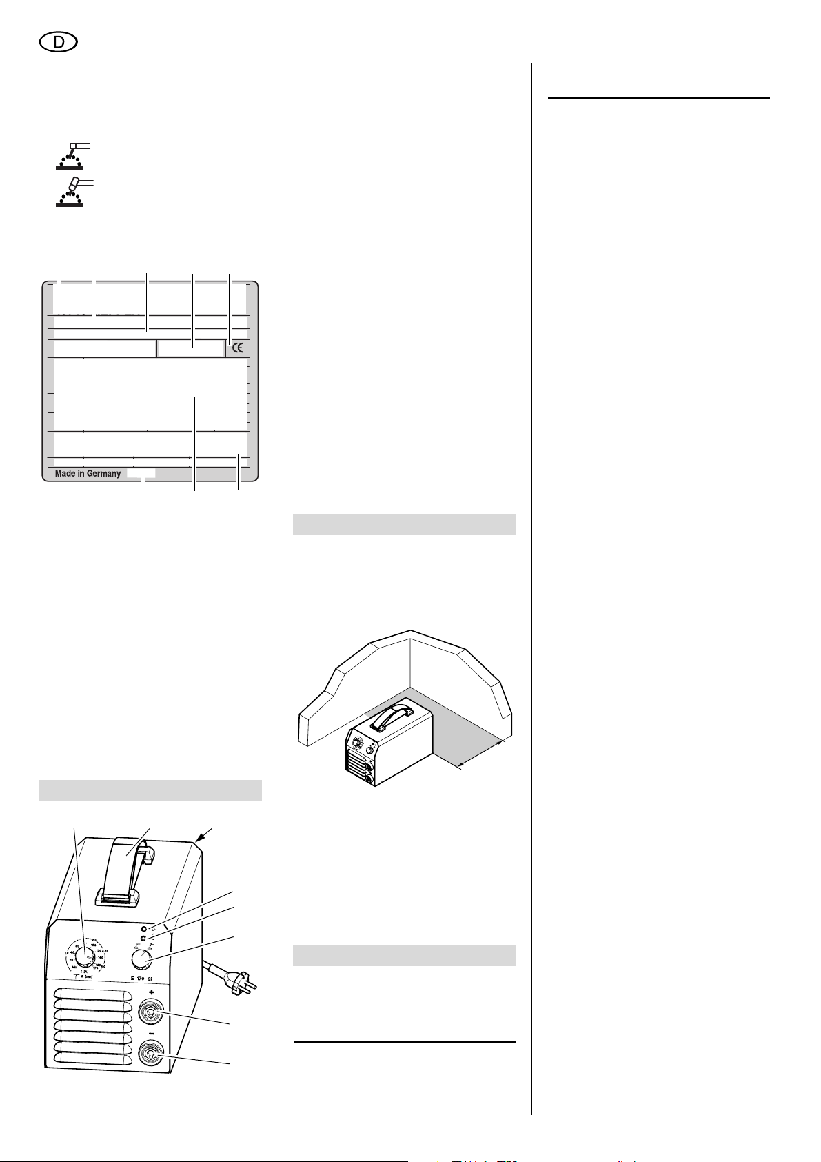
Angaben auf dem Leistungsschild:
1
2
1 Hersteller
2 Gerätebezeichnung
3 Seriennummer
4 Normenhinweis – Diese Gerät
erfüllt die Anforderungen der
genannten Norm
5 CE-Zeichen – Dieses Gerät
erfüllt die EU-Richtlinien gemäß
Konformitätserklärung
6 Entsorgungssymbol – Gerät
kann über Hersteller entsorgt
werden
7 Elektrische Leistungsdaten
8 Baujahr
345
78
6
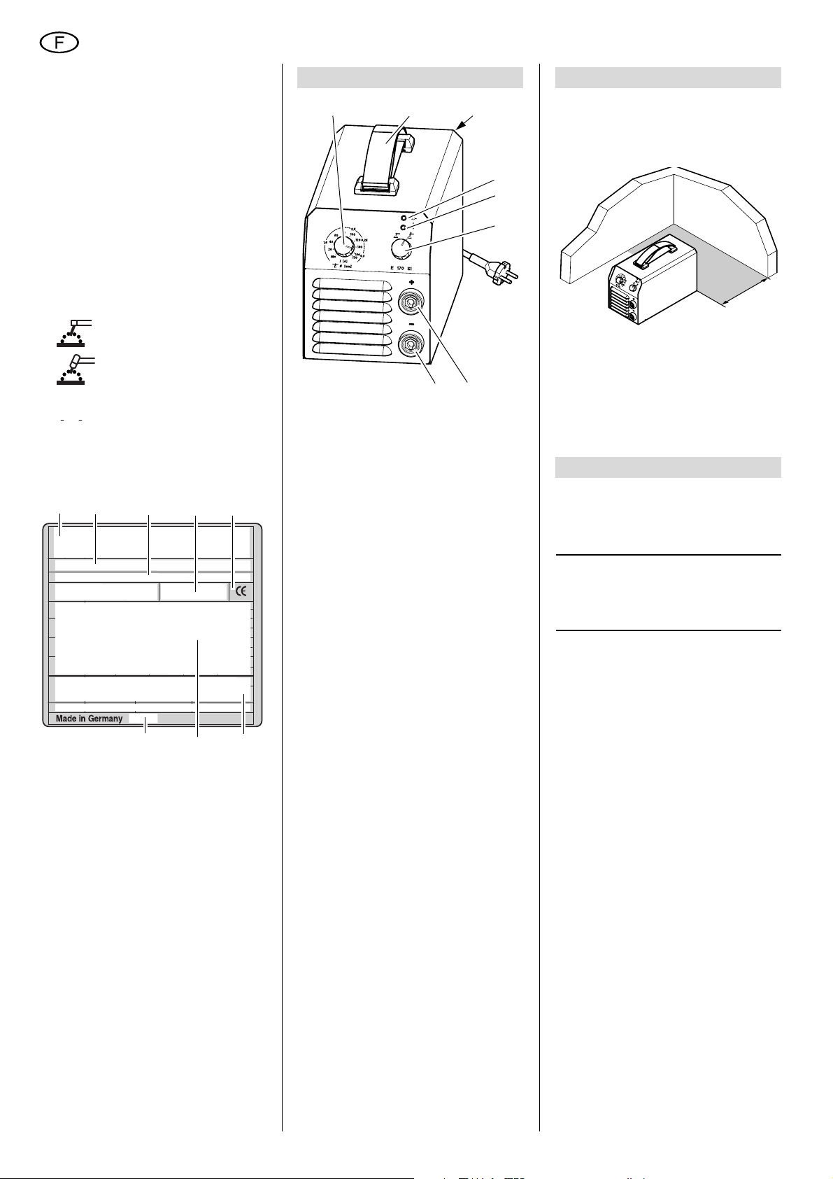
3. Bedienelemente
9
9 Schweißstromeinstellung
10
11
12
13
14
15
16
10 E 130, E 150, E 170 Si:
Trage-/Schultergurt
In der Länge verstellbar zum
Transport
− an der Hand (wie in der
Abb. dargestellt)
− über die Schulter.
E 140 SP/Plus: Tragegriff
11 Hauptschalter
schaltet das Gerät ein oder aus
12 Betriebsanzeige
13 Störungsanzeige
LED blinkt:
− bei Unterspannung
− bei Überspannung
− bei zu hoher Betriebs-
temperatur.
14 Umschalter Elektrode –
WIG DC (Lift-Arc-Zündung)
(Gilt nicht für E 140 SP/Plus)
15 Anschluss Schweißstrom + Pol
16 Anschluss Schweißstrom - Pol.
LED = Licht-Emittierende Diode,
dient als Kontrolleuchte.
4. Betriebsvorbereitung
4.1 Aufstellen
Achtung!
A
Stellen Sie das Gerät immer
nur auf den Gerätefüßen ab.
>20 cm
Das Gerät saugt an der Frontseite
und am Boden Luft an und gibt sie an
der Rückseite durch die Lüftungs
schlitze wieder ab. Achten Sie unbedingt auf einen ungehinderten Luftstrom. Der Abstand des Geräts von
Wänden oder anderen Geräten muss
mindestens 20 cm betragen.
-
5. Bedienung
Achtung!
A
Überprüfen Sie vor dem Einschalten des Gerätes sämtliche
Anschlüsse und Zuleitungen.
Hinweis:
3
Das Gerät verwendet beim Elek-
trodenschweißen die Hot-Start-, ArcForce- und Anti-Stick-Funktion.
Hot-Start-Funktion
Bei Berührung des Werkstücks mit der
Elektrode wird der eingestellte Schweiß
strom für kurze Zeit erhöht, um ein
sicheres Zünden des Lichtbogens zu
erreichen.
Die kurzfristige Erhöhung des Schweißstroms ist auf den maximalen Elektrodenstrom begrenzt.
Arc-Force-Funktion
Während des Schweißprozesses hält
das Gerät die Energie (Wärme) kons
tant, die in das Material eingebracht
wird, auch wenn sich der Abstand der
Elektrode zum Schweißbad ändert.
Anti-Stick-Funktion
Erkennt das Gerät einen Kurzschluss im
Schweißprozess, wird nach 0,5 Sekun
den auf Minimalstrom geschaltet, um ein
Ausglühen der Elektrode zu verhindern
-
-
5.1 Elektrodenschweißen
1. Schweißstromrückleitung am
- Pol anschließen.
2. Schweißleitung am + Pol anschlie-
ßen.
Achtung!
A
Beachten Sie die Verpackungshinweise zur Polung der Elektroden,
die Sie verwenden und polen Sie
gegebenenfalls die Anschlüsse um.
Achtung!
A
Die Lift-Arc-Zündung muss
beim Elektrodenschweißen ausgeschaltet sein (Gilt nicht für E 140 SP/
Plus). Zur Kontrolle den Drehschalter
gegen den Uhrzeigersinn drehen.
3. Schweißstromrückleitung an geeig-
neter Stelle am Werkstück befestigen.
4. Hauptschalter einschalten.
5. Gewünschten Schweißstrom ein-
stellen.
Das Schweißgerät ist jetzt betriebsbereit.
5.2 WIG-Schweißen
Bei Verwendung eines WIG-Schweißbrenners (optionales Zubehör) können
die Geräte auch für das WIG-Schweißen
eingesetzt werden.
1. Schweißstromkabel des WIG-
Schweißbrenners anschließen
(- Pol).
2. Gasversorgung des WIG-Brenners
prüfen.
3. Schweißstromrückleitung an geeig-
neter Stelle am Werkstück befestigen (+ Pol).
4. Hauptschalter einschalten.
-
4
Page 5
DEUTSCH
5. Gewünschten Schweißstrom einstellen.
6. Lift-Arc-Zündung einschalten
(Gilt nicht für E 140 SP/Plus).
Zur Kontrolle den Drehschalter im
Uhrzeigersinn drehen.
Das Schweißgerät ist jetzt betriebsbereit.
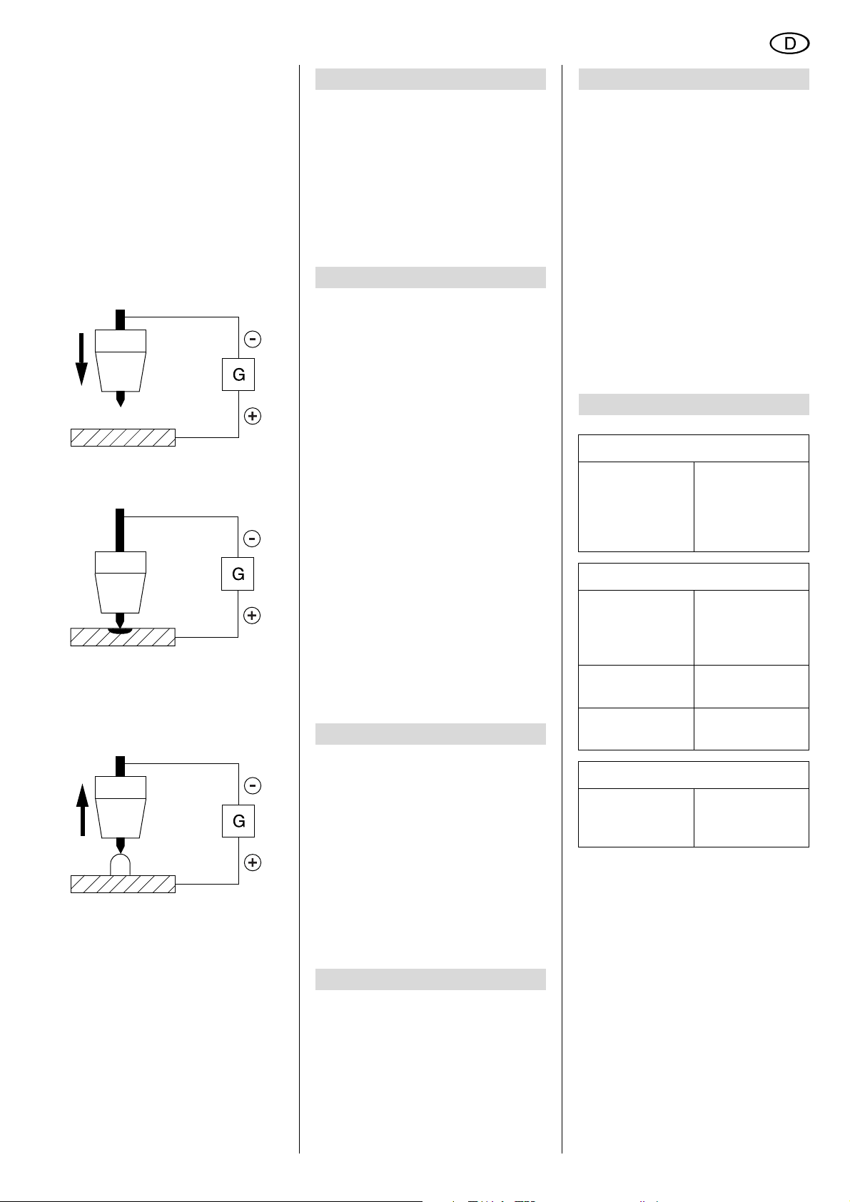
WIG-Schweißen
Die Zündung des Lichtbogens erfolgt
ausschließlich durch Berühren des
Werkstücks mit der Elektrode (Lift-ArcZündung).
Die Elektrode wird an das Werkstück
angenähert.
Durch den Kontakt der Elektrode mit
dem Werkstück entsteht ein Kurzschluss. Der Schweißstrom wird reduziert. Das Material wird erwärmt und ein
Kurzschlusslichtbogen erzeugt.
Durch Abziehen der Elektrode zündet
der Lichtbogen und es fließt der einge
stellte Schweißstrom (Gilt nicht für
E 140 SP/Plus).
-
5.3 Betrieb beenden
1. Hauptschalter auf „0“ stellen.
2. Verbindung der Schweißstromrückleitung zum Werkstück trennen.
3. Netzstecker ziehen.
6. Wartung
Das Schweißgerät ist weitgehend wartungsfrei.
Je nach Staubbelastung sollte es alle 4
bis 6 Monate mit trockener und ölfreier
Druckluft ausgeblasen werden.
Überprüfen Sie in regelmäßigen Abständen das Gerät auf sichtbare Mängel.
Benachrichtigen Sie bei Schäden an den
Kabeln eine Elektrofachkraft.
7. Lieferbares Zubehör
Für besondere Aufgaben erhalten Sie im
Fachhandel folgendes Zubehör – die
Abbildungen finden Sie auf der hinteren
Umschlagseite.
Dieses Zubehör ist mit dem Gerät getestet worden und garantiert ein problemloses Arbeiten.
A WIG-Schweißbrenner
SR 17 V für E 130/E 150,
E 140 SP/Plus
wird benötigt für WIG-Schweißen.
1) mit 2 m Anschlusslänge
2) mit 4 m Anschlusslänge
3) mit 8 m Anschlusslänge
B WIG-Schweißbrenner
SR 26 V für E 170 Si,
wird benötigt für WIG-Schweißen.
1) mit 4 m Anschlusslänge
2) mit 8 m Anschlusslänge
C Druckminderer mit 2 Manometern
1) ohne Absperrventil
2) mit Absperrventil
D Schweißschild
1) als Kopfhaube
2) Automatik-Schutzschirm
8. Reparatur
Gefahr!
A
Reparaturen an Elektrowerkzeugen dürfen nur durch eine Elektrofachkraft ausgeführt werden!
Reparaturbedürftige Schweißgeräte
können an die Service-Niederlassung
Ihres Landes eingesandt werden. Die
Adresse finden Sie bei der Ersatzteil
liste.
Bitte beschreiben Sie bei der Einsendung zur Reparatur den festgestellten
Fehler.
-
9. Umweltschutz
Das Verpackungsmaterial der Maschine
ist zu 100 % recyclingfähig.
Ausgediente Elektrowerkzeuge und
Zubehör enthalten große Mengen wert
voller Roh- und Kunststoffe, die ebenfalls einem Recyclingprozess zugeführt
werden können.
Die Anleitung wurde auf chlorfrei
gebleichtem Papier gedruckt.
-
10. Störungen
Das Schweißgerät ist mit einer Überlastsicherung ausgestattet. Bei zu hoher
Betriebstemperatur, Unter- oder Überspannung schaltet sich das Gerät automatisch ab.
− Die Anzeige „Störung“ blinkt.
Bei zu hoher Betriebstemperatur:
− Lassen Sie das Gerät eingeschaltet.
So kann der Lüfter das Gerät
schneller abkühlen.
− Die Anzeige „Störung“ erlischt,
wenn die Temperatur auf normale
Werte abgesunken ist.
Sie können jetzt weiterarbeiten.
Bei Unter- oder Überspannung:
− Prüfen Sie die Netzspannung.
11. Störungsbehebung
Spröde oder poröse Schweißnaht
Unsauberes
Werkstück?
Kein Schweißstrom
Schweißstromrückleitung gibt
keinen richtigen
Kontakt?
Anzeige "Störung" blinkt
Elektronik
defekt?
Keine Funktion des Gerätes
Netzsicherung
ausgelöst?
Rost, Fett oder
andere Verunreinigungen vor
dem Schweißen
entfernen.
Schweißstromrückleitung auf
richtigen Kon
takt prüfen.
Netzspannung
und Lüfter prüfen
Service
informieren
Netzsicherung
einschalten oder
wechseln.
-
5
Page 6

DEUTSCH
12. Technische Daten
Gerät E 130* E 140 SP* E 140 SP Plus* E 150* E 170 Si
Netzanschluss: 230 V (-15% / -20%) / 50 – 60 Hz
Leerlaufspannung Elektrode: V 90 103 85 90 90
Leerlaufspannung WIG: V 25 – 85 25 25
Arbeitsspannung Elektrode: V 20,4 – 25,2 20,4 – 25,6 20,4 – 26 20,4 – 26 20,4 – 26,8
Arbeitsspannung WIG: V 10,4 – 15,2 – 10,4 – 15,6 10,4 – 16 10,4 – 16,8
Stromeinstellbereich, stufenlos: A 10 – 130 10 – 140 10 – 140 10 – 150 10 – 170
Eingangsleistung max.: kVA 6,0 6,6 6,6 7,1 5,7
Eingangshöchststrom: A 26 29 29 31 25
Max. Einschaltdauer E 40 °C: % 25 15 20 25 25
Max. Einschaltdauer WIG 40 °C: % 35 – 25 35 35
60% Einschaltdauer E 40 °C: A 100 85 85 110 130
60% Einschaltdauer WIG 40 °C: A 115 – 100 130 140
100% Einschaltdauer E 40 °C: A 80 75 75 90 100
100% Einschaltdauer WIG 40 °C: A 100 – 85 110 110
Schutzart: IP23C IP23C IP23C IP23C IP23C
Verschweißbare Elektroden: Ø mm 3,25 3,25 3,25 3,25 (4,0 CrNi) 4,0
Kühlart: F F F F F
Netzsicherung: T16A T16A T16A T16A T16A
Maße L x B x H (mm): mm 300x130x210 300x130x210 300x130x210 300x130x210 400x210x240
Gewicht (netto): kg 6,2 5,8 6,0 6,3 7,8
* Achtung: Dieses Gerät erfüllt nicht die Anforderungen der EN/IEC 61000 3 -12. Wenn das Gerät an ein öffentliches Versorgungsnetzt angeschlossen werden soll, liegt es, ggf. nach Konsultation mit dem Betreiber des Versorgungsnetzes, in der Verantwortung
des Betreibers oder des Anwenders des Gerätes sicherzustellen, dass das Gerät angeschlossen werden kann.
6
Page 7
XS0015E3.fm Original operating instructions DEUTSCH
ENGLISH
Table of Contents
1. Please Read First!....................... 7
2. Safety Information ......................7
2.1 Specified conditions of use ...........7
2.2 General safety information............7
2.3 Symbols on the machine ..............7
3. Operating Elements....................8
4. Preparing for Operation ............. 8
4.1 Placing the machine .....................8
5. Operation.....................................8
5.1 Manual arc welding.......................8
5.2 TIG welding...................................8
5.3 Shutting down...............................9
6. Maintenance................................9
7. Available Accessories...........9/39
8. Repairs.........................................9
9. Environmental Protection..........9
10. Disorders.....................................9
11. Trouble Shooting........................9
12. Technical Specifications..........10
1. Please Read First!
These instructions are written in a way
that will enable you to safely use the
machine in a minimum of time. Here is
how to read the instructions:
− Read these instructions completely
before use. Pay special attention to
the safety information.
− These instructions are intended for
skilled arc weldors or other specialists of similar qualification.
− Keep all documents supplied with
the machine for future reference.
Retain proof of purchase for possi
ble warranty claims.
− If you hire out or sell this machine be
sure to hand over all documents
supplied with the machine.
− The equipment manufacturer is not
liable for any damage arising from
disregard of these instructions.
The information in these instructions is
marked as under:
Danger!
Warning of personal
injury or environmental
damage.
Risk of electric shock!
Risk of personal injury
by electric shock.
Caution!
Risk of material damage
-
Note:
Supplementary information.
− Numbers in illustrations (1, 2, 3, ...)
− indicate component parts;
− are consecutively numbered;
− refer to the corresponding num-
bers in brackets (1), (2), (3) ... in
the neighbouring text.
− Instructions to be carried out in
sequence are numbered.
− Instructions which can be carried
out in any sequence are preceded
by a bullet (•).
− Listing are preceded by a M-dash (–).
2. Safety Information
2.1 Specified conditions of
use
This welding machine is intended for
welding all metals.
The welding machine and the accessory
kit supplied conform to the relevant regulations applicable at the time of delivery.
This welding machine is intended for
operation by professional arc weldors or
specialists of similar qualification.
Permissible welding processes:
− Manual arc welding
− TIG DC (with optional accessories)
for all metals, except aluminium.
For machine performance see “Technical Specifications”.
Any other use is not as specified and
prohibited.
Unspecified use, modification of the
machine or use of parts not tested and
approved by the equipment manufac
turer could cause unforeseeable damage!
-
2.2 General safety information
• When using this machine, observe
the following safety instructions to
exclude the risk of personal injury or
material damage.
• Follow the specific safety instructions in the respective chapters.
• Follow the legal directives or regulations for the prevention of accidents
pertaining to the handling of arc
welding machines.
Danger!
B
Electric potential!
• Connect the machine only to a properly earthed outlet.
If in doubt check with a qualified
electrician!
• Service and repairs to the machine
must only be made by qualified elec
tricians.
• Unplug before removing the
machine's cover.
A
Danger!
• Wear sufficient protective clothing
when welding.
• Always use a welding visor and
welder's gloves.
They provide protection against flying sparks and arc radiation.
• All metal fumes are detrimental to
health!
When working indoors ensure sufficient ventilation and extraction in
order to not exceed the max. permissible workplace pollutant concentration.
The fumes of lead, cadmium, copper, chromium, nickel, zinc and
beryllium are particularly harmful!
Caution!
A
• Never weld earthed metal.
Welding earthed metal may cause
damage to the protective earth conductors by stray currents.
• Never use the welding machine for
thawing pipes.
• Always attach the earth cable
directly to the weld metal and as
close as possible to the welding
spot.
• Always carry the welding machine at
the carrying strap when transporting it.
• Special care is required when working near computers, electronically
controlled equipment or in the proximity of magnetic data media (sound
recording tapes, floppy disks, data
recording tapes, credit cards, etc.).
The arc start can cause misfunction
of this type of equipment or data
loss.
2.3 Symbols on the machine
Arc welding with coated
stick electrodes
Tungsten Inert-gas Welding
(TIG welding)
(not applicable for
E 140 SP/Plus)
-
7
Page 8
ENGLISH
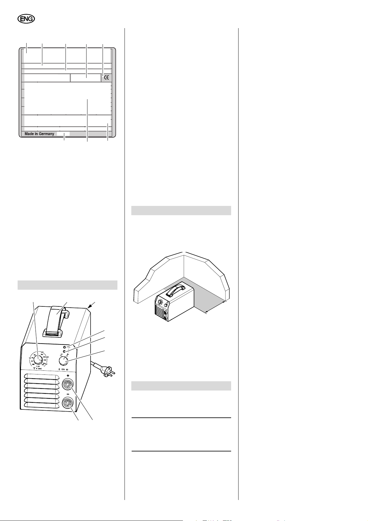
Information on the name plate:
1
2
1 Manufacturer
2 Machine designation
3 Serial number
4 Standard information – This
machine meets the requirements
of the standards mentioned
5 CE mark – This machine con-
forms to EC directives as per
declaration of conformity
6 Waste disposal symbol – the
machine can be disposed of
through the manufacturer
7 Electrical performance data
8 Date of manufacture
345
8
7
3. Operating Elements
9
10
11
11 Master switch
switches the unit ON or OFF
12 Equipment-on indicator light
13 Fault indicator light
The LED flashes:
− in case of a low-voltage
condition
− in case of an over-voltage
condition
− in case of excessive an
operating temperature.
14 Selector switch
Manual Arc MMA – TIG DC
6
(lift-arc ignition)
(not applicable for E 140 SP/Plus)
15 Welding current socket (+ pole)
16 Welding current socket (– pole)
LED = Light-Emitting Diode, used as
indicator light.
4. Preparing for Operation
4.1 Placing the machine
Caution!
A
Always stand the machine on
its feet only.
This brief increase of the welding current
is limited to the maximum electrode cur
rent.
Arc-force function
During the welding process the machine
keeps the energy (heat) brought into the
weld metal at a constant level, even if
the distance between electrode and
weld pool varies.
Anti-stick function
If the machine detects a short-circuit in
the welding process, it will switch to minimum current within 0.5 sec to keep the
electrode from burning out.
5.1 Manual arc welding
1. Connect the earth cable to the –
pole.
2. Connect the welding cable to the +
pole.
Caution!
A
Note information on polarity
shown on the packaging of the electrodes used; reverse polarity, if necessary.
Caution!
A
For manual arc welding the
Lift-arc ignition must be disabled (not
applicable for E 140 SP/Plus). To
check, turn the rotary switch counterclockwise.
3. Attach earth cable at a suitable loca-
tion of the workpiece.
4. Turn master switch ON.
5. Set desired welding current.
The welding machine is now operational.
-
15
16
9 Welding current regulator
10 E 130, E 150, E 170 Si
Carrying strap/shoulder strap
Adjustable in length for carrying
− by hand (shown in illustration)
− on the shoulder.
E 140 SP/Plus : carrying handle
12
13
14
>20 cm
The machine draws in air at its front
and bottom, which is given off
through the ventilating slots at the
rear. Ensure an unhindered airflow.
The distance of the machine to walls
or other equipment must be at least
cm.
20
5. Operation
Caution!
A
Check all connections and
supply lines before turning on.
Note:
3
For manual arc welding this
machine uses the Hot-start, Arc-force
and Anti-stick functions.
Hot-start function
When contacting the weld metal with the
electrode, the set welding current is
increased for a short period to ensure
that the arc will start.
5.2 TIG welding
When using a TIG welding torch
(optional accessory), both models can
also be used for TIG welding.
1. Connect the welding current cable
of the TIG torch
(– pole).
2. Check the gas supply to the TIG
torch.
3. Attach the earth cable at a suitable
location of the workpiece (+
4. Turn master switch ON.
5. Set desired welding current.
6. Activate Lift-arc ignition.
(not applicable for E 140 SP/Plus)
To check, turn the rotary switch
clockwise.
The welding machine is now operational.
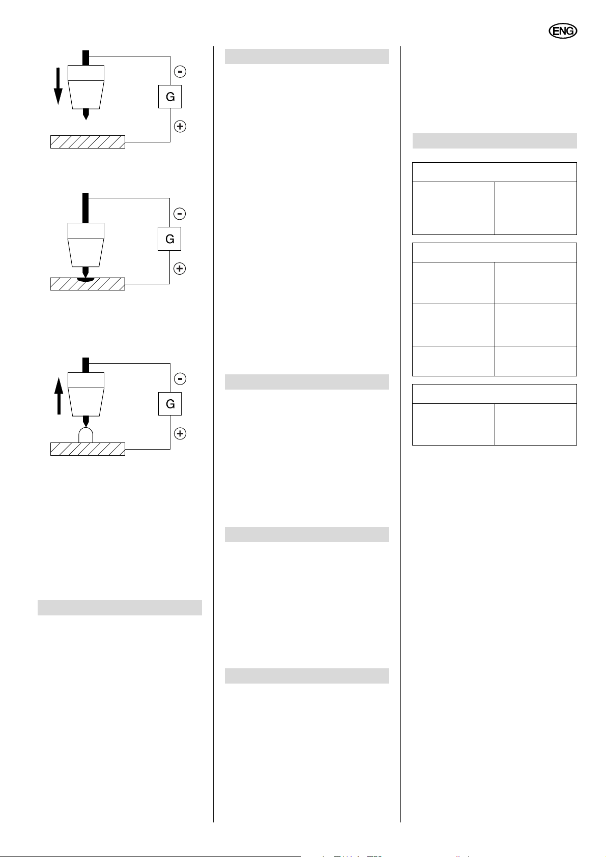
TIG welding
The arc can only be started by touching
the workpiece with the electrode (Lift-arc
ignition).
pole).
8
Page 9
ENGLISH
Approach the weld metal with the electrode.
Contact of the electrode to the weld
metal causes a short-circuit, the welding
current is reduced. The material is
heated up and a short arc generated.
By lifting the electrode the arc is started
and will burn at the set welding current
(not applicable for E 140 SP/Plus).
7. Available Accessories
For special welding tasks the following
accessories are available at specialised
dealers – see back cover for illustrations.
These accessories have been tested
with the machine and ensure operation
without any problem.
A TIG welding torch
SR 17 V for E 130/E 150,
E 140 SP/Plus
required for TIG welding.
1) 2 m torch leads
2) 4 m torch leads
3) 8 m torch leads
B TIG welding torch
SR 26 V for E 170Si ,
required for TIG welding.
1) 4 m torch leads
2) 8 m torch leads
C Pressure regulator with 2 pressure
gauges
1) without stop valve
2) with stop valve
D Welding visor
1) helmet
2) automatic screen
8. Repairs
Danger!
A
Repairs to power tools must be
carried out by qualified electricians
only!
Welding machines in need of repair can
be sent to the service centre of your
country. Refer to the spare parts list for
the address.
Please attach a description of the fault to
the power tool.
− The “Fault” indicator light will go out
when the temperature has fallen off
to normal levels.
You can now continue welding.
In case of under- or overvoltage:
− Check the mains voltage.
11. Trouble Shooting
Brittle or porous weld seam
Workpiece not
clean?
No welding current
Earth cable making poor contact?
The “Fault” indicator light is
flashing.
Electronics
faulty?
No function of machine
Supply circuit
fuse blown or
cut-out?
Remove rust,
grease or other
contamination
prior to welding.
Check earth
cable for proper
contact.
Check mains
voltage and fan
Contact
service centre.
Replace or turn
ON again.
5.3 Shutting down
1. Set master switch to “0”.
2. Disconnect the earth cable from the
workpiece.
3. Unplug the power cable.
6. Maintenance
This welding machine contains no userserviceable parts.
Depending on dust accumulation the
dust should be blown out from the
machine with dry and oil-free com
pressed air every 4 - 6 months.
Periodically perform a check for visible
damage.
Contact a qualified electrician if any of
the cables are damaged.
-
9. Environmental Protection
The machine's packaging can be 100 %
recycled.
Worn out power tools and accessories
contain considerable amounts of valuable raw and rubber materials, which can
be recycled.
These instructions are printed on paper
produced with elemental chlorine free
bleaching process.
10. Disorders
The welding machine is equipped with
an overload protection. It will automati
cally turn OFF in case of excessive operating temperatures and under- or overvoltage.
− The “Fault” indicator light is flashing.
In case of an excessive operating temperature:
− DO NOT turn the machine OFF,
in order for the fan to cool the
machine down faster.
-
9
Page 10

ENGLISH
12. Technical Specifications
Model E 130* E 140 SP* E 140 SP Plus* E 150* E 170 Si
Supply voltage 230 V (-15% / -20%) / 50 – 60 Hz
Open-circuit voltage manual arc V 90 103 85 90 90
Open-circuit voltage TIG V 25 – 85 25 25
Working voltage manual arc V 20.4 – 25.2 20.4 – 25.6 20.4 – 26 20.4 – 26 20.4 – 26.8
Working voltage TIG V 10.4 – 15.2 – 10.4 – 15.6 10.4 – 16 10.4 – 16.8
Current setting range, stepless A 10 – 130 10 – 140 10 – 140 10 – 150 10 – 170
Power input max. kVA 6.0 6.6 6.6 7.1 5.7
Max. input current A 26 29 29 31 25
Max. duty cycle E 40 °C % 25 15 20 25 25
Max. duty cycle TIG 40 °C % 35 – 25 35 35
60% duty cycle E 40 °C: A 100 85 85 110 130
60% duty cycle TIG 40 °C A 115 – 100 130 140
100% duty cycle E 40 °C A 80 75 75 90 100
100% duty cycle TIG 40 °C A 100 – 85 110 110
Protection class IP23C IP23C IP23C IP23C IP23C
Max. electrode size Ø mm 3.25 3.25 3.25 3.25 (4.0 CrNi) 4.0
Cooling F F F F F
Supply circuit fuse T16A T16A T16A T16A T16A
Dimensions L x W x H (mm) mm 300x130x210 300x130x210 300x130x210 300x130x210 400x210x240
Weight (net) kg 6.2 5.8 6.0 6.3 7.8
* Warning: This device does not meet the requirements of EN/IEC 61000-3-12. Prior to connecting the device to a mains supply, the
owner or user of the device must ensure that the device can be connected, if necessary after consultation with the operator of the
mains supply network.
10
Page 11
XS0015F3.fm Instructions d’utilisation origi- nales
FRANÇAIS
Table des matières
1. À lire impérativement !.............11
2. Consignes de sécurité .............11
2.1 Utilisation conforme aux
prescriptions ...............................11
2.2 Consignes générales de
sécurité .......................................11
2.3 Symboles figurant sur l'appareil..12
3. Éléments de commande...........12
4. Mise en ordre de marche .........12
4.1 Mise en place..............................12
5. Manipulation..............................12
5.1 Soudage à électrodes.................13
5.2 Soudage TIG ..............................13
5.3 Mise hors service........................13
6. Maintenance..............................13
7. Accessoires disponibles..... 13/39
8. Réparations...............................13
9. Protection de l'environnement..13
10. Dérangements...........................13
11. Élimination des défauts ...........14
12. Caractéristiques techniques.... 14
1. À lire impérativement !
Ces instructions d'utilisation ont été
conçues de manière à vous permettre
de travailler avec l'appareil rapidement
et de manière sûre. Les remarques qui
suivent vous aideront à utiliser ces ins
tructions :
− Avant la mise en service, lire soigneusement les instructions d'utilisation dans leur intégralité. Observer en particulier les consignes de
sécurité.
− Ces instructions s'adressent à des
soudeurs à l'arc qualifiés ou du per
sonnel de qualification équivalente.
− Conserver tous les documents fournis avec l'appareil afin de pouvoir en
prendre connaissance en cas de
besoin. Conserver le justificatif
d'achat au cas où vous auriez
besoin de faire valoir la garantie.
− Lorsque vous prêtez ou vendez
l'appareil, remettre au nouvel utilisateur l'ensemble de la documentation
fournie.
− Le constructeur décline toute responsabilité en cas de dommages
liés au non-respect de ces instruc
tions d'utilisation.
Les informations qui figurent dans ces
instructions d'utilisation sont signalées
comme suit :
-
-
Danger !
Risque de dommages
corporels ou d'atteinte à
l'environnement.
Risque d'électrocution !
Risque de dommages
corporels causés par
l'électricité.
Attention !
Risque de dégâts matériels.
Remarque :
Informations complémentaires.
− Les numéros des illustrations
(1, 2, 3, ...)
− désignent des pièces données ;
− sont attribués dans l'ordre ;
− se réfèrent aux chiffres entre
parenthèses (1), (2), (3) ... dans
le texte adjacent.
− Lorsqu'une manipulation doit être
effectuée dans un ordre précis, les
instructions sont numérotées.
− Les consignes pouvant être effectuées dans n'importe quel ordre sont
identifiées par un point.
− Les énumérations sont signalées
par un tiret.
2. Consignes de sécurité
2.1 Utilisation conforme aux
prescriptions
L'appareil de soudage est conçu pour
souder tous les métaux.
L'appareil et l'équipement pour poste de
soudage sont conformes aux directives
légales en vigueur à la livraison.
Cet appareil est prévu pour être utilisé
par des soudeurs à l'arc qualifiés ou du
personnel de qualification équivalente.
Procédés de soudage autorisés :
− Soudage à électrodes
− Soudage TIG CC (avec accessoi-
res en option) pour tous les métaux
sauf l'aluminium.
Performances de l'appareil : voir "Caractéristiques techniques".
Toute autre utilisation de cet appareil
est contraire aux prescriptions et
interdite.
Des dommages imprévisibles
peuvent survenir en cas d'utilisation non
conforme, de changements apportés à
l'appareil ou d'utilisation de pièces qui ne
sont pas contrôlées et autorisées par le
constructeur !
2.2 Consignes générales de
sécurité
• Lorsque vous utilisez l'appareil, respecter les consignes de sécurité qui
suivent pour prévenir tout risque de
blessures ou de dommages matériels.
• Tenir compte des consignes de
sécurité particulières figurant dans
chaque chapitre.
• Tenir compte des directives légales
et règles de prévention des accidents relatives au maniement
d'appareils de soudage à l'arc.
Danger !
B
Tension électrique.
• Ne raccorder l'appareil qu'à une
source de courant dont les dispositifs de sécurité fonctionnent parfaitement.
S'adresser à un électricien en cas
de doute !
• Toute réparation ou modification de
l'appareil doit être effectuée par un
électricien qualifié.
• Débrancher l'appareil du secteur
avant de l'ouvrir.
A
Danger !
• Porter impérativement des vêtements protecteurs adaptés aux travaux de soudage.
• Utiliser obligatoirement un bouclier
et des gants.
Ils protègent des projections d'étincelles et du rayonnement de l'arc
électrique.
• Toutes les vapeurs métalliques sont
toxiques !
Veiller à un renouvellement d'air suffisant et constant pendant les travaux de soudure en intérieur afin
que les concentrations maximales
tolérées de produits toxiques ne
soient pas dépassées sur le lieu de
travail.
Les vapeurs de plomb, de cadmium,
de cuivre, de chrome, de nickel, de
zinc et de béryllium sont particuliè
rement dangereuses !
A
• Ne jamais souder une pièce reliée à
la terre.
Une dégradation éventuelle du
conducteur de protection par des
courants de fuite est ainsi évitée
(couplage).
• Ne jamais utiliser l'appareil de soudage pour dégeler des tuyaux.
• Toujours fixer l'étrier du circuit retour
du courant de soudage directement
au niveau de la pièce et le plus près
possible de la soudure.
Attention !
-
11
Page 12
FRANÇAIS
• Toujours porter l'appareil par la sangle de transport.
• Faire très attention lorsque les travaux de soudage s'effectuent à
proximité d'ordinateurs, d'appareils
à commande électronique ou de
supports de données magnétiques
(bandes de magnétophones, dis
quettes, bandes magnétiques, cartes bancaires, etc.).
Des anomalies ou des pertes de
données peuvent se produire pendant l'amorçage à l'arc.
-
2.3 Symboles figurant sur
l'appareil
Soudage à l'arc avec
baguette enveloppée
Soudage tungstène gaz
inerte (soudage TIG)
(ne s’applique pas à
E 140 SP/Plus)
Indications figurant sur la plaque
signalétique :
1
2
1 Constructeur
2 Nom de l'appareil
3 Numéro de série
4 Norme de référence – cet appa-
reil est conforme aux exigences
de la norme indiquée.
5 Sigle CE – cet appareil est
conforme aux directives européennes comme indiqué dans la
déclaration de conformité.
6 Symbole de mise au rebut –
l'appareil peut être remis au fabricant.
7 Caractéristiques électriques
8 Année de construction
345
8
7
6
3. Éléments de commande
9
9 Réglage du courant de soudage
10 Sangle/bandoulière
Sangle de longueur réglable
pour le transport
− à la main (voir illustration)
− sur l'épaule
E 140 SP/Plus : poignée
11 Interrupteur principal
permet d'allumer et d'éteindre
l'appareil
12 Affichage de fonctionnement
13 Affichage des défauts
DEL clignotante :
− en cas de sous-tension
− en cas de surtension
− en cas de surchauffe
14 Commutateur électrode –
TIG DC (amorçage de l'arc)
(ne s’applique pas à E 140 SP/
Plus)
15 Connecteur pour courant de
soudage pôle +
16 Connecteur pour courant de
soudage pôle
DEL = Diode ElectroLuminescente,
sert de voyant de contrôle.
10
-
16
11
15
12
13
14
4. Mise en ordre de marche
4.1 Mise en place
Attention !
A
Toujours placer l'appareil sur
ses pieds.
>20 cm
L'appareil aspire l'air par la façade et
la face inférieure et le rejette par les
grilles d'aération à l'arrière. Veiller
impérativement à ce que la circula
tion de l'air ne soit pas gênée. L'appareil doit être situé à 20 cm au moins
des cloisons ou d'autres machines.
-
5. Manipulation
Attention !
A
Vérifier tous les raccordements et les connexions avant la
mise en marche de l'appareil.
Remarque :
3
Lors du soudage à électrodes,
l'appareil utilise les fonctions Hot-Start,
Arc-Force et Anti-Stick.
Fonction Hot-Start
Lors du contact de la pièce à souder
avec l'électrode, le courant de soudage
paramétré est intensifié pendant un
court instant afin d'amorcer l'arc en toute
sécurité.
L'augmentation momentanée du courant
de soudage est limitée au courant
d'électrode maximal.
Fonction Arc-Force
L'appareil maintient constante l'énergie
(chaleur) apportée au matériau pendant
le soudage, y compris lorsque la dis
tance des électrodes au bain de soudure
varie.
Fonction Anti-Stick
Si l'appareil détecte un court-circuit en
cours de soudage, il passe au courant
minimal au bout de 0,5 s pour éviter que
l'électrode ne se consume.
-
12
Page 13

FRANÇAIS
5.1 Soudage à électrodes
1. Raccorder le circuit retour du cou-
rant de soudage au pôle -.
2. Raccorder le câble de soudage au
nées sur l'emballage pour la polarisation des électrodes utilisées et inverser les connexions si besoin est.
désactivé en mode de soudage à
électrodes (ne s’applique pas à
E 140 SP/Plus). Tourner le commutateur rotatif dans le sens contraire des
aiguilles d'une montre.
3. Fixer le circuit retour du courant de
4. Enclencher l'interrupteur principal.
5. Régler le courant de soudage dési-
+.
pôle
Attention !
A
Respecter les indications don-
Attention !
A
L'amorçage de l'arc doit être
soudage à un endroit adéquat sur la
pièce à souder.
ré.
L'appareil de soudage est maintenant prêt à l'emploi.
Le contact de l'électrode avec la pièce
provoque un court-circuit. Le courant de
soudage diminue. La matière chauffe et
un arc de court-circuit jaillit.
Le retrait de l'électrode amorce l'arc et le
courant de soudage programmé passe
(ne s’applique pas à E 140 SP/Plus).
B Chalumeau TIG
SR 26 V pour E 170 Si,
nécessaire pour le soudage TIG
1) avec câble de 4 m
2) avec câble de 8 m
C Détendeur à 2 manomètres
1) sans vanne d'arrêt
2) avec vanne d'arrêt
D Bouclier
1) sous forme de visière
2) écran protecteur automatique
8. Réparations
Danger !
A
Les outils électriques doivent
être réparés exclusivement par des
électriciens professionnels !
Les appareils à souder nécessitant une
réparation peuvent être envoyés au cen
tre de service après-vente de votre pays.
L'adresse figure avec la liste des pièces
de rechange.
Prière de joindre à l'outil expédié une
description du défaut constaté.
-
5.2 Soudage TIG
Les appareils peuvent aussi servir pour
effectuer des travaux selon le procédé
de soudage TIG en utilisant un chalu
meau de soudage TIG (en option).
1. Raccorder le câble du courant de
soudage du chalumeau TIG (pôle -).
2. Contrôler l'alimentation en gaz du
chalumeau TIG.
3. Fixer le circuit retour du courant de
soudage à un endroit adéquat sur la
pièce à souder (pôle +).
4. Enclencher l'interrupteur principal.
5. Régler le courant de soudage désiré.
6. Allumer l'amorçage de l'arc
(ne s’applique pas à E 140 SP/Plus).
Tourner le commutateur rotatif dans
le sens des aiguilles d'une montre à
titre de contrôle.
L'appareil de soudage est maintenant prêt à l'emploi.
Soudage TIG
L'amorçage de l'arc ne s'effectue que
par contact de la pièce avec l'électrode
(amorçage de l'arc).
L'électrode est approchée de la pièce à
souder.
-
5.3 Mise hors service
1. Positionner l'interrupteur principal
sur "0".
2. Séparer le circuit retour du courant
de soudage de la pièce soudée.
3. Débrancher la fiche d’alimentation.
6. Maintenance
L'appareil de soudage ne nécessite
aucune maintenance.
Selon la quantité de poussière, l'appareil
doit être nettoyé tous les 4 à 6 mois en
soufflant de l'air comprimé sec et sans
huile.
Effectuer régulièrement un contrôle
visuel de l'appareil.
Contacter un électricien en cas de dommages au niveau des câbles.
7. Accessoires disponibles
Vous trouverez dans les commerces
spécialisés les accessoires suivants
destinés aux travaux spécifiques – les
illustrations figurent sur la dernière page
de couverture.
Ces accessoires ont été testés avec
l'appareil et garantissent ainsi un travail
sans problèmes.
A Chalumeau TIG
SR 17 V pour E 130/E 150,
E 140 SP/Plus
nécessaire pour le soudage TIG
1) avec câble de 2 m
2) avec câble de 4 m
3) avec câble de 8 m
9. Protection de l'environnement
Le matériau d'emballage de la machine
est recyclable à 100 %.
Les outils et accessoires électriques qui
ne sont plus utilisés contiennent de
grandes quantités de matières premières et de matières plastiques de qualité
pouvant également être recyclées.
Les présentes instructions ont été imprimées sur papier blanchi sans chlore.
10. Dérangements
L'appareil de soudage est muni d'un dispositif de sûreté contre la surchauffe. En
cas de température de service trop élevée, de sous-tension ou de surtension,
l'appareil s'éteint automatiquement.
− L'affichage "Erreur" clignote.
En cas de surchauffe :
− Laisser l'appareil allumé.
Le ventilateur peut ainsi refroidir
l'appareil plus rapidement.
− Le témoin "Erreur" s'éteint lorsque la
température est revenue à des
valeurs habituelles.
Les travaux de soudure peuvent
reprendre.
En cas de sous-tension ou surtension :
− Vérifier la tension d'alimentation.
13
Page 14

FRANÇAIS
11. Élimination des défauts
Soudure cassante ou poreuse
Pièce à souder
sale ?
Éliminer les traces de rouille, de
graisse et autres
impuretés avant
de commencer à
souder.
Absence de courant de soudage
Mauvais contact
au niveau du circuit retour du
courant de soudage ?
L'affichage
"Erreur" clignote.
Contrôler le
contact du circuit retour du
courant de soudage.
Vérifier la tension d'alimentation et le ventilateur.
Absence de courant de soudage
Électronique
défectueuse ?
L'appareil ne fonctionne pas
Fusible de secteur déclenché ?
En informer
le service aprèsvente.
Réenclencher ou
remplacer le fusible de secteur.
12. Caractéristiques techniques
Appareil E 130* E140 SP* E 140 SP Plus* E 150* E 170 Si
Tension secteur : 230 V (-15% / -20%) / 50 – 60 Hz
Tension à vide – électrode : V 90 103 85 90 90
Tension à vide – TIG : V 25 – 85 25 25
Tension de service – électrode : V 20,4 – 25,2 20,4 – 25,6 20,4 – 26 20,4 – 26 20,4 – 26,8
Tension de service – TIG : V 10,4 – 15,2 – 10,4 – 15,6 10,4 – 16 10,4 – 16,8
Capacité en continu : A 10 – 130 10 – 140 10 – 140 10 – 150 10 – 170
Puissance d'entrée max. : kVA 6,0 6,6 6,6 7,1 5,7
Courant d'entrée max. : A 26 29 29 31 25
Facteur de marche max. E 40 °C : % 25 15 20 25 25
Facteur de marche max. TIG 40 °C : % 35 – 25 35 35
Facteur de marche 60% E 40 °C : A 100 85 85 110 130
Facteur de marche 60% TIG 40 °C : A 115 – 100 130 140
Régime permanent E 40 °C : A 80 75 75 90 100
Régime permanent TIG 40 °C : A 100 – 85 110 110
Indice de protection : IP23C IP23C IP23C IP23C IP23C
Baguettes à souder : Ø mm 3,25 3,25 3,25 3,25 (4,0 CrNi) 4,0
Mode de refroidissement : F F F F F
Fusible de secteur : T16A T16A T16A T16A T16A
Dimensions L x l x H (mm) : mm 300x130x210300x130x210 300x130x210 300x130x210 400x210x240
Poids (net) : kg 6,2 5,8 6,0 6,3 7,8
* Avis : Cet appareil ne satisfait pas aux exigences EN/IEC 61000 3 -12. S'il doit être branché sur un réseau de distribution public,
cela est, le cas échéant après avoir consulté l'exploitant du réseau de distribution, du ressort de l'exploitant ou de l'utilisateur de
l'appareil d'assurer que ce dernier peut être branché.
14
Page 15

XS0015H3.fm Origineel gebruikaanwijzing NEDERLANDS
NEDERLANDS
Inhoudstafel
1. Lees deze tekst voor u begint!15
2. Veiligheidsvoorschriften......... 15
2.1 Voorgeschreven gebruik van
het systeem ...............................15
2.2 Algemene
veiligheidsvoorschriften ............. 15
2.3 Symbolen op het apparaat ........ 16
3. Bedieningsfuncties .................16
4. Bedrijfsvoorbereiding .............16
4.1 Opstellen ...................................16
5. Bediening .................................16
5.1 Elektrodelassen .........................17
5.2 TIG-lassen .................................17
5.3 Het apparaat uitschakelen .........17
6. Onderhoud ...............................17
7. Beschikbare accessoires...17/39
8. Reparatie ..................................17
9. Milieubescherming ..................17
10. Storingen..................................17
11. Problemen oplossen ...............18
12. Technische gegevens .............18
1. Lees deze tekst voor u
begint!
Deze gebruiksaanwijzing werd zo vervaardigd, dat u snel en veilig met uw toestel kunt werken. Hier een kleine wegwijzer hoe u deze gebruiksaanwijzing dient
te lezen:
− Lees deze gebruiksaanwijzing vóór
de ingebruikneming geheel door.
Let hierbij vooral op de veiligheidsin
structies.
− Deze gebruiksaanwijzing richt zich
aan geschoolde lichtbooglassers of
aan vakkrachten met soortgelijke
kwalificatie.
− Bewaar alle met het apparaat geleverde documenten op, opdat u zich
bij behoefte kunt informeren.
Bewaar het koopbewijs voor eventu
ele garantiegevallen op.
− Indien u het apparaat eens uitleent
of verkoopt, geef dan alle meegele
verde apparaatdocumenten mee.
− Voor beschadigingen die door veronachtzaming van deze gebruiksaanwijzing ontstaan, overneemt de
fabrikant geen aansprakelijkheid.
De informaties in deze gebruiksaanwijzing zijn als volgt gekenmerkt:
Gevaar!
Waarschuwing voor
lichamelijk letsel of
milieuschade.
Gevaar voor elektrische
schok!
Waarschuwing voor
lichamelijke letsel door
elektrische schok.
Oppassen!
Waarschuwing voor
materiële schade.
Opmerking:
aanvullende informaties.
− Getallen in afbeeldingen (1, 2, 3, ...)
− kenmerken afzonderlijke delen;
− zijn doorlopend genummered;
− refereren naar de desbetref-
fende getallen in haakjes (1), (2),
(3) ... in de naburige tekst.
− Instructies, waarbij op de volgorde
moet worden gelet, zijn doorgenum
merd.
− Instructies met willekeurige volgorde
zijn met een punt gekenmerkt.
− Lijsten zijn met een streep gekenmerkt.
2. Veiligheidsvoorschriften
2.1 Voorgeschreven gebruik
van het systeem
Het lasapparaat is bedoeld voor het lassen van alle metalen.
Het lasapparaat en de bijbehorende lasplaatsuitrusting beantwoorden bij uitlevering aan de gebruikelijke bepalingen.
Het lasapparaat is bedoeld voor gebruik
door opgeleide booglasser of vakmen
sen met een gelijkaardige kwalificatie.
Toegelaten lasmethoden:
− Elektrodelassen
− TIG DC (met optionele accessoires)
voor alle metalen met uitzondering
van aluminium.
Toestelgegevens zie "Technische gegevens".
-
Elke andere toepassing geldt als
onreglementair en is verboden.
-
Door onreglementair gebruik, veranderingen aan het apparaat of door het
gebruik van onderdelen die niet door de
fabrikant werden gekeurd en vrijgegeven, kunnen niet te voorziene beschadigingen ontstaan!
2.2 Algemene veiligheids-
voorschriften
• Let bij de gebruik van dit apparaat
op de volgende veiligheidsinstruc
ties, om gevaren voor personen of
materiële schade te vermijden.
• Houd rekening met de bijzondere
veiligheidsinstructies in de desbe
treffende hoofdstukken.
• Houd rekening met de wettelijke
richtlijnen of ongevallenpreventie
voorschriften voor de omgang met
lichtboog-lasapparaten.
Gevaar!
B
Elektrische spanning
• Sluit het apparaat uitsluitend aan op
een stroombron, waarvan de beveili
gingsinrichtingen correct functioneren.
In geval van twijfel neemt u contact
op met een elektromonteur!
• Reparaties en ingrepen in de apparatuur mogen uitsluitend door elektromonteurs uitgevoerd worden.
• Koppel het apparaat van de netvoeding, alvorens het te openen.
-
-
-
A
Gevaar!
• Draag tijdens het lassen in elk geval
voldoende beschermende kledij.
• Gebruik in elk geval een lasschild en
veiligheidshandschoenen.
Zo beschermt u zich tegen rondvliegende vonken en de vlamboogstraling.
• Alle metaaldampen zijn schadelijk!
Zorg dat bij laswerkzaamheden in
gesloten ruimten steeds voldoende
ventilatie en afzuiging is, zodat de
maximaal toegelaten concentraties
van schadelijke stoffen op de werk
plek niet overschreden worden.
De dampen van lood, cadmium,
koper, chroom, nikkel, zink en beryllium zijn bijzonder gevaarlijk!
Oppassen!
A
• Las nooit lasmateriaal dat geaard is.
Zo vermijdt u eventuele beschadiging van de beschermingsleiding
door zwerflasstromen (potentiaallus
vorming).
• Gebruik het lasapparaat nooit voor
het ontdooien van pijpen.
• Bevestig de klem van de lasstroomretourleiding steeds rechtstreeks op
het lasmateriaal en zo dicht mogelijk
bij het laspunt.
• Draag het lasapparaat steeds aan
de draaggordel als u het transpor
teert.
• Wees bijzonder voorzichtig, wanneer u met het apparaat in de buurt
van computers, elektronisch
gestuurde installaties of in de buurt
van magnetische gegevensdragers
zoals geluidscassettes, diskettes,
gegevensbanden, betaalkaarten
etc. werkt.
De vlamboogontsteking kan aanlei-
-
-
-
-
-
-
15
Page 16

NEDERLANDS
ding geven tot defecten aan de
installaties of verlies van gegevens.
2.3 Symbolen op het apparaat
Lichtbooglassen met
omhulde stafelektrode
Wolfraam-inertgas-lassen
(WIG-lassen)
(is niet van toepassing voor
E 140 SP/Plus)
Gegevens op het vermogensplaatje:
1
2
1 Fabrikant
2 Benaming van het apparaat
3 Serienummer
4 Normopmerking - Dit apparaat
vervult de eisen van de
genoemde norm
5 CE-teken - Dit apparaat vervult
de EU-richtlijnen volgens conformiteitsverklaring
6 Afvalsymbool – Het toestel kan
via de fabrikant worden afge
voerd
7 Elektrische vermogensgegevens
8 Bouwjaar
345
8
7
6
-
3. Bedieningsfuncties
9
9 Lasstroomregeling
10 Draag-/schoudergordel
In de lengte verstelbaar voor
het transport
− aan de hand (zoals in de
afb. weergegeven)
− over de schouder.
E 140 SP/Plus: draagvat
11 Hoofdschakelaar
hiermee schakelt u het apparaat in of uit
12 Bedrijfsweergave
13 Storingsweergave
LED knippert:
− bij onderspanning
− bij overspanning
− bij te hoge bedrijfstempera-
tuur.
14 Omschakelaar elektrode - WIG
DC (Lift-Arc-ontsteking)
(is niet van toepassing voor E
140 SP/Plus)
15 Aansluiting lasstroom + pool
16 Aansluiting lasstroom - pool.
LED = Licht-Emitterende Diode, dient
als controlelampje.
10
16
11
15
12
13
14
4. Bedrijfsvoorbereiding
4.1 Opstellen
Oppassen!
A
Zet het apparaat steeds uitsluitend op de voetjes van het apparaat
neer.
>20 cm
Het apparaat zuigt aan de voorkant en
aan de bodem lucht aan en geeft deze
op de achterkant door ventilatiegleuven weer af. Zorg er in elk geval voor
dat de lucht vrij kan in- en uitstromen.
De afstand tussen het apparaat en
muren of andere toestellen moet min
stens 20 cm bedragen.
5. Bediening
Oppassen!
A
Controleer alle aansluitingen
en toevoerleidingen, alvorens het
apparaat in te schakelen.
Opmerking:
3
Het apparaat gebruikt bij het
elektrodelassen de hot-start-, arc-forceen anti-stik-functie.
Hot-Start-functie
Bij contact van het werkstuk met de
elektrode wordt de ingestelde lasstroom
kortstondig verhoogd, om de ontsteking
van de vlamboog te garanderen.
Het korttijdig verhogen van de lasstroom
is op de maximale elektrodestroom
beperkt.
Arc-Force-functie
Tijdens het lassen houdt het apparaat de
in het materiaal ingebrachte energie
(warmte) constant, ook wanneer de
afstand tussen elektrode en lasbad wij
zigt.
Anti-stik-functie
Herkent het apparaat een kortsluiting in
het lasproces, wordt na 0,5 seconden op
minimale stroom geschakeld om een uit
gloeien van de elektrode te voorkomen.
-
-
-
16
Page 17

NEDERLANDS
5.1 Elektrodelassen
1. Verbind de lasstroomretourleiding
met de -
2. Verbind de lasleiding met de + pool.
A
verpakking met betrekking tot de
polariteit van de gebruikte elektroden
en wissel de aansluitingen om indien
nodig.
A
het elektrodelassen uitgeschakeld
zijn (is niet van toepassing voor
E 140 SP/Plus). Draai de schakelaar
ter controle naar links.
3. Bevestig de lasstroomretourleiding
op een geschikte plaats op het
werkstuk.
4. Schakel de hoofdschakelaar in.
5. Stel de gewenste lasstroom in.
Het lasapparaat is nu gebruiksklaar.
pool.
Oppassen!
Lees de aanwijzingen op de
Oppassen!
De lft-Arc-ontsteking moet bij
5.2 TIG-lassen
Bij gebruik van een TIG-lasbrander (optionele accessoires) kan u de lasapparatuur ook voor TIG-lassen gebruiken.
1. Lasstroomkabel van de WIG-lasbrander aansluiten (- Pool).
2. Controleer de gastoevoer naar de
TIG-brander.
3. Lasstroom-retourleiding aan
geschikte plaats an het werkstuk
bevestigen (+ pool).
4. Schakel de hoofdschakelaar in.
5. Stel de gewenste lasstroom in.
6. Lift-arc-ontsteking inschakelen(is
niet van toepassing voor
E 140 SP/Plus).
Ter controle de draaischakelaar
rechtsom draaien.
Het lasapparaat is nu gebruiksklaar.
TIG-lassen
De ontsteking van de vlamboog gebeurt
uitsluitend door contact tussen de elektrode en het werkstuk (lift-arc-ontsteking).
De elektrode wordt dichter bij het werkstuk gebracht.
Het contact van de elektrode met het
werkstuk veroorzaakt een kortsluiting.
De lasstroom wordt gereduceerd. Het
materiaal wordt verwarmd en een kort
sluitingsboog vervaardigd.
Door wegtrekken van de elektrode ontsteekt de vlamboog en wordt de ingestelde lasstroom opgewekt (is niet van
toepassing voor E 140 SP/Plus).
-
5.3 Het apparaat uitschakelen
1. Stel de hoofdschakelaar in de stand
"0".
2. Koppel de lasstroomretourleiding
van het werkstuk.
3. De stekker uit het stopcontact trek-
ken.
6. Onderhoud
Het lasapparaat is in hoge mate onderhoudsvrij.
Al naar stofbelasting dient het alle 4 tot 6
maanden met droge en olievrije pers
lucht te worden uitgeblazen.
Controleer het lasapparaat regelmatig
op zichtbare defecten.
In geval van schade aan de snoeren
neemt u contact op met een elektromonteur.
-
7. Beschikbare accessoires
Voor bijzonder taken verkrijgt u in de
vakhandel de volgende toebehoren - de
afbeeldingen zijn op de achterste
omslagzijde.
Deze accessoires zijn samen met het
apparaat getest en garanderen een feilloze werking.
A WIG-lasbrander
SR 17 V voor E 130/E 150,
E 140 SP/Plus
wordt benodigt voor WIG-lassen.
1) met 2 m aansluitlengte
2) met 4 m aansluitlengte
3) met 8 m aansluitlengte
B WIG-lasbrander
SR 26 V voor E 170 Si,
wordt benodigd voor WIG-lassen.
1) met 4 m aansluitlengte
2) met 8 m aansluitlengte
C Drukverlager met 2 manometers
1) zonder blokkeerklep
2) met blokkeerklep
D Lasbord
1) als kopkap
2) Automatiek-beschermscherm
8. Reparatie
Gevaar!
A
Reparaties van elektrische
machines mogen uitsluitend door een
elektromonteur uitgevoerd worden!
De lasapparaten kunnen voor reparatie
verzonden worden naar de Service-ves
tiging in uw land. Het adres vindt u bij de
lijst met onderdelen.
Geef bij inzending voor reparatie een
omschrijving van het vastgestelde
defect.
9. Milieubescherming
Het verpakkingsmateriaal van de
machine is 100
Afgedankte elektronische machines en
accessoires bevatten grote hoeveelheden waardevolle grond- en kunststoffen
die eveneens gerecycleerd kunnen worden.
De gebruiksaanwijzing werd op chloorvrij gebleekt papier gedrukt.
% recycleerbaar.
10. Storingen
Het lasapparaat is uitgerust met een
beveiliging tegen overbelasting. Bij te
hoge bedrijfstemperatuur, onder- of
overspanning schakelt zich het toestel
automatisch uit.
− De weergave "Storing" knippert.
Bij te hoge bedrijfstemperatuur:
− Laat het apparaat ingeschakeld.
Zo kan de ventilator het apparaat
sneller afkoelen.
− De weergave "Storing" gaat uit als
de temperatuur op normale waarde
is gedaald.
U kan nu doorwerken.
Bij onder- of overspanning:
− Controleer de netspanning.
-
17
Page 18

NEDERLANDS
11. Problemen oplossen
Lasnaad bros of poreus
Onzuiver werkstuk?
Roest, vet of
andere verontreinigingen vóór het
lassen verwijde
ren.
Geen lasstroom
De lasstroomretourleiding geeft
mogelijk geen
goed contact?
Weergave "Sto-
-
ring" knippert
Controleer de
lasstroomretourleiding op goed
contact.
Netspanning en
ventilator contro-
Het apparaat functioneert niet
Netzekering
geactiveerd?
Schakel de netzekering in of
vervang ze.
leren
Elektronica
defect?
Service
informeren.
12. Technische gegevens
Apparaat E 130* E 140 SP* E 140 SP Plus* E 150* E 170 Si
Netspanning: 230 V (-15% / -20%) / 50 – 60 Hz
Leegloopspanning elektrode: V 90 103 85 90 90
Leegloopspanning WIG: V 25 – 85 25 25
Elektrodespanning: V 20,4 – 25,2 20,4 – 25,6 20,4 – 26 20,4 – 26 20,4 – 26,8
Werkspanning TIG: V 10,4 – 15,2 – 10,4 – 15,6 10,4 – 16 10,4 – 16,8
Stroominstelbereik, traploos: A 10 – 130 10 – 140 10 – 140 10 – 150 10 – 170
Ingangsvermogen max.: kVA 6,0 6,6 6,6 7,1 5,7
Maximale ingangsstroom: A 26 29 29 31 25
Max. inschakeltijd 40 °C E: % 25 15 20 25 25
Max. inschakeltijd 40 °C TIG: % 35 – 25 35 35
60% inschakeltijd 40 °C E: A 100 85 85 110 130
60% inschakeltijd 40 °C TIG: A 115 – 100 130 140
100% inschakeltijd 40 °C E: A 80 75 75 90 100
100% inschakeltijd 40 °C TIG: A 100 – 85 110 110
Beveiligingsklasse: IP23C IP23C IP23C IP23C IP23C
Lasbare elektroden: Ø mm 3,25 3,25 3,25 3,25 (4,0 CrNi) 4,0
Koelmethode: F F F F F
Netzekering: T16A T16A T16A T16A T16A
Afmetingen L x B x H (mm): mm 300x130x210 300x130x210 300x130x210 300x130x210 400x210x240
Gewicht (netto): kg 6,2 5,8 6,0 6,3 7,8
* Opgelet: dit apparaat voldoet niet aan de eisen van EN/IEC 61000 3 -12. Als het apparaat moet worden aangesloten op een openbaar stroomnet, dan moet de gebruiker of bediener van het apparaat ervoor zorgen - evt. na ruggespraak met de stroommaatschappij - dat het apparaat kan worden aangesloten.
18
Page 19

XS0015i3.fm Manuale d’uso originale ITALIANO
ITALIANO
Sommario
1. Istruzioni obbligatorie ..............19
2. Istruzioni per la sicurezza........19
2.1 Utilizzo appropriato.....................19
2.2 Istruzioni generali per
la sicurezza.................................19
2.3 Simboli sull'apparecchio .............20
3. Elementi.....................................20
4. Operazioni preliminari.............. 20
4.1 Installazione................................20
5. Comandi ....................................20
5.1 Saldatura con elettrodi................21
5.2 Saldatura TIG .............................21
5.3 Arresto ........................................21
6. Manutenzione............................21
7. Accessori disponibili su
richiesta................................21/39
8. Riparazione ...............................21
9. Rispetto dell'ambiente..............21
10. Problemi e anomalie................. 22
11. Risoluzione dei problemi .........22
12. Dati tecnici.................................22
1. Istruzioni obbligatorie
Queste istruzioni per l'uso sono state
realizzate per consentire un utilizzo
rapido e sicuro dell'apparecchio. Di
seguito vengono fornite brevi indicazioni
sulla modalità di lettura delle istruzioni.
− Prima di mettere in funzione l'apparecchio, leggere interamente le
istruzioni prestando particolare
attenzione alle indicazioni sulla
sicurezza.
− Queste istruzioni d'uso sono destinate a persone con conoscenze
tecniche sulle saldatrici descritte o
con la qualifica adeguata.
− Tenere a portata di mano tutta la
documentazione fornita con l'appa
recchio per poterla consultare se
necessario. Conservare la prova
d'acquisto per eventuali richieste di
intervento in garanzia.
− Se si presta o si vende l'apparecchio, includere anche la relativa
documentazione.
− Per eventuali danni derivati dalla
mancata osservanza di queste istruzioni d'uso, il produttore declina ogni
responsabilità.
Le informazioni in queste istruzioni d'uso
utilizzano i simboli illustrati di seguito.
Pericolo!
Avvertenza per possibili
danni alle persone o
all'ambiente.
-
Pericolo di scosse elettriche!
Avvertenza per possibili
danni alle persone causati dall'elettricità.
Attenzione!
Avvertenza per possibili
danni materiali.
Nota
Informazioni integrative.
− I numeri nelle figure (1, 2, 3, ecc.)
− indicano i singoli pezzi;
− usano una numerazione progres-
siva;
− si riferiscono ai numeri corrispon-
denti in parentesi (1), (2), (3) ecc.
nel testo vicino.
− Le istruzioni d'uso per le quali è
necessario seguire la sequenza
indicata sono numerate in ordine
progressivo.
− Le istruzioni d'uso in cui la
sequenza può essere stabilita a
discrezione dell'operatore sono
contrassegnate da un punto.
− Gli elenchi sono contrassegnati da
un trattino.
2. Istruzioni per la sicurezza
2.1 Utilizzo appropriato
L'apparecchio è progettato per la saldatura di qualsiasi metallo.
La saldatrice e la configurazione di fornitura sono conformi alle disposizioni
vigenti in materia.
La presente saldatrice deve essere utilizzata esclusivamente da personale
esperto nella saldatura ad arco o da
tecnici con la qualifica adeguata.
Metodi di saldatura consentiti:
− saldatura con elettrodi;
− saldatura CC TIG (possibile con
accessori opzionali) per tutti i metalli
ad eccezione dell'alluminio.
Per informazioni sulle prestazioni
dell'apparecchio, consultare la sezione
"Dati tecnici".
Qualsiasi altro utilizzo non è idoneo
ed è vietato.
L'utilizzo improprio o eventuali modifiche
dell'apparecchio oppure l'uso di parti non
collaudate e autorizzate dal produttore
possono provocare danni imprevisti.
2.2 Istruzioni generali per la
sicurezza
• Durante l'uso dell'apparecchio,
osservare le seguenti istruzioni rela
tive alla sicurezza per evitare even-
tuali pericoli per le persone e/o
danni materiali.
• Osservare in particolare le istruzioni
relative alla sicurezza contenute
nelle singole sezioni e
• all'occorrenza applicare le disposizioni di legge e le norme antinfortunistiche vigenti per l'uso e la
manipolazione delle saldatrici ad
arco.
Pericolo!
B
Tensione elettrica
• Collegare l'apparecchio esclusivamente a sorgenti di energia elettrica
dotate di dispositivi di sicurezza perfettamente efficienti.
In caso di dubbio consultare un
elettricista specializzato.
• Gli interventi di riparazione e d'altro
tipo sugli apparecchi devono essere
effettuati solo da personale qualifi
cato.
• Prima di aprire l'apparecchio,
occorre estrarre la spina dalla presa
di rete.
A
Pericolo!
• Durante i lavori di saldatura è assolutamente necessario indossare
indumenti di protezione adeguati.
• Utilizzare sempre lo scudo protettivo
e i guanti per evitare di essere colpiti
da eventuali scintille nonché per
schermare l'irradiamento dell'arco
voltaico.
• Tutti i vapori metallici sono nocivi.
Quando si lavora in ambienti chiusi,
occorre provvedere sempre ad
un'aerazione e un'aspirazione suffi
cienti, in modo da escludere la possibilità di un superamento della concentrazione massima di sostanze
tossiche consentita presso la posta
zione di lavoro.
I vapori di piombo, cadmio, rame,
cromo, nichel, zinco e berillio sono
particolarmente pericolosi.
Attenzione!
A
• Non saldare mai materiale di
apporto dotato di messa a terra in
modo da evitare il possibile danneg
giamento del conduttore di protezione dovuto a correnti di saldatura
vaganti (potenziali molature).
• Non utilizzare mai la saldatrice per
sgelare tubi.
• Fissare sempre il morsetto del cavo
di ritorno della corrente di saldatura
direttamente al materiale di apporto
e il più vicino possibile al punto da
saldare.
• Qualora sia necessario spostare la
saldatrice, trasportarla sempre utiliz-
zando la cinghia di trasporto.
-
-
-
-
19
Page 20

ITALIANO
• Se la saldatrice viene utilizzata in
prossimità di apparecchiature come
computer, impianti elettronici o sup
porti dati magnetici (ad esempio,
nastri, dischetti, dischi o carte mag
netiche), è opportuno prestare particolare attenzione in quanto durante
l'accensione dell'arco voltaico
potrebbero verificarsi malfunziona
menti degli impianti oppure perdite
di dati.
-
2.3 Simboli sull'apparecchio
Saldatura ad arco voltaico
con elettrodi rivestiti
Saldatura a gas inerte di
tungsteno (saldatura TIG)
(non applicabile per
E 140 SP/Plus)
Indicazioni sulla targhetta della portata
1
2
345
8
7
6
3. Elementi
-
-
9
9 Regolazione corrente di salda-
tura
10 Cinghia di trasporto/a bando-
liera
Lunghezza regolabile per il trasporto:
− a mano (come in figura);
− a spalla
E 140 SP/Plus: maniglia.
11 Interruttore principale per
l'accensione o l'arresto
dell'apparecchio
12 Display di funzionamento
10
16
11
12
13
14
15
4. Operazioni preliminari
4.1 Installazione
Attenzione!
A
Montare sempre l'apparecchio
sugli appositi piedini.
>20 cm
L'apparecchio aspira l'aria dalla parte
anteriore e inferiore e la fa fuoriuscire
dalla parte posteriore attraverso la
feritoia di ventilazione. Il flusso
dell'aria non deve assolutamente mai
essere ostacolato e la distanza tra la
saldatrice e le pareti o gli altri appa
recchi deve essere almeno di 20 cm.
-
5. Comandi
Attenzione!
A
Prima di accendere l'apparecchio controllare tutti gli attacchi e i
cavi di alimentazione.
Nota
3
Nel caso della saldatura con
elettrodi vengono utilizzate la funzione di
Hot-Start, Arc-Force e Anti-Stick.
1 Produttore
2 Definizione dell'apparecchio
3 Numero di serie
4 Nota legale – Questo apparec-
chio soddisfa i requisiti della
norma citata
5 Simbolo CE – Questo apparec-
chio soddisfa le direttive dell'UE
in relazione alla dichiarazione di
conformità
6 Simbolo di smaltimento – L'appa-
recchio può essere smaltito dal
produttore
7 Dati sulla portata elettrica
8 Anno di costruzione
13 Display di malfunzionamento
LED lampeggiante in caso di:
− sottotensione;
− sovratensione;
− temperatura di esercizio
eccessiva.
14 Commutatore saldatura con
elettrodi – CC TIG (accensione
lift arc)
(non applicabile per E 140 SP/Plus)
15 Attacco della corrente di salda-
tura (polo +)
16 Attacco della corrente di salda-
tura (polo -)
LED = Light-Emitting Diode, ovvero
diodo ad emissione luminosa o spia
di controllo
Funzione Hot-Start
Non appena il pezzo viene a contatto
con l'elettrodo, la corrente di saldatura
impostata aumenta brevemente per consentire all'arco di accendersi in modo
sicuro.
Il rapido innalzamento della corrente di
saldatura è comunque limitato al livello
di corrente massimo degli elettrodi.
Funzione Arc-Force
Durante il processo di saldatura l'apparecchio mantiene costante l'energia
(calore) apportata all'interno del materiale anche quando la distanza tra l'elettrodo e il bagno di saldatura cambia.
Funzione Anti-Stick
Se l'apparecchio rileva la presenza di un
corto circuito nel processo di saldatura,
dopo 0,5 secondi la saldatrice passa al
livello minimo di corrente per impedire la
bruciatura dell'elettrodo.
20
Page 21

ITALIANO
5.1 Saldatura con elettrodi
1. Collegare il cavo di ritorno della cor-
rente di saldatura al polo -.
2. Collegare il cavo di saldatura al
polo +.
Attenzione!
A
Seguire le istruzioni riportate
sulla confezione relative alla polarizzazione degli elettrodi utilizzati, invertendo se necessario la polarità degli
attacchi.
Attenzione!
A
L'accensione lift arc deve
essere spenta in caso di saldatura
con elettrodi (non applicabile per
E 140 SP/Plus). Per effettuare le regolazioni desiderate, girare il selettore
in senso antiorario.
3. Fissare il conduttore di ritorno della
corrente di saldatura in un punto
idoneo del pezzo.
4. Attivare l'interruttore principale.
5. Impostare la corrente di saldatura
desiderata.
A questo punto l'apparecchio è
pronto per l'uso.
5.2 Saldatura TIG
Se viene utilizzato un cannello per saldatura TIG (accessorio opzionale),
l'apparecchio può essere utilizzato
anche per eseguire saldature di questo
tipo.
1. Collegare il cavo della corrente di
saldatura del cannello per saldatura
polo -).
TIG (
2. Controllare l'alimentazione del gas
del cannello.
3. Fissare il cavo di ritorno della cor-
rente di saldatura in un punto idoneo
del pezzo da lavorare (
4. Attivare l'interruttore principale.
5. Impostare la corrente di saldatura
desiderata.
6. Attivare l'accensione lift arc.
(non applicabile per E 140 SP/Plus)
Per effettuare le regolazioni desiderate, girare il selettore in senso orario.
A questo punto l'apparecchio è
pronto per l'uso.
Saldatura TIG
L'arco voltaico si accende esclusivamente grazie al contatto del pezzo da
lavorare con l'elettrodo (accensione lift
arc).
polo +).
L'elettrodo deve essere avvicinato al
pezzo.
Attraverso il contatto dell'elettrodo con il
pezzo ha origine un corto circuito. La
corrente di saldatura viene diminuita. Il
materiale si surriscalda e viene prodotto
un corto circuito dell'arco voltaico.
Non appena l'elettrodo viene allontanato, l'arco si accende e la corrente di
saldatura impostata inizia a scorrere
(non applicabile per E 140 SP/Plus).
5.3 Arresto
1. Posizionare l'interruttore principale
su "0".
2. Separare il cavo di ritorno della corrente di saldatura dal pezzo da lavorare.
3. Estrarre la spina dalla presa di alimentazione.
6. Manutenzione
Il presente apparecchio per saldature
richiede poca manutenzione.
A seconda della polvere che mediamente vi si deposita, è necessario rimuoverla ogni 4 - 6 mesi con aria com-
pressa asciutta e priva di residui di
.
grasso
A intervalli di tempo regolari è opportuno
controllare l'eventuale presenza di difetti
visibili sull'apparecchio.
In caso di riscontro di eventuali danni ai
cavi consultare un elettricista specializzato.
7. Accessori disponibili su
richiesta
Per lavori speciali, presso i rivenditori
specializzati sono disponibili gli accessori riportati di seguito, le cui figure sono
riportate sulla pagina di copertina poste
riore.
Tali accessori sono stati testati insieme
all'apparecchio e quindi consentono di
lavorare senza problemi.
A Cannello per saldatura TIG
SR 17 V per E 130/E 150,
E 140 SP/Plus
necessario per la saldatura TIG
1) con cavo di 2 m
2) con cavo di 4 m
3) con cavo di 8 m.
B Cannello per saldatura TIG
SR 26 V per E 170 Si
necessario per la saldatura TIG
1) con cavo di 4 m
2) con cavo di 8 m.
C Riduttore di pressione con
2 manometri
1) senza valvola di chiusura
2) con valvola di chiusura.
D Scudo per saldatura
1) come copricapo
2) come schermo protettivo automatico.
8. Riparazione
Pericolo!
A
Le riparazioni di apparecchi
elettrici devono essere effettuate
esclusivamente da elettricisti specializzati.
Le saldatrici da riparare possono essere
inviate al centro di assistenza del proprio
paese. L'indirizzo si trova nell'elenco dei
pezzi di ricambio.
Quando si spedisce un apparecchio per
la riparazione descrivere l'errore accer
tato.
-
9. Rispetto dell'ambiente
Il materiale utilizzato per l'imballaggio
dell'apparecchio è riciclabile al 100%.
Gli apparecchi elettrici e gli accessori
fuori uso contengono grandi quantità di
materie prime e di altri materiali che possono essere sottoposti a un processo di
riciclaggio.
Queste istruzioni sono state stampate su
carta sbiancata senza cloro.
-
21
Page 22

ITALIANO
10. Problemi e anomalie 11. Risoluzione dei problemi
La saldatrice è dotata di un fusibile contro i sovraccarichi. In caso di elevata
temperatura di esercizio o di sottotensione o sovratensione, l'apparecchio si
spegne automaticamente.
− Il display di malfunzionamento lampeggia.
Elevata temperatura di esercizio
− Lasciare l'apparecchio acceso, in
modo da consentire al ventilatore di
raffreddare la saldatrice più rapida
mente.
− Quando la temperatura torna ai
valori normali, il display di malfunzionamento si spegne.
A questo punto è possibile riprendere a lavorare.
Sottotensione o sovratensione
− Controllare la tensione di rete.
-
Giunto saldato fragile o poroso
Pezzo da lavorare non pulito?
Prima di saldare
il pezzo, rimuovere le eventuali
tracce di ruggine
o grasso o le
altre impurità.
Corrente di saldatura assente
Il cavo di ritorno
della corrente di
saldatura non fa
contatto corretta
mente?
Verificare che il
contatto del cavo
di ritorno della
-
corrente di sal
datura sia corretto.
Il display di malfunzionamento
lampeggia.
Verificare la tensione di rete e il
ventilatore.
Corrente di saldatura assente
Elettronica difettosa?
Contattare il centro di assistenza
tecnica.
L'apparecchio non funziona
Il fusibile di rete
si è chiuso?
Accendere o
sostituire il fusi
-
bile di rete.
-
12. Dati tecnici
Apparecchio E 130* E 140 SP* E 140 SP Plus* E 150* E 170 Si
Tensione di collegamento
alla rete:
Tensione a vuoto elettrodo: V 90 103 85 90 90
Tensione a vuoto TIG: V 25 – 85 25 25
Tensione di lavoro elettrodo: V 20,4 – 25,2 20,4 – 25,6 20,4 – 26 20,4 – 26 20,4 – 26,8
Tensione di lavoro TIG: V 10,4 – 15,2 – 10,4 – 15,6 10,4 – 16 10,4 – 16,8
Intervallo di regolazione
A 10 – 130 10 – 140 10 – 140 10 – 150 10 – 170
(continua) della corrente:
Potenza massima d'ingresso: kVA 6,0 6,6 6,6 7,1 5,7
Tensione massima d'ingresso: A 26 29 29 31 25
Durata massima E a 40° C: % 25 15 20 25 25
Durata massima TIG a 40° C: % 35 – 25 35 35
Durata del 60% E a 40° C: A 100 85 85 110 130
Durata del 60% TIG a 40° C: A 115 – 100 130 140
Durata del 100% E a 40° C: A 80 75 75 90 100
Durata del 100% TIG a 40° C: A 100 – 85 110 110
230 V (-15% / -20%) / 50 – 60 Hz
Tipo di protezione: IP23C IP23C IP23C IP23C IP23C
Elettrodi saldabili: Ø mm 3,25 3,25 3,25 3,25 (4,0 CrNi) 4,0
Tipo di raffreddamento: F F F F F
Fusibile di rete: T16A T16A T16A T16A T16A
Dimensioni (lungh. x largh. x h): mm 300x130x210 300x130x210 300x130x210 300x130x210 400x210x240
Peso (netto): kg 6,2 5,8 6,0 6,3 7,8
* Attenzione: Il presente apparecchio non risponde ai requisiti della norma EN/IEC 61000 3 -12. Se l'apparecchio deve essere collegato alla rete elettrica pubblica, previa eventuale consultazione del gestore della rete di trasmissione, ricade nella responsabilità del
gestore o dell'utente dell'apparecchio assicurare che l'apparecchio possa essere collegato.
22
Page 23

XS0015S3.fm Manual de instrucciones origi- nal
ESPAÑOL
Indice del contenido
1. ¡Lea esto en primer lugar!........ 23
2. Instrucciones de seguridad .....23
2.1 Uso según su finalidad ...............23
2.2 Instrucciones generales
de seguridad ...............................23
2.3 Símbolos en el aparato...............24
3. Elementos de mando................24
4. Preparativos para la puesta
en servicio.................................24
4.1 Montaje.......................................24
5. Funcionamiento........................24
5.1 Soldadura con electrodos ........... 25
5.2 Soldadura TIG ............................25
5.3 Fin del funcionamiento................25
6. Mantenimiento ..........................25
7. Accesorios suministrables...25/39
8. Reparación ................................25
9. Protección del medio
ambiente....................................25
10. Averías.......................................26
11. Reparación de averías.............. 26
12. Características técnicas...........26
1. ¡Lea esto en primer lugar!
Este manual de uso ha sido concebido
para que pueda trabajar de forma rápida
y segura con su aparato. Aquí tiene
unas breves indicaciones sobre cómo
leer este manual de uso:
− Lea todo el manual de uso antes de
la puesta en servicio. Preste especial atención a las instrucciones de
seguridad.
− Este manual de uso está dirigido a
técnicos de soldadura por arco o a
especialistas con una cualificación
similar.
− Guarde toda la documentación
suministrada junto con el aparato
para poderse informar cuando sea
preciso. Guarde el comprobante de
compra para posibles casos de
garantía.
− En caso de préstamo o venta de la
máquina, entregue también toda la
documentación suministrada con el
aparato.
− El fabricante no se hace responsable de los daños producidos por la
inobservancia de este manual de
uso.
La información de este manual de uso
aparece marcada como se describe a
continuación:
¡Peligro!
Advertencia de daños
personales o de daños al
medio ambiente.
¡Peligro de descarga
eléctrica!
Advertencia de posibilidad de daños a personas
por descarga eléctrica.
¡Atención!
Advertencia de posibilidad de daños materiales.
Nota:
información adicional.
− Números en las ilustraciones (1, 2,
3, ...)
− indican piezas individuales;
− poseen numeración correlativa;
− hacen referencia a las cifras
correspondientes entre paréntesis (1), (2), (3) ... del texto vecino.
− Las instrucciones de uso en las que
hay que seguir el orden aparecen
numeradas.
− Las instrucciones de uso con orden
arbitrario aparecen marcadas con
un punto.
− Los listados se marcan mediante un
guión.
2. Instrucciones de seguridad
2.1 Uso según su finalidad
Esta máquina de soldar está diseñada
para soldaduras de todos los metales.
El aparato de soldadura y los accesorios
correspondientes del puesto de solda
dura cumplen las disposiciones correspondientes en el momento del suministro.
El uso de esta máquina de soldar está
limitado a técnicos soldadores por arco
o a técnicos con formación similar.
Procedimientos de soldar admisibles:
− Soldadura con electrodos.
− TIG CC (con accesorios opcionales)
para todos los metales a excepción
de aluminio.
Véase "Características técnicas" para la
potencia de la máquina.
Cualquier uso distinto se considera
un uso incorrecto y queda terminan
temente prohibido.
El uso contrario a su finalidad, las modificaciones realizadas en el aparato o el
empleo de piezas no verificadas ni autorizadas por el fabricante pueden generar
daños imprevisibles.
-
-
2.2 Instrucciones generales
de seguridad
• Durante el empleo de este aparato,
observe las siguientes instrucciones
de seguridad para evitar daños per
sonales o materiales.
• Observe las instrucciones de seguridad especiales de cada capítulo.
• Tenga en cuenta las directrices
legales o las normas de prevención
de accidentes para el manejo de
aparatos de soldadura por arco.
¡Peligro!
B
Tensión eléctrica.
• Conecte la máquina sólo a fuentes
de alimentación cuyos dispositivos
de seguridad se encuentren en per
fecto estado de funcionamiento.
¡En caso de duda, consulte con un
técnico electricista!
• Las reparaciones y otras intervenciones en las máquinas deben ser
realizadas exclusivamente por electricistas especializados.
• Antes de abrir la máquina, desconecte la conexión a la red eléctrica.
A
¡Peligro!
• Al realizar trabajos de soldadura es
imprescindible estar equipado con
ropa protectora adecuada.
• Utilice siempre la máscara protectora y los guantes de protección.
De este modo se protegerá de las
chispas y de la radiación del arco
voltaico.
• ¡Todos los vapores metálicos son
perjudiciales para la salud!
En recintos cerrados, asegúrese
siempre de que la ventilación y la
aspiración es suficiente para no
sobrepasar la concentración máxi
ma de contaminantes en el lugar de
trabajo.
¡Los vapores de plomo, cadmio,
cobre, cinc y berilio son especialmente peligrosos!
A
• No realice nunca el soldado de una
pieza con toma de tierra.
De este modo evitará un posible
deterioro de los conductos de pro
tección por corrientes de soldadura
vagabundas (derivación de poten
cial).
• No utilice nunca la máquina de soldar para descongelar tubos.
• Fije siempre el borne del conductor
de retorno de corriente para soldadura directamente a la pieza a soldar, tan cerca del punto de soldadura como sea posible.
¡Atención!
-
-
-
-
-
23
Page 24

ESPAÑOL
• Lleve siempre la máquina de soldar
con la correa portadora cuando la
transporte.
• Se debe tener especial precaución
al trabajar con la máquina cerca de
ordenadores, instalaciones con con
trol electrónico o cerca de soportes
de datos magnéticos (cintas auditi
vas, disquetes, cintas de datos, tarjetas de crédito o similares).
El encendido del arco puede ocasionar errores de funcionamiento de la
instalación o pérdidas de datos.
2.3 Símbolos en el aparato
Soldadura por arco con
electrodo revestido
Soldadura por arco en
atmósfera gaseosa con
electrodo de wolframio
(soladura TIG)(no es válido
para E 140 SP/Plus)
Indicaciones en la placa indicadora
de potencia:
1
2
345
3. Elementos de mando
4. Preparativos para la
puesta en servicio
9
10
11
4.1 Montaje
-
-
16
9 Regulador de la corriente de
soldadura
10 Correa portadora/Correa de
hombro
Longitud ajustable para el
transporte
− en la mano (como aparece
en la fig.).
− sobre el hombro
E 140 SP/Plus: manija.
11 Interruptor general
Conecta y/o desconecta la
máquina
12 Indicación de funcionamiento
12
13
14
15
¡Atención!
A
Coloque siempre la máquina
sobre los pies de sujeción.
>20 cm
El aparato aspira aire por la parte
frontal y el suelo y lo conduce a la
parte trasera mediante la ranura de
ventilación. Asegúrese de que la
corriente de aire circule sin obstácu
los. Debe mantenerse un espacio
mínimo de 20
pared o los demás aparatos.
cm de distancia con la
5. Funcionamiento
¡Atención!
A
Verifique todas las conexiones y conductos antes de poner en
servicio la máquina.
Nota:
3
En la soldadura con electrodos,
el equipo utiliza las funciones Hot-Start,
Arc-Force y Anti-Stick.
-
8
1 Fabricante
2 Denominación de la máquina
3 Número de serie
4 Indicación de normativa – Este
aparato cumple los requisitos de
la normativa mencionada
5 Marca CE – Este aparato cumple
las directivas de la UE de
acuerdo con la declaración de
conformidad
6 Símbolo de eliminación – El apa-
rato puede eliminarse a través
del fabricante
7 Datos de potencia eléctrica
8 Año de fabricación
7
6
13 Indicación de avería
El LED parpadea:
− con subtensión
− con sobretensión
− con una temperatura de
funcionamiento demasiado
elevada.
14 Conmutador electrodo –
TIG CC (encendido Lift-Arc)
(no es válido para
E 140 SP/Plus)
15 Conexión de la corriente de sol-
dadura polo +
16 Conexión de la corriente de sol-
dadura polo -
LED = Diodo emisor de luz, sirve
como lámpara de control.
Función Hot-Start
Cuando el electrodo entra en contacto
con la pieza a soldar, la corriente de sol
dadura seleccionada aumenta durante
un breve momento para conseguir el
encendido del arco voltaico.
El ascenso repentino de la corriente de
soldadura está limitado a la corriente de
electrodo máxima.
Función Arc-Force
Durante el proceso de soldar, la máquina mantiene constante la energía (el
calor) que se aplica sobre el material,
incluso al cambiar la distancia entre el
electrodo y la cinta de soldar.
Función Anti-Stick
Si el aparato detecta un cortocircuito en
el proceso de soldadura, pasados 0,5
segundos se conmuta a la corriente
mínima para evitar la calcinación del
electrodo.
-
24
Page 25

ESPAÑOL
5.1 Soldadura con electrodos
1. Conecte el conductor de retorno de
corriente para soldadura al polo -
2. Conecte el conducto de soldadura
al polo+
¡Atención!
A
Tenga en cuenta las instrucciones especificadas en el embalaje
referentes a la polarización de los
electrodos utilizados y, dado el caso,
cambie la polarización de las
conexiones.
¡Atención!
A
En la soldadura con electrodos, el encendido Lift-Arc debe estar
apagado (no es válido para
E 140 SP/Plus). Gire el interruptor
giratorio en el sentido contrario a las
agujas del reloj a modo de control.
3. Fije el conductor de retorno de
corriente para soldadura en el punto
adecuado de la pieza a soldar.
4. Conecte el interruptor general.
5. Ajuste la corriente de soldadura
deseada.
La máquina de soldar está lista para
ser utilizada.
5.2 Soldadura TIG
En caso de utilizar un soplete para soldar TIG (accesorio adicional), los equipos también pueden prepararse para
soldaduras TIG.
1. Conecte el cable de corriente de
soldadura del soplete para soldar
TIG (polo -
2. Compruebe la alimentación de gas
del soplete TIG.
3. Fije el conductor de retorno de la
corriente para soldadura en el punto
adecuado de la pieza a soldar
(polo+
4. Conecte el interruptor general.
5. Ajuste la corriente de soldadura
deseada.
6. Conecte el encendido Lift-Arc
(no es válido para E 140 SP/Plus).
Para controlar, realice un giro del
interruptor giratorio en el sentido de
las agujas del reloj.
La máquina de soldar está lista para
ser utilizada.
Soldadura TIG
El encendido del arco se realiza exclusivamente mediante el contacto de la
pieza a soldar con el electrodo (Encen
dido Lift-Arc).
).
).
-
El electrodo se acerca a la pieza a soldar.
El contacto del electrodo con la pieza a
soldar provoca un cortocircuito. Se reducirá la corriente de soldadura. El material se calentará y se creará un arco voltaico de cortocircuito.
Al separar el electrodo, el arco se
enciende y fluye la corriente de soldadura ajustada (no es válido para
E 140 SP/Plus).
5.3 Fin del funcionamiento
1. Ponga el interruptor general en
posición "0".
2. Elimine la conexión entre el conductor de retorno de corriente para soldadura y la pieza a soldar.
3. Desenchufe el interruptor de red.
6. Mantenimiento
Esta máquina de soldar apenas necesita
trabajos de mantenimiento.
De 4 a 6 meses, según el contenido de
polvo ambiental, el equipo debe lim
piarse a soplos con aire comprimido
seco y exento de aceite.
Inspeccione periódicamente la existencia de desperfectos en la unidad.
Si los cables están dañados, consulte
con un técnico electricista.
-
7. Accesorios suministrables
Para trabajos específicos, en los comercios especializados podrá conseguir los
accesorios siguientes. – Encontrará las
ilustraciones en la página trasera de la
cubierta.
Estos accesorios han sido probados con
la máquina y garantizan un funciona
miento impecable.
A Soplete para soldar TIG
SR 17 V para E 130/E 150,
E 140 SP/Plus necesario para soldadura TIG.
1) con 2 m de longitud de
conexión
2) con 4 m de longitud de
conexión
3) con 8 m de longitud de
conexión
B Soplete para soldar TIG
SR 26 V para E 170 Si,
necesario para soldadura TIG.
1) con 4 m de longitud de
conexión
2) con 8 m de longitud de
conexión
C Reductor de presión con
manómetros
2
1) sin válvula de cierre
2) con válvula de cierre
D Escudo de soldadura
1) como sombrerete
2) pantalla protectora automática
-
8. Reparación
¡Peligro!
A
¡Los trabajos de reparación en
herramientas eléctricas deben ser
realizados exclusivamente por elec
tricistas especializados!
Las máquinas de soldar que necesiten
ser reparadas pueden enviarse al centro
de servicio técnico del país. La dirección
aparece indicada en la lista de piezas de
recambio.
Incluya una descripción de la anomalía
al realizar el envío para la reparación.
-
9. Protección del medio
ambiente
El material de embalaje utilizado para la
máquina es 100% reciclable.
Las herramientas eléctricas y sus accesorios fuera de uso contienen grandes
cantidades de materia prima y plásticos
que también pueden ser reciclados.
Este manual de uso está impreso en
papel blanqueado exento de cloro.
25
Page 26

ESPAÑOL
10. Averías 11. Reparación de averías
Esta máquina de soldar dispone de una
protección contra sobrecarga. En caso
de temperatura de funcionamiento
demasiado elevada, subtensión o sobre
tensión, el aparato se desconecta automáticamente.
− La indicación "Avería" parpadea.
En caso de temperatura de funcionamiento demasiado elevada:
− No desconecte la máquina.
De este modo, el ventilador puede
refrigerar la máquina más rápidamente.
− La indicación "Avería" se apaga
cuando la temperatura desciende a
los valores normales.
Ahora puede seguir trabajando.
En caso de subtensión o sobretensión:
− Verifique la tensión de alimentación.
Soldadura frágil o porosa
¿Pieza sucia? Retirar el óxido, la
-
grasa o cualquier
tipo de suciedad
antes de soldar.
Falta corriente de soldadura
¿El conductor de
retorno de
corriente para sol
dadura no hace
contacto?
Controlar el contacto correcto del
-
conductor de
retorno de
corriente para sol
dadura.
La indicación
"Avería" parpadea
Verificar tensión
de alimentación y
ventilador.
¿Sistema electrónico averiado?
Informar
al servicio técnico.
12. Características técnicas
La máquina no funciona
¿Se ha disparado
el fusible de red?
Conectar o cambiar el fusible de
red.
-
Máquina E 130* E 140 SP* E 140 SP Plus* E 150* E 170 Si
Tensión de conexión a red: 230 V (-15% / -20%) / 50 – 60 Hz
Tensión en vacío electrodo: V 90 103 85 90 90
Tensión en vacío TIG: V 25 – 85 25 25
Tensión de trabajo por electrodo: V 20,4 – 25,2 20,4 – 25,6 20,4 – 26 20,4 – 26 20,4 – 26,8
Tensión de trabajo TIG: V 10,4 – 15,2 – 10,4 – 15,6 10,4 – 16 10,4 – 16,8
Gama de ajuste de corriente con-
A 10 – 130 10 – 140 10 – 140 10 – 150 10 – 170
tinua:
Potencia de entrada máxima: kVA 6,0 6,6 6,6 7,1 5,7
Corriente de alta intensidad de
A 26 29 29 31 25
entrada:
Factor de funcionamiento máximo
% 25 15 20 25 25
40 °C E:
Factor de funcionamiento máximo
% 35 – 25 35 35
40 °C TIG:
60% factor de funcionamiento
A 100 85 85 110 130
40 °C E:
60% factor de funcionamiento
A 115 – 100 130 140
40 °C TIG:
100% factor de funcionamiento
A 80 75 75 90 100
40 °C E:
100% factor de funcionamiento
A 100 – 85 110 110
40 °C TIG:
Grado de protección: IP23C IP23C IP23C IP23C IP23C
Electrodos aptos para soldadura: Ø mm 3,25 3,25 3,25 3,25 (4,0 CrNi) 4,0
Modo de refrigeración: F F F F F
Fusible de red: T16A T16A T16A T16A T16A
Dimensiones L x a x A (mm): mm 300x130x210 300x130x210 300x130x210 300x130x210 400x210x240
Peso (neto): kg 6,2 5,8 6,0 6,3 7,8
* Atención: Este aparato no cumple los requisitos de la norma EN/CEI 61000 3 -12. Si se desea conectar el aparato a la red eléctrica
pública, el explotador o el usuario del aparato deberá comprobar si el aparato se puede enchufar a la red, para ello puede dirigirse
a la compañía eléctrica .
26
Page 27

XS0015C3.fm Original brugsvejledning DANSK
DANSK
Indholdsfortegnelse
1. Læses først! ..............................27
2. Sikkerhedsanvisninger ............27
2.1 Korrekt anvendelse.....................27
2.2 Generelle
sikkerhedsanvisninger ................ 27
2.3 Symboler på apparatet ...............27
3. Betjeningselementer ................28
4. Arbejdsforberedelse.................28
4.1 Opstilling.....................................28
5. Betjening ...................................28
5.1 Elektrodesvejsning......................28
5.2 TIG-svejsning..............................28
5.3 Afslut driften................................29
6. Vedligeholdelse ........................29
7. Leverbart tilbehør ................29/39
8. Reparation .................................29
9. Miljøbeskyttelse........................29
10. Forstyrrelser..............................29
11. Afhjælpning af forstyrrelser ....29
12. Tekniske Data............................30
1. Læses først!
Denne betjeningsvejledning er blevet
udført således, at du hurtigt og sikkert
kan arbejde med dit apparat. I det efterfølgende beskrives, hvorledes du bør
læse denne betjeningsvejledning:
− Læs denne betjeningsvejledning
helt igennem før apparatet tages i
brug. Vær særlig opmærksom på
sikkerhedsanvisningerne.
− Denne betjeningsvejledning henvender sig til uddannede lysbuesvejsere eller fagfolk med lignende kvalifikationer.
− Opbevar alle dokumenter, der følger
med apparatet, for at du kan se efter
hvis der skulle opstå tvivl. Gem også
kvitteringen til garantien.
− Hvis du lejer apparatet ud eller sælger det, skal alle medleverede dokumenter også afleveres.
− Fabrikanten påtager sig intet ansvar
for skader, som følge af at denne
betjeningsvejledning ikke er blevet
overholdt.
Informationerne i denne betjeningsvejledning er opstillet som følger:
Fare!
Advarer mod personskader eller miljøskader.
Fare for strømstød!
Advarer mod personskader pga. elektricitet.
NB!
Advarer mod tingskader.
Henvisning:
Supplerende informationer.
− tallene i illustrationerne (1, 2, 3, ...)
− markerer enkeltdele;
− er nummeret fortløbende;
− refererer til de tilsvarende numre i
parenteserne (1), (2), (3) ... i den
tilhørende tekst.
− Handlingsanvisninger, ved hvilke
rækkefølgen skal overholdes, er
gennemnummereret.
− Handlingsanvisninger med en vilkårlig rækkefølge er markeret med et
punkt.
− Opstillinger er markeret med en
streg.
2. Sikkerhedsanvisninger
2.1 Korrekt anvendelse
Svejseapparatet er konstrueret til svejsning af alle metaltyper.
Svejseapparatet og det tilhørende udstyr
overholder de gældende bestemmelser
ved leveringen.
Svejseapparatet er konstrueret til brugen
af uddannede lysbuesvejsere eller fagfolk med lignende kvalifikationer.
Godkendte svejsemetoder:
− Elektrodesvejsning
− TIG DC (med valgfrit tilbehør),
til samtlige metaller undtagen aluminium
Apparateffekt se de „Tekniske data“.
Al anden anvendelse er i modstrid
med apparatets formål og er ikke til
ladt.
Ved ukorrekt anvendelse, ved ændringer
på apparatet eller ved brug af dele som
ikke er testet eller godkendt af producen
ten, kan der opstå alvorlige skader!
-
2.2 Generelle sikkerhedsanvisninger
• Overhold de følgende sikkerhedsanvisninger ved brugen af dette apparat, for at undgå fare for personer
eller tingskader.
• Overhold de specielle sikkerhedsanvisninger i de respektive kapitler.
• Overhold de retlige direktiver eller
forskrifter vedrørende ulykkesfore
byggelse for omgangen med lysbuesvejseapparater.
-
Fare!
B
Elektrisk spænding
• Apparatet må kun tilsluttes til en
strømkilde, hvis beskyttelsesanordninger fungerer korrekt.
I tilfælde af tvivl bedes du henvende
dig til en elektriker!
• Reparationer og ombygninger på
apparatet må kun udføres af uddannede elektrikere.
• Før apparatet åbnes skal det tages
fra lysnettet.
A
Fare!
• Bær altid tilstrækkelig beskyttelsesbeklædning under svejsearbejder.
• Anvend altid en svejseskærm samt
svejsehandsker.
Beskyt dig mod gnister og lysbuestråling.
• Metaldampe er sundhedsskadelige!
Arbejdes der i lukkede rum skal der
sørges for tilstrækkelig udluftning og
udsugning, så den maksimale
mængde af skadeligt stoffer på
arbejdspladsen ikke overskrides.
Dampe fra bly, cadmium, kobber,
krom, nikkel, zink og beryllium er
meget farlige!
NB!
A
• Svejs aldrig et svejsemateriale, der
er afledt til jord.
På den måde undgås at beskyttelseslederen evt. beskadiges på
grund af vagabonderende svejse
strømme (potentialesløjfer).
• Svejseapparatet må aldrig anvendes til optøning af rør.
• Fastgør svejsestrømsreturledningens klemme altid direkte til svejsematerialet og så tæt på svejsestedet
som muligt.
• Bær altid svejseapparatet i bæreselen, når det skal transporteres.
• Vær meget omhyggelig når du
arbejder med apparatet i nærheden
-
af computere, elektrisk styrede
anlæg eller i nærheden af magneti
ske datamedier (lydbånd, disketter,
datamagnetbånd , el. checkkort o.l.).
Under lysbuetændingen kan det
medføre at anlæg ikke fungerer korrekt eller data går tabt.
2.3 Symboler på apparatet
Lysbuesvejsning med
beklædt stavelektrode
Wolfram-inertgas-svejsning (TIG-svejsning)
(gælder ikke for
E 140 SP/Plus)
-
-
27
Page 28

DANSK
Oplysninger på mærkepladen:
1
2
1 Producent
2 Apparatbetegnelse
3 Serienummer
4 Standardhenvisninger – dette
apparat overholder kravene i
anførte standard
5 CE-mærke – dette apparat over-
holder EU-direktiverne iht. overensstemmelseserklæringen
6 Bortskaffelsessymbol – apparatet
kan bortskaffes hos producenten
7 Elektriske specifikationer
8 Konstruktionsår
345
8
7
6
11 Hovedafbryder
slår apparatet til eller fra.
12 Driftsdisplay
13 Forstyrrelsesmelding
LED blinker:
− ved underspænding
− ved overspænding
− ved for høj driftstemperatur.
14 Skifter elektrode –
TIG DC (lift-arc-tænding)
(gælder ikke for E 140 SP/Plus)
15 Tilslutning svejsestrøm + pol
16 Tilslutning svejsestrøm -pol
LED = Lys-Emitterende Diode,
anvendes som kontrollampe.
4. Arbejdsforberedelse
4.1 Opstilling
NB!
A
Apparatet skal altid stilles på
dets fødder.
Arc-force-funktion
Under svejsningen holder apparatet
energien (varmen) konstant, som tilføres
materialet, også selv om elektrodens
afstand til smeltebadet ændres.
Anti-Stick-Funktion
Registrerer apparatet en kortslutning i
svejsningen, kobles der efter 0,5 sekunder til minimumsstrømmen, for at forhindre at elektroden udglødes.
5.1 Elektrodesvejsning
1. Tilslut svejsestrømreturledningen til
-polen.
2. Tilslut svejseledningen til +polen.
NB!
A
Følg henvisningerne på emballagen med hensyn til elektrodernes
polaritet, som skal anvendes og
ompolariser evt. tilslutningerne.
NB!
A
Lift-Arc-tændingen skal være
slået fra under elektrodesvejsningen
(gælder ikke for E 140 SP/Plus). Drej
drejeafbryderen mod uret som kon
trol.
3. Svejsestrømsreturledningen fastgø-
res til et egnet sted på emnet.
4. Tilslut hovedafbryderen.
5. Indstil ønsket svejsestrøm.
Svejseapparatet er nu klart til drift.
-
3. Betjeningselementer
9
9 Svejsestrømsindstilling
10 Bære-/skulderrem
kan justeres i længden til transport
− med hånden (som vist på
bill.).
− over skulderen.
E 140 SP/Plus: bærehåndtag
10
16
15
11
12
13
14
>20 cm
Apparatet suger luft ind foran og i
bunden og sender den videre på bag
siden gennem udluftningsåbningerne. Sørg altid for at luftcirkulationen
fungerer korrekt. Apparatets afstand
til vægge eller andre apparater skal
mindst være 20
cm.
5. Betjening
NB!
A
Kontroller samtlige tilslutninger og tilledninger før apparatet tilsluttes.
OBS:
3
Apparatet anvender hot-start-,
Arc-Force- samt anti-stick-funktion under
elektrodesvejsningen.
Hot-Start-Funktion
Når elektroden berører emnet forhøjes
den indstillede svejsestrøm i en kort tid,
for at sikre at lysbuen tændes korrekt.
Den kortvarende forhøjelse af svejsestrømmen er begrænset til den maksimale elektrodestrøm.
5.2 TIG-svejsning
Når der anvendes en TIG-svejsebrænder (valgfrit tilbehør) kan apparaterne
også anvendes til TIG-svejsning.
1. Tilslut TIG-svejsebrænderens kabel
-
(- pol).
2. Kontroller TIG-brænderens gasforsyning.
3. Svejsestrømsreturledningen fastgøres til et egnet sted på emnet.+ pol
4. Tilslut hovedafbryderen.
5. Indstil ønsket svejsestrøm.
6. Tilslut Lift-arc-tændingen.
(gælder ikke for E 140 SP/Plus)
Drej drejeafbryderen med uret som
kontrol.
Svejseapparatet er nu klart til drift.
TIG-svejsning
Lysbuens tænding sker udelukkende
ved at emnet berøres med elektroden
(Lift-Arc-tænding).
28
Page 29

Elektroden føres hen til emnet.
Gennem elektrodens kontakt med emnet
opstår der en kortslutning. Svejsestrømmen reduceres. Materialet opvarmes og
der dannes en kortslutningslysbue.
B TIG-svejsebrænder
SR 26 V til E 170 Si,
kræves til TIG-svejsning.
1) med 4 m tilslutningsslange
2) med 8 m tilslutningsslange
C Trykreduktionsventil med
manometre
2
1) uden spærreventil
2) med spærreventil
D Svejseskærm
1) som hjelm
2) automatik-beskyttelsesskærm
8. Reparation
Fare!
A
Reparationer på el-værktøjet
må kun udføres af en elektriker!
Svejseapparater, som skal repareres,
kan indsendes til den lokale serviceafdeling. Adressen findes ved reserve
delslisten.
Ved indsendelse til reparation skal den
fastslåede fejl beskrives.
DANSK
Ingen svejsestrøm
Svejsestrømreturledningen
giver ingen korrekt kontakt?
Displayet „Forstyrrelse" blinker
Elektronik
defekt?
Apparatet fungerer ikke
Sikring udløst? Tilslut eller
-
Kontroller svejsestrømreturledningen for korrekt kontakt.
Kontrollwer netspænding og
ventilator
Kontakt serviceafdelingen.
udskift sikringen.
Når elektroden trækkes væk, tændes
lysbuen og den indstillede svejsestrøm
løber (gælder ikke for E 140 SP/Plus).
5.3 Afslut driften
1. Stil hovedafbryderen på „0“.
2. Fjern svejsestrømsreturledningens
forbindelse til emnet.
3. Træk strømkablet fra.
6. Vedligeholdelse
Svejseapparatet behøver så godt som
ingen vedligeholdelse.
Alt efter støvbelastningen bør apparatet
gennemblæses efter 4 til 6 måneder
med tør og oliefri trykluft.
Kontroller apparatet for synlige mangler
med jævne mellemrum.
Kontakt en elektriker ved beskadigelse
af kablerne.
7. Leverbart tilbehør
For særlige arbejdsopgaver findes i specialforretningerne følgende tilbehør –
Illustrationerne ses på den bageste side:
Dette tilbehør er testet sammen med
apparatet og garanterer en problemfri
bearbejdning.
A TIG-svejsebrænder
SR 17 V til E 130/E 150,
E 140 SP/Plus
kræves til TIG-svejsning.
1) med 2 m tilslutningsslange
2) med 4 m tilslutningsslange
3) med 8 m tilslutningsslange
9. Miljøbeskyttelse
Maskinens emballage består af 100 %
genbrugsmateriale.
Udtjente el-værktøjer og tilbehør indeholder store mængder af værdifulde
råstoffer og plast, som ligeledes kan
genanvendes i en recyclingsproces.
Vejledningen er trykt på klorfrit bleget
papir.
10. Forstyrrelser
Svejseapparatet er udstyret med en
overbelastningssikring. Er driftstempera
turen for høj, ved under- eller overspænding slukkes apparatet automatisk.
− Displayet „Forstyrrelse“ blinker.
Ved for høj driftstemperatur.
− Lad apparatet forblive tilsluttet.
På den måde kan ventilatoren hurtigere afkøle apparatet.
− Displayet „Forstyrrelse“ slukkes, når
temperaturen er sunket ned til de
normale værdier.
Herefter kan du arbejde videre med
apparatet.
Ved under- eller overspænding:
− Kontroller netspændingen.
11. Afhjælpning af forstyrrelser
Sprød eller porøs svejsesøm
Urent emne? Fjern rust, fedt
eller andre uren
heder før svejsningen.
-
-
29
Page 30

DANSK
12. Tekniske Data
Apparat E 130* E 140 SP* E 140 SP Plus* E 150* E 170 Si
Netspænding: 230 V (-15% / -20%) / 50 – 60 Hz
Tomgangsspænding elektrode: V 90 103 85 90 90
Tomgangsspænding TIG: V 25 – 85 25 25
Arbejdsspænding elektrode: V 20,4 – 25,2 20,4 – 25,6 20,4 – 26 20,4 – 26 20,4 – 26,8
Arbejdsspænding TIG: V 10,4 – 15,2 – 10,4 – 15,6 10,4 – 16 10,4 – 16,8
Strømindstillingsområde, trinløst: A 10 – 130 10 – 140 10 – 140 10 – 150 10 – 170
Indgangsstrøm maks.: kVA 6,0 6,6 6,6 7,1 5,7
Maks. indgangsstrøm: A 26 29 29 31 25
Maks. indkoblingstid E 40 °C: % 25 15 20 25 25
Maks. indkoblingstid TIG 40 °C: % 35 – 25 35 35
60% indkoblingstid E 40 °C: A 100 85 85 110 130
60% indkoblingstid TIG 40 °C: A 115 – 100 130 140
100% indkoblingstid E 40 °C : A 80 75 75 90 100
100% indkoblingstid TIG 40 °C : A 100 – 85 110 110
Beskyttelsesklasse: IP23C IP23C IP23C IP23C IP23C
Elektroder, der kan svejses
sammen:
Køling: F F F F F
Sikringer: T16A T16A T16A T16A T16A
Dimensioner L x B x H (mm): mm 300x130x210 300x130x210 300x130x210 300x130x210 400x210x240
Vægt (netto): kg 6,2 5,8 6,0 6,3 7,8
* OBS: Dette apparat opfylder ikke kravene i EN/IEC 61000 3 -12. Hvis apparatet skal tilsluttes en offentlig strømforsyning, er det,
evt. efter aftale med strømnettets ejer, ejerens eller brugerens ansvar at sørge for, at apparatet kan tilsluttes.
Ø mm 3,25 3,25 3,25 3,25 (4,0 CrNi) 4,0
30
Page 31

XS0015N3.fm Original instruksjonsbok NORSK
NORSK
Innholdsfortegnelse
1. Les først! ...................................31
2. Sikkerhetsanvisninger .............31
2.1 Korrekt bruk ................................31
2.2 Generelle
sikkerhetsanvisninger ................. 31
2.3 Symboler på apparatet ...............31
3. Betjeningselementer ................32
4. Forberedelser før bruk .............32
4.1 Plassering...................................32
5. Betjening ...................................32
5.1 Elektrodesveising........................32
5.2 WIG-sveising ..............................32
5.3 Avslutte driften............................33
6. Vedlikehold................................33
7. Tilleggsutstyr .......................33/39
8. Reparasjon ................................33
9. Miljøvern....................................33
10. Feil..............................................33
11. Utbedring av feil........................33
12. Tekniske spesifikasjoner .........34
1. Les først!
Bruksanvisningen er laget slik at du kan
abeide hurtig og sikkert med ditt apparat.
Her følger en liten veiviser for hvordan
du bør lese bruksanvisningen:
− Les hele bruksanvisningen før apparatet tas i bruk. Merk deg spesielt
sikkerhetsanvisningene.
− Bruksanvisningen henvender seg
spesielt til lysbuesveisere eller fagpersoner med tilsvarende kvalifikasjoner.
− Ta vare på samtlige dokumenter
som følger med apparatet, slik at du
kan finne informasjon ved behov.Ta
vare på kvitteringen mht. en eventu
ell senere garantisak.
− Hvis du senere skulle låne bort eller
selge apparatet, skal alle tilhørende
dokumenter medfølge apparatet.
− For eventuelle skader, som følge av
at bruksanvisningen ikke ble fulgt,
overtar produsenten intet ansvar.
Informasjonene i bruksanvisningen er
merket som følger:
Fare!
Advarsel mot skader på
personer eller miljøet.
Fare for strømstøt!
Advarsel mot personskader pga. elektrisitet.
Obs!
Advarsel mot skader på
gjenstander.
Merknad:
Utfyllende informasjoner.
− Tall i illustrasjoner (1, 2, 3, ...)
− kjennemerker komponenter;
− er nummerert fortløpende;
− henviser til tilsvarende nummer i
parentes (1), (2), (3) ... i tilhøren
de tekst.
− Instruksjoner som skal utføres i en
bestemt rekkefølge er nummerert
fortløpendet.
− Instruksjoner som kan utføres vilkårlig er merket med et punkt.
− Lister er merket med en strek.
2. Sikkerhetsanvisninger
2.1 Korrekt bruk
Sveiseapparatet er beregnet på sveising
av alle metaller.
Sveiseapparatet og den tilhørende sveiseplassutrustningen tilfredsstiller gjeldende bestemmelser ved levering fra
fabrikk.
Sveiseapparatet skal brukes av opplærte lysbuesveisere eller fagpersoner med
tilsvarende kvalifikasjoner.
Tillatte sveisemetoder:
− Elektrodesveising
− WIG DC (med valgfritt tilbehør)
for alle metaller, med unntak av aluminium.
Apparates spesifikasjoner, se «Tekniske
spesifikasjoner».
All annen bruk er forbudt, og anses
som feil bruk.
-
Uforutsigelige skader kan oppstå ved feil
bruk, endring i apparatet, og bruk av
deler som ikke er testet og godkjent av
produsenten!
2.2 Generelle sikkerhetsanvisninger
• Følg nedenstående sikkerhetsanvisninger for apparatet for å unngå skader på personer eller gjenstander.
• Legg merke til spesielle sikkerhetsanvisninger i de respektive kapitlene.
• Ta hensyn til lovbestemmelser og
HMS-forskrifter vedrørende bruk av
lysbuesveiseapparater.
Fare!
B
Elektrisk spenning.
• Apparatet må kun tilkobles strømkilder med feilfrie sikringer.
Konferer i tvilstilfeller med en elektriker!
• Reparasjoner og inngrep i apparatet
skal kun foretas av en godkjent fagperson.
• Før apparatet åpnes skal strømledningen kobles fra nettet.
Fare!
A
• Bruk alltid tilstrekkelig med verneklær ved sveisearbeider.
-
• Bruk alltid beskyttelsesvisir og vernehansker.
Dermed beskyttes du mot gnistregn
og lysbuestråling.
• All metalldamp er skadelig!
Sørg for tilstrekkelig ventilasjon og
avsug i lukkede rom, slik at den
maksimale konsentrasjon av skadestoffer på arbeidsplassen ikke overskrides.
Damp fra bly, kadmium, kobber,
krom, nikkel, sink og beryllium er
spesielt farlig!
Obs!
A
• Sveis aldri material som er jordet.
Dermed unngår du eventuelle skader på beskyttelseslederne gjennom
vagabonderende sveisestrøm
(potensialspredning).
• Bruk aldri sveiseapparatet for å tine
opp rør.
• Fest alltid klemmen for returledning
av sveisestrøm direkte på materialet, og nærmest mulig sveisestedet.
• Bruk alltid bæreremmen når apparatet transporteres.
• Vær spesielt varsom når apparatet
brukes i nærheten av datamaski
ner, elektronisk styrte anlegg, eller i
nærheten av magnetiske lagringsmedier for data (lydbånd, disketter,
magnetbånd, bankkort o.l.).
Når lysbuen tennes kan anlegg forstyrres, eller lagrede data tapes.
2.3 Symboler på apparatet
Lysbuesveising med innhyllet stavelektrode
Wolfram-inertgas-sveising
(WIG-sveising)
(gjelder ikke for
E 140 SP/Plus)
-
31
Page 32

NORSK
Opplysninger på typeskiltet:
1
2
1 Produsent
2 Apparatbetegnelse
3 Serienummer
4 Normhenvisning – Apparatet
oppfyller kravene i h.t. angitt
standard
5 CE-merke – Apparatet oppfyller
EU-direktivet i h.t. samsvarserklæringen
6 Avhendingssymbol – Apparatet
kan avhendes via produsenten
7 Elektriske ytelsesdata
8 Produksjonsår
345
8
7
6
3. Betjeningselementer
9
10
16
11
15
12
13
14
9 Sveisestrøminnstilling
10 Bære-/skulderrem
Justerbar i lengden, for transport
− for hånd (som vist i illustrasjonen)
− over skulderen.
E 140 SP/Plus: bærehåndtak
11 Hovedbryter
slår apparatet på eller av
12 Driftsindikator
13 Feilindikator
LED blinker:
− ved underspenning
− ved overspenning
− ved for høy driftstemperatur
14 Vender elektrode –
WIG DC (Lift-Arc-tenning)
(gjelder ikke for E 140 SP/Plus)
15 Tilkobling sveisestrøm + pol
16 Tilkobling sveisestrøm - pol.
LED = Lysemitterende diode, fungerer som kontrollampe.
4. Forberedelser før bruk
4.1 Plassering
Obs!
A
Sett apparatet kun på apparat-
støtten.
>20 cm
Apparatet suger luft på framsiden og i
bunnen, og slipper den ut gjennom
luftåpningene på baksiden. Sørg for
at luftstrømmen er åpen. Avstanden
mellom apparatet og vegger eller
andre apparater må være minst
cm.
20
5. Betjening
Obs!
A
Kontroller samtlige kontakter
og ledninger før apparatet kobles på.
Merknad:
3
Ved elektrodesveising benytter
apparatet funksjonene Hot-start, Arcforce og Anti-stick.
Hot-Start-funksjon
Når elektroden berører materialet økes
den innstilte strømmen kortvarig, for å
oppnå en sikker tenning av lysbuen.
Den kortvarig økede sveisestrømmen
begrenser seg til den maksimale elektro
destrømmen.
Arc-Force-funksjon
Apparatet holder energien (varmen) som
tilføres materialet konstant under svei
sing - også når avstanden mellom elektroden og sveisestedet endres.
Anti-Stick-funksjon
Hvis apparatet oppdager en kortslutning
i sveiseprosessen kobler det etter 0,5
sekunder til minimumsstrøm, for å for
hindre utgløding av elektroden.
-
-
5.1 Elektrodesveising
1. Koble returledningen for sveise-
strøm til - polen.
2. Koble sveiseledningen til + polen.
Obs!
A
Følg anvisningene på forpakningen til elektrodene som brukes, og
foreta eventuelt en ompoling av tilkoblingen.
Obs!
A
Lift-Arc-tenningen skal være
slått av ved elektrodesveising (gjelder
ikke for E 140 SP/Plus). Skru dreiebry
teren mot klokka for å kontrollere.
3. Fest returledningen for sveisestrøm
til et egnet sted på materialet.
4. Slå på hovedbryteren.
5. Still inn ønsket sveisestrøm.
Sveiseapparatet er nå driftsklar.
5.2 WIG-sveising
Ved bruk av en WIG-sveisebrenner
(valgfritt tilbehør) kan apparatet også
benyttes til WIG-sveising.
1. Koble til WIG-sveisebrennerens
sveisestrømkabel
(- pol).
2. Kontroller gasstilførselen til WIG-
brenneren.
3. Fest returledningen for sveisestrøm
til et egnet sted på materialet
pol).
(+
4. Slå på hovedbryteren.
-
-
32
Page 33

NORSK
5. Still inn ønsket sveisestrøm.
6. Slå på Lift-Arc-tenning.
(gjelder ikke for E 140 SP/Plus)
Skru dreiebryteren mot klokka for å
kontrollere.
Sveiseapparatet er nå driftsklar.
WIG-sveising
Lysbuen tennes kun ved berøring mellom materialet og elektroden (Lift-Arctenning).
Beveg elektroden mot materialet.
Ved kontakt mellom elektrode og material oppstår en kortslutning. Sveisestrømmen reduseres. Materialet varmes
opp og en kortslutningslysbue oppstår.
6. Vedlikehold
Sveiseapparatet er stort sett vedlikeholdsfritt.
Avhengig av støvet i omgivelsene bør
det blåses rent med tørr og oljefri
trykkluft hver 4. til 6. måned.
Kontroller apparatet med jevne mellomrom mht. synlige mangler og feil.
Kontakt en elektrisk fagperson ved skader på ledningene.
7. Tilleggsutstyr
Til spesiele arbeidsoppgaver fås følgende tilleggsutstyr hos forhandleren –
illustrasjoner står på omslagssiden bak.
Tilleggsutstyret er blitt testet med apparatet, og det garanterer problemfritt
arbeid.
A WIG-sveisebrenner
SR 17 V for E 130/E 150,
E 140 SP/Plus
er nødvendig for WIG-sveising.
1) med 2 m tilkoblingslengde
2) med 4 m tilkoblingslengde
3) med 8 m tilkoblingslengde
B WIG-sveisebrenner
SR 26 V for E 170 Si,
er nødvendig for WIG-sveising
1) med 4 m tilslutningslengde
2) med 8 m tilslutningslengde
C Reduksjonsventil med 2 manome-
tre
1) uten stoppeventil
2) med stoppeventil
D Sveisevisir
1) hodemontert
2) Automatisk verneskjerm
10. Feil
Sveiseapparatet er utstyrt med et overlastvern. Apparatet kobler seg automatisk ut ved for høye temperaturer og ved
under- eller overspenning.
− Varsellampe «Feil» blinker.
Ved for høy driftstemperatur:
− Ikke slå av apparatet.
På denne måten kan kjølevifta raskere avkjøle apparatet.
− Varsellampen «Feil» slokner når
temperaturen har synket til normale
verdier.
Deretter kan du forsette arbeidet.
Ved under- eller overspenning:
− Kontroller nettspenningen.
11. Utbedring av feil
Skjør eller porøs sveisesøm
Urent arbeidsstykke?
Ingen sveisestrøm
Returledningen
for sveisestrøm
gir ikke ordentlig
kontakt?
Varsellampen
«Feil» blinker
Elektronikk
defekt?
Fjern rust, fett
eller andre forurensninger for
sveising.
Kontroller at
returledningen
for sveisestrøm
har god kontakt.
Kontroller
nettspenningen
og vifta
Kontakt serviceavdelingen
Ved å dra bort elektroden tennes lysbuen og den innstilte sveisestrømmen
flyter (gjelder ikke for E 140 SP/Plus).
5.3 Avslutte driften
1. Sett hovedbryteren på
2. Kutt forbindelsen mellom materialet
og returledningen for sveisestrøm.
3. Trekk ut stikkontakten.
«0».
8. Reparasjon
Fare!
A
Kun elektrofagfolk kan utføre
reparasjoner på elektrisk verktøy!
Sveiseapparater som trenger reparasjon
kan sendes til vår serviceavdeling i ditt
land. Adressen finner du i reservedelslis
ten.
Vennligst legg ved et notat om hva feilen
består i, når apparetet sendes til reparasjon.
9. Miljøvern
Maskinens pakningsmaterial egner seg
for 100 % gjenvinning.
Utrangert elektroverktøy og tilbehør
inneholder store mengder verdifulle
råstoffer og kunststoffer, som også kan
gjenvinnes.
Bruksanvisningen er trykket på klorfritt
papir.
Apparatet fungerer ikke
Er strømsikringen gått?
-
Slå på eller bytt
strømsikringen.
33
Page 34

NORSK
12. Tekniske spesifikasjoner
Apparat E 130* E 140 SP* E 140 SP Plus* E 150* E 170 Si
Nettilkoblingsspenning: 230 V (-15% / -20%) / 50 – 60 Hz
Tomgangsspenning elektrode: V 90 103 85 90 90
Tomgangsspenning WIG: V 25 – 85 25 25
Arbeidsspenning elektrode: V 20,4 – 25,2 20,4 – 25,6 20,4 – 26 20,4 – 26 20,4 – 26,8
Arbeidsspenning WIG: V 10,4 – 15,2 – 10,4 – 15,6 10,4 – 16 10,4 – 16,8
Strøm regulerområde, trinnløs: A 10 – 130 10 – 140 10 – 140 10 – 150 10 – 170
Inngangseffekt, maks.: kVA 6,0 6,6 6,6 7,1 5,7
Inngangsstrøm, maks.: A 26 29 29 31 25
Maks. innkoblingstid E 40 °C: % 25 15 20 25 25
Maks. innkoblingstid WIG 40 °C: % 35 – 25 35 35
60% innkoblingstid E 40 °C: A 100 85 85 110 130
60% innkoblingstid WIG 40 °C: A 115 – 100 130 140
100% innkoblingstid E 40 °C: A 80 75 75 90 100
100% innkoblingstid WIG 40 °C: A 100 – 85 110 110
Beskyttelsesart: IP23C IP23C IP23C IP23C IP23C
Sveisbare elektroder: Ø mm 3,25 3,25 3,25 3,25 (4,0 CrNi) 4,0
Kjøletype: F F F F F
Nettsikring: T16A T16A T16A T16A T16A
Mål L x B x H (mm): mm 300x130x210 300x130x210 300x130x210 300x130x210 400x210x240
Vekt (netto): kg 6,2 5,8 6,0 6,3 7,8
*Obs: Dette apparatet overholder ikke kravene i EN/IEC 61000 3 -12. Hvis apparatet skal kobles til et offentlig forsyningsnett er det i
operatørens ansvar (eventuelt etter konsultasjon med eieren av forsyningsnettet) eller i ansvaret av apparatets bruker å sørger for at
det er tillatelig å tilkoble apparatet.
34
Page 35

XS0015A3.fm Original bruksanvisning SVENSKA
SVENSKA
Innehållsförteckning
1. Läs först igenom följande!.......35
2. Säkerhetsanvisningar .............. 35
2.1 Föreskriven användning .............35
2.2 Allmänna
säkerhetsanvisningar..................35
2.3 Symboler på svetsen .................. 35
3. Kontrollelement ........................36
4. Förberedelser för drift ..............36
4.1 Uppställning................................36
5. Användning...............................36
5.1 Elektrodsvetsning .......................36
5.2 TIG-svetsning .............................36
5.3 Avsluta driften.............................37
6. Service .......................................37
7. Tillbehör som kan
levereras...............................37/39
8. Reparation .................................37
9. Miljöskydd .................................37
10. Störningar..................................37
11. Störningsavhjälpning...............37
12. Tekniska data............................38
1. Läs först igenom följande!
Den här bruksanvisningen är utformad
så att du ska kunna arbeta snabbt och
säkert med apparaten. Här får du lite tips
om hur bruksanvisningen ska läsas:
− Läs igenom hela bruksanvisningen
innan du börjar använda apparaten.
Observera särskilt säkerhetsanvis
ningarna.
− Den här bruksanvisningen riktar sig
till utbildade bågsvetsare och till
yrkesmän med liknande kvalifikatio
ner.
− Ta väl vara på alla dokument som
följer med apparaten så att du lätt
kan hämta den information du behö
ver. Spara inköpskvittot för ev.
garantianspråk.
− Om du någon gång hyr ut eller säljer
apparaten ska all medföljande doku
mentation också lämnas över.
− Tillverkaren ansvarar inte för skador som uppkommit för att anvisningarna i bruksanvisningen inte följts.
-
Informationen i bruksanvisningen kännetecknas på följande sätt:
Fara!
Varning för person- eller
miljöskador.
Risk för elektrisk stöt!
Varning för personskador på grund av elektrisk
ström.
Varning!
Varning för materialskador.
Information:
Kompletterande information.
− Siffror på bilderna (1, 2, 3, ...)
− kännetecknar enskilda delar;
− numreras löpande;
− syftar på motsvarande siffror
inom parentes (1), (2), (3) ... i texten intill.
− Instruktioner för handlingar som
måste göras i en viss ordningsföljd
numreras löpande.
− Instruktioner för handlingar där ordningsföljden är oviktig kännetecknas
av en punkt.
− Uppräkningar kännetecknas av ett
streck.
2. Säkerhetsanvisningar
2.1 Föreskriven användning
Svetsen är avsedd att användas för att
svetsa alla typer av metall.
-
Svetsen och tillhörande utrustning motsvarar gällande bestämmelser vid leveranstillfället.
Svetsen är avsedd att användas av
-
utbildade bågsvetsare eller yrkesmän
med liknande kvalifikationer.
Tillåtna svetsmetoder:
− Elektrodsvetsning
-
− TIG DC (med valfritt tillbehör)
för alla metaller med undantag av
aluminium.
Prestanda, se "Tekniska data".
All annan användning räknas som ej
föreskriven och är förbjuden.
Oförutsedda skador kan uppstå på
grund av felaktig användning, förändrin
gar på apparaten eller om delar som inte
testats och godkänts av tillverkaren
används!
2.2 Allmänna säkerhetsanvisningar
• När apparaten används ska följande
säkerhetsanvisningar följas för att
utesluta risken för skador på person
och material.
• Observera de speciella säkerhetsanvisningarna för varje kapitel.
• Observera de lagstadgade riktlinjer
eller olycksfallsföreskrifter som gäl
ler för hantering av bågsvetsar.
Fara!
B
Elektrisk spänning.
• Anslut endast svetsen till strömkällor
med fullt fungerande säkerhetsanordningar.
Ta hjälp av en elektriker i tveksamma fall!
• Reparationer och ingrepp på svetsen får endast utföras av behörig
elektriker.
• Strömförbindelsen måste brytas
innan svetsen öppnas.
Fara!
A
• Använd alltid tillräckligt bra skyddskläder vid svetsningsarbeten.
• Använd alltid svetsskärm och
skyddshandskar.
På så sätt skyddas du från flygande
gnistor och strålning från bågsvetsen.
• Alla metallångor är skadliga!
Se till att det finns tillräckligt god
ventilation och tillräckligt bra utsug
vid arbeten i stängda rum så att inte
den maximala gränsen för skadliga
ämnen överskrids på arbetsplatsen.
-
Ångor från bly, kadmium, koppar,
krom, nickel, zink och beryllium är
speciellt farliga!
Varning!
A
• Svetsa aldrig på jordat gods.
Då minskar du risken för skador på
skyddsledarna på grund av vagabon
derande svetsström (returström som
inte följer den avsedda ledningen).
• Använd aldrig svetsen för att tina
upp frusna rör.
• Fäst alltid klämman till svetsströmmens returledning direkt på
svetsgodset, så nära svetsstället
som möjligt.
• Håll alltid i svetsens bärrem när du
transporterar den.
• Var särskilt försiktig när du arbetar i
närheten av datorer, elektroniskt
styrda anläggningar eller magneti
ska datamedia (ljudband, disketter,
databand, betalkort och liknande).
När ljusbågen tänds kan det uppstå
felfunktioner och dataförluster i
anläggningen.
-
-
-
35
Page 36

SVENSKA
2.3 Symboler på svetsen
Bågsvetsning med belagd
stavelektrod
Wolfram-Inertgas-svetsning (TIG-svetsning)
(gäller inte för
E 140 SP/Plus)
Angivelser på märkplåten:
1
2
1 Tillverkare
2 Maskinbeteckning
3 Serienummer
4 Normhänvisning – Den här appa-
raten uppfyller kraven för nämnda norm
5 CE-märkning – Den här appara-
ten uppfyller kraven för EU-direktiven enligt Förklaringen om överensstämmelse
6 Återvinningssymbol – apparaten
kan lämnas till tillverkaren för
återvinning/kassering
7 Elektriska effektdata
8 Byggår
345
8
7
6
3. Kontrollelement
9
10
16
11
12
13
14
15
9 Svetsströmsinställning
10 Bärrem/Axelrem
kan ställas in på längden vid
transport
− i handen (så som framgår
av bilden)
− över axeln
E 140 SP/Plus: bärhandtag
11 Huvudströmbrytare för till- och
frånkoppling av apparaten
12 Driftvisning
13 Störningsvisning
Blinkande LED:
− vid underspänning
− vid överspänning
− vid för hög drifttemperatur.
14 Omkopplare Elektrod –
TIG DC (Lift-Arc-tändning)
(gäller inte för E 140 SP/Plus)
15 Anslutning svetsström + Pol
16 Anslutning svetsström - Pol.
LED = Light-Emitting Diode, lysdiod,
kontrollampa.
4. Förberedelser för drift
4.1 Uppställning
Varning
A
Ställ bara svetsen på fötterna.
>20 cm
Apparaten suger in luft på framsidan
och vid golvet och släpper sedan ut
den igen genom ventilationsöppnin
garna på baksidan. Se till så att luftströmmen kan passera obehindrat.
Avståndet från svetsen till väggarna
eller andra apparater måste vara
minst 20 cm.
-
5. Användning
Varning!
A
Kontrollera alla anslutningar
och tilledningar innan du startar sve
tsen.
Information:
3
Svetsen använder Hot-Start-,
Arc-Force- och Anti-Stick-funktioner vid
elektrodsvetsning.
Hot-Start-funktion
När arbetsstycket kommer i beröring
med elektroden ökas den inställda
svetsströmmen en kort stund för att ljus
bågen ska tändas på ett säkert sätt.
Den här korta ökningen av svetsströmmen är begränsad till maximal elektrodström.
Arc-Force-funktion
Svetsen håller den energi (värme) som
kommer in i materialet på en konstant
nivå under svetsningen, även om avs
tåndet mellan elektrod och svetsställe
ändras.
Anti-Stick-funktion
Om svetsen upptäcker en kortslutning
under pågående svetsning kopplar den
över till minimal strömstyrka efter en halv
sekund för att hindra elektroden från att
fastna.
5.1 Elektrodsvetsning
1. Anslut svetsströmmens returled-
ning vid
- Pol.
2. Anslut svetsledningen vid+ Pol.
Varning!
A
Följ anvisningarna på förpackningen för rätt polning av de elektroder du använder och lägg om anslutningarnas poler om det behövs.
Varning!
A
Lift-Arc-tändningen måste vara
avstängd vid elektrodsvetsning (gäl
ler inte för E 140 SP/Plus). Skruva
knappen motsols för att kontrollera.
3. Sätt fast svetsströmmens returled-
ning på ett lämpligt ställe på arbetsstycket.
4. Koppla på svetsen med huvud-
strömbrytaren.
5. Ställ in önskad svetsström.
Nu är svetsen driftklar.
5.2 TIG-svetsning
Om man använder en TIG-svetsbrännare (kan köpas som tillbehör) kan
apparaterna också användas för
TIG-svetsning.
1. Anslut TIG-svetsbrännarens svets-
-
strömkabel
(- Pol).
2. Kontrollera gastillförseln till
TIG-brännaren.
3. Fäst svetsströmmens returledning
på ett lämpligt ställe på arbetssty
cket (+ Pol).
-
-
-
-
36
Page 37

SVENSKA
4. Sätt på huvudströmbrytaren.
5. Ställ in önskad svetsström.
6. Sätt på Lift-Arc-tändningen.
(gäller inte för E 140 SP/Plus)
Skruva knappen medsols för att
kontrollera.
Nu är svetsen driftklar.
TIG-svetsning
Ljusbågen tänds enbart genom att elektroden kommer i beröring med arbetsstycket (Lift-Arc-tändning).
Elektroden förs närmare arbetsstycket.
När elektroden kommer i kontakt med
arbetsstycket uppstår en kortslutning.
Svetsströmmen reduceras. Materialet
värms upp och en ljusbåge med kortslut
ning uppstår.
6. Service
Svetsen är i det närmaste underhållsfri.
Beroende på hur mycket damm den
utsätts för bör svetsen blåsas ren medtorr och oljefri tryckluft var fjärde till
sjätte månad.
Kontrollera regelbundet om svetsen har
några synliga fel.
Kontakta en elektriker om kablarna är
skadade.
7. Tillbehör som kan
levereras
För speciella arbeten kan följande tillbehör köpas i fackhandeln – bilderna finns
också på det bakre omslaget.
Dessa tillbehör har testats tillsammans
med svetsen och fungerar utan problem.
A TIG-svetsbrännare
SR 17 V för E 130/E 150,
E 140 SP/Plus krävs för TIG-svetsning.
1) med 2 m anslutningslängd
2) med 4 m anslutningslängd
3) med 8 m anslutningslängd
B TIG-svetsbrännare
SR 26 V för E 170 Si,
krävs för TIG-svetsning.
1) med 4 m anslutningslängd
2) med 8 m anslutningslängd
C Tryckreducerare med
manometrar
2
1) utan spärrventil
2) med spärrventil
D Svetsskydd
-
1) i form av svetshjälm
2) Automatisk svetsskärm
10. Störningar
Svetsen är utrustad med ett överlastningsskydd. Om drifttemperaturen är för
hög eller det uppstår över- eller underspänning stängs den av automatiskt.
− "Störning" blinkar.
Vid för hög drifttemperatur:
− Låt svetsen vara på.
Då kan fläkten kyla ner den snabbare.
− "Störning" slocknar när temperaturen åter kommit ner på normalvärdet.
Då kan du fortsätta arbeta.
Vid över- eller underspänning:
− Kontrollera nätspänningen.
11. Störningsavhjälpning
Spröd eller porös svetsfog
Smutsigt arbetsstycke?
Ingen svetsström
Har svetsströmmens returledning riktig kontakt?
"Störning" blinkar Kontrollera näts-
Defekt elektronik?
Ta bort rost, fett
och andra orenheter innan du
svetsar.
Kontrollera kontakten för svetsströmmens returledning.
pänning och fläkt
Kontakta Service
Genom att dra av elektroden tänds ljusbågen och den inställda svetsströmmen
kan flyta (gäller inte för E 140 SP/Plus).
5.3 Avsluta driften
1. Sätt huvudströmbrytaren på läge
2. Bryt förbindelsen mellan svetsströmmens returledning och arbetsstycket.
3. Dra ut nätkontakten.
0.
8. Reparation
Fara!
A
Reparationer på elverktyg får
endast utföras av behörig elektriker!
Svetsar som behöver repareras kan
skickas till ett serviceställe i ditt land.
Adressen hittar du i reservdelslistan.
Beskriv vilket/vilka fel du konstaterat när
du skickar in svetsen för reparation.
9. Miljöskydd
Svetsens förpackningsmaterial kan återvinnas till 100 %.
Uttjänta elverktyg och tillbehör innehåller
stora mängder värdefulla ämnen som
också kan återvinnas.
Bruksanvisningen är tryckt på papper
som blekts utan klor.
Svetsen fungerar inte alls
Har nätsäkringen utlöst?
Koppla på eller
byt ut nätsäkringen.
37
Page 38

SVENSKA
12. Tekniska data
Apparat E 130* E 140 SP* E 140 SP Plus* E 150* E 170 Si
Nätanslutningsspänning: 230 V (-15% / -20%) / 50 – 60 Hz
Tomgångsspänning elektrod: V 90 103 85 90 90
Tomgångsspänning TIG: V 25 – 85 25 25
Arbetsspänning elektrod: V 20,4 – 25,2 20,4 – 25,6 20,4 – 26 20,4 – 26 20,4 – 26,8
Arbetsspänning TIG: V 10,4 – 15,2 – 10,4 – 15,6 10,4 – 16 10,4 – 16,8
Ströminställningsområde,
steglöst:
Ingångseffekt max.: kVA 6,0 6,6 6,6 7,1 5,7
Max ingångsström: A 26 29 29 31 25
Max. påkopplingstid E 40 °C: % 25 15 20 25 25
Max. påkopplingstid TIG 40 °C: % 35 – 25 35 35
60% påkopplingstid E 40 °C: A 100 85 85 110 130
60% påkopplingstid TIG 40 °C: A 115 – 100 130 140
100% påkopplingstid E 40 °C: A 80 75 75 90 100
100% påkopplingstid TIG 40 °C: A 100 – 85 110 110
Skyddstyp: IP23C IP23C IP23C IP23C IP23C
Elektroder som kan användas: Ø mm 3,25 3,25 3,25 3,25 (4,0 CrNi) 4,0
Typ av kylning: F F F F F
Nätsäkring: T16A T16A T16A T16A T16A
Mått L x B x H (mm): mm 300x130x210 300x130x210 300x130x210 300x130x210 400x210x240
Vikt (netto): kg 6,2 5,8 6,0 6,3 7,8
A 10 – 130 10 – 140 10 – 140 10 – 150 10 – 170
* OBS: Apparaten uppfyller inte kraven enligt EN/IEC 61000 3 -12. När apparaten skall anslutas till ett offentligt elnät ligger det i brukarens eller ev. användarens ansvar att, vid behov efter kontakt med den driftansvarige för elnätet, säkerställa att apparaten kan
anslutas.
38
Page 39

U3S0033.fm
A1)090 201 8956
2) 090 201 2524
3) 090 201 2532
D1)090 200 7164
2) 090 205 3166
B1)090 201 4047
2) 090 201 4055
C 1) 090 203 1472
2) 090 200 5293
39
 Loading...