

Page 1
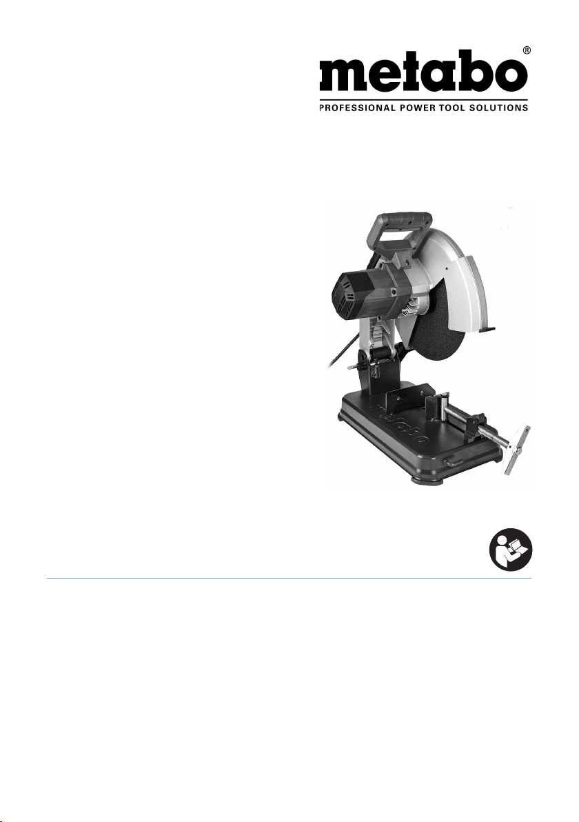
CS 22-355
CS 24-355 S
de Originalbetriebsanleitung 5
en Original instructions 5
en Original instructions 11
fr Notice originale 17
nl Oorspronkelijke gebruiksaanwijzing 23
it Istruzioni originali 29
es Manual original 35
pt Manual original 42
sv Bruksanvisning i original 48
fi Alkuperäiset ohjeet 53
zh 使用说明 11
no Original bruksanvisning 59
da Original brugsanvisning 64
pl Instrukcja oryginalna 70
el Πρωτότυπες οδηγίες χρήσης 76
hu Eredeti használati utasítás 83
ru Оригинальное руководство по
эксплуатации 89
www.metabo.com
Page 2
11
17
10
9
8
7
6
5
4
3
10
12
2
1
13
14
15
16
2
2
Page 3
13.
U V 220-240 110 220-240
I A 10 15 10,5
D
max
H
max 90°
H
P
1
P
2
n
0
x B x d
max45°
W 2300 1600 2400
W 1560 1050 1650
-1
min
(rpm)
mm (in)
mm
(in)
mm
(in)
*1) Serial Number:
01786..
4000 4000 4000
355 x 3 x 25,4 (14 x
132 (5
120 x 120 (4
208 x 100 (8
150 x 150 (5
128 (5
115 x 115 (4
115 x 107 (4
115 x 115 (4
3
/
3
/16)
23
/32 x 4 23/32)
3
/16 x 3 15/16)
29
/32 x 5 29/32)
1
/32)
17
/32 x 4 17/32)
17
/32 x 4 7/32)
17
/32 x 4 17/32)
32
x 1)
CS 22-355 CS 24-355 S
*1) Serial Number:
01787..
L
max
mm (in) 248 (9 3/4 )
m kg (lbs) 16,8 (37)
a
hw/Khw
L
pA/KpA
L
WA/KWA
*2) 2014/30/EU, 2006/42/EC, 2011/65/EU
*3) EN 62841-1:2015, EN 62841-3-10:2015/AC:2016, EN IEC 63000:2018
2021-03-08, Bernd Fleischmann
Direktor Produktentstehung & Qualität (Vice President Product Engineering & Quality)
m/s
2
3,4 / 1,5
dB(A) 91 / 3
dB(A) 104 / 3
*4) Metabowerke GmbH - Metabo-Allee 1 - 72622 Nuertingen, Germany
3
3
Page 4
B
D d
A
B
D = 350 mm
B = 3 mm
d = 25,4 mm
n
= 4.365 min-1
max
D = 350 mm
B = 3 mm
d = 25,4 mm
n
= 4.365 min-1
max
10.
A 36-R: 6.16343
A 30-R: 6.16327
A 36-S: 6.16339
D = 350 mm
C
4
4
d = 25,4 mm
= 4.365 min-1
n
max
B = 3 mm
A 24-M: 6.16338
Page 5
Original instructions
1. Conformity Declaration
We declare under our sole responsibility: These
metal chop saws, identied by type and serial
number *1), comply with all relevant requirements
of the directives *2) and standards *3). Technical
le at *4) - see page 3.
For UK only:
We as manufacturer and authorized person to
compile the technical le, see *4) on page 3,
hereby declare under sole responsibility that these
metal chop saws, identied by type and serial
number *1) on page 3, fulll all relevant provisions of
following UK Regulations S.I. 2016/1091, S.I. 2008/
1597, S.I. 2012/3032 and Designated Standards
EN 61029-1:2009+A11:2010, EN 61029-210:2010+A11:2013, EN IEC 63000:2018.
2. SpeciedUse
When tted with original Metabo cutting discs, the
metal cutter is appropriate for dry cutting of steel,
non-ferrous metals, iron and cast moulds, and
similar materials.
Do not use diamond cut-o wheels.
The user bears sole responsibility for damage
caused by improper use.
Generally accepted accident prevention
regulations and the enclosed safety information
must be observed.
3. General Safety Instructions
For your own protection and for the
protection of your electrical tool, pay
attention to all parts of the text that are
marked with this symbol!
WARNING – Reading the operating
instructions will reduce the risk of injury.
WARNING–Readallsafetywarnings,
instructions,illustrationsand
specicationsprovidedwiththispowertool.
Failure to follow all instructions listed below may
result in electric shock, re and/or serious injury.
Saveallwarningsandinstructionsforfuture
reference. Pass on your electrical tool only
together with these documents.
4. Special Safety Instructions
4.1 Cut-omachinesafetywarnings
a) Position yourself and bystanders away from the
plane of the rotating wheel. The guard helps to
protect the operator from broken wheel fragments
and accidental contact with wheel.
b) Use only bonded reinforced cut-o wheels for
your power tool. Just because an accessory can
ENGLISH en
be attached to your power tool, it does not assure
safe operation.
c) The rated speed of the accessory must be at
least equal to the maximum speed marked on the
power tool. Accessories running faster than their
rated speed can break and y apart.
d) Wheels must be used only for recommended
applications. For example: do not grind with the side
of a cut-o wheel. Abrasive cut-o wheels are
intended for peripheral grinding, side forces applied
to these wheels may cause them to shatter.
e) Always use undamaged wheel anges that are
of correct diameter for your selected wheel. Proper
wheel anges support the wheel thus reducing the
possibility of wheel breakage.
f) The outside diameter and the thickness of your
accessory must be within the capacity rating of
your power tool. Incorrectly sized accessories
cannot be adequately guarded or controlled.
g) The arbour size of wheels and anges must
properly t the spindle of the power tool. Wheels
and anges with arbour holes that do not match
the mounting hardware of the power tool will run
out of balance, vibrate excessively and may cause
loss of control.
h) Do not use damaged wheels. Before each use,
inspect the wheels for chips and cracks. If the
power tool or wheel is dropped, inspect for
damage or install an undamaged wheel. After
inspecting and installing the wheel, position
yourself and bystanders away from the plane of the
rotating wheel and run the power tool at maximum
no load speed for one minute. Damaged wheels
will normally break apart during this test time.
i) Wear personal protective equipment. Depending
on application, use face shield, safety goggles or
safety glasses. As appropriate, wear dust mask,
hearing protectors, gloves and shop apron capable
of stopping small abrasive or workpiece fragments.
The eye protection must be capable of stopping
ying debris generated by various operations. The
dust mask or respirator must be capable of
ltrating particles generated by your operation.
Prolonged exposure to high intensity noise may
cause hearing loss.
j) Keep bystanders a safe distance away from work
area. Anyone entering the work area must wear
personal protective equipment. Fragments of
workpiece or of a broken wheel may y away and
cause injury beyond immediate area of operation.
k) Position the cord clear of the spinning
accessory. If you lose control, the cord may be cut
or snagged and your hand or arm may be pulled
into the spinning wheel.
l) Regularly clean the power tool’s air vents. The
motor’s fan can draw the dust inside the housing
and excessive accumulation of powdered metal
may cause electrical hazards.
m) Do not operate the power tool near ammable
materials. Do not operate the power tool while
5
Page 6

en ENGLISH
placed on a combustible surface such as wood.
Sparks could ignite these materials.
n) Do not use accessories that require liquid
coolants. Using water or other liquid coolants may
result in electrocution or shock.
4.2 Kickbackandrelatedwarnings
Kickback is a sudden reaction to a pinched or
snagged rotating wheel. Pinching or snagging causes
rapid stalling of the rotating wheel which in turn
causes the uncontrolled cutting unit to be forced
upwards toward the operator.
For example, if an abrasive wheel is snagged or
pinched by the workpiece, the edge of the wheel that
is entering into the pinch point can dig into the
surface of the material causing the wheel to climb out
or kick out. Abrasive wheels may also break under
these conditions.
Kickback is the result of power tool misuse and/or
incorrect operating procedures or conditions and can
be avoided by taking proper precautions as given
below.
a) Maintain a rm grip on the power tool and position
your body and arm to allow you to resist kickback
forces. The operator can control upward kickback
forces, if proper precautions are taken.
b) Do not position your body in line with the rotating
wheel. If kickback occurs, it will propel the cutting unit
upwards toward the operator.
c) Do not attach a saw chain, woodcarving blade,
segmented diamond wheel with a peripheral gap
greater than 10 mm or toothed saw blade. Such
blades create frequent kickback and loss of control.
d) Do not „jam“ the wheel or apply excessive
pressure. Do not attempt to make an excessive depth
of cut. Overstressing the wheel increases the loading
and susceptibility to twisting or binding of the wheel in
the cut and the possibility of kickback or wheel
breakage.
e) When the wheel is binding or when interrupting a
cut for any reason, switch o the power tool and hold
the cutting unit motionless until the wheel comes to a
complete stop. Never attempt to remove the wheel
from the cut while the wheel is in motion otherwise
kickback may occur. Investigate and take corrective
action to eliminate the cause of wheel binding.
f) Do not restart the cutting operation in the
workpiece. Let the wheel reach full speed and
carefully re-enter the cut. The wheel may bind, walk
up or kickback if the power tool is restarted in the
workpiece.
g) Support any oversized workpiece to minimize the
risk of wheel pinching and kickback. Large
workpieces tend to sag under their own weight.
Supports must be placed under the workpiece near
the line of cut and near the edge of the workpiece on
both sides of the wheel.
4.3 AdditionalSafetyInstructions
Always wear eye protection and hearing
protection. Put on other protective gear if
necessary, such as dust masks, gloves,
6
helmet and apron. When judging if face or dust
masks are necessary, take into consideration
whether the workpiece to be machined or its coating
are potentially harmful to health. Put on protective
clothing in case of doubt.
Wear ear protectors when working for long periods of
time. High noise levels over a prolonged period of
time may aect your hearing.
Do not work with magnesium.
Do not use power tools in a damp or wet
environment.
Do not use the machine in environments where there
is the risk of explosion, in which sparks can cause
re, explosions or the like.
Do not use saw blades.
Always ensure the metal cut-o machine is stable on
a at surface; when using the cut-o machine on
a workbench, always attach the metal cut-o
machine with appropriately long, sturdy screws.
Danger of crushing! Do not reach into the area of the
joint when lowering the lever!
Never operate the machine without a protective
hood (7).
Always tilt protective hood (7) all the way down.
Be sure that the movable protective hood (7) is not
jammed. It must be able to move.
Check the power tool for potential damage.
-Before continuing to use the power tool, protective
mechanisms or lightly damaged parts must be
carefully inspected for correct operation.
-Damaged protective mechanisms and parts must be
repaired or replaced by an approved specialist
workshop, as long as nothing else is specied in the
instruction manual.
Machine malfunctions, incl. protective hoods or
cutting discs, must immediately be reported when
they occur. The malfunction must be properly
remedied.
Regularly check the connection lead of the power
tool and have it repaired by an approved expert,
should it be damaged.
Regularly check extension cables and replace them,
should they be damaged.
Use only three-conductor cables.
Keep the handles dry, clean and free of oil and
grease.
Do not use a low-power machine for demanding jobs.
Adhere to the instructions for lubrication and tool
replacement.
Store the machine in a dry, high or secured place,
outside the reach of children.
When working in dusty conditions, ensure that
ventilation openings are not blocked. Should it be
necessary to remove the dust, rst disconnect the
power tool from the mains.
Page 7

In case of extreme dust deposits, the machine
cleaning cycles must be shortened and/or a residualcurrent-operated circuit-breaker (RCCB) must be
connected upstream.
When the machine is shut down via the RCCB circuit-
breaker, it must be checked and cleaned.
Use only cutting discs recommended by the
manufacturer that comply with the specications of
the respective safety standards for grinding materials,
e.g. EN 12413.
Caution! The use of other tools and accessories can
result in a risk of injury.
Cutting discs must be stored in accordance with
manufacturer specications and handled carefully.
Wear protective gloves when handling cut-o
wheels.
Store the cutting disc in a dry place. With cutting
discs for dry cuts, the strength may be reduced by
moisture or water.
Handle the cutting disc with caution. Protect the
cutting disc from jolts or impacts.
Always use equipment that fulls the following
minimum requirements:
Only cutting discs with resinoid bonding and bre
reinforcement can be used. The maximum rotations
per minute (rpm) of the cutting disc must not be lower
than the machine idling speed.
Adhere to the maximum cutting disc diameter (see
technical data).
Use no cutting discs that are thicker than 3 mm (3/
32").
The bore of the cutting disc must t the toolholder
without any clearance. Do not use adapters or
reducers.
Observe the specications of the tool or accessory
manufacturer!
Adhere to the cutting disc instruction manual.
Use elastic cushioning layers if they have been
supplied with the sanding media and if required.
Be particularly cautious with the parts that are
connected to the cutting disc. Take care not to
damage the spindle, ange or screw. Damage to
these parts can cause the cutting disc to break.
It must be ensured that mounted cutting discs are
installed in accordance with the manufacturer
specications.
Before use, make sure the cutting discs are correctly
xed and fastened, and operate the machine in idling
mode for 30 s. Immediately switch o the machine if
strong vibrations or other malfunctions occur. Should
they occur, inspect the machine to nd the cause.
When the cutting disc is used up to the wear limit (1/
3 of the outer diameter), replace the cutting disc.
Pull the plug out of the plug socket before any
adjustments or servicing are performed.
The cutting disc continues to rotate after the machine
has been switched o.
ENGLISH en
Engage the spindle locking knob (8) only when the
motor is inoperative.
Do not touch the rotating cutting disc.
Danger of injury!
When the cutting disc vibrates too strongly in idling
mode, it can lead to breakage. In case of irregularities
during use, immediately switch o the machine and
have it repaired.
Secure the workpiece. Use the vice to secure the
workpiece.
Do not try to saw extremely small workpieces.
During machining, the workpiece must be rmly
supported and secured against moving.
Long workpieces must be suciently supported.
Begin cutting only after having reached the max.
rpm.
Use only the cutting edge of the cutting disc to cut.
Do not use the lateral surface of the cutting disc for
grinding jobs.
When working on workpieces with curves or inclined
surfaces, make sure that no lateral pressure is
applied to the cutting disc.
Ensure that sparks produced during work do not
constitute a risk to the user or other personnel and
are not able to ignite inammable substances.
Endangered areas must be protected with
ameresistant covers.
Make sure that re-risk areas are always provided
with suitable re extinguishers.
The workpiece can be very hot after having been
machined. Caution, risk of burning!
Reducingdustexposure:
WARNING - Some dust created by power
sanding, sawing, grinding, drilling, and other
construction activities contains chemicals known to
cause cancer, birth defects or other reproductive
harm. Some examples of these chemicals are:
- Lead from lead-based paints,
- Crystalline silica from bricks and cement and other
masonry products, and
- Arsenic and chromium from chemically treated
lumber.
Your risk from these exposures varies, depending on
how often you do this type of work. To reduce your
exposure to these chemicals: work in a well ventilated
area, and work with approved safety equipment, such
as those dust masks that are specially designed to
lter out microscopic particles.
This also applies to dust from other materials such as
some timber types (like oak or beech dust), metals,
asbestos. Other known diseases are e.g. allergic
reactions, respiratory diseases. Do not let dust enter
the body.
Observe the relevant guidelines and national
regulations for your material, sta, application and
place of application (e.g. occupational health and
safety regulations, disposal).
7
Page 8
en ENGLISH
Collect the particles generated at the source, avoid
deposits in the surrounding area.
Use suitable accessories for special work. In this way,
fewer particles enter the environment in an
uncontrolled manner.
Use a suitable extraction unit.
Reduce dust exposure with the following measures:
- do not direct the escaping particles and the exhaust
air stream at yourself or nearby persons or on dust
deposits,
- use an extraction unit and/or air puriers,
- ensure good ventilation of the workplace and keep
clean using a vacuum cleaner. Sweeping or blowing
stirs up dust.
- Vacuum or wash the protective clothing. Do not
blow, beat or brush.
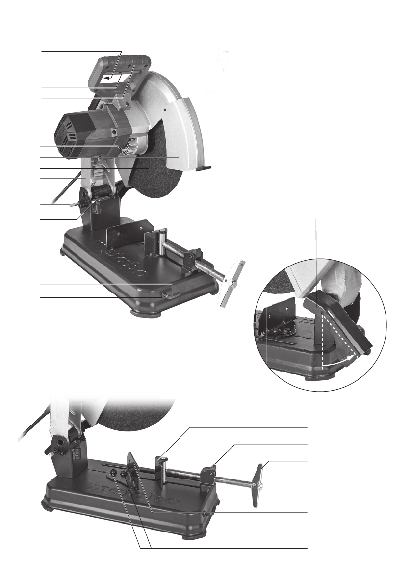
5. Overview
See page 2.
1 Wrench depot
2 Wrench for replacing cutting discs and
adjustment work
3 Cutting depth limiter
4 Transportation lock
5 Lever
6 Cutting disc *
7 Safety cover
8 Spindle locking knob
9 Handle
10 Trigger switch
11 Safety switch (for protection against accidental start)
12 Spark deector plate
13 Vice
14 Lever for quick adjustment
15 Crank
16 Stopper
17 Screws (for setting cutting angle and maximum
clamping width)
* not in scope of delivery
6. Commissioning
Before plugging in, check to see that the rated
mains voltage and mains frequency, as
specied on the rating label, match your power
supply.
Always install an RCD with a max. trip current
of 30 mA upstream.
The machine can be supplied only with the mains
voltage and frequency specied on the type plate.
When, for example, a 120 V machine is supplied with
230 V of mains voltage, the cutting discs and the
machine can be damaged by surpassing the max. rpm.
All screws must be screwed tight. Screw the
screw tight with the provided wrench to fasten
the cutting disc and check if all other screws are
also screwed tight.
Sparkdeectorplate(12):
Before commissioning the spark deector plate, tilt
it to the mark.
8
7. Use
7.1 Settingcuttingdepth
For presetting the desired cutting depth, e.g. for
several cuts with the same cutting depth.
Settingthecuttingdepthlimiter(3):
- Free the lock nut.
- Set the hexagon screw for the desired cutting
depth.
- Retighten the lock nut.
7.2 Vice
Clamp the workpiece tightly into the vice (13).
Setting the cutting angle:
- Loosen the two screws (17) on the stopper (16).
- Set the desired cutting angle.
- Retighten the two screws (17).
Conguringthemaximumclampingwidth:
The stopper can be set for 3 positions.
- Additionally, remove the two screws (17).
- Shift the stopper (16) to the rear / middle / forward
position.
- Fasten the stopper (16) again with the two screws
(17).
Clampingtheworkpiece:
- For quick adjustment, turn the lever (14) forwards
and push the crank (15) towards the workpiece.
- Push the lever (14) backwards and tight turn the
crank (15) clockwise to clamp the workpiece.
7.3 Cuttingthroughaworkpiece
Danger of crushing! Do not reach into the area
of the joint when lowering the lever!
• Do not begin cutting until the machine has
reached its maximum rpm.
• Slowly lower the cutting disc onto the workpiece
and conduct the cut with little contact pressure.
• After nishing the job, put the lever into the
starting position.
• After a complete cut, switch o the machine,
allow the motor to come to a complete standstill
and only then prepare the next cutting job. The
removal or insertion of workpieces while the
cutting disc is rotating can lead to injury.
• Do not work with too much contact pressure,
since the cutting disc can otherwise quickly
become worn out, or the machine or workpiece
can be damaged.
7.4 Switchingonando
Switchingon: Press and hold safety switch (11),
press the trigger (10).
Switchingo: release the trigger switch (10).
7.5 Transport
For transport, turn the lever (5) all the way down
and stop by actuating the transportation lock (4).
Note: To lock the lever, it is necessary to turn the
cutting depth limiter (3) to a lower position. See
section 7.1.
Page 9
8. Maintenance
Disconnect the mains plug before starting
any conversion or maintenance work!
Engage the spindle locking knob (8) only
when the motor is inoperative.
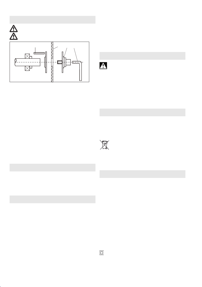
8
a
bc
Removingthecuttingdisc:
- Press lever for spindle locking knob (8) to the right
and turn the cutting disc by hand until the spindle
locking knob is felt to engage.
- Use the wrench (c) to remove the screw with
clamping ange (b) anti-clockwise.
- Remove cutting disc.
Fittingthecuttingdisc:
- Put on new cutting disc (a).
- Fit the screw with clamping ange (b).
- Use wrench (c) to lock spindle and tighten screw
with clamping ange (b).
- Check whether the spindle locking knob (8) is
completely disengaged again.
- Clean the dirty machine and remove the grinding
dust.
Regular maintenance:
Oil the following parts at least once a month:
movable parts of the vice.
9. Troubleshooting
CS 22-355: Switching on procedures produce brief
reductions in voltage. Unfavourable power
conditions can be detrimental to other devices.
Power impedances smaller than 0.24 ohm should
not cause any malfunction.
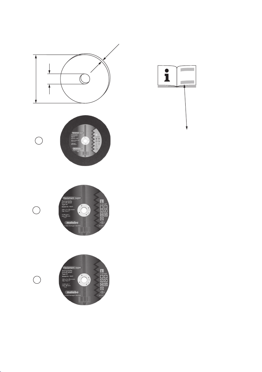
10. Accessories
Use only genuine Metabo accessories.
If you need any accessories, check with your
dealer.
For dealers to select the correct accessory, they
need to know the exact model designation of your
power tool.
See page 3.
A Cutting discs: Quality class A 36-R
"FlexiamantSuper"inox.
Special cutting disc of medium hardness for
stainless steel.
High cutting performance with long lifetime.
B Cutting discs: Quality class A 30-R / A 36-S
"FlexiamantSuper"steel.
Good cutting performance in steel, with good
lifetime.
ENGLISH en
Hard version for powerful machines.
A 36-S: with an interior fabric for quick cuts.
C Cutting discs: Quality class A 24-M
"FlexiamantSuper"steel.
High cutting performance in steel, with good lifetime.
Soft version for less powerful machines.
For a complete range of accessories, see
www.metabo.com or the main catalogue.
11. Repairs
Repairs to electrical tools must be carried out by
qualied electricians ONLY!
A defective mains cable must only be replaced with a
special, original mains cable from metabo, which is
available only from the Metabo service.
If you have Metabo electrical tools that require
repairs, please contact your Metabo service centre.
For addresses see www.metabo.com.
You can download spare parts lists from
www.metabo.com.
12.EnvironmentalProtection
The generated grinding dust may contain harmful
substances. Dispose appropriately.
Observe national regulations on environmentally
compatible disposal and on the recycling of
disused machines, packaging and accessories.
Only for EU countries: Never dispose of
power tools in your household waste! In
accordance with European Directive 2012/
19/EU on waste electrical and electronic equipment
and its implementation in national law, used
electrical tools must be collected separately and
handed in for environmentally compatible recycling.
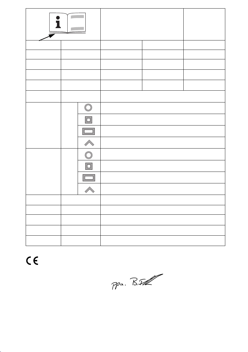
13. TechnicalSpecications
Explanatory notes on the specications on page 3.
Changes due to technological progress reserved.
U = Voltage
I = Current
P1 = Rated input
P2 = Power output
n0 = No load speed
Cutting disc dimensions:
D
=Maximum outer diameter
max
B =Wheel thickness
d =Bore
H
= max. cutting diameter 90°
max 90°
H
= max. cutting diameter 45°
max 45°
L
= Max. vice opening
max
m = Weight without mains cable
Measured values determined in conformity with EN
62841.
Machine in protection class II
~ AC Power
The technical specications quoted are subject to
tolerances (in compliance with the relevant valid
standards).
9
Page 10

en ENGLISH
Emissionvalues
These values make it possible to assess the
emissions from the power tool and to compare
dierent power tools. Depending on the operating
conditions, the condition of the power tool or the
accessories, the actual load may be higher or lower.
For assessment purposes, please allow for breaks
and periods when the load is lower. Based on the
adjusted estimates, arrange protective measures for
the user e.g. organisational measures.
Vibration total value (vector sum of three directions)
determined in accordance with EN 62841:
ahw = Vibration emission value
Khw = Uncertainty (vibration)
Typical A-eective perceived sound levels:
LpA = Sound-pressure level
LWA = Acoustic power level
KpA, KWA = Uncertainty
During operation the noise level can exceed
80 dB(A).
Wear ear protectors!
10
Page 11
使用说明
1. 一致性声明
作为唯一责任人,我们特此声明:我公司金属裁断
锯产品按型号和序列号标识*1),符合指令*2) 和标
准*3) 的所有相关要求。相关技术文件 *4) - 请参见
第 3 页。
以下声明仅针对英国:
作为制造商和获授权编写技术文件(请参见第
3 页的 *4))的人员,我们特此声明:我公司
金属裁断锯产品按型号和序列号标识(请参见第 3 页
的 *1)),符合英国条例 S.I. 2016/1091、S.I. 2008/
1597 和 S.I. 2012/3032 以及指定标准 EN 61029-
1:2009+A11:2010、EN 61029-2- 10:2010+A11:2013
和 EN IEC 63000:2018 中的所有相关规定。
2. 规定用途
当安装麦太保原厂切割盘时,金属切刀适用于对钢
材、有色金属、铁和铸造模具以及类似材料进行干
切削。
请勿使用金刚石切断砂轮。
因使用不当造成的损坏由用户承担全部责任。
必须遵守通用事故预防规章和随附的安全资料。
3. 一般安全说明
为了保护您自己和保护您的电动工具,请
注意带有该符号标记的文本的所有部分!
警告 – 仔细阅读使用说明可降低受伤风险。
警告 - 请仔细阅读本电动工具附带的所有安全
警告、说明、图示及规格。不遵照以下警告和
说明会导致电击、着火和/或严重伤害。
保存所有警告和说明书以备查阅。转交电动工具时,
请一并转交这些文件。
4. 特殊安全说明
4.1 切断机安全警告
a) 确保本人和旁观者避开旋转砂轮所在平面。护罩
可保护操作者不受破损砂轮碎片伤害,避免与砂轮
意外接触。
b) 仅限在电动工具上使用黏合增强型切断砂轮。即使
配件可安装在电动工具上,也不能保证安全作业。
简体中文 zh
c) 配件的额定转速须至少等于电动工具上标注的最
大转速。配件如以大于额定转速的速度工作,则会
破裂飞散。
d) 砂轮必须仅用于推荐的应用。例如:请勿使用
切断砂轮侧面进行研磨。研磨切断砂轮旨在用于
周边磨削,施加在侧面的作用力可能导致砂轮
碎裂。
e) 务必使用完好的砂轮法兰,并且法兰直径与所选
砂轮相匹配。适合的砂轮法兰可支承砂轮,从未降
低砂轮破裂的可能性。
f) 配件外直径和厚度须在电动工具的额定值范围
以内。尺寸不当的配件无法得到适当的保护或
控制。
g) 砂轮和法兰的轴尺寸必须符合电动工具的主轴尺
寸。若砂轮和法兰轴孔与电动工具安装零件不匹
配,则可能会导致不平衡、引发剧烈振动并甚至造
成失控。
h) 不得使用损坏的砂轮。每次使用砂轮之前,应
检查其是否存在缺口和裂痕。如果电动工具或砂
轮坠落,则请查看损坏情况,或者安装完好的砂
轮。检查、安装砂轮之后,请您本人和旁观者避
开旋转砂轮所在平面,并以最大空载转速运行电
动工具 1 分钟。通常,损坏的砂轮在此测试时间
即会破裂。
i) 穿戴个人防护装备。根据不同的应用,可使用面
罩、护目镜或安全眼镜。也可视情况佩戴防尘面
罩、听力防护设备、隔挡磨料或工件微小碎片的手
套和车间围裙。护目设备必须能够阻隔各式作业中
形成的飞溅碎片。防尘面罩必须能够滤除作业中产
生的颗粒。长时间置身高强度噪声之中会导致听力
下降。
j) 旁观者与工作区应保持安全距离。任何人进入工
作区时都必须佩戴个人防护装备。工件或破损砂轮
的碎片飞溅,会在作业附近区域之外造成伤害。
k) 电线应当远离旋转的配件。一旦失控,电线可
能会被割断或缠结,人手或手臂则可能卷入旋转
的砂轮。
l) 定期清理电动工具的通风口。电机风扇可能会将
粉尘吸入机壳,而过多金属粉末沉积会引发电气
危险。
m) 切勿在可燃物附近操作电动工具。切勿在木头等
易燃表面上操作电动工具。火花会引燃这些物质。
11
Page 12

zh 简体中文
n) 切勿使用需要液体冷却剂的配件。使用水或其
它液体冷却剂,可能会导致触电或电击事故的
发生。
4.2 反弹和相关警告
反弹是因为旋转砂轮卡住或缠结而突发的反作用。
卡住或缠结致使旋转砂轮迅速停止,随之使得失控
的切割装置受力向上朝向操作者。
例如,砂轮被工件缠结或卡住,卡住点上的砂轮边
沿会切入物料表面,致使砂轮脱出或弹出。在此种
情况下,砂轮也可能破裂。
反弹是电动工具误用和∕或不正确操作工序或条件
的结果,可通过采取下列的适当预防措施加以
避免:
a) 保持紧握电动工具,并让身体和手臂处于能够抵
御反弹力的位置。如果采取的预防措施适当,操作
者即能控制向上反弹力。
b) 请勿将身体直对旋转的砂轮。如果发生反弹,砂
轮会将切割装置向上推向操作者。
c) 不得附装锯链、木雕刀片、周边间隙大于 10mm
的分段金刚石砂轮或者带齿锯片。此类锯片会导致
频繁的反弹和失控。
d) 请勿“夹住”切断砂轮或施加过大压力。不得尝
试进行过深的切割。砂轮承受过大应力,会造成负
载增加,从而使砂轮在切割过程更易缠结或粘连,
发生反弹或砂轮破裂的可能性上升。
e) 每当砂轮粘连或者出于任何原因中断切割时,应
切断电动工具并保持切割装置静止,直至砂轮完全
停止。砂轮转动期间,切勿尝试将砂轮从切口上移
开,否则会产生反弹。调查并采取校正措施消除砂
轮粘连的成因。
f) 请勿在工件上重启切割操作。应让砂轮达
到全速后,再小心地重新进入切割。如果在工件
上重启电动工具,则砂轮会发生粘连、脱出或
反弹。
g) 对任何超大工件加以支撑,可将砂轮卡住和反弹
的危险降至最低限度。大型工件受自身重量影响而
容易下垂。必须在靠近切割线处和砂轮两侧靠近工
件边缘处的工件下方放置支承。
4.3 附加安全说明
请务必佩戴护目镜和听力防护装置。必要
时穿戴防尘面具、手套、头盔和围裙等其
他防护装备。置于是否需要佩戴面罩或防
尘面具,取决于要加工的工件或其涂层是否可能危
害健康。如果不确定,请穿好防护服。
长时间工作时,需配戴护耳器。长期接触高强度噪
音可能会影响您的听力。
请勿使用镁。
请勿在潮湿环境中使用电动工具。
请勿在有爆炸危险的环境中使用该工具,否则产生
的火花会引起火灾、爆炸等危险。
请勿使用锯片。
始终确保金属切断机平稳置于平面上;在工作台上
使用切断机时,请务必使用长度合适的坚固螺钉来
固定金属切断机。
存在挤压危险!向下放杆时,请勿触及接合区域!
切勿在未佩戴防护罩 (7) 的情况下操作工作。
始终向下倾斜防护罩 (7)。
确保活动防护罩 (7 ) 不会被卡住。它必须能够
移动。
检查电动工具是否有潜在的损坏。
- 继续使用电动工具之前,必须先仔细检查保护机
构或轻微损坏的零件能否正常工作。
- 除非说明书中另有说明,否则损坏的保护机构和
零件都必须由经批准的车间专员进行维修或
更换。
工具(包括防护罩或切割盘)发生故障时必须立即
上报。并且,故障情况必须得到妥善补救。
定期检查电动工具的连接线,如果发现损坏,应安
排经批准的专业人员进行维修。
定期检查延长电缆,如有损坏,应予以更换。
仅限使用三芯电缆。
确保手柄干燥、清洁、无油污。
请勿将低功率工具用于要求严苛的作业。
遵守润滑和工具更换说明。
将工具存放在干燥、位置较高或安全的地方,确保
儿童无法触及。
在粉尘较多的条件下作业时,应确保通风口未阻
塞。如果需要清除灰尘,请先断开电动工具的
电源。
12
Page 13

简体中文 zh
如果灰尘堆积严重,必须缩短工具清洁周期和/或在
上游连接一个剩余电流动作断路器 (RCCB)。
RCCB 断路器关闭工具后,必须对工具进行检查和
清洁。
仅限使用制造商推荐的符合磨削材料相关安全标准
(例如 EN 12413)规格的切割盘。
注意!使用其他工具和配件可能会造成人员
受伤。
切割盘必须按照制造商规定进行存放,搬运时应小
心谨慎。
操作切断砂轮时,请戴好防护手套。
将切割盘存放在干燥处。对于进行干切削的切割
盘,湿气或水分可能会降低切削强度。
请小心操作切割盘。保护切割盘免受震动或
冲击。
务必确保使用的设备满足以下最低要求:
仅限使用带树脂黏合和纤维增强的切割盘。切割
盘的每分钟转数 (rpm) 最大值不得低于工具空转
速度。
遵循最大切割盘直径(请参见技术数据)。
请勿使用厚度超过 3 mm (3/ 32") 的切割盘。
切割盘的孔径必须与刀架完全吻合。请勿使用转接
器或减径管。
请遵循工具或配件制造商的规格说明!
遵循切割盘说明书。
如果制造商为打磨介质配备了弹性缓冲层,请在必
要时使用。
对于连接到切割盘的零件要格外小心,不要损
坏主轴、法兰或螺钉,否则可能会导致切割盘
破裂。
必须确保按照制造商规定来安装切割盘。
使用前,应确保已正确安装和紧固切割盘,并在
空转模式下运行工具 30 秒。如果出现剧烈振动或
其他故障,请立即关闭工具。随后检查工具,找
出原因。
当切割盘达到磨损极限(外径的 1/3)时,请更换
切割盘。
调试或维修工具前,请将主电源拔下。
工具关闭后,切割盘会惯性旋转一段时间。
请在电机不工作后再接合主轴锁定旋钮 (8)。
请勿触摸正在旋转的切割盘。
存在受伤危险!
如果切割盘在空转模式下振动过于剧烈,可能会导
致破裂。如果使用过程中出现异常,请立即关闭工
具并进行维修。
固定工件。使用台钳固定工件。
请勿尝试锯切极小的工件。
加工期间,必须牢固支撑和固定好工件,以防
移动。
长工件必须有足够的支撑。
达到最大 rpm 后才能开始切割。
仅限使用切割盘的切割边缘进行切割。请勿使用切
割盘的侧面进行磨削作业。
加工有曲线或倾斜表面的工件时,请确保切割盘没
有受到侧向压力。
确保工作期间产生的火花不会对用户或其他人员造
成威胁且不会点燃易燃物质。危险区域必须使用防
火材料覆盖。
保证在易于着火的区域备有合适的灭火器。
工件加工后可能会很烫。小心灼伤!
减少粉尘暴露:
警告 - 打磨、锯切、研磨、钻孔和其他制造活
动产生的一些粉尘中含有已知会导致癌症、出
生缺陷或其他生殖伤害的化学物质。此类化学物质
的一些示例包括:
-铅基涂料中的铅;
-砖、水泥和其他砖石产品中的结晶二氧化硅;以及
-经过化学处理的木材中的砷和铬。
这些化学物质的暴露风险取决于您执行此类工作的
频率。为降低对这些化学物质的暴露程度:在通风
良好的区域作业,并穿戴经认可的防护装备,例如
那些专为过滤微小颗粒而设计的防尘面罩等。
这同样适用于来自其他材料的粉尘,例如某些木材
(例如橡木或山毛榉粉尘)、金属、石棉。其他已
知疾病包括过敏反应、呼吸系统疾病。切勿吸入这
些灰尘。
遵守物料、员工、应用和应用地点的相关准则和国
家/地区法规(例如,职业卫生与安全法规、废物处
理规范等)。
13
Page 14
zh 简体中文
从源头收集产生的颗粒,避免在周围环境中沉积。
对于特殊作业,使用适当的配件。这样一来,将可
以减少进入环境中的微粒。
使用适当的除尘装置。
通过以下措施降低粉尘暴露程度:
- 请勿将颗粒和废气流朝向自己或附近人员逃逸或
排放,也不要将其朝向沉积的粉尘。
- 使用除尘装置和/或空气净化器。
- 确保工作区域通风良好,使用真空吸尘器保证工
作区域的清洁。吹扫会使粉尘飞散。
- 使用吸尘器或水清洁防护服。请勿吹、打或刷。
5. 概述
请参见第 2 页。
1 扳手仓
2 用于更换切割盘和调整工作的扳手
3 切割深度限制器
4 运输锁
5 杆
6 切割盘*
7 安全罩
8 主轴锁定旋钮
9 手柄
10 触发开关
11 安全开关(用于防止意外启动)
12 火花导流板
13 台钳
14 快速调整杆
15 曲柄
16 限位器
17 螺钉(用于设定切割角度及最大夹紧宽度)
* 不在交付范围内
6. 调试
接通电源前,请查看额定电源电压及频率(标
在额定值标签上)是否与现有的电源相符。
务必在上游安装一个最大脱扣电流为 30 mA
的 RCD。
工具只能使用铭牌上指定的电源电压和频率。例
如,当 120 V 工具使用 230 V 的电源电压时,切割
盘和工具可能会因超过最大 rpm 而损坏。
务必拧紧所有螺钉。使用随附的扳手拧紧螺
钉,紧固切割盘,然后检查所有其他螺钉是否
也已拧紧。
火花导流板(12):
调试火花导流板之前,请先将其倾斜至标记处。
14
7. 使用
7.1 设置切割深度
用于预设所需的切割深度,例如在进行多次切割深
度相同的切割时。
设置切割深度限制器(3):
- 松开锁紧螺母。
- 将六角螺钉调整到所需的切割深度。
- 重新拧紧锁紧螺母。
7.2 台钳
将工件置于台钳 (13) 中夹紧。
设置切割角度:
- 松开限位器 (16) 上的两个螺钉 (17)。
- 设置所需的切割角度。
- 重新拧紧两个螺钉 (17)。
配置最大夹紧宽度:
限位器可设置 3 个位置。
- 然后,拆下两个螺钉 (17)。
- 将限位器 (16) 移至后/中/前位置。
- 用两个螺钉 (17) 再次紧固限位器 (16)。
夹紧工件:
- 若要快速调整,可向前转动杆 (14) 并将曲柄 (15)
推向工件。
- 向后推动杆 (14),顺时针拧紧曲柄 (15),以便夹
紧工件。
7.3 切割工件
存在挤压危险!向下放杆时,请勿触及接合区域!
• 请在工具达到最大 rpm 之后再开始切割。
• 缓慢将切割盘降低到工件上,用很小的接触压力
进行切割。
• 完成作业后,将杆置于起始位置。
• 完成切割后,关闭工具,等待电机完全停止,然
后准备下一次切割作业。请勿在切割盘旋转时取
下或插入工件,否则可能会受伤。
• 请勿在接触压力过大的情况下作业,否则切割盘
会磨损得很快,甚至可能导致工具或工件损坏。
7.4 开启与关闭
开关通:按住安全开关
开关断:释放触发开关 (10)。
7.5 运输
运输时,请将杆 (5) 向下转动到尽头,并通过启动
运输锁 (4) 停止。
(11)
,然后按下触发开关
(10)
。
Page 15
简体中文 zh
注意:若要锁定杆,必须将切割深度限制器 (3) 转
到较低的位置。请参见章节 7.1。
8. 维护
开始任何转换或维护工作前,请先断开电源
插头!
请在电机不工作后再接合主轴锁定旋钮 (8)。
8
a
bc
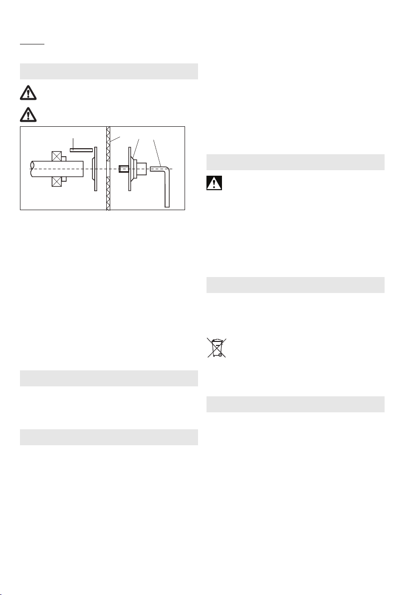
拆下切割盘:
- 向右按主轴锁定旋钮 (8) 的杆,用手转动切割
盘,直到感觉到主轴锁定旋钮卡合到位。
- 用扳手 (c) 逆时针拧下螺钉与夹紧法兰 (b)。
- 取下切割盘。
安装切割盘:
- 放上新的切割盘 (a)。
- 装上螺钉与夹紧法兰 (b)。
- 使用扳手 (c) 锁定主轴并拧紧螺钉与夹紧法兰 (b)。
- 再次检查主轴锁定旋钮 (8) 是否完全脱离。
- 清洁弄脏的工具,并清除研磨粉尘。
定期维护:
每月至少给以下部件上一次油:台钳的活动零件。
9. 故障排除
CS 22-355:接通程序会使电压短暂下降。不适宜
的电源条件可能会对其他设备产生不利影响。电源
阻抗低于 0.24 欧姆时不会导致任何故障。
10. 配件
只能使用麦太保原厂配件。
如果您需要任何配件,请与您的经销商协商。
为了购买正确的配件,请告知经销商您所拥有的电
动工具的准确型号。
请参见第 3 页。
A 切割盘:质量等级 A 36-R
“FlexiamantSuper”不锈钢。
不锈钢专用中硬度切割盘。
切割性能高、使用寿命长。
B 切割盘:质量等级 A 30-R/A 36-S
“FlexiamantSuper”钢材。
钢制切割性能好、使用寿命长。
强力工具的硬版本。
A 36-S:带有适合快速切割的内部结构。
C 切割盘:质量等级 A 24-M
“FlexiamantSuper”钢材。
钢材切割性能高、使用寿命长。
中等工具的软版本。
如需了解全部配件,请访问
www.metabo.com 或参见主目录。
11. 维修
只能由合格的电工修理电动工具!
损坏的电源电缆只能用麦太保服务中心提供的
专用原厂电源电缆更换。
如有麦太保电动工具需要维修,请联系当地的麦太
保服务中心。要获取地址,请访问
www.metabo.com。
并且可从以下网址下载零件列表:
www.metabo.com。
12. 环境保护
产生的研磨粉尘可能包含有害物质。务必适当处置。
有关废弃的工具、包装和配件的环保性处置及回
收,请遵循国家/地区的相关规定。
仅适用于欧盟国家/地区:不得将电动工具与
生活垃圾一同处置!根据关于废旧电气和电
子设备的欧洲指令 2012/19/EU 及其在国家/
地区法律中的实施,必须单独收集并上交用过的电
动工具,以环保方式进行回收利用。
13. 技术规格
有关规格的解释性说明,请参见第 3 页。保留因技
术发展而进行变更的权利。
U = 电压
I = 电流
P1 = 额定输入
P2 = 功率输出
n0 = 空载转速
切割盘尺寸:
D
= 最大外径
max
B = 砂轮厚度
d = 孔径
H
= 最大切割直径 90°
max 90°
H
= 最大切割直径 45°
max 45°
15
Page 16
zh 简体中文
L
= 最大台钳开口
max
m = 不含电源电缆的重量
测量值依照 EN 62841 确定。
工具的防护等级为 II 级
~ 交流电
引用的技术资料皆含有公差值在内(依照相关有效
标准)。
排放值
这些值可用来评估电动工具的排放量,以及比
较不同的电动工具。作业条件以及电动工具或配件
的状况各不相同,实际负载也随之或高或低。当载
荷较低,无法进行评估时,请让工具休息一下。根
据调整后的估计值,为使用者安排保护措施,例如
组织措施。
振动总值(三个方向的矢量和)依据 EN 62841 确定:
ahw = 振动排放值
Khw = 不确定度(振动)
典型 A 荷重声音等级:
LpA = 声压等级
LWA = 声压功率等级
KpA、KWA= 不确定度
操作过程中,噪音水平可能超过 80 dB(A)。
佩戴护耳器!
16
Page 17

Page 18

Page 19

Page 20

170278250 - 1121
170 27 7980 - 0421
Metabowerke GmbH
Metabo-Allee 1
72622 Nuertingen
Germany
www.metabo.com
 Loading...