

Page 1
SBE 521
SBE 550
SBE 561
SB 561
BE 561
B 561
Gebrauchsanleitung .............. Seite
ENG
Operating Instructions...........page
Mode d’emploi ......................page
Gebruiksaanwijzing .........bladzijde
Istruzioni d’uso ................... pagina
Instrucciones de manejo .... página
Instruções de serviço ......... página
Bruksanvisning ....................... sida
Käyttöohje ...............................sivu
Bruksanvisning ....................... side
Betjeningsvejledning .............. side
POL
Instrukcja obsługi ................strona
Οδηγίες χρήσης................Σελίδα
Használati útmutató .............. oldal
Инструкция по использованию.. стр.
170 26 8610 - 0108
5
10
15
20
25
30
35
40
45
50
55
60
65
71
76
Page 2
13
P
1
P
2
W 520 550 560
W 300 320
SBE 521
SBE 550
SBE 561
SB 561
BE 561
B 561
n
0
n
1
ø max.
s max.
/min 0-2600 0-2800 2800 0-2800 2800
/min 1600 1700
mm
(in)
/min.
bpm
47000 50000 - -
12 (1/2“) - -
ø max. mm (in) 20 (3/4“)
ø max. mm (in) 10 (3/8“)
G UNF (in)
Hmm (in)
6,35
(1/4“)
1/2“-20
mkg (lbs) 1,7 (3.7)
D
a
h, ID/Kh, ID
a
h, D/Kh, D
L
pA/KpA
L
WA/KWA
mm
(in)
m/s
m/s
2
28 / 2,0 28 / 2,0 28 / 2,0 28 / 2,0 - -
2
5 / 1,5 5 / 1,5 5 / 1,5 5 / 1,5 5 / 1,5 5 / 1,5
(1 11/16“)
dB(A) 96 / 3 96 / 3 96 / 3 96 / 3 81 / 3 81 / 3
dB(A) 107 / 3 107 / 3 107 / 3 107 / 3 92 / 3 92 / 3
43
6,35
(1/4“)
-
EN 60745
98/37/EG (
Erhard Krauß, Geschäftsführung
© 2008 Metabowerke GmbH, 72622 Nürtingen, Germany
➛
28.12.09), 2006/42/EG (29.12.09➛), 2004/108/EG
2
Page 3
SBE 561, SBE 550, SBE 521, SB 561
7
1
2
3
4
SBE 561, SBE 550, SBE 521, SB 561
5
SBE 561, SBE 550, SBE 521, SB 561
6
SBE 561, SBE 550, SBE 521, BE 561
GRIP, ZU
L
R
ba
SBE 561, SBE 550, SBE 521, BE 561
ba
AUF, RELEASE
8
9
10
3 x
3
Page 4
BA
6.276086.31078
C
6.00890
D
a=80
b=80
6.27106
F
6.30552
6.30553
SBE 561, SBE 550, SBE 521
ALU
ø
mm
4
6
6
8
10
12
16
20
5
6 6 6
a=100
b=100
6.12001
5
E
6.30554
a=86
b=80
6.12003
HG
SBE 561
SBE 550
6.30551
6.30550
1 2 3 4 5 6
SBE 521
1100 1400 1700 2000 2300 2600 .../min
SBE 550,
SBE 561,
1300 1600 1900 2200 2500 2800 .../min
BE 561
50 40 30 20 15 10 %
SBE 521
BE 561
6.31281
4
Page 5
DEUTSCH
D
Gebrauchsanleitung
Sehr geehrter Kunde,
vielen Dank für das Vertrauen, das Sie uns beim Kauf Ihres neuen Metabo Elektrowerkzeugs
entgegengebracht haben. Jedes Metabo Elektrowerkzeug wird sorgfältig getestet und unterliegt den
strengen Qualitätskontrollen der Metabo Qualitätssicherung. Die Lebensdauer eines Elektrowerkzeugs
hängt aber in starkem Maße von Ihnen ab. Beachten Sie bitte die Informationen dieser
Gebrauchsanleitung und der beiliegenden Dokumente. Je sorgsamer Sie Ihr Metabo Elektrowerkzeug
behandeln, umso länger wird es zuverlässig seinen Dienst erfüllen.
Inhalt
1 Konformitätserklärung
2 Bestimmungsgemäße Verwendung
3 Allgemeine Sicherheitshinweise
4 Spezielle Sicherheitshinweise
5Überblick
6 Inbetriebnahme
6.1 Montage des Zusatzhandgriffs
(SBE 561, SBE 550, SBE 521, SB 561)
7 Benutzung
7.1 Verstellen des Bohrtiefenanschlags
(SBE 561, SBE 550, SBE 521, SB 561)
7.2 Ein-/Ausschalten
7.3 Drehzahl vorwählen
(SBE 561, SBE 550, SBE 521, BE 561)
7.4 Umschalten Bohren/Schlagbohren
(SBE 561, SBE 550, SBE 521, SB 561)
7.5 Drehrichtung wählen
(SBE 561, SBE 550, SBE 521, BE 561)
7.6 Werkzeugwechsel
Schnellspann-Bohrfutter Futuro Plus
7.7 Werkzeugwechsel
Zahnkranz-Bohrfutter
7.8 Bohrfutter abnehmen
8 Tipps und Tricks
9 Wartung
10 Zubehör
11 Reparatur
12 Umweltschutz
13 Technische Daten
1 Konformitätserklärung
Wir erklären in alleiniger Verantwortlichkeit, dass
dieses Produkt mit den auf Seite 2 angegebenen
Normen und Richtlinien übereinstimmt.
2 Bestimmungsgemäße
Verwendung
SBE 561, SBE 550, SBE 521, SB 561:
Die Maschine ist geeignet zum Bohren ohne
Schlag in Metall, Holz, Kunststoff und ähnlichen
Materialien und zum Schlagbohren in Beton, Stein
und ähnlichen Materialien.
BE 561, B 561:
Die Maschine ist geeignet zum Bohren ohne
Schlag in Metall, Holz, Kunststoff und ähnlichen
Materialien.
SBE 561, SBE 550, SBE 521, BE 561:
Die Maschine ist zum Gewindeschneiden und zum
Schrauben geeignet.
Für Schäden durch nicht bestimmungsgemäßen
Gebrauch haftet allein der Benutzer.
Allgemein anerkannte Unfallverhütungsvorschriften und beigelegte Sicherheitshinweise
müssen beachtet werden.
3 Allgemeine
Sicherheitshinweise
WARNUNG
Verletzungsrisikos Betriebsanleitung
lesen.
WARNUNG Lesen Sie alle Sicherheitshinweise und Anweisungen. Versäumnisse
bei der Einhaltung der Sicherheitshinweise und
Anweisungen können elektrischen Schlag, Brand
und/oder schwere Verletzungen verursachen.
Bewahren Sie alle Sicherheitshinweise und
Anweisungen für die Zukunft auf.
Lesen Sie vor der Benutzung des Elektrowerkzeugs die beiliegenden Sicherheitshinweise
und die Gebrauchsanleitung aufmerksam und
vollständig durch. Bewahren Sie alle beiliegenden
Dokumente auf und geben Sie Ihr Elektrowerkzeug
nur zusammen mit diesen Dokumenten weiter.
– Zur Verringerung eines
5
Page 6
D
DEUTSCH
4 Spezielle
Sicherheitshinweise
Beachten Sie die mit diesem Symbol
gekennzeichneten Textstellen zu Ihrem
eigenen Schutz und um Schutz Ihres
Elektrowerkzeugs!
Tragen Sie Gehörschutz bei der Benutzung von
Schlagbohrmaschinen.
kann Gehörverlust bewirken.
Benutzen Sie den mit dem Gerät gelieferten
Zusatzhandgriff.
zu Verletzungen führen.
Halten Sie das Gerät an den isolierten Griffflächen, wenn Sie Arbeiten ausführen, bei denen
das Einsatzwerkzeug verborgene Stromleitungen oder das eigene Netzkabel treffen kann.
Der Kontakt mit einer spannungsführenden
Leitung kann auch metallene Geräteteile unter
Spannung setzen und zu einem elektrischen
Schlag führen.
Stecker aus der Steckdose ziehen, bevor
irgendeine Einstellung oder Wartung
vorgenommen wird.
Beachten Sie Gas-, Strom-, und Wasserleitungen!
Vermeiden Sie unbeabsichtigtes Anlaufen: stets
Schalter entriegeln, wenn der Stecker aus der
Steckdose gezogen wird, oder wenn eine
Stromunterbrechung eingetreten ist.
Nicht an das sich drehende Werkzeug fassen!
Späne und Ähnliches nur bei Stillstand der
Maschine entfernen.
Achtung beim harten Schraubfall (Einschrauben
von Schrauben mit metrischem oder Zoll-Gewinde
in Stahl)! Der Schraubenkopf kann abgerissen
werden, bzw. es können hohe Rückdrehmomente
auftreten.
Klemmt oder hakt das Einsatzwerkzeug treten
hohen Kräfte auf. Die Maschine immer kräftig
festhalten, einen sichereren Stand einnehmen
und konzentriert arbeiten.
Kleine Werkstücke befestigen. Z. B. in einen
Schraubstock einspannen.
Stäube von Materialien wie bleihaltigem Anstrich,
einigen Holzarten, Mineralien und Metall können
gesundheitsschädlich sein. Berühren oder
Einatmen der Stäube können allergische
Reaktionen und/oder Atemwegserkrankungen
des Benutzers oder in der Nähe befindlicher
Personen hervorrufen.
Bestimmte Stäube wie Eichen- oder Buchenstaub
gelten als krebserzeugend, besonders in
Verbindung mit Zusatzstoffen zur Holzbehandlung
(Chromat, Holzschutzmittel). Asbesthaltiges
Material darf nur von Fachleuten bearbeitet
6
Die Einwirkung von Lärm
Der Verlust der Kontrolle kann
werden.
- Benutzen Sie möglichst eine Staubabsaugung.
- Sorgen Sie für gute Belüftung des
Arbeitsplatzes.
- Es wird empfohlen, eine Atemschutzmaske mit
Filterklasse P2 zu tragen.
Beachten Sie in Ihrem Land gültige Vorschriften für
die zu bearbeitenden Materialien.
5Überblick
Siehe Seite 3 (bitte ausklappen).
1 Bohrfutterschlüssel
(für Zahnkranz-Bohrfutter) *
2 Zahnkranz-Bohrfutter *
3 Schnellspann-Bohrfutter Futuro Plus *
4 Bohrtiefenanschlag *
5
Zusatzhandgriff *
6 Drehrichtungsumschalter *
7 Schaltschieber Bohren/Schlagbohren *
8 Feststellknopf (Dauereinschaltung)
9 Schalterdrücker
10 Stellrad zur Drehzahlvorwahl *
* ausstattungsabhängig / modellabhängig
6 Inbetriebnahme
Vergleichen Sie vor Inbetriebnahme, ob
die auf dem Typenschild angegebene
Netzspannung und Netzfrequenz mit den Daten
Ihres Stromnetzes übereinstimmen.
SBE 561, SBE 550, SBE 521, BE 561:
Um den sicheren Halt des Bohrfutters zu
gewährleisten:
(Rechtslauf) die Sicherungsschraube im Innern
des Bohrfutters mit einem Schraubendreher
kräftig nachziehen. Achtung Linksgewinde!
(Siehe Kapitel 7.8)
6.1 Montage des Zusatzhandgriffs
Aus Sicherheitsgründen stets den
mitgelieferten Zusatzhandgriff verwenden.
Klemmring durch Linksdrehen des
Zusatzhandgriffs (5) öffnen. Zusatzhandgriff
auf Spannhals der Maschine aufschieben.
Bohrtiefenanschlag (4) einschieben.
Zusatzhandgriff je nach Anwendung im
gewünschten Winkel kräftig festziehen.
Nach dem ersten Bohren
(SBE 561, SBE 550, SBE 521, SB 561)
Page 7
7 Benutzung
7.1 Verstellen des Bohrtiefenanschlags
(SBE 561, SBE 550, SBE 521, SB 561)
Zusatzhandgriff (5) lösen. Bohrtiefenanschlag (4)
auf die gewünschte Bohrtiefe einstellen und
Zusatzhandgriff wieder festziehen.
7.2 Ein-/Ausschalten
Zum Einschalten der Maschine Schalterdrücker (9)
drücken.
SBE 561, SBE 550, SBE 521, BE 561: Die Drehzahl
kann am Schalterdrücker durch Eindrücken
verändert werden.
Für Dauereinschaltung kann der Schalterdrücker
mit dem Feststellknopf (8) arretiert werden. Zum
Ausschalten Schalterdrücker erneut drücken.
Bei Dauereinschaltung läuft die Maschine
weiter, wenn sie aus der Hand gerissen
wird. Daher die Maschine immer mit beiden
Händen an den vorgesehenen Handgriffen
festhalten, einen sicheren Stand einnehmen
und konzentriert arbeiten.
7.3 Drehzahl vorwählen
(SBE 561, SBE 550, SBE 521, BE 561)
Am Stellrad (10) die maximale Drehzahl vorwählen.
Empfohlene Drehzahlen zum Bohren siehe Seite 4.
7.4 Umschalten Bohren/Schlagbohren
(SBE 561, SBE 550, SBE 521, SB 561)
Die gewünschte Betriebsart durch Verschieben
des Schaltschiebers (7) wählen.
Bohren
Schlagbohren
Im Schlagbohrbetrieb mit hoher Drehzahl arbeiten.
Schlagbohren und Bohren nur bei
Rechtslauf.
7.5 Drehrichtung wählen
(SBE 561, SBE 550, SBE 521, BE 561)
Drehrichtungsumschalter (6) nur bei
Stillstand des Motors betätigen.
Drehrichtung wählen:
R=Rechtslauf
L = Linkslauf
dabei
sicher
D
DEUTSCH
Das Bohrfutter muss kräftig auf die
Spindel aufgeschraubt und die
Sicherungsschraube im Innern des Bohrfutters
mit einem Schraubendreher kräftig
festgezogen sein. (Achtung Linksgewinde!)
Im Linkslauf (z.B. beim Schrauben) könnte es
sich sonst lösen.
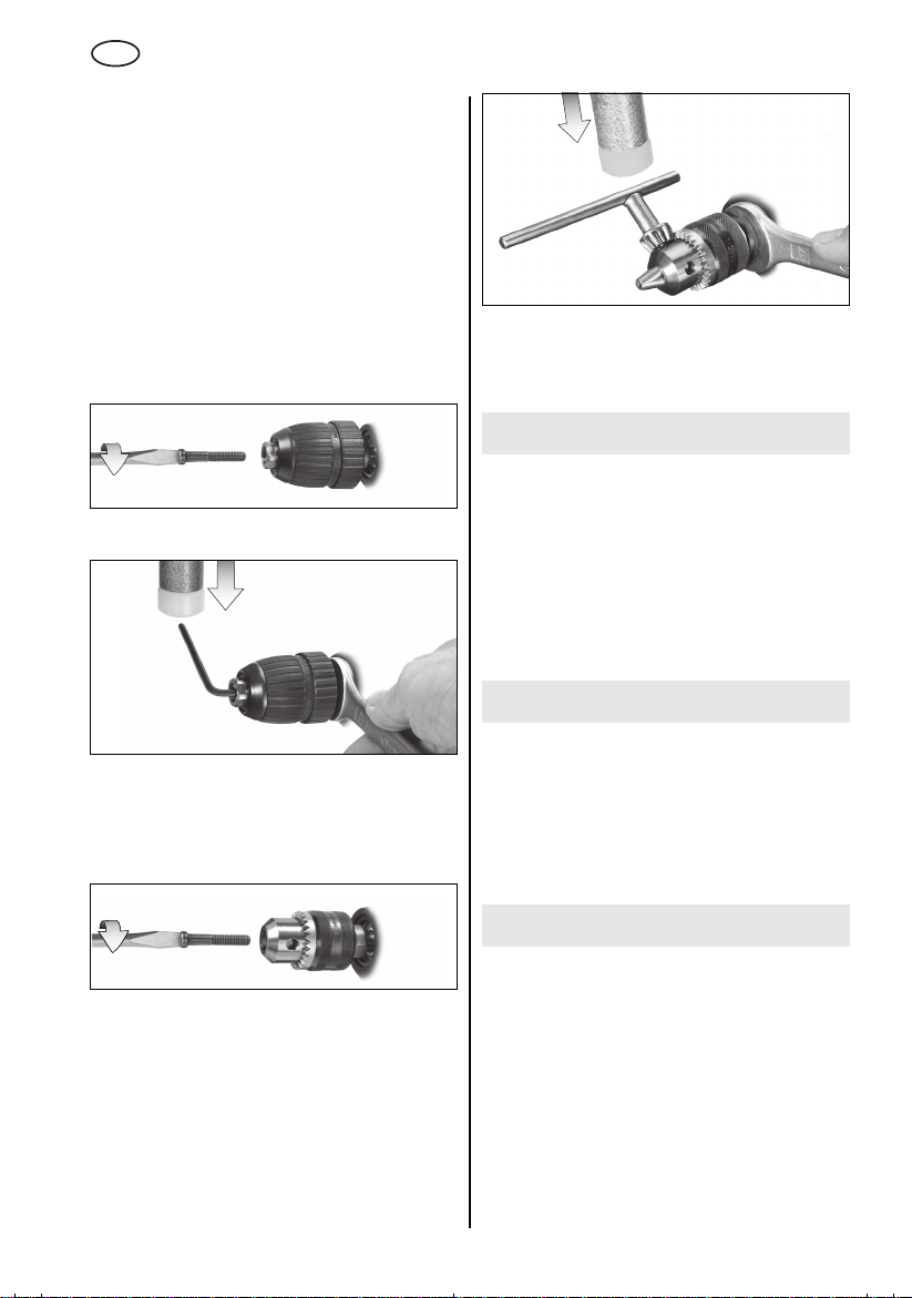
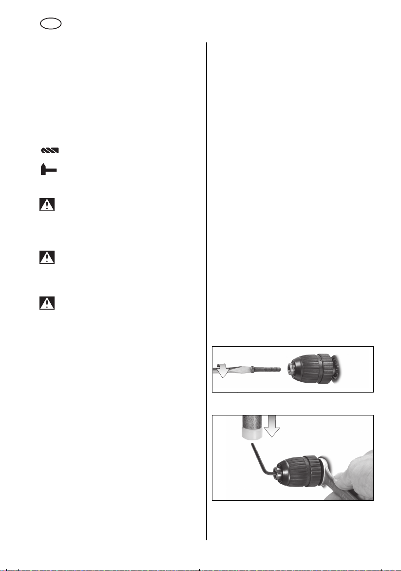
7.6 Werkzeugwechsel
Schnellspann-Bohrfutter Futuro Plus (3)
Maschinen mit der Bezeichnung SB...:
Siehe Abbildungen, Seite 3.
Werkzeug einsetzen. Haltering (a) festhalten und
mit der anderen Hand die Hülse (b) in Richtung
"GRIP, ZU" drehen, bis der spürbare mechanische
Widerstand überwunden ist.
Achtung! Werkzeug ist jetzt noch nicht
gespannt!
muss es "klicken"
möglich ist gespannt.
Bei weichem Werkzeugschaft muss eventuell nach
kurzer Bohrzeit nachgespannt werden.
Bohrfutter öffnen:
Haltering (a) festhalten und mit der anderen Hand
Hülse (b) in Richtung "AUF, RELEASE" drehen.
Hinweis:
eventuell hörbare Ratschen (funktionsbedingt)
wird durch Gegendrehen der Hülse ausgeschaltet.
Bei sehr fest geschlossenem Bohrfutter:
Netzstecker ziehen. Das Bohrfutter mit einem
Gabelschlüssel am Bohrfutterkopf festhalten und
Hülse (b) kräftig in Richtung "AUF, RELEASE"
drehen.
Maschinen mit der Bezeichnung B...:
Siehe Abbildungen, Seite 3.
Werkzeug einsetzen. Haltering (a) festhalten und
mit der anderen Hand die Hülse (b) in Richtung
"GRIP, ZU" drehen, bis kein Weiterdrehen mehr
möglich ist.
Bei weichem Werkzeugschaft muss eventuell nach
kurzer Bohrzeit nachgespannt werden.
Bohrfutter öffnen:
Haltering (a) festhalten und mit der anderen Hand
Hülse (b) in Richtung "AUF, RELEASE" drehen.
Bei sehr fest geschlossenem Bohrfutter:
Netzstecker ziehen. Das Bohrfutter mit einem
Gabelschlüssel am Bohrfutterkopf festhalten und
Hülse (b) kräftig in Richtung "AUF, RELEASE"
drehen.
So lange kräftig weiterdrehen (
), bis kein Weiterdrehen mehr
erst jetzt
Das nach dem Öffnen des Bohrfutters
ist das Werkzeug
7
Page 8
D
DEUTSCH
7.7 Werkzeugwechsel
Zahnkranz-Bohrfutter (2)
Siehe Abbildungen, Seite 3.
Werkzeug einspannen:
Werkzeug einsetzen und mit Bohrfutterschlüssel
(1) gleichmäßig in allen 3 Bohrungen festspannen.
Werkzeug entnehmen:
Zahnkranz-Bohrfutter (2) mit Bohrfutterschlüssel
(1) öffnen und Werkzeug entnehmen.
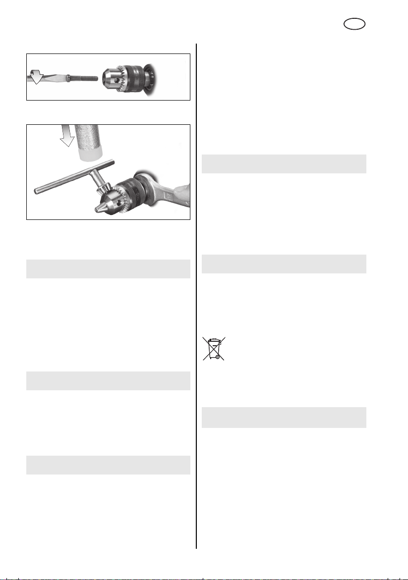
7.8 Bohrfutter abnehmen
Schnellspann-Bohrfutter Futuro Plus
Sicherungsschraube herausdrehen - falls
vorhanden. Achtung Linksgewinde!
Bohrspindel mit einem Gabelschlüssel festhalten.
Bohrfutter durch leichten Schlag mit einem
Gummihammer auf einen eingespannten
Sechskantschlüssel lösen und abschrauben.
Zahnkranzbohrfutter
Bohrspindel mit einem Gabelschlüssel festhalten.
Bohrfutter durch leichten Schlag mit einem
Gummihammer auf den eingesteckten
Bohrfutterschlüssel lösen und abschrauben.
8 Tipps und Tricks
Bei tiefen Bohrungen den Bohrer von Zeit zu Zeit
aus der Bohrung ziehen, um das Bohrmehl oder
Späne zu entfernen.
SBE 561, SBE 550, SBE 521, BE 561: Zum
Schrauben kann das Bohrfutter abgeschraubt
werden. Schrauber-Bit direkt in den
Innensechskant der Spindel einsetzen.
Bei angebrachter Bit-Spannbuchse
Best.-Nr. 6.31281)
gehalten.
wird der Schrauber-Bit
(als Zubehör:
9 Wartung
Schnellspannbohrfutter reinigen:
Nach längerem Gebrauch das Bohrfutter mit der
Öffnung senkrecht nach unten halten und
mehrmals ganz öffnen und schließen. Der
angesammelte Staub fällt aus der Öffnung. Die
regelmäßige Anwendung von Reinigungsspray an
den Spannbacken und Spannbackenöffnungen
wird empfohlen.
f
10 Zubehör
Sicherungsschraube herausdrehen - falls
vorhanden. Achtung Linksgewinde!
8
Verwenden Sie nur original Metabo Zubehör.
Wenn Sie Zubehör benötigen, wenden Sie sich
bitte an Ihren Händler.
Zur Auswahl des richtigen Zubehörs teilen Sie
dem Händler bitte den genauen Typ Ihres
Elektrowerkzeugs mit.
Siehe Seite 4.
A Winkelbohr- und Schraubvorsatz
B Biegewelle
CBohrständer
D Maschinenschraubstock
E Stahldraht-Pinselbürste
Page 9
DEUTSCH
D
F Stahldraht-Topfbürste
G Stahldraht-Rundbürste
H Bit-Spannbuchse
Zubehör-Komplettprogramm siehe
www.metabo.com oder Hauptkatalog.
11 Reparatur
Reparaturen an Elektrowerkzeugen dürfen nur
durch eine Elektrofachkraft ausgeführt werden!
Reparaturbedürftige Metabo Elektrowerkzeuge
können an die auf der Ersatzteilliste angegebenen
Adressen eingesandt werden.
Bitte beschreiben Sie bei der Einsendung zur
Reparatur den festgestellten Fehler.
12 Umweltschutz
Metaboverpackungen sind 100% recyclingfähig.
Ausgediente Elektrowerkzeuge und Zubehör
enthalten große Mengen wertvoller Roh- und
Kunststoffe, die ebenfalls einem Recyclingprozess
zugeführt werden können.
Diese Gebrauchsanleitung ist auf chlorfrei
gebleichtem Papier gedruckt.
Nur für EU-Länder: Werfen Sie
Elektrowerkzeuge nicht in den Hausmüll!
Gemäß Europäischer Richtlinie
2002/96/EG über Elektro- und ElektronikAltgeräte und Umsetzung in nationales Recht
müssen verbrauchte Elektrowerkzeuge getrennt
gesammelt und einer umweltgerechten
Wiederverwertung zugeführt werden.
13 Technische Daten
Erläuterungen zu den Angaben auf Seite 2.
Änderungen im Sinne des technischen Fortschritts
vorbehalten.
= Nennaufnahmeleistung
P
1
P
= Abgabeleistung
2
n
= Leerlaufdrehzahl
0
n
= Drehzahl bei Nennlast
1
ø max = maximaler Bohrdurchmesser
s max = maximale Schlagzahl
G = Bohrspindelgewinde
H = Bohrspindel mit Innensechskant
m = Gewicht ohne Netzkabel
D = Spannhalsdurchmesser
Schwingungsgesamtwert (Vektorsumme dreier
Richtungen) ermittelt entsprechend EN 60745:
a
= Schwingungsemissionswert
h, ID
a
h, D
K
h,ID,Kh,D
(Schlagbohren in Beton)
= Schwingungsemissionswert
(Bohren in Metall)
= Unsicherheit (Schwingung)
Der in diesen Anweisungen angegebene
Schwingungspegel ist entsprechend einem in
EN 60745 genormten Messverfahren gemessen
worden und kann für den Vergleich von
Elektrowerkzeugen miteinander verwendet
werden. Er eignet sich auch für eine vorläufige
Einschätzung der Schwingungsbelastung.
Der angegebene Schwingungspegel repräsentiert
die hauptsächlichen Anwendungen des
Elektrowerkzeugs. Wenn allerdings das
Elektrowerkzeug für andere Anwendungen,
mit abweichenden Einsatzwerkzeugen oder
ungenügender Wartung eingesetzt wird, kann der
Schwingungspegel abweichen. Dies kann die
Schwingungsbelastung über den gesamten
Arbeitszeitraum deutlich erhöhen.
Für eine genaue Abschätzung der
Schwingungsbelastung sollten auch die Zeiten
berücksichtigt werden, in denen das Gerät
abgeschaltet ist oder zwar läuft, aber nicht
tatsächlich im Einsatz ist. Dies kann die
Schwingungsbelastung über den gesamten
Arbeitszeitraum deutlich reduzieren.
Legen Sie zusätzliche Sicherheitsmaßnahmen
zum Schutz des Bedieners vor der Wirkung von
Schwingungen fest wie zum Beispiel: Wartung von
Elektrowerkzeug und Einsatzwerkzeugen,
Warmhalten der Hände, Organisation der
Arbeitsabläufe.
Typische A-bewertete Schallpegel:
L
= Schalldruckpegel
pA
L
= Schallleistungspegel
WA
K
, KWA= Unsicherheit (Schallpegel)
pA
Beim Arbeiten kann der Geräuschpegel 85 dB(A)
überschreiten.
Gehörschutz tragen!
Messwerte ermittelt gemäß EN 60745.
Die angegebenen technischen Daten sind
toleranzbehaftet (entsprechend den jeweils
gültigen Standards).
9
Page 10
ENG
ENGLISH
Operating Instructions
Dear Customer,
Thank you for the trust you have placed in us by buying a Metabo power tool. Each Metabo power tool
is carefully tested and subject to strict quality controls by Metabo's quality assurance. Nevertheless, the
service life of a power tool depends to a great extent on you. Please observe the information contained
in these instructions and the enclosed documentation. The more carefully you treat your Metabo power
tool, the longer it will provide dependable service.
Contents
1 Declaration of Conformity
2 Specified Conditions of Use
3 General Safety Instructions
4 Special Safety Instructions
5Overview
6 Initial Operation
6.1 Attaching the Additional Handle
(SBE 561, SBE 550, SBE 521,
SB 561)
7Use
7.1 Adjusting the Depth Stop (SBE 561,
SBE 550, SBE 521, SB 561)
7.2 Switching On and Off
7.3 Speed Preselection (SBE 561,
SBE 550, SBE 521, BE 561)
7.4 Switching Between Normal Drilling/
Impact Drilling
SBE 521, SB 561)
7.5 Selecting the Direction of Rotation
(SBE 561, SBE 550, SBE 521, BE 561)
7.6 Tool Change With Futuro Plus Keyless
Chuck (3)
7.7 Tool Change With Geared Chuck (2)
7.8 Removing the Chuck
8 Tips and Tricks
9 Maintenance
10 Accessories
11 Repairs
12 Environmental Protection
13 Technical Specifications
(SBE 561, SBE 550,
1 Conformity Declaration
We, being solely responsible, hereby declare that
this product conforms to the standards and directives specified on page 2.
2 Specified Use
SBE 561, SBE 550, SBE 521, SB 561:
The machine is suitable for non-impact drilling in
metal, wood, plastic and similar materials and
impact drilling in concrete, stone and similar materials.
BE 561, B 561:
The machine is suitable for non-impact drilling in
metal, wood, plastic and similar materials.
SBE 561, SBE 550, SBE 521, BE 561:
The machine is suitable for thread cutting and
screwdriving.
The user bears sole responsibility for damage
caused by improper use.
Generally accepted accident prevention regulations and the enclosed safety information must be
observed.
3 General Safety Instructions
WARNING
instructions will reduce the risk
of injury.
WARNING Read all safety warnings and
instructions. Failure to follow all safety
warnings and instructions may result in electric
shock, fire and/or serious injury.
Keep all safety instructions and information for
future reference.
Before using the power tool, carefully read through
and familiarise yourself with all the enclosed safety
information and the Operating Instructions. Keep
all enclosed documentation for future reference,
and pass on your power tool only together with this
documentation.
– Reading the operating
4 Special Safety Instructions
For your own protection and the protection of your power tool, observe the
passages marked by this symbol!
10
Always wear hearing protection when using
hammer drills.
of hearing.
Exposure to noise can cause loss
Page 11
ENGLISH
ENG
Use the additional handle supplied with the
tool.
Loss of control can lead to injuries.
Hold the power tool by insulated gripping
surfaces when performing an operation where
the cutting accessory may contact hidden
wiring or its own cord.
contacting a "live" wire may make exposed
metal parts of the power tool "live" and shock the
operator.
Pull the plug out of the plug socket before any
adjustments or servicing are performed.
Beware of gas/water pipes and electric cables!
Avoid inadvertent starts by always unlocking the
switch when the plug is removed from the mains
socket or in case of a power cut.
Keep hands away from the rotating tool!
Remove chips and similar material only with the
machine at standstill.
Caution must be exercised when driving screws
into hard materials (driving screws with metric or
imperial threads into steel)! The screw head may
break or a high reverse torque may build up.
The machine produces powerful forces when
seizing or catching the workpiece. Always hold the
machine firmly, adopt a steady stance and focus on
your work.
Secure small workpieces. For example, clamp in a
vice.
Dust from material such as paint containing lead,
some wood species, minerals and metal may be
harmful. Contact with or inhalation of the dust may
cause allergic reactions and/or respiratory
diseases to the operator or bystanders.
Certain kinds of dust are classified as carcinogenic
such as oak and beech dust especially in conjunction with additives for wood conditioning (chromate,
wood preservative). Material containing asbestos
must only be treated by specialists.
- Where the use of a dust extraction device is
possible it shall be used.
- The work place must be well ventilated.
- The use of a dust mask of filter class P2 is
recommended.
Follow national requirements for the materials you
want to work with.
Cutting accessory
5Overview
See page 3 (please unfold).
1 Chuck key (for geared chuck) *
2 Geared chuck *
3 Futuro Plus keyless chuck *
4Depth stop *
5
Additional handle *
6 Direction switch *
7 Sliding switch for normal drilling/impact
drilling *
8 Lock button (continuous operation)
9Trigger
10 Speed preselection wheel *
* depending on the features / model
6 Commissioning
Before plugging in, check to see that the
rated mains voltage and mains frequency,
as stated on the rating label, match with your
power supply.
SBE 561, SBE 550, SBE 521, BE 561:
Make sure the chuck clamps securely:
After drilling for the first time (clockwise), firmly
tighten the safety screw inside the chuck using
a screwdriver. Caution: left-handed thread!
(see Section 7.8)
6.1 Attaching the Additional Handle
(SBE 561, SBE 550, SBE 521, SB 561)
For safety reasons, always use the
additional handle supplied.
Open the clamping ring by turning the additional
handle (5) anticlockwise. Push the additional
handle onto the collar of the machine. Insert the
depth stop (4). Securely tighten the additional
handle at the angle required for the application.
7Use
7.1 Adjusting the Depth Stop
(SBE 561, SBE 550, SBE 521, SB 561)
Loosen the additional handle (5). Set depth stop (4)
to the desired drilling depth and retighten additional handle.
7.2 Switching On and Off
To start the machine, press the trigger switch (9).
SBE 561, SBE 550, SBE 521, BE 561: Press in the
trigger switch to change the speed.
For continuous operation the trigger switch can be
locked using the lock button (8). To stop the
machine, press the trigger switch again.
In continuous operation, the machine
continues running if it is forced out of your
hands. Therefore, always hold the machine
with both hands using the handles provided,
stand in a safe position and concentrate.
11
Page 12
ENG
ENGLISH
7.3 Speed Preselection
(SBE 561, SBE 550, SBE 521, BE 561)
Select the (10) maximum speed using the preselection wheel. See page 4 for recommended
drilling speeds.
7.4 Switching Between Normal Drilling/
Impact Drilling
(SBE 561, SBE 550, SBE 521, SB 561)
Select the desired operating mode by pushing the
sliding switch (7).
Drilling
Impact drilling
Work with high speed settings when impact drilling.
Impact drilling and normal drilling only in a
clockwise direction.
7.5 Selecting the Direction of Rotation
(SBE 561, SBE 550, SBE 521, BE 561)
Do not activate the direction switch (6)
unless the motor has completely stopped.
Select direction of rotation:
R=Clockwise
L = Anticlockwise
Screw the chuck firmly to the spindle and
tighten the safety screw inside the chuck
using a screwdriver. (Caution: left-handed
thread!)
Otherwise it may come loose during anticlockwise operation (e.g. when screwdriving).
If the chuck is very securely tightened:
Hold the drill chuck using an open-end spanner at
the flats on its head, and turn the sleeve (b) vigourously in the direction of "AUF, RELEASE".
Machines with the designation B...:
See illustrations on page 3.
Insert the tool. Hold the retaining ring (a) firmly and
turn the collet (b) towards "GRIP, ZU" with the other
hand until it will not turn any further.
With a soft tool shank, retightening may be required
after a short drilling period.
Open the chuck:
Hold the retaining ring (a) firmly and turn the collet
(b) towards "AUF, RELEASE" with the other hand.
If the chuck is very securely tightened:
Hold the drill chuck using an open-end spanner at
the flats on its head, and turn the sleeve (b) vigourously in the direction of "AUF, RELEASE".
7.7 Tool Change With
Geared Chuck (2)
See illustrations on page 3.
Clamping tools:
Insert the tool and clamp evenly in all 3 holes using
the chuck key (1).
Removing tools:
Open the geared chuck (2) using the chuck key (1)
and remove the tool.
7.8 Removing the Chuck
Futuro Plus keyless chuck
Unplug.
Unplug.
7.6 Tool Change With
Futuro Plus Keyless Chuck (3)
Machines with the designation SB...:
See illustrations on page 3.
Insert the tool. Hold the retaining ring (a) firmly and
turn the collet (b) towards "GRIP, ZU" with the other
hand until the mechanical resistance which can be
felt is overcome.
Caution! The tool is not yet clamped!
turning the sleeve (
until it cannot be turned any further the tool
securely
With a soft tool shank, retightening may be required
after a short drilling period.
Open the chuck:
Hold the retaining ring (a) firmly and turn the collet
(b) towards "AUF, RELEASE" with the other hand.
Note:
The grating sound which may be heard after
opening the drill chuck is functional and is stopped
by turning the sleeve in the opposite direction.
it must "click" when turning
clamped.
Keep
only now
is
12
Unscrew the safety screw - if available. Caution:
left-handed thread!
)
Hold the drill spindle securely using an open-end
wrench. Clamp an Allen key in the chuck and strike
lightly with a rubber hammer to loosen, then
unscrew.
Page 13
ENGLISH
ENG
Geared chuck
Unscrew the safety screw - if available. Caution:
left-handed thread!
Hold the drill spindle securely using an open-end
wrench. Insert the key in the chuck and strike lightly
with a rubber hammer to loosen, then unscrew.
8 Tips and Tricks
In the case of deep bores, pull the drill bit out of the
bore from time to time in order to remove the drill
dust or swarf.
SBE 561, SBE 550, SBE 521, BE 561: The chuck
can be removed to insert a screwdriver bit. Insert
the bit directly in the hexagon socket on the
spindle.
The screwdriver bit is retained if a bit clamping
bush
(as an accessory: order no. 6.31281)
is fitted.
9 Maintenance
Keyless chuck cleaning:
After prolonged use hold the chuck vertically, with
the opening facing down, and fully open and close
it several times. The dust collected falls from the
opening. Regular use of cleaning spray on the jaws
and jaw openings is recommended.
f
10 Accessories
Use only genuine Metabo accessories.
If you need any accessories, check with your
dealer.
For dealers to select the correct accessory, they
need to know the exact model designation of your
power tool.
See page 4.
A Angle attachment
B Flexible drive shaft
C Drill stand
D Machine vice
E Steel wire end brush
F Steel wire cup brush
G Steel wire wheel
H Bit clamping bush
For complete range of accessories, see
www.metabo.com or the main catalogue.
11 Repairs
Repairs to electrical tools must be carried out by
qualified electricians ONLY!
Any Metabo power tool in need of repair can be
sent to one of the addresses listed in the spare
parts list.
Please enclose a description of the fault with the
power tool.
12 Environmental Protection
Metabo's packaging can be 100% recycled.
Scrap power tools and accessories contain large
amounts of valuable resources and plastics that
can be recycled.
These instructions are printed on chlorine-free
bleached paper.
Only for EU countries: Never dispose of
power tools in your household waste! In
accordance with European Guideline
2002/96/EC on used electronic and
electric equipment and its implementation in
national legal systems, used power tools must be
collected separately and handed in for
environmentally compatible recycling.
13 Technical Specifications
Explanatory notes on the specifications on page 2.
Changes due to technological progress reserved.
P
= Nominal power input
1
P2 = Power output
n
= No load speed
0
n
= Speed at rated load
1
ø max = Max. solid drill diameter
s max = Max. impact rate
G = Drill spindle thread
H = Drill spindle with hexagon socket
m = Weight without mains cable
D = Collar diameter
13
Page 14
ENG
ENGLISH
Vibration total value (vector sum of three
directions) determined in accordance with
EN 60745:
a
= Vibration emission value
h, ID
a
h, D
K
h,ID,Kh,D
The vibration emission level given in this information sheet has been measured in accordance with
a standardised test given in EN 60745 and may be
used to compare one tool with another. It may be
used for a preliminary assessment of exposure.
(impact drilling into concrete)
= Vibration emission value
(drilling into metal)
= Unsafe (vibration)
The declared vibration emission level represents
the main applications of the tool. However if the tool
is used for different applications, with different
accessories or poorly maintained, the vibration
emission may differ. This may significantly increase
the exposure level over the total working period.
An estimation of the level of exposure to vibration
should also take into account the times when the
tool is switched off or when it is running but not
actually doing the job. This may significantly reduce
the exposure level over the total working period.
Identify additional safety measures to protect the
operator from the effects of vibration such as:
maintain the tool and the accessories, keep the
hands warm, organisation of work patterns.
Typical A-effective perceived sound levels:
L
= Sound pressure level
pA
L
= Acoustic power level
WA
K
, KWA= Unsafe (noise level)
pA
During operation the noise level can exceed
85 dB(A).
Wear ear protectors!
Measured values determined in conformity with
EN 60745.
The technical specifications quoted are subject to
tolerances (in compliance with the relevant valid
standards).
14
Page 15
FRANÇAIS
F
Mode d'emploi
Cher client,
merci de la confiance que vous nous avez témoignée en achetant un outil électrique Metabo. Tous les
outils électriques Metabo sont testés avec soin et font l'objet de contrôles qualité très stricts effectués
par le Service Qualité Metabo. Mais c'est vous qui avez la plus grande influence sur la durée de vie de
votre outil électrique. Veuillez respecter les informations contenues dans ces instructions d'utilisation et
dans les documents ci-joints. En prenant grand soin de votre outil électrique Metabo, vous en augmenterez la durée de vie et en garantirez le bon fonctionnement.
Sommaire
1 Déclaration de conformité
2 Utilisation conforme à la destination
3 Consignes générales de sécurité
4 Consignes de sécurité particulières
5Vue d'ensemble
6 Mise en service
6.1 Montage de la poignée supplémentaire (SBE 561, SBE 550, SBE 521,
SB 561)
7 Utilisation
7.1 Réglage de la butée de profondeur de
perçage (SBE 561, SBE 550,
SBE 521, SB 561)
7.2 Marche/arrêt
7.3 Présélection de la vitesse (SBE 561,
SBE 550, SBE 521, BE 561)
7.4
Sélection perçage avec/sans percussion
(SBE 561, SBE 550, SBE 521, SB 561)
7.5 Sélection du sens de rotation
(SBE 561, SBE 550, SBE 521, BE 561)
7.6 Changement d'accessoire avec le
mandrin autoserrant Futuro Plus (3)
7.7 Changement d'accessoire avec le
mandrin à clé (2)
7.8 Dépose du mandrin
8 Conseils et astuces
9 Maintenance
10 Accessoires
11 Réparations
12 Protection de l'environnement
13 Caractéristiques techniques
1 Déclaration de conformité
Nous déclarons sous notre propre responsabilité
que ce produit est conforme aux normes et directives indiquées page 2.
2 Utilisation conforme à la
destination
SBE 561, SBE 550, SBE 521, SB 561 :
Cette machine convient pour le perçage sans
percussion sur métal, bois, matières plastiques et
assimilées, ainsi que pour le perçage avec percussion sur béton, pierre et matériaux similaires.
BE 561, B 561 :
Cette machine convient pour le perçage sans
percussion sur métal, bois, matières plastiques et
assimilées.
SBE 561, SBE 550, SBE 521, BE 561 :
Cette machine convient pour les travaux de taraudage et de vissage.
L'utilisateur sera entièrement responsable de tous
dommages résultant d'une utilisation non
conforme à la destination de la machine.
Il est impératif de respecter les consignes
générales de protection contre les accidents ainsi
que les consignes de sécurité ci-jointes.
3 Consignes générales de
sécurité
AVERTISSEMENT
d'utilisation afin d'éviter tout risque de
blessure.
AVERTISSEMENT Lire toutes les
consignes de sécurité et instructions.
Le non-respect des consignes de sécurité et des
instructions peut être à l'origine d'un choc
électrique, d'un incendie et/ou de blessures
graves.
Conserver toutes les consignes de sécurité et
instructions.
Avant d'utiliser l'outil électrique, lire attentivement
et entièrement les instructions de sécurité ainsi
que le mode d'emploi ci-joints. Conserver les
documents ci-joints et veiller à les remettre
obligatoirement avec l'appareil à tout utilisateur
concerné.
– Lire la notice
15
Page 16

F
FRANÇAIS
4 Consignes de sécurité
particulières
Dans l'intérêt de votre propre sécurité et
afin de protéger votre outil électrique,
respectez les passages de texte
marqués de ce symbole !
Porter une protection auditive lors de l'utilisation d'une perceuse à percussion.
susceptible de provoquer une perte de capacité
auditive.
Utiliser la poignée complémentaire fournie
avec l'outil.
risque de blessures.
Lors d'opérations où l'accessoire risque de
rencontrer des conducteurs électriques non
apparents, voire son câble d'alimentation, tenir
l'outil exclusivement par les côtés isolés des
poignées.
trique sous tension peut également mettre les
parties métalliques de l'outil sous tension et provoquer un choc électrique.
Débrancher le cordon d'alimentation de la prise de
courant avant toute opération de réglage ou de
maintenance.
Veillez à ne toucher aucune conduite de gaz, électricité ou eau !
Eviter les démarrages intempestifs : la gâchette
doit toujours être déverrouillée lorsque l'on retire le
connecteur de la prise ou après une coupure de
courant.
Ne pas toucher l'outil lorsque la machine est en
marche !
Eliminer sciures de bois et autres uniquement
lorsque la machine est à l'arrêt.
Attention pour les vissages en force (avec des vis
à pas métrique ou en pouces sur de l'acier) !
Risque d'arrachement de la tête de vis ou d'apparition de couples de réaction élevés.
Si l'outil inséré dans le mandrin reste coincé ou
accroché, des forces importantes apparaîtront.
Maintenez donc toujours fermement la machine,
positionnez-vous dans une posture stable et
restez concentré en travaillant.
Fixer les pièces de petite taille, par ex. en les
serrant dans un étau.
Les poussières de matériaux tels que les peintures
au plomb, certains types de bois, de minéraux et de
métaux peuvent s'avérer nocives pour la santé.
Toucher ou inhaler ces poussières peut entraîner
des réactions allergiques et/ou des maladies
respiratoires chez l'utilisateur ou les personnes
se trouvant à proximité.
Certaines poussières provenant par exemple du
chêne ou du hêtre sont considérées comme
cancérigènes, particulièrement lorsqu'elle sont
En cas de perte de contrôle, il y a un
Le contact avec un conducteur élec-
16
Le bruit est
associées à des adjuvants de traitement du bois
(chromate, produit de protection du bois). Seuls
des spécialistes sont habilités à traiter les
matériaux contenant de l'amiante.
- Utiliser le plus possible un système d'aspiration
des poussières.
- Veiller à une bonne aération du site de travail.
- Il est recommandé de porter un masque antipoussières avec filtre à particules de classe 2.
Respecter les directives nationales en vigueur
relatives aux matériaux à traiter.
5Vue d'ensemble
Voir page 3 (à déplier).
1 Clé de mandrin (pour mandrins à clé) *
2 Mandrin à couronne dentée *
3 Mandrin autoserrant Futuro Plus *
4 Butée de profondeur de perçage *
5
Poignée supplémentaire *
6 Commutateur du sens de rotation *
7 Interrupteur coulissant perçage avec/sans
percussion *
8 Bouton de blocage (marche continue)
9 Gâchette
10 Molette de présélection de la vitesse *
* en fonction de l'équipement / du modèle choisis
6 Mise en service
Avant la mise en service, comparez si
tension secteur et la fréquence secteur
indiquées sur la plaque signalétique correspondent aux caractéristiques de votre réseau de
courant.
SBE 561, SBE 550, SBE 521, BE 561 :
Afin de garantir la bonne tenue en place
du mandrin :
(en rotation à droite), resserrer vigoureusement la
vis de freinage à l'intérieur du mandrin à l'aide d'un
tournevis. Attention, il s'agit d'un pas à gauche !
(voir chapitre 7.8)
6.1 Montage de la poignée supplémentaire
est comprise dans la livraison.
Ouvrir l'anneau de serrage en tournant la poignée
(5) vers la gauche. Faire coulisser la poignée sur le
collier de la machine. Introduire la butée de profondeur (4). Selon l'utilisation souhaitée, serrer la
poignée dans l'angle désiré.
dès la fin du premier perçage
(SBE 561, SBE 550, SBE 521, SB 561)
Pour des raisons de sécurité, utilisez
toujours la poignée supplémentaire qui
Page 17

FRANÇAIS
F
7 Utilisation
7.1 Réglage de la butée de profondeur de
perçage
(SBE 561, SBE 550, SBE 521, SB 561)
Desserrer la poignée supplémentaire (5). Régler la
butée de profondeur (4) à la profondeur de
perçage voulue et resserrer la poignée supplémentaire.
7.2 Marche/arrêt
Pour mettre l'outil en route, appuyer sur la
gâchette (9).
SBE 561, SBE 550, SBE 521, BE 561 : La vitesse
peut être modifiée en pressant la gâchette.
Pour un fonctionnement en continu, il est possible
de bloquer la gâchette à l'aide du bouton de
blocage (8). Pour arrêter la machine, appuyer
à nouveau sur la gâchette.
Lorsque l'outil est en position de marche
continue, il continue de tourner s'il vous
échappe des mains. Afin d'éviter tout comportement inattendu de l'outil, le tenir avec les
deux mains au niveau des poignées, veiller
à un bon équilibre et travailler de manière
concentrée.
7.3 Présélection de la vitesse
(SBE 561, SBE 550, SBE 521, BE 561)
Présélectionner la vitesse maximale sur la molette
(10). Voir les vitesses de perçage recommandées
page 4.
7.4 Sélection perçage avec/
sans percussion
(SBE 561, SBE 550, SBE 521, SB 561)
Le mode de fonctionnement voulu est sélectionné
en déplaçant l'interrupteur coulissant (7).
Perçage sans percussion
Perçage avec percussion
Pour le perçage avec percussion, utiliser une
vitesse élevée.
Pour tous perçages avec ou sans percus-
sion, la rotation à droite est obligatoire.
7.5 Sélection du sens de rotation
(SBE 561, SBE 550, SBE 521, BE 561)
S'assurer que le moteur est à l'arrêt avant
d'actionner le commutateur du sens de
rotation (6).
Sélectionner le sens de rotation:
R = Rotation à droite
L = Rotation à gauche
Le mandrin doit être fermement vissé sur
la broche et la vis de freinage à l'intérieur
du mandrin doit être vigoureusement serrée à
l'aide d'un tournevis. (Attention, il s'agit d'un
pas à gauche !)
En effet, il risquerait de se desserrer dans
le cas contraire lors d'une rotation à gauche
(par ex. au vissage).
7.6 Changement d'accessoire
Mandrin autoserrant Futuro Plus (3)
Machines avec une désignation en SB... :
Voir les illustrations page 3.
Insérer l'outil. Maintenir l'anneau de maintien (a) et
de l'autre main, tourner la douille (b) dans le sens
indiqué "GRIP, ZU" jusqu'à ce que la résistance
mécanique perceptible soit dépassée.
Attention ! L'outil n'est alors pas encore serré !
Continuer à tourner avec force
un "clic")
tourner du tout l'outil est
En cas d'outils souples, il faudra éventuellement
resserrer peu de temps après le début du travail
de perçage.
Pour ouvrir le mandrin :
Maintenir l'anneau de maintien (a) et de l'autre
main, tourner la douille (b) dans le sens marqué
"AUF, RELEASE".
Remarque :
éventuellement après avoir ouvert le mandrin de
perçage (bruit dû au fonctionnement) disparaîtra
si l'on tourne la douille dans le sens contraire.
Au cas où le mandrin est complètement bloqué
:
Débrancher le cordon d'alimentation. Maintenir le
mandrin au niveau de la tête avec une clé à fourche
et tourner la douille (b) avec force dans le sens
marqué "AUF, RELEASE".
Machines avec une désignation en B... :
Voir les illustrations page 3.
Insérer l'outil. Maintenir l'anneau de maintien (a) et
de l'autre main, tourner la douille (b) dans le sens
indiqué "GRIP, ZU" jusqu'à ce qu'il devienne
impossible de la tourner plus loin.
En cas d'outils souples, il faudra éventuellement
resserrer peu de temps après le début du travail de
perçage.
jusqu'à ce que l'on ne puisse plus
ce n'est que maintenant
véritablement
Le cliquètement que l'on entend
(on doit entendre
serré.
que
17
Page 18

F
FRANÇAIS
Pour ouvrir le mandrin :
Maintenir l'anneau de maintien (a) et de l'autre
main, tourner la douille (b) dans le sens marqué
"AUF, RELEASE".
Au cas où le mandrin est complètement bloqué
:
Débrancher le cordon d'alimentation. Maintenir le
mandrin au niveau de la tête avec une clé à fourche
et tourner la douille (b) avec force dans le sens
marqué "AUF, RELEASE".
7.7 Changement d'accessoire
Mandrin à clé (2)
Voir les illustrations page 3.
Pour insérer l'outil :
Insérer l'outil et le serrer à l'aide d'une clé de
mandrin (1) en veillant à bien répartir l'effort sur les
3 perçages.
Pour sortir l'outil :
Ouvrir le mandrin à clé (2) à l'aide de la clé de
mandrin (1) et sortir l'outil.
7.8 Dépose du mandrin
Mandrin autoserrant Futuro Plus
Dévisser la vis de freinage (s'il y en a une). Attention, il s'agit d'un pas à gauche !
Dévisser la vis de freinage (s'il y en a une).
Attention, il s'agit d'un pas à gauche !
Maintenir la broche à l'aide d'une clé à fourche.
Décoller le mandrin en tapotant légèrement avec
un maillet en plastique sur la clé de mandrin
insérée dans le mandrin, puis dévisser.
8 Conseils et astuces
En cas de perçages profonds, il faut retirer de
temps en temps le foret du trou pour éliminer les
poussières de perçage ou les copeaux.
SBE 561, SBE 550, SBE 521, BE 561 : Le mandrin
peut être dévissé pour les travaux de vissage. On
insère alors l'embout de vissage directement dans
le six pans creux de la broche.
Si une douille de serrage d'embouts
comme accessoire : réf. de cde 6.31281)
installée, l'embout de vissage sera maintenu en
place.
(disponible
a été
9 Maintenance
Maintenir la broche à l'aide d'une clé à fourche.
Décoller le mandrin en tapotant légèrement avec
un maillet en plastique sur une clé six pans insérée
dans le mandrin, puis dévisser.
Mandrin à clé
18
Nettoyage du mandrin autoserrant :
Après une utilisation prolongée du mandrin, tenir
celui-ci en position verticale, ouverture vers le bas,
l'ouvrir entièrement et le refermer, puis recommencer plusieurs fois de suite. La poussière qui
s'était accumulée tombera alors par l'ouverture. Il
est conseillé d'utiliser régulièrement un spray de
nettoyage pour les mâchoires de serrage.
f
10 Accessoires
Utilisez uniquement du matériel Metabo.
S'il vous faut des accessoires, veuillez vous
adresser à votre revendeur.
Pour pouvoir sélectionner les accessoires appro-
priés, veuillez indiquer le type exact de votre outil
électrique au distributeur.
Page 19

FRANÇAIS
F
Voir page 4.
A Adaptation renvoi d'angle
B Flexible
C Support de perçage
DÉtau
E Brosse métallique forme pinceau
F Brosse boisseau
G Brosse métallique circulaire
H Douille de serrage pour embouts
Voir programme complet des accessoires sur
www.metabo.com ou dans le catalogue principal.
11 Réparations
Les travaux de réparation sur les outils électriques
ne peuvent être effectués que par un spécialiste !
Les outils Metabo qui sont à réparer peuvent être
expédiés à l'une des adresses indiquées sur la liste
des pièces de rechange.
Prière de joindre à l'outil expédié une description
du défaut constaté.
12 Protection de
l'environnement
Les emballages Metabo sont recyclables à 100 %.
Les outils et accessoires électriques qui ne sont
plus utilisés contiennent de grandes quantités de
matières premières et de matières plastiques de
grande qualité pouvant être également recyclées.
Ce mode d'emploi est imprimé sur du papier
blanchi sans chlore.
Pour les pays européens uniquement : Ne
pas jeter les appareils électriques dans les
ordures ménagères ! Conformément à la
directive européenne 2002/96/CE relative
aux déchets d'équipements électriques ou
électroniques (DEEE), et à sa transposition dans la
législation nationale, les appareils électriques
doivent être collectés à part et être soumis à un
recyclage respectueux de l’environnement.
13 Caractéristiques
techniques
Commentaires sur les indications de la page 2.
Sous réserve de modifications allant dans le sens
du progrès technique.
= Puissance absorbée
P
1
P
= Puissance débitée
2
n
= Vitesse à vide
0
n
= Vitesse en charge nominale
1
= Capacité de perçage maxi
ø
max
s
= Cadence de frappe maxi
max
G = Filet de la broche de perçage
H = Broche de perçage à six pans creux
m = Poids sans cordon d'alimentation
D = Diamètre du collet
Valeur totale d'oscillation (somme des vecteurs
des trois directions) donnée selon la norme
EN 60745:
a
= Valeur d’émission de vibration
h, ID
a
h, D
K
h,ID,Kh,D
Le niveau d'oscillation indiqué dans les présentes
instructions est mesuré selon un procédé conforme
à la norme EN 60745 et peut servir à comparer les
différents outils électriques. Il est également
approprié pour réaliser une estimation provisoire
de l'amplitude d'oscillation.
Le niveau d'oscillation indiqué correspond aux
applications principales de l'outil électrique. Par
ailleurs, le niveau d'oscillation peut dévier si l'outil
électrique est utilisé dans d'autres applications,
avec des outils de travail différents ou avec une
maintenance insuffisante. Cela peut entraîner une
augmentation sensible de l'amplitude d'oscillation
sur la durée totale de travail.
Pour estimer de manière exacte l'amplitude
d'oscillation, il faut également tenir compte des
temps d'arrêt ou de marche à vide de l'outil.
Cela peut entraîner une réduction sensible de
l'amplitude d'oscillation sur la durée totale de
travail.
Définir les mesures de sécurité supplémentaires
relatives à la protection de l'utilisateur contre les
effets des oscillations, telles que : maintenance de
l'outil électrique et outils de travail, maintien des
mains au chaud, organisation du travail.
Niveaux sonores types évalués
L
pA
L
WA
K
, KWA= Incertitude (niveaux sonorex)
pA
Pendant le fonctionnement, il se peut que le niveau
sonore dépasse les 85 db(A).
Valeurs de mesure calculées selon EN 60745.
Les caractéristiques indiquées sont soumises
à tolérance (selon les normes en vigueur
correspondantes).
(perçage avec percussion dans
le béton)
= Valeur d’émission de vibration
(perçage dans le métal)
= Incertitude (oscillation)Niveaux
sonores types évalués
= Niveau de pression acoustique
= Niveau de puissance sonore
Porter un casque antibruit !
19
Page 20

NL
NEDERLANDS
Gebruiksaanwijzing
Geachte klant,
Hartelijk dank voor het vertrouwen dat u ons heeft geschonken bij de aankoop van uw nieuw elektrisch
gereedschap van Metabo. Elektrisch gereedschap van Metabo wordt zorgvuldig getest en moet beantwoorden aan de strenge kwaliteitsnormen en controles van Metabo. De levensduur van elektrisch gereedschap hangt echter in hoge mate van u af. Wij verzoeken u aandacht te schenken aan de informatie in
deze gebruiksaanwijzing en de bijgevoegde documenten. Hoe zorgvuldiger u het elektrisch gereedschap
van Metabo behandelt, des te langer zal het betrouwbaar blijven functioneren.
Inhoud
1 Conformiteitsverklaring
2 Gebruik volgens de voorschriften
3 Algemene veiligheidsvoorschriften
4 Speciale veiligheidsvoorschriften
5Overzicht
6 Inbedrijfstelling
6.1 Montage van de extra handgreep
(SBE 561, SBE 550, SBE 521,
SB 561)
7Gebruik
7.1 Instellen van de boordiepteaanslag
(SBE 561, SBE 550, SBE 521,
SB 561)
7.2 In-/uitschakelen
7.3 Toerental vooraf instellen (SBE 561,
SBE 550, SBE 521, BE 561)
7.4
Omschakelen boren/slagboren
(SBE 561, SBE 550, SBE 521, SB 561)
7.5 Draairichting kiezen (SBE 561, SBE
550, SBE 521, BE 561)
7.6 Gereedschapwissel snelspan-boorhouder Futuro Plus (3)
7.7 Gereedschapwissel tandkrans-boorhouder (2)
7.8 Boorhouder afnemen
8 Handige tips
9 Onderhoud
10 Toebehoren
11 Reparatie
12 Milieubescherming
13 Technische gegevens
1 Conformiteitsverklaring
Wij verklaren op eigen en uitsluitende verantwoording, dat dit product voldoet aan de op pagina 2
genoemde normen en richtlijnen.
2 Gebruik volgens de
voorschriften
SBE 561, SBE 550, SBE 521, SB 561:
De machine is geschikt voor het boren zonder slag
in metaal, hout, kunststof en gelijksoortig materiaal, en voor het slagboren in beton, steen en
dergelijke.
BE 561, B 561:
De machine is geschikt voor het boren zonder slag
in metaal, hout, kunststof en gelijksoortig materiaal.
SBE 561, SBE 550, SBE 521, BE 561:
De machine is geschikt om te schroeven en
schroefdraad te tappen.
Voor schade door oneigenlijk gebruik is alleen de
gebruiker aansprakelijk.
De algemeen erkende veiligheidsvoorschriften en
de bijgevoegde veiligheidsinstructies dienen te
worden nageleefd.
3 Algemene
veiligheidsvoorschriften
WAARSCHUWING
vermindering van het risico van letsel
de handleiding.
WAARSCHUWING Lees alle veiligheidsvoorschriften en aanwijzingen. Worden de
veiligheidsvoorschriften en aanwijzingen niet in
acht genomen, dan kan dit een elektrische schok,
brand en/of ernstig letsel tot gevolg hebben.
Bewaar alle veiligheidsvoorschriften en
aanwijzingen goed met het oog op toekomstig
gebruik.
Lees vóór het in gebruik nemen de bij de machine
behorende veiligheidsinstructies en de gebruiksaanwijzing aandachtig en volledig door. Bewaar
zorgvuldig alle documenten die bij de machine
horen en geef de machine alleen samen met deze
documenten door.
– Lees ter
20
Page 21

4 Speciale
veiligheidsvoorschriften
Let voor uw veiligheid en die van de
machine op de met dit symbool
aangegeven passages!
Draag oorbeschermers bij het gebruik van
slagboormachines.
gehoorverlies.
Gebruik de extra handgreep die bij de levering
van het apparaat inbegrepen is.
controle kan tot letsel leiden.
Houd het apparaat alleen vast aan de geïsoleerde greepvlakken wanneer u werkzaamheden
uitvoert waarbij het inzetgereedschap
verborgen stroomleidingen of het eigen netsnoer kan raken.
spanningvoerende geleider kunnen ook metalen
apparaatonderdelen onder spanning worden
gezet met een elektrische schok als mogelijk
gevolg.
Stekker uit het stopcontact trekken, voordat
enige instelling of onderhoudswerkzaamheden
uitgevoerd worden.
Let op gas-, stroom- en waterleidingen!
Voorkom dat de machine onbedoeld wordt
gestart: schakel de machine altijd uit wanneer de
stekker uit het stopcontact wordt getrokken of
wanneer er een stroomonderbreking optreedt.
Neem de draaiende onderdelen van de machine
niet vast!
Verwijder spanen en dergelijke uitsluitend bij
uitgeschakelde en stilstaande machine.
Let op bij schroeven in hard materiaal (het
inschroeven van schroeven met metrisch of inch
schroefdraad in staal)! De schroefkop kan
afbreken of er kunnen hoge terugdraaimomenten
optreden.
Blijft het gereedschap klemmen of haken, dan
ontstaan er grote krachten. De machine altijd goed
vasthouden, een veilige houding aannemen en
geconcentreerd werken.
Kleine werkstukken bevestigen. Bijv. in een
bankschroef spannen.
Stoffen afkomstig van bepaalde materialen, zoals
loodhoudende verf, enkele houtsoorten, mineralen
en metaal, kunnen schadelijk zijn voor de gezondheid. Het aanraken of inademen van deze stoffen
kan bij de gebruiker of personen die zich in de
nabijheid bevinden leiden tot allergische reacties
en/of aandoeningen aan de luchtwegen.
Bepaalde stoffen, zoals van eiken of beuken,
gelden als kankerverwekkend, met name in verbinding met additieven voor de houtbehandeling
(chromaat, houtbeschermingsmiddelen).
Lawaai kan leiden tot
Verlies van
Door het contact met een
NEDERLANDS
Asbesthoudend materiaal mag alleen worden
bewerkt door vaklui.
- Maak zo mogelijk gebruik van stofafzuiging.
- Zorg voor een goede ventilatie van de
werkplaats.
- Het wordt aanbevolen om een stofmasker met
filterklasse P2 te dragen.
Neem de voorschriften in acht die in uw land voor
de te bewerken materialen van toepassing zijn.
NL
5Overzicht
Zie pagina 3 (uitklappen a.u.b.).
1 Boorhoudersleutel
(voor tandkrans-boorhouder) *
2 Tandkrans-boorhouder *
3 Snelspan-boorhouder Futuro Plus *
4 Boordiepteaanslag *
5
Extra handgreep *
6 Draairichtingschakelaar *
7 Schakelschuiver boren/slagboren *
8 Vergrendelknop (continue inschakeling)
9 Drukschakelaar
10 Stelknop voor de voorinstelling toerental *
* afhankelijk van de uitvoering / het model
6 Inbedrijfstelling
Controleer voordat de machine in gebruik
wordt genomen of de op het typeplaatje
aangegeven spanning overeenkomt met de
netspanning.
SBE 561, SBE 550, SBE 521, BE 561:
Om een goede bevestiging van de boorhouder te garanderen:
(rechtsloop) de borgschroef in de boorhouder
stevig vastzetten met een schroevendraaier. Let
op: Linkse schroefdraad! (Zie hoofdstuk 7.8)
6.1 Montage van de extra handgreep
(SBE 561, SBE 550, SBE 521, SB 561)
Om veiligheidsredenen altijd de meeg-
eleverde extra handgreep gebruiken.
Klemring openen door de extra handgreep (5) naar
links te draaien. De extra handgreep op de spanhals van de machine schuiven. Boordiepteaanslag
(4) inschuiven. De extra handgreep afhankelijk van
de toepassing krachtig in de gewenste hoek
vastdraaien.
Na de eerste keer boren
21
Page 22

NL
NEDERLANDS
7Gebruik
7.1 Instellen van de boordiepteaanslag
(SBE 561, SBE 550, SBE 521, SB 561)
Extra handgreep (5) losdraaien. Stel de boordiepteaanslag (4) in op de gewenste boordiepte en
draai de extra handgreep weer vast.
7.2 In-/uitschakelen
Druk de drukschakelaar (9) in, alvorens de
machine in te schakelen.
SBE 561, SBE 550, SBE 521, BE 561: Het
toerental kan met de drukschakelaar worden
veranderd.
Bij continu gebruik kan de drukschakelaar met de
vastzetknop (8) vastgezet worden. Voor het
uitschakelen de drukschakelaar opnieuw
indrukken.
Bij continue inschakeling loopt de
machine verder wanneer hij uit de hand
wordt getrokken. Daarom de machine altijd
met beide handen aan de hiervoor bestemde
handgrepen vasthouden, ervoor zorgen dat u
stevig staat en geconcentreerd werken.
7.3 Toerental vooraf instellen
(SBE 561, SBE 550, SBE 521, BE 561)
Bij de stelknop (10) het maximale toerental vooraf
instellen. Aanbevolen toerentallen voor het boren,
zie pag. 4.
7.4 Omschakelen boren/slagboren
(SBE 561, SBE 550, SBE 521, SB 561)
De gewenste functie selecteren door de schakelschuiver (7) te verschuiven.
Boren
Slagboren
Bij het slagboren met een hoog toerental werken.
Slagboren en boren alleen bij rechtsloop.
7.5 Draairichting kiezen
(SBE 561, SBE 550, SBE 521, BE 561)
Draairichtingschakelaar (6) alleen
gebruiken wanneer de motor stilstaat.
De boorhouder moet stevig op de spil
geschroefd zijn en de borgschroef in
de boorhouder dient goed met een schroevendraaier te zijn vastgezet. (Let op, linkse
schroefdraad!)
Anders zou hij in linksloop (bijv. bij het
schroeven) los kunnen raken.
7.6 Gereedschapwissel
Snelspan-boorhouder Futuro Plus (3)
Machines met de aanduiding SB...:
Zie afbeeldingen, pag. 3.
Gereedschap inbrengen. Borgring (a) vasthouden
en met de andere hand de huls (b) in de richting
"GRIP, ZU" draaien totdat er geen merkbare
mechanische weerstand meer is.
Let op! Gereedschap is nu nog niet gespannen!
Met kracht verder draaien (
hoorbaar zijn
mogelijk is gespannen.
Bij een zachte gereedschapschacht moet eventueel na een korte boortijd worden nagespannen.
Boorhouder openen:
Borgring (a) vasthouden en met de andere hand de
huls (b) in de richting "AUF, RELEASE" draaien.
Aanwijzing:
boorhouder eventueel hoorbaar is (afhankelijk van
de functie) wordt uitgeschakeld door de huls in de
tegengestelde richting te draaien.
Bij een zeer vast gesloten boorhouder:
stekker uit het stopcontact halen. De boorhouder
met een steeksleutel aan de boorhouderkop vasthouden en de huls (b) met kracht in de richting
"AUF, RELEASE" draaien.
Machines met de aanduiding B...:
Zie afbeeldingen, pag. 3.
Gereedschap inbrengen. Borgring (a) vasthouden
en met de andere hand de huls (b) in de richting
"GRIP, ZU" draaien tot verder draaien niet meer
mogelijk is.
Bij een zachte gereedschapschacht moet eventueel na een korte boortijd worden nagespannen.
Boorhouder openen:
Borgring (a) vasthouden en met de andere hand de
huls (b) in de richting "AUF, RELEASE" draaien.
Bij een zeer vast gesloten boorhouder:
stekker uit het stopcontact halen. De boorhouder
met een steeksleutel aan de boorhouderkop vasthouden en de huls (b) met kracht in de richting
"AUF, RELEASE" draaien.
), tot verder draaien niet meer
pas dan
Het ratelen dat na het openen van de
hierbij moet een "klik"
is het gereedschap
veilig
De
De
Draairichting kiezen
R = Rechtsloop
L = Linksloop
22
Page 23

7.7 Gereedschapwissel
tandkrans-boorhouder (2)
Zie afbeeldingen, pag. 3.
Gereedschap inspannen:
Gereedschap inbrengen en met de boorhoudersleutel (1) gelijkmatig in alle 3 boorgaten vastspannen.
Gereedschap uitnemen:
Tandkrans-boorhouder (2) met de boorhoudersleutel (1) openen en gereedschap uitnemen.
7.8 Boorhouder afnemen
Snelspan-boorhouder Futuro Plus
Borgschroef uitdraaien - indien voorhanden. Let
op: Linkse schroefdraad!
NEDERLANDS
Boorspil met een steeksleutel vasthouden. Boorhouder loszetten door een lichte klap met een
rubberhamer op de ingestoken boorhoudersleutel,
en afschroeven.
NL
8 Handige tips
Als diep geboord moet worden de boor af en toe
uit het gat trekken, om het boormeel of spanen te
verwijderen.
SBE 561, SBE 550, SBE 521, BE 561: Om te
schroeven kan de boorhouder afgeschroefd
worden. Schroef-bit direct in de binnenzeskant
van de spil plaatsen.
Bij gebruik van een bit-spanbus
bestelnr. 6.31281)
houden.
wordt de schroef-bit vastge-
(als toebehoren:
Boorspil met een steeksleutel vasthouden. Boorhouder losdraaien door een lichte klap met een
rubberhamer op de ingestoken boorhoudersleutel
en afschroeven.
Tandkransboorhouder
Borgschroef uitdraaien - indien voorhanden. Let
op: Linkse schroefdraad!
9 Onderhoud
Snelspanboorkop reinigen:
Na langer gebruik de boorhouder met de opening
loodrecht naar beneden houden en meerdere
keren helemaal openen en sluiten. Het verzamelde
stof valt uit de opening. Het wordt aanbevolen de
klembekken en de klembekopeningen regelmatig
met reinigingsspray te behandelen.
f
10 Toebehoren
Gebruik uitsluitend originele Metabo toebehoren.
Als u toebehoren wilt aanschaffen, doet u dat dan
bij uw leverancier.
Geef het type van uw machine door aan uw
leverancier om de juiste accessoires te krijgen.
Zie bladzijde 4.
A Hoekboor- en schroefvoorzetstuk
B Buiggolf
C Boorstandaard
D Machinebankschroef
E Staaldraad-penseelborstel
F Staaldraad-komborstel
23
Page 24

NL
NEDERLANDS
G Staaldraad-ronde borstel
H Bit-spanbus
Compleet toebehorenprogramma zie
www.metabo.com of hoofdcatalogus.
11 Reparatie
Reparaties aan elektrische gereedschappen
mogen uitsluitend door een erkende vakman
worden uitgevoerd!
Defecte Metabo gereedschappen kunnen naar de
op de onderdelenlijst vermelde adressen worden
gestuurd.
Geef bij inzending voor reparatie een omschrijving
van het vastgestelde defect.
12 Milieubescherming
Metabo verpakkingen zijn 100% recycleerbaar.
Afgedankte elektronische machines en acces-
soires bevatten grote hoeveelheden waardevolle
grond- en kunststoffen die eveneens gerecycleerd
kunnen worden.
Deze gebruiksaanwijzing is op chloorvrij, gebleekt
papier gedrukt.
Alleen voor EU-landen: Geef uw
elektrogereedschap nooit met het huisvuil
mee! Volgens de Europese richtlijn
2002/96/EG inzake gebruikte elektrische
en elektronische apparaten en de vertaling hiervan
in de nationale wetgeving dienen oude
elektroapparaten gescheiden te worden
ingezameld en op milieuvriendelijke wijze te
worden afgevoerd.
13 Technische gegevens
a
= trillingsemissiewaarde
h, ID
a
h, D
K
h,ID,Kh,D
Het trillingsniveau dat in deze aanwijzingen wordt
aangegeven is gemeten in overeenstemming met
een volgens EN 60745 genormeerde meetmethode en kan worden gebruikt om elektrische
gereedschappen met elkaar te vergelijken. Het is
ook geschikt voor een voorlopige inschatting van
de trillingsbelasting.
(slagboren in beton)
= trillingsemissiewaarde
(boren in metaal)
= onzekerheid (trilling)
Het aangegeven trillingsniveau geldt voor de
belangrijkste toepassingen van het elektrisch
gereedschap. Wanneer het elektrisch gereedschap echter voor andere toepassingen wordt
gebruikt, met afwijkend inzetgereedschap of
onvoldoende onderhoud, kan het trillingsniveau
afwijken. Hierdoor kan de trillingsbelasting voor de
hele werkruimte aanmerkelijk worden verhoogd.
Voor een precieze beoordeling van de trillingsbelasting dienen ook de tijden in aanmerking te
worden genomen waarin het apparaat uitgeschakeld is of weliswaar loopt, maar niet in gebruik is.
Hierdoor kan de trillingsbelasting voor de hele
werkruimte aanmerkelijk worden verlaagd.
Stel extra veiligheidsmaatregelen vast voor de
beveiliging van de gebruiker tegen het effect van
trillingen, zoals bijvoorbeeld: onderhoud van
elektrisch en inzetgereedschap, het warmhouden
van de handen en de organisatie van arbeidsprocessen.
Karakteristiek A-gekwalificeerd geluidsniveau:
L
= geluidsdrukniveau
pA
L
= geluidsvermogensniveau
WA
K
, KWA= onzekerheid (geluidsniveau)
pA
Tijdens het werken kan het geluidsniveau de
85 dB(A) overschrijden.
Draag oorbeschermers!
Toelichting bij de gegevens van pagina 2.
Wijzigingen en technische verbeteringen
voorbehouden.
= nominaal vermogen
P
1
P
= afgegeven vermogen
2
n
= nullasttoerental
0
n
= toerental bij nominale last
1
ø max = maximale boordiameter
s max = maximale slagfrequentie
G = boorspildraad
H = boorspil met binnenzeskant
m = gewicht zonder netsnoer
D = spanhalsdiameter
Totale trillingswaarde (vectorsom van drie
richtingen) bepaald volgens EN 60745:
24
Meetgegevens volgens de norm EN 60745.
De vermelde technische gegevens zijn tolerantie-
waarden (overeenkomstig de toepasselijke norm).
Page 25

ITALIANO
IT
Istruzioni d'uso
Gentile Cliente,
innanzitutto desideriamo esprimere la nostra gratitudine per aver scelto ed acquistato uno degli elettroutensili Metabo. Ogni elettroutensile Metabo viene accuratamente collaudato in conformità ai più severi
requisiti del programma di assicurazione della qualità nell'ambito di Metabo stessa. Si deve, comunque,
tenere presente che la durata dell'elettroutensile dipende largamente dal comportamento dell'utilizzatore.
Pertanto, raccomandiamo di prestare molta attenzione a quanto contenuto nel presente manuale, nonché
nei documenti ad esso allegati. Maggiore sarà l'accortezza con cui utilizzerà il Suo elettroutensile Metabo,
più questo sarà duraturo e affidabile.
Indice
1 Dichiarazione di conformità
2 Utilizzo conforme alle disposizioni
3 Avvertenze generali di sicurezza
4 Avvertenze specifiche di sicurezza
5 Panoramica generale
6 Messa in funzione
6.1 Montaggio dell'impugnatura supple-
mentare (SBE 561, SBE 550,
SBE 521, SB 561)
7 Utilizzo
7.1 Regolazione dell'asta di profondità di
foratura (SBE 561, SBE 550, SBE 521,
SB 561)
7.2 Attivazione/disattivazione
7.3 Preselezione del numero di giri
(SBE 561, SBE 550, SBE 521, BE 561)
7.4
Commutazione foratura/foratura a percussione
SB 561)
7.5 Selezione del senso di rotazione
(SBE 561, SBE 550, SBE 521, BE 561)
7.6 Cambio utensili mandrino autoserran-
te Futuro Plus (3)
7.7 Cambio utensili mandrino a crema-
gliera (2)
7.8 Rimozione del mandrino
8 Suggerimenti pratici
9 Manutenzione
10 Accessori
11 Riparazione
12 Tutela dell'ambiente
13 Dati tecnici
(SBE 561, SBE 550, SBE 521,
1 Dichiarazione di conformità
Dichiariamo sotto la nostra completa responsabilità che questo prodotto è conforme alle norme e
direttive riportate a pagina 2.
2 Utilizzo conforme alle
disposizioni
SBE 561, SBE 550, SBE 521, SB 561:
La macchina è adatta per eseguire fori senza
percussione in metallo, legno, plastica e materiali
simili, nonché per eseguire fori con percussione
nel calcestruzzo, nella pietra ed in materiali simili.
BE 561, B 561:
La macchina è adatta per eseguire fori senza
percussione in metallo, legno, plastica e materiali
simili.
SBE 561, SBE 550, SBE 521, BE 561:
La macchina è adatta per eseguire filettature ed
avvitamenti.
Dei danni derivanti da un uso improprio dell'elettroutensile è responsabile esclusivamente l'operatore.
È obbligatorio rispettare le prescrizioni generali per
prevenire eventuali infortuni, nonché le avvertenze
di sicurezza allegate.
3 Avvertenze generali di
sicurezza
ATTENZIONE
di lesioni leggere le istruzioni per l'uso.
ATTENZIONE - Leggere tutte le
avvertenze sulla sicurezza e le relative
istruzioni. Eventuali omissioni nell’adempimento
delle avvertenze di sicurezza e delle istruzioni
potranno causare scosse elettriche, incendi e/o
lesioni gravi.
Conservare tutte le avvertenze di sicurezza e le
istruzioni per un uso futuro.
Prima di utilizzare l'utensile elettrico, leggere
attentamente e per intero le avvertenze sulla
sicurezza e le istruzioni per l'uso fornite in dotazione. Conservare tutta la documentazione
allegata e, nel caso di cessione dell'utensile
elettrico a terzi, consegnare la documentazione
assieme ad esso.
– Al fine di ridurre il rischio
25
Page 26

IT
ITALIANO
4 Avvertenze specifiche di
sicurezza
Per proteggere la propria persona e per
una migliore cura dell'elettroutensile
stesso, attenersi alle parti di testo
contrassegnate con questo simbolo.
Indossare protezioni acustiche durante l'uso
dei trapani battenti.
perdita dell'udito.
Utilizzare l'impugnatura supplementare fornita
con l'utensile elettrico.
provocare infortuni.
Tenere l'apparecchio soltanto sulle superfici di
presa isolate, quando si eseguono lavori
durante i quali è possibile che l'utensile da
innesto entri in contatto con condutture
elettriche nascoste o con il proprio cavo di rete.
Il contatto con un cavo sotto tensione può mettere
sotto tensione anche i componenti metallici
dell'apparecchio e provocare così una scossa
elettrica.
Prima di eseguire qualsiasi lavoro di regolazione
o manutenzione estrarre la spina elettrica dalla
presa.
Attenzione alle condutture del gas, della corrente
elettrica e dell'acqua!
Evitare l'avviamento accidentale: disinserire
sempre l'interruttore se la spina viene staccata
dalla presa, o se c'è stata un'interruzione di
corrente.
Non afferrare la macchina dalla parte della punta
rotante.
A macchina ferma, togliere i trucioli e simili.
Prestare attenzione in caso di avvitatura in un
materiale duro (avvitatura di viti nell'acciaio con
filettatura metrica o in pollici)! La testa della vite
può rompersi, oppure possono verificarsi coppie
di contraccolpo elevate.
Nel caso in cui l'utensile impiegato si blocchi
o si agganci, si sviluppano grandi resistenze.
Si raccomanda di impugnare sempre saldamente
la macchina, assumere una posizione sicura e
concentrarsi durante il lavoro.
Fissare i pezzi in lavorazione piccoli. Ad esempio,
bloccarli in una morsa a vite.
Polveri di materiali come vernici contenenti
piombo, alcuni tipi di legname, minerali e metalli
possono essere dannose per la salute. Il contatto
oppure l'inalazione delle polveri possono causare
reazioni allergiche e/o malattie delle vie respiratorie dell'utilizzatore oppure delle persone che si
trovano nelle vicinanze.
Determinate polveri come polvere da legname di
faggio o di quercia sono considerate cancerogene,
in modo particolare insieme ad additivi per il
26
Il rumore può provocare la
Perdere il controllo può
trattamento del legname (cromato, protezione per
legno). Materiale contenente amianto deve essere
lavorato esclusivamente da personale specializzato.
- Utilizzate, se possibile, un sistema di aspirazione
delle polveri.
- Provvedere ad una buona aerazione del posto
di lavoro.
- Si consiglia di indossare una mascherina
protettiva con classe di filtraggio P2.
Osservare le norme in vigore nel Vostro Paese per
i materiali da lavorare.
5 Panoramica generale
Vedere pagina 3 (si prega di aprire).
1 Chiave per mandrino
(per mandrino a cremagliera) *
2 Mandrino a cremagliera
3 Mandrino autoserrante Futuro Plus *
4 Asta di profondità di foratura *
5
Impugnatura supplementare *
6 Commutatore del senso di rotazione *
7 Cursore foratura/foratura a percussione *
8 Pulsante di blocco (funzionamento in
continuo)
9 Pulsante interruttore
10 Rotella di regolazione per preselezione
del numero giri *
* in funzione della dotazione / in funzione del
modello
6 Messa in funzione
Prima della messa in funzione verificare
che la tensione di alimentazione elettrica
disponibile corrisponda ai dati elettrici riportati
sulla targhetta del modello.
SBE 561, SBE 550, SBE 521, BE 561:
Per garantire la tenuta sicura del
mandrino:
destrorsa), con un cacciavite serrare saldamente
la vite di sicurezza all'interno del mandrino. Attenzione filettatura sinistrorsa! (Vedere capitolo 7.8)
6.1 Montaggio dell'impugnatura
Aprire l'anello di fissaggio ruotando a sinistra
l'impugnatura supplementare (5). Infilare l'impugnatura supplementare nel collare di serraggio della
macchina. Inserire l'asta di profondità (4). Serrare
l'impugnatura supplementare all'angolazione
desiderata, a seconda dell'applicazione.
Dopo la prima foratura (rotazione
supplementare
(SBE 561, SBE 550, SBE 521, SB 561)
Per sicurezza, utilizzare sempre l'impug-
natura supplementare in dotazione.
Page 27

ITALIANO
IT
7 Utilizzo
7.1 Regolazione dell'asta di profondità di
foratura
(SBE 561, SBE 550, SBE 521, SB 561)
Allentare l'impugnatura supplementare (5).
Impostare l'asta di profondità (4) alla profondità
di foratura desiderata e serrare nuovamente
l'impugnatura supplementare.
7.2 Attivazione/disattivazione
Per attivare la macchina, premere il pulsante
interruttore (9).
SBE 561, SBE 550, SBE 521, BE 561: Il numero di
giri può essere modificato premendo il pulsante
interruttore.
Per far funzionare in modo continuo la macchina
è possibile bloccare il pulsante interruttore con il
pulsante di blocco (8). Per spegnere la macchina,
basta premere di nuovo il pulsante.
Con il funzionamento continuo, la
macchina continua a funzionare anche se
viene liberata dalla presa. Pertanto, tenere
sempre saldamente la macchina con entrambe
le mani afferrandola per le impugnature
previste, assumere una posizione sicura e
concentrarsi durante il lavoro.
7.3 Preselezione del numero di giri
(SBE 561, SBE 550, SBE 521, BE 561)
Preselezionare il numero di giri massimo mediante
la rotella di regolazione (10). Per i numeri di giri
consigliati per la foratura vedere pagina 4.
7.4 Commutazione foratura/foratura a
percussione
(SBE 561, SBE 550, SBE 521, SB 561)
Selezionare la modalità di funzionamento
desiderata spostando il cursore (7).
Foratura
Foratura a percussione
Nella modalità di foratura a percussione lavorare
con un numero di giri elevato.
Foratura a percussione e foratura
eseguibili solo con rotazione destrorsa.
7.5 Selezione del senso di rotazione
(SBE 561, SBE 550, SBE 521, BE 561)
Azionare il commutatore della direzione
di rotazione (6) solo a motore fermo.
Selezione della direzione di rotazione:
R = rotazione destrorsa
L = rotazione sinistrorsa
Il mandrino deve essere avvitato salda-
mente all'alberino; la vite di sicurezza
posta all'interno del mandrino deve essere
serrata con cura per mezzo di un cacciavite.
(Attenzione filettatura sinistrorsa!)
Altrimenti, durante la rotazione sinistrorsa
(ad esempio durante l'avvitatura) potrebbe
allentarsi.
7.6 Cambio utensile
Mandrino autoserrante Futuro Plus (3)
Macchine con il contrassegno SB...:
Vedere figure, pagina 3.
Inserire l'utensile. Tenere fermo l'anello di tenuta
(a) e, con la mano libera, ruotare la boccola (b) in
direzione "GRIP, ZU" finché non viene superata la
percettibile resistenza meccanica.
Attenzione! L'utensile non è ancora serrato!
Continuare a ruotare con forza la boccola
(
deve fare "clic"
alcuna rotazione è bloccato
In caso di utensili con il gambo fine, eventualmente
serrare nuovamente dopo una breve foratura.
Apertura del mandrino:
Tenere fermo l'anello di tenuta (a) e, con la mano
libera, ruotare la boccola (b) in direzione "AUF,
RELEASE".
Avvertenza:
dopo l'apertura del mandrino (a seconda della
modalità di funzionamento) viene disinserito
ruotando la boccola in senso contrario.
In caso di mandrino serrato con molta forza:
estrarre la spina. Tenere fermo il mandrino con una
chiave fissa e ruotare con forza la boccola (b) in
direzione "AUF, RELEASE".
Macchine con il contrassegno B...:
Vedere figure, pagina 3.
Inserire l'utensile. Tenere fermo l'anello di tenuta
(a) e, con la mano libera, ruotare la boccola (b) in
direzione "GRIP, ZU" finché non è più possibile
alcuna rotazione.
In caso di utensili con il gambo fine, eventualmente
serrare nuovamente dopo una breve foratura.
Apertura del mandrino:
Tenere fermo l'anello di tenuta (a) e, con la mano
libera, ruotare la boccola (b) in direzione "AUF,
RELEASE".
), finché non è più possibile
solo a questo punto
in modo sicuro
lo scatto che può essere avvertito
.
l'utensile
27
Page 28

IT
ITALIANO
In caso di mandrino serrato con molta forza:
estrarre la spina dalla presa. Tenere fermo il
mandrino con una chiave fissa e ruotare con forza
la boccola (b) in direzione "AUF, RELEASE".
7.7 Cambio utensile
Mandrino a cremagliera (2)
Vedere figure, pagina 3.
Bloccaggio utensile:
Inserire l'utensile e, con l'apposita chiave per
mandrino (1), serrare a fondo uniformemente in
tutti e 3 i fori.
Rimozione utensile:
Aprire il mandrino a cremagliera (2) con l'apposita
chiave per mandrino (1) e rimuovere l'utensile.
Tenere fermo il mandrino con una chiave fissa.
Sulla chiave per il mandrino inserita, assestare un
leggero colpo con il martello di gomma per liberare
il mandrino e quindi svitare.
7.8 Rimozione del mandrino
Mandrino autoserrante Futuro Plus
Svitare la vite di sicurezza, se presente. Attenzione
filettatura sinistrorsa!
Tenere fermo il mandrino con una chiave fissa.
Liberare il mandrino con un leggero colpo di
martello in gomma su una chiave esagonale
serrata e svitare.
Mandrino a cremagliera
Svitare la vite di sicurezza, se presente. Attenzione
filettatura sinistrorsa!
8 Suggerimenti pratici
Per le forature in profondità, di tanto in tanto
estrarre la punta dal foro e rimuovere la polvere di
foratura o i trucioli.
SBE 561, SBE 550, SBE 521, BE 561: Per avvitare
è possibile svitare il mandrino. Inserire il bit di
avvitatura direttamente nell'esagono cavo del
mandrino.
Grazie alla bussola di serraggio per bit
come accessorio: codice d'ordinazione 6.31281)
viene bloccato il bit di avvitatura.
(disponibile
9 Manutenzione
Pulizia del mandrino autoserrante:
Dopo un uso prolungato, tenere il mandrino in
verticale con l'apertura verso il basso e aprirlo e
chiuderlo completamente più volte. La polvere
accumulata all'interno cade dall'apertura. Si
consiglia l'uso regolare di spray detergenti sulle
ganasce e sulle relative aperture.
f
10 Accessori
Utilizzare esclusivamente gli accessori originali
Metabo.
In caso di necessità, rivolgersi al rivenditore per
l'acquisto di accessori.
Per la selezione corretta degli accessori, è essenziale indicare al rivenditore il modello esatto
dell'elettroutensile.
Vedere pagina 4.
A Dispositivo ausiliario per forature ed avvitature
angolari
B Albero flessibile
C Supporto a colonna
D Morsa a vite per la macchina
28
Page 29

ITALIANO
IT
E Spazzola a pennello in filo di acciaio
F Spazzola a tazza in filo di acciaio
G Spazzola rotonda in filo di acciaio
H Bussola di serraggio bit
Il programma completo degli accessori si trova su
www.metabo.com oppure nel catalogo principale.
11 Riparazione
Le eventuali riparazioni degli elettroutensili devono
essere eseguite esclusivamente da tecnici / elettricisti specializzati!
Gli elettroutensili Metabo da riparare possono
essere inviati agli indirizzi riportati nell'elenco
ricambi.
Nello spedire un prodotto Metabo a scopo di riparazione, descrivere il guasto accertato.
12 Tutela dell'ambiente
Gli imballaggi usati dalla Metabo sono riciclabili
al 100%.
Gli elettroutensili inutilizzabili e i relativi accessori
comprendono una grande quantità di materie
plastiche e materie prime riciclabili.
Le presenti istruzioni per l'uso sono stampate su
carta sbiancata senza cloro.
Solo per i Paesi UE: non smaltire gli
elettroutensili con i rifiuti domestici!
Secondo la Direttiva europea 2002/96/CE
sugli utensili elettrici ed elettronici usati e
l'applicazione nel diritto nazionale, gli elettroutensili
usati devono essere smaltiti separatamente e
sottoposti ad un sistema di riciclaggio ecologico.
13 Dati tecnici
Spiegazioni relative ai dati riportati a pagina 2.
Ci riserviamo il diritto di apportare modifiche per il
miglioramento tecnologico.
= Assorbimento nominale di potenza
P
1
P
= Potenza erogata
2
n
= Numero di giri a vuoto
0
n
= Numero di giri a carico nominale
1
ø max = Diametro di foratura max.
s max = Numero di percussioni max.
G = Filettatura mandrino
H = Mandrino con esagono cavo
m = Peso senza cavo di alimentazione
D = Diametro del collare di serraggio
Valore complessivo delle vibrazioni (somma
vettoriale delle tre direzioni) calcolato secondo la
norma EN 60745:
a
= Valore emissione vibrazioni
h, ID
a
h, D
K
h,ID,Kh,D
Il livello di vibrazioni indicato nelle presenti istruzioni è stato rilevato seguendo una procedura di
misurazione conforme alla norma EN 60745 e può
essere utilizzato per mettere a confronto gli utensili
elettrici. Lo stesso è idoneo anche per una
valutazione temporanea della sollecitazione da
vibrazioni.
(foratura a percussione nel
calcestruzzo)
= Valore emissione vibrazioni
(foratura nel metallo)
= Incertezza (vibrazioni)
Il livello di vibrazioni indicato rappresenta gli
impieghi principali dell'utensile elettrico. Qualora
l'utensile elettrico venisse utilizzato per altri
impieghi, con accessori differenti oppure con
manutenzione insufficiente, il livello di vibrazioni
può differire. Questo può aumentare sensibilmente
la sollecitazione da vibrazioni per l'intero periodo di
tempo operativo.
Per una valutazione precisa della sollecitazione da
vibrazioni bisognerebbe considerare anche i tempi
in cui l'apparecchio è spento oppure è acceso
senza però essere utilizzato. Questo può ridurre
sensibilmente la sollecitazione da vibrazioni per
l'intero periodo di tempo operativo.
Adottare misure di sicurezza supplementari per
proteggere l'utilizzatore dall'effetto delle vibrazioni,
come ad esempio: manutenzione dell'utensile
elettrico e degli accessori, mani calde,
organizzazione
dello svolgimento del lavoro.
Livello sonoro classe A tipico:
L
= Livello di pressione acustica
pA
L
= Livello di potenza acustica
WA
K
, KWA= Incertezza (livello sonoro)
pA
Durante il lavoro è possibile che venga superato il
livello di rumorosità di 85 dB(A).
Indossare protezioni acustiche!
Valori rilevati secondo EN 60745.
I suddetti dati tecnici sono soggetti a tolleranze
(in funzione dei rispettivi standard validi).
29
Page 30

ES
ESPAÑOL
Instrucciones de manejo
Estimado cliente,
le agradecemos la confianza depositada en nosotros al comprar una herramienta eléctrica Metabo. Cada
herramienta Metabo ha sido probada cuidadosamente y ha superado los estrictos controles de calidad
de Metabo. Sin embargo, la vida útil de una herramienta eléctrica depende en gran medida de usted. Le
rogamos que tenga en cuenta la información contenida en estas instrucciones y en los documentos
adjuntos. Una mejor conservación de su herramienta eléctrica de Metabo, repercute en un servicio eficaz
durante más tiempo.
Contenido
1 Declaración de conformidad
2 Aplicación de acuerdo a la finalidad
3 Instrucciones generales de seguridad
4 Instrucciones especiales de seguridad
5 Descripción general
6 Puesta en marcha
6.1 Montaje de la empuñadura complementaria (SBE 561, SBE 550,
SBE 521, SB 561)
7Manejo
7.1 Ajuste del tope de profundidad de
taladrado (SBE 561, SBE 550,
SBE 521, SB 561)
7.2 Conexión y desconexión
7.3 Preselección del número de revoluciones (SBE 561, SBE 550, SBE 521,
BE 561)
7.4
Conmutación entre taladrado/taladrado
con percusión
SBE 521, SB 561)
7.5 Selección del sentido de giro
(SBE 561, SBE 550, SBE 521, BE 561)
7.6 Cambio de herramienta portabrocas
de sujeción rápida Futuro Plus (3)
7.7 Cambio de herramienta portabrocas
de corona dentada (2)
7.8 Cómo retirar el portabrocas
8 Consejos y trucos
9 Mantenimiento
10 Accesorios
11 Reparación
12 Protección ecológica
13 Especificaciones técnicas
(SBE 561, SBE 550,
1 Declaración de
conformidad
2 Aplicación de acuerdo a la
finalidad
SBE 561, SBE 550, SBE 521, SBE 561:
La herramienta está indicada para el taladrado sin
percusión en metal, madera, plástico y materiales
similares y para el taladrado con percusión en
hormigón, piedra y materiales semejantes.
BE 561, B 561:
La herramienta está indicada para el taladrado sin
percusión en metal, madera, plástico y materiales
similares.
SBE 561, SBE 550, SBE 521, BE 561:
La herramienta es adecuada para tallar roscas y
atornillar.
Es responsabilidad exclusiva del usuario cualquier
daño causado por el uso incorrecto de las mismas.
Deben observarse las normas para prevención de
accidentes aceptadas generalmente y la información sobre seguridad incluida.
3 Instrucciones generales de
seguridad
AVISO
: para reducir el riesgo de lesiones,
lea el manual de instrucciones.
AVISO Lea íntegramente las indicaciones
e instrucciones de seguridad. La no
observancia de las instrucciones de seguridad
siguientes puede dar lugar a descargas eléctricas,
incendios y/o lesiones graves.
Guarde estas instrucciones en un lugar seguro.
Antes de utilizar la herramienta eléctrica, lea
detenidamente las instrucciones de seguridad y las
instrucciones de manejo que se incluyen. Guarde
todos los documentos para referencia en el futuro,
y solamente entregue su herramienta junto con
estos documentos.
Declaramos, bajo nuestra exclusiva responsabilidad, que este producto cumple con las normas y
las directrices mencionadas en la página 2.
30
Page 31

4 Instrucciones especiales
de seguridad
¡Para su propia protección y la de su
herramienta eléctrica, observe las
partes marcadas con este símbolo!
Póngase cascos protectores cuando maneje
taladradoras con percutor.
puede provocar pérdida auditiva.
Utilice la empuñadura complementaria suministrada con la herramienta.
resultar herido por la pérdida del control de la
herramienta.
Sujete la herramienta por las superficies de la
empuñadura aisladas cuando realice trabajos
en los que la herramienta de inserción pudiera
entrar en contacto con cables eléctricos
ocultos o con el propio cable de alimentación.
El contacto con un cable conductor de corriente
puede electrizar también las partes metálicas de la
herramienta y causar una descarga eléctrica.
Desenchufe el equipo antes de llevar a cabo
cualquier ajuste o mantenimiento.
Tenga cuidado con las tuberías de gas y agua
y los cables eléctricos.
Evite que la máquina se ponga en funcionamiento
por error: desconecte la máquina siempre al
extraer el enchufe de la toma de corriente o
cuando se haya producido un corte de corriente.
¡No toque la herramienta en rotación!
La máquina debe estar siempre en reposo para
eliminar virutas y otros residuos similares.
Preste atención en caso de un roscado duro
(atornillado de tornillos con roscado métrico o
rosca inglesa en acero). La cabeza del tornillo
puede desprenderse o pueden producirse
momentos de retroceso.
Si la herramienta de inserción se atasca o se
engancha, aparecerán fuerzas elevadas. Sujete la
herramienta con fuerza, adopte una postura
segura y trabaje concentrado.
Fije las piezas de trabajo pequeñas. Por ejemplo,
sujételas en un tornillo de banco.
El polvo procedente de algunos materiales, como
la pintura con plomo o algunos tipos de madera,
minerales y metales, puede ser perjudicial para la
salud. Tocar o respirar el polvo puede causar
reacciones alérgicas y/o enfermedades respiratorias al usuario o a las personas próximas a él.
Algunas maderas, como la madera de roble o de
haya, producen un polvo que podría ser cancerígeno, especialmente en combinación con otros
aditivos para el tratamiento de madera (cromato,
conservante para madera). Sólo personal especializado debe trabajar el material con contenido de
asbesto.
El efecto del ruido
El usuario puede
ESPAÑOL
- Si fuera posible, utilice un aspirador de polvo.
- Ventile su lugar de trabajo.
- Se recomienda utilizar una máscara de
protección contra el polvo con clase de filtro P2.
Preste atención a la normativa vigente en su país
respecto al material que se va a trabajar.
5 Descripción general
Véase la página 3 (desplegarla).
1 Llave para portabrocas
(para los portabrocas de corona dentada) *
2 Portabrocas de corona dentada *
3 Portabrocas de sujeción rápida
Futuro Plus *
4 Tope de profundidad de taladrado *
5
Empuñadura complementaria *
6 Conmutador de inversión *
7 Relé neumático de taladro/taladrado
con percusión *
8 Botón de retención
(funcionamiento continuado)
9 Interruptor
10 Ruedecilla de ajuste para preselección
del número de revoluciones *
* según el equipamiento/según el modelo
6 Puesta en marcha
Antes de enchufar la herramienta,
compruebe que la tensión y la frecuencia
de red, indicadas en la placa de identificación,
se corresponden con las de la red eléctrica.
SBE 561, SBE 550, SBE 521, BE 561:
Para garantizar una sujeción segura del
portabrocas:
(giro a la derecha), apriete de nuevo con fuerza el
tornillo de seguridad que hay en el interior del
portabrocas con ayuda de un destornillador. Atención, rosca a la izquierda. (véase el capítulo 7.8)
6.1 Montaje de la empuñadura
suministrada.
Abrir el anillo elástico girando hacia la izquierda la
empuñadura complementaria (5) Deslizar la
empuñadura complementaria en el cuello de
sujeción de la máquina Insertar el tope de
profundidad de perforación (4) Apretar con firmeza
la empuñadura complementaria en el ángulo
deseado después de cada uso.
después de la primera perforación
complementaria
(SBE 561, SBE 550, SBE 521, SB 561)
Por razones de seguridad, utilice
siempre la empuñadura complementaria
ES
31
Page 32

ES
ESPAÑOL
7 Manejo
7.1 Ajuste del tope de profundidad de
taladrado
(SBE 561, SBE 550, SBE 521, SB 561)
Soltar la empuñadura complementaria (5) Ajustar
el tope de profundidad de perforación (4)a la
profundidad deseada y apretar de nuevo la
empuñadura complementaria
7.2 Conexión y desconexión
Pulsar el interruptor (9)de la herramienta para
ponerla en marcha.
SBE 561, SBE 550, SBE 521, BE 561: el número
de revoluciones puede modificarse presionando el
interruptor.
Para un funcionamiento continuado puede
bloquearse el interruptor con el botón de retención
(8). Para parar la herramienta, pulsar el interruptor
de nuevo.
En la posición de funcionamiento conti-
nuado, la máquina seguirá funcionando
en caso de pérdida del control de la herramienta debido a un tirón. Por este motivo se
deben sujetar las empuñaduras siempre con
ambas manos, adoptar una buena postura y
trabajar sin distraerse.
7.3 Preselección del número de
revoluciones
(SBE 561, SBE 550, SBE 521, BE 561)
Preajustar el número de revoluciones en la ruedecilla de ajuste (10). Véase la página 4 para obtener
información sobre los números de revoluciones
para taladrar.
7.4 Conmutación entre taladrado/taladrado
con percusión
(SBE 561, SBE 550, SBE 521, SB 561)
Seleccionar el modo de funcionamiento deseado
desplazando el relé neumático (7).
Taladrado
Taladrado con percusión
Al taladrar con percusión, trabajar con números de
revoluciones elevados.
Taladrado y taladrado con percusión sólo
con giro a la derecha.
7.5 Selección del sentido de giro
(SBE 561, SBE 550, SBE 521, BE 561)
Pulsar el conmutador de giro (6)
solamente durante el estado de parada
del motor.
Selección del sentido de giro
R = giro a la derecha
L = giro a la izquierda
El portabrocas debe atornillarse con
fuerza sobre el husillo, y el tornillo de
seguridad que hay en el interior del
portabrocas debe apretarse con firmeza con
ayuda de un destornillador. (Atención, rosca a
la izquierda)
De lo contrario podría soltarse al rotar a la
izquierda (por ejemplo, al atornillar).
7.6 Cambio de herramienta
Portabrocas de sujeción rápida
Futuro Plus (3)
Herramientas con la denominación SB...:
Véanse las imágenes, página 3.
Colocación de la herramienta. Sujetar el anillo de
retención (a) y con la otra mano girar el casquillo
(b) en dirección "GRIP, ZU" hasta notar que se ha
superado el mecanismo de resistencia.
¡Atención! La herramienta no está todavía
tensada
Seguir girando con fuerza (
"clic"
), hasta el tope.
herramienta de forma
Con un vástago blando de la herramienta debe
tensarse si fuera necesario tras un periodo de
perforación.
Abrir el portabrocas:
Sujete el anillo de retención (a) y con la otra mano
girar el casquillo (b) en la dirección "AUF,
RELEASE".
Advertencia:
mente se oiga después de abrir el portabrocas
(según la función) se elimina girando el manguito
en sentido inverso.
Si el portabrocas está demasiado apretado
extraer el cable del enchufe. Sujetar el portabrocas
con una llave de boca en la cabeza del
portabrocas y girar con fuerza el casquillo (b) en la
dirección "AUF, RELEASE".
Herramientas con la denominación B...:
Véanse las imágenes, página 3.
Colocación de la herramienta. Sujetar el anillo de
retención (a) y con la otra mano girar el casquillo
(b) en dirección "GRIP, ZU" hasta el tope.
Con un vástago blando de la herramienta debe
tensarse si fuera necesario tras un periodo de
perforación.
Ahora sí
segura
el sonido de carraca que posible-
debe hacer
está tensada la
.
:
32
Page 33

ESPAÑOL
ES
Abrir el portabrocas:
Sujetar el anillo de retención (a) y con la otra mano
gire el casquillo (b) en la dirección "AUF,
RELEASE".
Si el portabrocas está demasiado apretado:
extraer el cable del enchufe. Sujetar el portabrocas
con una llave de boca en la cabeza del portabrocas
y girar con fuerza el casquillo (b) en la dirección
"AUF, RELEASE".
7.7 Cambio de herramienta
portabrocas de corona dentada (2)
Véanse las imágenes, página 3.
Sujetar la herramienta:
Insertar la herramienta y fijarla con la llave para
portabrocas (1) ejerciendo la misma presión en los
3 agujeros.
Retirar la herramienta:
Abrir el portabrocas de corona dentada (2) con una
llave para portabrocas (1) y retirar la herramienta.
7.8 Cómo retirar el portabrocas
Portabrocas de sujeción rápida Futuro Plus
Desenroscar el tornillo de seguridad (en caso de
que haya uno). Atención, rosca a la izquierda.
Desenroscar el tornillo de seguridad (en caso de
que haya uno). Atención, rosca a la izquierda.
Sujetar el husillo de taladrar con una llave de boca.
Aflojar y desatornillar el portabrocas aplicando un
ligero golpe con un martillo de goma en una llave
para portabrocas insertada.
8 Consejos y trucos
En el caso de perforaciones profundas, sacar de
vez en cuando la broca del taladro para retirar el
polvo de perforación o las virutas.
SBE 561, SBE 550, SBE 521, BE 561: para atornillar puede desatornillarse el portabrocas.
Colocar la punta de destornillador directamente en
el hexágono interior del husillo.
Si el manguito de sujeción de puntas de destornillador está montado
pedido 6.31281),
mantiene.
(como accesorio: n.º de
la punta de destornillador se
9 Mantenimiento
Sujetar el husillo de taladrar con una llave de boca.
Aflojar y desatornillar el portabrocas aplicando un
ligero golpe con un martillo de goma en una llave
hexagonal tensada.
Portabrocas de corona dentada
Limpieza del portabrocas de sujeción rápida:
Después de un uso prolongado mantenga el
portabrocas con la abertura perpendicular hacia
abajo y ábralo y ciérrelo completamente varias
veces. El polvo acumulado sale por el orificio: Se
recomienda el uso regular de sprays de limpieza
en las mordazas de sujeción y los orificios de que
constan.
f
10 Accesorios
Use solamente accesorios originales Metabo.
Si necesita accesorios, consulte a su proveedor.
Para que el proveedor pueda seleccionar el acce-
sorio correcto, necesita saber la designación
exacta del modelo de su herramienta.
Véase la página 4.
A Adaptador de atornillado y de atornillado
angular
B Árbol flexible
33
Page 34

ES
ESPAÑOL
C Soporte para taladrar
D Máquina de tornillo de banco
E Cepillo pincel de alambre de acero
F Cepillo de vaso de alambre de acero
G Cepillo circular de alambre de acero
H Manguito de sujeción de puntas de
destornillador
Programa completo de accesorios disponible en
www.metabo.com o en el catálogo principal.
11 Reparación
Las reparaciones de herramientas eléctricas
SOLAMENTE deben ser efectuadas por
electricistas especializados
Cualquier herramienta Metabo, que requiera reparación, se puede enviar a una de las direcciones
indicadas en la lista de piezas de repuesto.
Sírvase incluir a la herramienta eléctrica enviada
para su reparación una descripción de la anomalía
determinada.
12 Protección ecológica
Los envases Metabo son 100% reciclables.
Las herramientas eléctricas y sus accesorios fuera
de uso contienen grandes cantidades de materia
prima y plásticos que también pueden ser
reciclados.
Estas instrucciones están impresas en papel
blanqueado sin cloro.
Sólo para países de la UE. No tire las
herramientas eléctricas en la basura.
Según la Directiva europea 2002/96/CE
sobre residuos de aparatos eléctricos y
electrónicos y aplicable por ley en cada país, las
herramientas eléctricas usadas se deben recoger
por separado y posteriormente llevar a cabo un
reciclaje acorde con el medio ambiente.
13 Especificaciones técnicas
Notas explicativas sobre la información de la
página 2.
Nos reservamos el derecho a efectuar modificaciones conforme al avance técnico.
P
= Potencia de entrada nominal
1
P
= Potencia suministrada
2
n
= Número de revoluciones en marcha
0
n
1
ø max = Diámetro máximo de perforación
en vacío
= Número de revoluciones con carga
nominal
s max = Número máximo de percusiones
G = Rosca del husillo de taladrar
H = Husillo de taladrar con hexágono
interior
m = Peso sin cable a la red
D = Diámetro cuello de sujeción
Valor total de vibraciones (suma de vectores de las
tres direcciones) determinado según EN 60745:
a
= Valor de emisión de vibraciones (tala-
h, ID
a
h, D
K
h,ID,Kh,D
drado con percusión en hormigón)
= Valor de emisión de vibraciones
(taladrado de metal)
= Inseguridad (vibración)
El nivel de vibración que se especifica en las
instrucciones se ha medido conforme al protocolo
de medición establecido en la norma EN 60745 y
puede utilizarse para comparar distintas herramientas eléctricas. También es útil para realizar un
análisis provisional de la carga de vibraciones.
El nivel de vibración indi cado es específico para las
aplicaciones principales de la herramienta eléctrica. El nivel de vibración puede, no obstante,
registrar variaciones si la herramienta eléctrica se
emplea para otras aplicaciones, con herramientas
de inserción distintas o si se ha efectuado un
mantenimiento de la herramienta insuficiente.
En estos casos, la carga de vibraciones podría
aumentar considerablemente durante toda la
sesión de trabajo.
A fin de obtener un análisis preciso de la carga de
vibraciones también debe tenerse en cuenta los
períodos en los que la herramienta está desconectada o conectada, pero no realmente en uso. En
este caso, la carga de vibraciones podría reducirse
considerablemente durante un período de tiempo.
Adopte las medidas de seguridad adicionales para
proteger al usuario del efecto de las vibraciones,
como por ejemplo: mantenimiento de herramientas
eléctricas y herramientas de inserción, manos
calientes, organización de los procesos de trabajo.
Niveles acústicos típicos compensados A:
L
= Nivel de intensidad acústica
pA
L
= Nivel de potencia acústica
WA
K
, KWA= Inseguridad (nivel acústico)
pA
Al trabajar, el nivel de ruido puede superar los
85 dB(A).
¡Utilice cascos protectores para los oídos!
Valores de medición establecidos de acuerdo con
EN 60745.
Las especificaciones técnicas aquí indicadas se
entienden dentro de determinadas tolerancias
(conformes a las normas que rigen actualmente).
34
Page 35

PORTUGUÊS
PT
Instruções de serviço
Caro Cliente,
agradecemos-lhe a confiança que deposita em nós ao comprar-nos esta ferramenta eléctrica Metabo.
Cada ferramenta Metabo é cuidadosamente testada e sujeita a controlos de qualidade exaustivos antes
de ser entregue. No entanto a vida útil de um equipamento deste tipo depende em grande parte do uso
e dos cuidados que lhe dão. Cumpra pois todas as indicações incluídas neste manual. Quanto mais
cuidadosamente tratar a sua ferramenta Metabo, maior será a longevidade que poderá esperar dela.
Índice
1 Declaração de conformidade
2 Utilização autorizada
3 Recomendações gerais de segurança
4 Notas de segurança especiais
5Vista geral
6 Colocação em operação
6.1 Montagem do punho adicional
(SBE 561, SBE 550, SBE 521,
7 Utilização
8Conselhos úteis
9 Manutenção
10 Acessórios
11 Reparações
12 Protecção ao meio-ambiente
13 Dados técnicos
SB 561)
7.1 Reajuste do limitador da profundidade de perfuração (SBE 561, SBE 550,
SBE 521, SB 561)
7.2 Ligar/desligar
7.3 Pré-selecção das rotações (SBE 561,
SBE 550, SBE 521, BE 561)
7.4
Comutação Perfuração/Perfuração com
percussão
SB 561)
7.5 Selecção do sentido de rotação
(SBE 561, SBE 550, SBE 521, BE 561)
7.6 Troca da ferramenta Bucha de aperto
rápido Futuro Plus (3)
7.7 Troca da ferramenta Bucha de cremalheira (2)
7.8 Retirar a bucha
(SBE 561, SBE 550, SBE 521,
1 Declaração de
conformidade
2 Utilização autorizada
SBE 561, SBE 550, SBE 521, SB 561:
A máquina é adequada para perfuração sem
percussão em metais, madeiras, plásticos e materiais semelhantes e para perfuração com
percussão em betão, pedra e materiais semelhantes.
BE 561, B 561:
A máquina é adequada para perfuração sem
percussão em metais, madeiras plásticos e materiais semelhantes.
SBE 561, SBE 550, SBE 521, BE 561:
A máquina é adequada para abrir roscas e aparafusar.
O utilizador é inteiramente responsável por qualquer dano que seja fruto de um uso indevido.
Deve sempre cumprir-se toda a regulamentação
aplicável à prevenção de acidentes, assim como a
informação sobre segurança que aqui se incluí.
3 Recomendações gerais de
segurança
AVISO
– Leia as Instruções de Serviço
para reduzir um risco de ferimentos e
lesões.
AVISO Leia todas as regras de segurança
e instruções. A um descuido no cumpri-
mento das regras de segurança e das instruções
podem haver choque eléctrico, incêndio e/ou
graves lesões.
Guarde todas as regras de segurança e
instruções para futuras consultas.
Favor ler atentamente e por completo as indicações de segurança e as Instruções de Serviço
incluídas antes de utilizar a ferramenta eléctrica.
Mantenha todos os manuais e folhetos para futura
consulta e, se emprestar ou vender a ferramenta,
faça-a sempre acompanhar dessa documentação.
Declaramos, sob nossa responsabilidade, que
este produto está de acordo com as normas e
directrizes referidas na página 2.
35
Page 36

PT
PORTUGUÊS
4 Notas de segurança
especiais
Para sua própria protecção, e para
proteger a sua ferramenta, cumpra
muito em especial todas as referências
marcadas com o símbolo!
Use protecção auditiva aquando utilizar o
berbequim com percussão.
barulho podem afectar a audição.
Utilize o punho adicional fornecido junto com a
ferramenta.
a ferimentos.
Aquando executar operações nos quais o
acessório acoplável possa atingir condutores
de corrente ocultados ou o próprio cabo de
rede, segure a ferramenta nas superfícies
isoladas do punho.
de corrente eléctrica também pode colocar as
peças de metal da ferramenta sob tensão, e
ocasionar a um choque eléctrico.
Antes de iniciar qualquer manutenção ou ajuste,
puxe a ficha da tomada da rede.
Observe sempre a presença de tubagens de gás,
de electricidade e de água!
Evitar o arranque involuntário: sempre destravar
o interruptor quando a ficha for retirada da tomada
ou no caso de falta de energia eléctrica.
Não pegar na ferramenta em rotação!
Remover aparas e semelhantes apenas quando
a máquina estiver parada.
Tomar cuidado em caso de situação de aparafusa-
mento "dura" (aparafusamento de parafusos em
aço, com rosca métrica ou de polegadas)! A
cabeça do parafuso pode romper ou poderão
surgir torques elevados de reversão.
Se a ferramenta utilizada emperrar ou encravar,
surgem elevadas forças. Segurar a máquina
sempre bem firme, posicionar-se de forma segura
e concentrar-se no trabalho.
Fixar as pequenas peças a trabalhar. Fixá-las p.ex.
num torno de bancada.
Os pós de materiais como revestimentos que
contenham chumbo, alguns tipos de madeira,
minerais e metais podem ser nocivos à saúde.
O contacto ou a inalação de pós pode causar
reacções alérgicas e/ou doenças das vias
respiratórias ao operador ou a pessoas a se
encontrar nas proximidades.
Determinados pós como de carvalho ou faia são
cancerígenos, principalmente quando em
contacto com substâncias adicionais para tratamento da madeira (cromato, substâncias para
tratamento da madeira). Material de asbesto só
pode ser tratado por pessoas que comprovam ter
conhecimentos técnicos.
A perda de controlo pode levar
O contacto com um condutor
36
As influências do
- Assim que possível, utilize um dispositivo
aspirador de pó.
- Providencie uma boa ventilação do local de
operação.
- Recomenda-se o uso de uma máscara
respiratória com classe de filtração P2.
Siga as regulamentações válidas no seu País,
para os materiais a serem tratados.
5Vista geral
Ver página 3 (desdobrar a página).
1 Chave de bucha
(para bucha de cremalheira) *
2 Bucha de cremalheira
3 Bucha de aperto rápido Futuro Plus *
4 Limitador da profundidade de perfuração *
5
Punho adicional *
6 Comutador do sentido de rotação *
7 Interruptor corrediço Perfuração/
Perfuração com percussão *
8 Botão de bloqueio (ligação contínua)
9 Gatilho
10 Regulador para pré-selecção de rotações
* conforme equipamento / conforme modelo
6 Colocação em operação
Antes de ligar o cabo de alimentação
verifique se a voltagem e a frequência da
rede de alimentação se adequam aos valores
inscritos na placa técnica da ferramenta.
SBE 561, SBE 550, SBE 521, BE 561:
Para garantir a fixação segura da bucha:
Reapertar bem o parafuso de segurança no
interior da bucha após a primeira perfuração
(rotação direita) servindo-se de uma chave de
parafusos. Atenção Rosca à esquerda! (veja
capítulo 7.8)
6.1 Montagem do punho adicional
(SBE 561, SBE 550, SBE 521, SB 561)
Por motivos de segurança, utilize sempre
o punho adicional fornecido.
Abrir o anel de aperto, rodando o punho adicional
para a esquerda (5). Inserir o punho adicional
sobre o pescoço de fixação da ferramenta. Inserir
o limitador da profundidade de perfuração (4).
Apertar bem o punho adicional no ângulo
desejado, em função da sua aplicação.
Page 37

7 Utilização
7.1 Reajuste do limitador da profundidade
de perfuração
(SBE 561, SBE 550, SBE 521, SB 561)
Soltar o punho adicional (5). Ajustar o limitador da
profundidade de perfuração (4) à profundidade de
perfuração desejada e voltar a apertar.
7.2 Ligar/desligar
Para ligar a ferramenta, prima o gatilho do
interruptor (9).
SBE 561, SBE 550, SBE 521, BE 561: Premindo
no gatilho pode-se alterar as rotações.
Em operação contínua pode-se prender o gatilho
com o botão de fixação (8). Para desligar, primese novamente o gatilho .
Na ligação contínua a máquina continua a
funcionar mesmo quando é arrancada da
mão. Portanto, segure a máquina sempre com
ambas as mãos nos punhos previstos, posicione-se de forma segura e concentre-se no
trabalho.
7.3 Pré-selecção das rotações
(SBE 561, SBE 550, SBE 521, BE 561)
Pré-seleccionar as rotações máximas na roda
recartilhada (10). Rotações recomendadas,
consulte a página 4.
7.4 Comutação Perfuração/Perfuração
com percussão
(SBE 561, SBE 550, SBE 521, SB 561)
Seleccionar o modo de operação desejado,
deslocando o interruptor corrediço (7).
Perfuração
Perfuração com percussão
Trabalhar com elevadas rotações na operação de
perfuração com percussão.
Perfuração com percussão e perfuração
apenas na rotação direita.
7.5 Selecção do sentido de rotação
(SBE 561, SBE 550, SBE 521, BE 561)
Accionar o comutador do sentido de
rotação (6) somente com o motor parado.
PORTUGUÊS
Seleccionar o sentido de rotação:
R=rotação direita
L = rotação esquerda
A bucha deve ser firmemente aparafusada sobre o fuso e o parafuso de
segurança no interior da bucha muito
bem aberto com uma chave de parafusos.
(Atenção Rosca à esquerda!)
De contrário, poderia soltar-se na rotação
esquerda (p.ex. durante o aparafusamento).
7.6 Troca da ferramenta
Bucha de aperto rápido Futuro Plus (3)
Máquinas com a designação SB...:
Veja ilustrações, página 3.
Montagem da ferramenta. Segurar o anel de
retenção (a) e com a outra mão, rodar o casquilho
(b) no sentido de "GRIP, ZU", até passar além da
resistência mecânica notável.
Atenção! A ferramenta ainda não está fixa!
Continuar a rodar com toda a força (
deve fazer um "clique"
nenhuma resistência menta está
No caso de hastes de ferramenta macios, deve-se,
eventualmente, voltar a fixar a ferramenta após
breve período de perfuração.
Abrir a bucha:
Segurar o anel de retenção (a) e com a outra mão,
rodar o casquilho (b) no sentido de "AUF,
RELEASE".
Nota:
abertura da bucha (conforme função) é desligado
através da contra-rotação do casquilho.
Quando a bucha estiver muito fechada:
ficha de tomada. Segurar a bucha com uma chave
de bocas na cabeça da bucha e rodar o casquilho
(b) com toda a força no sentido de "AUF,
RELEASE".
Máquinas com a designação B...:
Veja ilustrações, página 3.
Montagem da ferramenta. Segurar o anel de
retenção (a) e com a outra mão, rodar o casquilho
(b) no sentido de "GRIP, ZU", até não poder rodar
mais além.
No caso de hastes de ferramenta macios, deve-se,
eventualmente, voltar a fixar a ferramenta após
breve período de perfuração.
Abrir a bucha:
Segurar o anel de retenção (a) e com a outra mão,
rodar o casquilho (b) no sentido de "AUF,
RELEASE".
Quando a bucha estiver muito fechada:
ficha de tomada. Segurar a bucha com uma chave
de bocas na cabeça da bucha e rodar o casquilho
(b) com toda a força no sentido de "AUF,
RELEASE".
seguramente
O barulho eventualmente audível após a
), até não possibilitar mais
somente agora
fixa.
PT
enquanto
a ferra-
Puxar a
Puxar a
37
Page 38

PT
PORTUGUÊS
7.7 Troca da ferramenta
Bucha de cremalheira (2)
Veja ilustrações, página 3.
Fixar a ferramenta:
Inserir a ferramenta e fixá-la uniformemente nos 3
furos, servindo-se da chave de bucha (1).
Retirar a ferramenta:
Abrir a bucha de cremalheira (2) com a chave de
bucha (1) e retirar a ferramenta.
7.8 Retirar a bucha
Bucha de aperto rápido Futuro Plus *
Desenroscar o parafuso de segurança - caso
disponível. Atenção Rosca à esquerda!
Segurar a árvore porta-brocas com uma chave de
boca. Soltar a bucha, batendo ligeiramente com
um martelo de borracha sobre uma chave sextavada aplicada e desparafusar.
Bucha de coroa dentada
Desenroscar o parafuso de segurança - caso
disponível. Atenção Rosca à esquerda!
38
Segurar a árvore porta-brocas com uma chave de
boca. Soltar a bucha, batendo ligeiramente com
um martelo de borracha sobre a chave de bucha
inserida e desparafusar.
8 Conselhos úteis
Nas perfurações profundas, tire a broca de tempo
em tempo, para remover o pó de perfuração ou
cavacos.
SBE 561, SBE 550, SBE 521, BE 561: É possível
desenroscar a bucha para fins de aparafusamentos. Montar a ponta aparafusadora directamente no sextavado interno do fuso.
A ponta aparafusadora é fixa quando montado o
aro de encaixe rápido
encom. 6.31281)
(como acessório: n.º de
.
9 Manutenção
Limpar a bucha de aperto rápido:
Após um tempo de utilização prolongado, segurar
a bucha com a abertura para baixo em posição
vertical e abrir e fechar várias vezes. O pó acumulado cai pela abertura. Aconselha-se a utilização
regular de um spray de limpeza nos mordentes e
nas suas aberturas.
f
10 Acessórios
Use apenas acessórios Metabo genuínos.
Se precisar de acessórios consulte o seu
distribuidor.
Para que o distribuidor possa seleccionar
o acessório adequado, tem de saber o modelo
exacto da sua ferramenta.
Consulte a página 4.
A Adaptador de perfuração angular e de
aparafusamento
B Veio de flexão
C Suporte para berbequim
D Torno de bancada
E Catrabucha em forma de pincel de aço
inoxidável
Page 39

PORTUGUÊS
PT
F Catrabucha tipo tacho de aço inoxidável
G Escova circular de aço inoxidável
H Aro de encaixe rápido
Programa completo de acessórios, consultar
www.metabo.com ou o catálogo principal.
11 Reparações
As reparações do equipamento deste tipo
APENAS podem ser efectuadas por pessoal
qualificado!
Qualquer ferramenta eléctrica da Metabo que
necessite de reparação pode ser enviada para um
dos endereços que se incluem na lista de peças
sobressalentes.
Favor descrever o defeito constatado antes de
enviar a peça para reparação.
12 Protecção do meio
ambiente
As embalagens da Metabo são 100% recicláveis.
Ferramentas eléctricas sem possibilidade de
reparação e acessórios contém uma apreciável
quantidade de matéria-prima e plásticos que
também podem ser incluídos em um processo
de reciclagem.
Estas instruções estão impressas em papel
reciclado.
Só para países da UE: Não deitar as
ferramentas eléctricas no lixo doméstico!
De acordo com a directriz europeia
2002/96/CE sobre equipamentos
eléctricos e electrónicos usados e na conversão ao
direito nacional, as ferramentas eléctricas usadas
devem ser recolhidas em separado e entregues a
uma reciclagem ecologicamente correcta.
13 Dados técnicos
Há mais notas explicativas na página 2.
Reserva-se o direito de proceder a alterações
devidas ao progresso tecnológico.
P
= Consumo de potência nominal
1
= Potência liberada
P
2
= Rotação em vazio
n
0
= Rotações na potência nominal
n
1
ø max = Diâmetro máximo da broca
s max = Número máximo de impactos
G = Rosca da árvore porta-brocas
H = Árvore porta-brocas com sextavado
m = Peso sem cabo de alimentação
D = Diâmetro do pescoço da bucha
interno
Valor total de vibrações (soma vectorial de três
direcções) averiguado conforme norma EN 60745:
= Valor da emissão de vibrações
a
h, ID
a
h, D
K
h,ID,Kh,D
O nível de vibrações indicado nestas instruções foi
medido de acordo com um processo de medição
padronizado na norma EN 60745, podendo ser
utilizado para a comparação de ferramentas
eléctricas. O mesmo adequa-se também para uma
avaliação provisória do impacto de vibrações.
O nível de vibrações indicado representa as aplicações principais da ferramenta eléctrica. Porém,
se a ferramenta eléctrica for aplicada para outros
fins, com outros acessórios acopláveis ou com
insuficiente manutenção, o nível de vibração pode
variar. O mesmo pode aumentar consideravelmente o impacto de vibrações durante todo
o período de operação.
Para uma avaliação exacta do impacto de
vibrações também deverá considerar-se os
tempos em que o aparelho fica desligado ou
aquando ligado, porém não em operação. Isto
pode reduzir nitidamente o impacto de vibrações
durante todo o período de operação.
Determine medidas de segurança adicionais para
proteger o operador diante das acções de
vibrações, como por exemplo: Manutenção da
ferramenta eléctrica e dos acessórios acopláveis,
manter quente as mãos, organização de
sequências de operação.
Valores típicos e ponderados pela escala
A para o ruído:
L
pA
L
WA
K
, KWA= Insegurança (ruído)
pA
Durante o trabalho o nível de ruído pode passar
de 85 dB(A).
Valores medidos de acordo com a norma
EN 60745.
Os dados técnicos indicados são tolerantes
(de acordo com os padrões válidos individuais).
(furar com percussão em betão)
= Valor da emissão de vibrações
(furar em metal)
= Insegurança (vibração)
= Nível de pressão sonora
= Nível de energia sonora
Utilizar protecções auriculares.
39
Page 40

SV
SVENSKA
Bruksanvisning
Tack!
för att du har valt ett elverktyg från Metabo. Alla våra elverktyg testas noggrant och uppfyller de högt
ställda kraven i Metabos kvalitetssäkringskontroll. Livslängden på ett elverktyg beror emellertid i stor
utsträckning på hur det används. Följ noga anvisningarna i bruksanvisningen och övrig dokumentation.
Hantera Metabo-elverktyget på rätt sätt, så kan du använda det under lång tid framöver.
Innehåll
1 Överensstämmelseintyg
2 Avsedd användning
3 Allmänna säkerhetsanvisningar
4Särskilda säkerhetsanvisningar
5Översikt
6 Före första användning
6.1 Montera stödhandtaget (SBE 561,
SBE 550, SBE 521, SB 561)
7Användning
7.1 Ställa in djupanslaget (SBE 561,
SBE 550, SBE 521, SB 561)
7.2 Start/avstängning
7.3 Ställa in varvtalet (SBE 561, SBE 550,
SBE 521, BE 561)
7.4
Slå om mellan borrning/slagborrning
(SBE 561, SBE 550, SBE 521, SB 561)
7.5 Ställa in rotationsriktning (SBE 561,
SBE 550, SBE 521, BE 561)
7.6 Byta verktyg i snabbchucken Futuro
Plus (3)
7.7 Byta verktyg i kuggkranschucken (2)
7.8 Ta av chucken
8Tips och råd
9 Underhåll
10 Tillbehör
11 Reparationer
12 Miljöskydd
13 Tekniska data
plast och liknande material samt för slagborrning i
betong, sten och liknande material.
BE 561, B 561:
Maskinen är avsedd för vanlig borrning i metall, trä,
plast och liknande material.
SBE 561, SBE 550, SBE 521, BE 561:
Maskinen är avsedd för gängskärning och
skruvdragning.
Användaren ansvarar för skador som uppstår pga.
ej avsedd användning.
Följ de allmänna föreskrifterna om skadeprevention samt de bifogade säkerhetsanvisningarna.
3 Allmänna
säkerhetsanvisningar
VARNING!
risken mindre för skador.
VARNING! Läs alla säkerhetsanvisningar
och anvisningar.
anvisningar och anvisningar kan det leda till
elstötar, brand och/eller svåra skador.
Spara säkerhetsanvisningar och anvisningar
för framtida bruk.
Läs alla säkerhets- och bruksanvisningar noga
innan du använder elverktyget. Spara all
dokumentation och om elverktyget säljs vidare,
se till att all dokumentation följer med.
– Läs bruksanvisningen, så är
Följer du inte säkerhets-
4Särskilda
säkerhetsanvisningar
1Överensstämmelse
deklaration
Vi ansvarar för att den här produkten uppfyller
kraven i de bestämmelser och riktlinjer som anges
på sidan 2.
2 Avsedd användning
SBE 561, SBE 550, SBE 521, SB 561:
Maskinen är avsedd för vanlig borrning i metall, trä,
40
Läs alltid textavsnitt med denna symbol
extra noga. De är till för din egen
säkerhet och för att skydda ditt
elverktyg!
Använd hörselskydd när du kör slagborrmaskin.
Buller kan ge hörselskador.
Använd det medföljande extra stödhandtaget.
Du kan skada dig om du förlorar kontrollen över
maskinen.
Håll maskinen i de isolerade greppen när du
jobbar med verktyg som kan komma i kontakt
med dolda elledningar eller den egna sladden.
Page 41

Kontakt med strömförande ledning kan spänningssätta maskinens metalldelar, så att du får en stöt.
Dra ut elkontakten ur nätuttaget innan du påbörar
någon form av inställningar eller underhåll.
Se upp för gas-, el- och vattenledningar!
Undvik oavsiktliga starter: lås alltid upp strömbry-
taren när du drar ur kontakten ur uttaget eller om
strömmen bryts.
Ta aldrig i roterande delar på verktyget!
Ta bara bort spån och liknande när maskinen är
avstängd.
Se upp vid tuff skruvdragning (inskruvning av
skruvar med metrisk gänga eller tumgänga i stål)!
Skruvhuvudet kan slitas av resp. det kan uppstå
stora motsatt riktade vridmoment.
Om verktyget nyper eller hakar fast, så uppstår
stora krafter. Håll alltid ordentligt i maskinen, stå
stadigt och koncentrera dig på arbetet.
Fäst små arbetsstycken. Spänn t.ex. fast dem i
skruvstäd.
Damm från material som blyfärg, vissa träslag,
mineraler och metall kan vara hälsovådligt. Kontakt
eller inandning av dammet kan ge användaren eller
personer i närheten allergiska reaktioner och/eller
luftvägsproblem.
En del damm som ek- och bokdamm anses vara
cancerframkallande, särskilt i kombination med
tillsatser för träbearbetning (kromat, träskyddsmedel). Asbesthaltigt material får bara fackman
bearbeta.
- Använd helst dammutsug.
- Se till så att arbetsplatsen har bra ventilation.
- Vi rekommenderar att du använder andningsskydd med filterklass P2.
Följ alltid gällande nationella säkerhetsföreskrifter
för materialet du ska bearbeta.
5Översikt
Se sid. 3 (fäll ut sidan).
1 Chucknyckel (till kuggkranschuck) *
2 Kuggkranschuck *
3 Snabbchuck Futuro Plus *
4 Djupanslag *
5
Stödhandtag *
6 Rotationsriktningsväljare *
7 Skjutreglage borrning/slagborrning *
8 Låsknapp (kontinuerlig användning)
9Strömställarspärr
10 Varvtalsvred *
* beroende på utförande/modell
SVENSKA
SV
6Driftstart
Kontrollera före driftstart att angiven
spänning och frekvens på märkskylten
överensstämmer med nätspänningen och
nätfrekvensen.
SBE 561, SBE 550, SBE 521, BE 561:
Så här ser du till att chucken drar åt
ordentligt:
gång), så efterdrar du låsskruven i chucken riktigt
ordentligt med skruvmejsel. Varning! Vänstergänga! (Se kap. 7.8)
6.1 Montera stödhandtaget
Öppna klämringen genom att vrida det extra
stödhandtaget (5)åt vänster. Skjut på det extra
stödhandtaget på maskinens spännhals. Skjut på
djupanslaget (4). Dra åt det extra stödhandtaget
ordentligt i den vinkel som passar bäst för
användningsområdet.
När du borrat första gången (höger-
(SBE 561, SBE 550, SBE 521, SB 561)
Använd alltid det medföljande extra stöd-
handtaget för din egen säkerhets skull.
7Användning
7.1 Ställa in djupanslaget
(SBE 561, SBE 550, SBE 521, SB 561)
Lossa det extra (5)stödhandtaget. Ställ djupanslaget (4) på det borrdjup du vill ha och dra åt det
extra stödhandtaget igen.
7.2 Start/stopp
Du slår på maskinen genom att trycka in (9)
strömbrytaren.
SBE 561, SBE 550, SBE 521, BE 561: Du ändrar
varvtalet genom att trycka in strömbrytaren.
Du kan låsa strömbrytaren med låsknappen vid
kontinuerlig (8)användning. Stanna maskinen
genom att trycka en gång till på strömbrytaren.
Vid konstant drift fortsätter maskinen att
gå även om du förlorar kontrollen över
den. Håll alltid maskinen med båda händerna i
handtagen, stå stadigt och koncentrera dig på
arbetet.
7.3 Ställa in varvtalet
(SBE 561, SBE 550, SBE 521, BE 561)
Ställ in maxvarvtal med vredet (10). Rekommenderade borrvarvtal, se sid. 4.
41
Page 42

SV
SVENSKA
7.4 Slå om mellan borrning/slagborrning
(SBE 561, SBE 550, SBE 521, SB 561)
Välj det borrläge du vill ha med skjutreglaget (7).
Borra
Slagborrning
Använd högt varvtal när du slagborrar.
Slagborrning och borrning fungerar bara i
högergång.
7.5 Välja rotationsriktning
(SBE 561, SBE 550, SBE 521, BE 561)
Använd bara rotationsriktningsväljaren (6)
när motorn är avstängd!
Välja rotationsriktning:
R = högergång
L = vänstergång
Du måste skruva på chucken ordentligt på
spindeln samt dra åt låsskruven i chucken
riktigt ordentligt med skruvmejsel. (Varning!
Vänstergänga!)
Annars finns risk att den lossnar vid vänstergång (t.ex. vid skruvdragning).
7.6 Byta verktyg
Snabbchuck Futuro Plus (3)
Maskiner med beteckning SB…:
Se bilderna, sid. 3.
Sätt i verktyget. Håll fast låsringen (a) och vrid med
andra handen hylsan (b) i riktning "GRIP, ZU" tills
du får mekaniskt motstånd.
Varning! Verktyget är inte fastspänt ännu!
sätt att vrida kraftigt (
går att vrida mer -
säkert
fastspänt.
Om verktygsskaftet är mjukt, så måste du eventuellt efterdra när du borrat ett tag.
Lossa chucken:
Håll fast låsringen (a) och vrid med andra handen
hylsan (b) i riktning "AUF, RELEASE".
OBS!
Det eventuella friktionsljud du hör när du
lossar chucken (funktionsberoende) försvinner om
du vrider hylsan åt motsatt håll.
Om chucken sitter riktigt hårt:
Håll fast chucken med en fast nyckel vid chuckhuvudet och vrid hylsan (b) kraftigt i riktning "AUF,
RELEASE".
Maskiner med beteckning B…:
Se bilderna, sid. 3.
det ska "klicka"
det är först nu
som verktyget är
Dra ur kontakten.
Fort-
) tills det inte
Sätt i verktyget. Håll fast låsringen (a) och vrid med
andra handen hylsan (b) i riktning "GRIP, ZU" tills
det inte går att vrida längre.
Om verktygsskaftet är mjukt, så måste du
eventuellt efterdra när du borrat ett tag.
Lossa chucken:
Håll fast låsringen (a) och vrid med andra handen
hylsan (b) i riktning "AUF, RELEASE".
Om chucken sitter riktigt hårt:
Håll fast chucken med en fast nyckel vid chuckhuvudet och vrid hylsan (b) kraftigt i riktning "AUF,
RELEASE".
7.7 Byta verktyg
kuggkranschuck (2)
Se bilderna, sid. 3.
Sätta i verktyg:
Sätt i verktyget och korsdra jämnt med
chucknykkeln (1) i samtliga 3 gängor.
Ta ur verktyg:
Lossa kuggkranschucken (2) med chucknyckeln
(1) och ta ur verktyget.
7.8 Ta av chucken
Snabbchuck Futuro Plus
Skruva ur ev. låsskruv. Varning! Vänstergänga!
Håll fast chucken med en fast nyckel. Slå lätt med
gummihammare på en fastspänd insexnyckel.
Lossa chucken och skruva av den.
Dra ur kontakten.
42
Page 43

SVENSKA
SV
Kuggkranschuck
Skruva ur ev. låsskruv. Varning! Vänstergänga!
Håll fast chucken med en fast nyckel. Slå lätt med
gummihammare på den isatta chucknyckeln.
Lossa chucken och skruva av den.
8 Råd och tips
Borrar du djupa hål, så bör du lyfta upp borren då
och då ur hålet för att få bort stendamm eller
borrkax.
SBE 561, SBE 550, SBE 521, BE 561: Vid
skruvdragning kan du skruva av chucken. Sätt i
skruvbitsen direkt i insexfästet på spindeln.
Sätter du på bitsfästet
6.31281)
, så hålls skruvbitsen på plats.
(finns som tillbehör: best.nr
C Borrstativ
D Maskinskruvstycke
E Ståltrådspenselborste
F Ståltrådskoppborste
G Ståltrådsrundborste
H Bitsspännhylsa
Det kompletta tillbehörssortimentet hittar du på
www.metabo.com eller i huvudkatalogen.
11 Reparation
Elverktyg får bara repareras av behörig elektriker!
Metabo elverktyg som behöver repareras kan
skickas till någon av de adresser som anges på
reservedelslistan.
Beskriv felen när du skickar in verktyget för
reparation.
12 Miljöskydd
Metaboförpackningarna är 100% återvinningsbara.
Uttjänta elverktyg och tillbehör innehåller stora
mängder värdefullt material som också kan
återvinnas.
Den här bruksanvisningen är tryckt på klorfritt
papper.
Gäller bara EU-länder: Släng inte uttjänta
elverktyg i hushållssoporna! Enligt EUdirektiv 2002/96/EG om uttjänta el- och
elektronikprodukter samt enligt
harmoniserad nationell lag ska uttjänta elverktyg
källsorteras för miljövänlig återvinning.
9 Underhåll
Rengöra snabbchucken:
När du använt chucken en längre tid, håll den med
öppningen nedåt och öppna och stäng den ett par
gånger. Då trillar dammet som samlats ur
öppningen. Vi rekommenderar att du använder
rengöringsspray på spännbackar och spännbacksöppning med jämna mellanrum.
f
10 Tillbehör
Använd bara Metabos originaltillbehör.
Kontakta leverantören vid behov av tillbehör.
Det är viktigt att ange exakt typbeteckning på
maskinen vid beställning av tillbehör.
Se sid. 4.
A Vinkelborr- och -skruvdragartillsats
B Flexibel axel
13 Tekniska data
Förklaringar till uppgifterna på sid. 2.
Vi förbehåller oss rätten till tekniska förändringar.
= Nominell effektförbrukning
P
1
P
= Avgiven effekt
2
n
= Varvtal vid tomgång
0
n
= Varvtal vid märklast
1
max-ø = maximal borrdiameter
s max = maximal slagfrekvens
G = Spindelgänga
H = Borrspindel med insexfäste
m = Vikt utan nätsladd
D = Spännhalsdiameter
Totalvibrationsvärde (vektorsumma i tre led)
beräknad enligt EN 60745:
a
= Vibrationsemissionsvärde
h, ID
(slagborrning i betong)
43
Page 44

SV
SVENSKA
a
= Vibrationsemissionsvärde
h, D
K
h,ID,Kh,D
De angivna vibrationsnivåerna i anvisningen är
uppmätta enligt standardmätmetoderna i
EN 60745 och går att använda för att jämföra
elverktyg med varandra. De går även att använda
för att uppskatta vibrationsbelastningen.
(slagborrning i metall)
= Onoggrannhet (vibrationer)
Den angivna vibrationsnivån avser elverktygets
huvudsakliga användningsområde. Vibrationsnivån kan avvika om elverktyget blir använt för
andra användningsområden, med andra verktyg
eller otillräckligt underhåll. Det kan öka vibrationsbelastningen avsevärt under hela arbetsintervallet.
Vill du ha en noggrann uppskattning av vibrationsbelastningen, bör du även ta med tiden maskinen
är av eller igång utan belastning i beräkningen. Det
kan sänka vibrationsbelastningen avsevärt under
hela arbetsintervallet.
Lägg även in extra säkerhetsåtgärder för att
skydda användaren från vibrationspåverkan
som t.ex.: Underhåll av elverktyg och verktyg,
handvärmning, organiserade arbetsmetoder.
Typisk A-viktad ljudnivå:
L
= Ljudtrycksnivå
pA
L
= Ljudeffektsnivå
WA
K
, KWA= Onoggrannhet (ljudnivå)
pA
Vid arbete kan ljudnivån överskrida 85 dB(A).
Använd hörselskydd!
Mätvärden är fastställda enligt EN 60745.
I tekniska data ovan tas även hänsyn till gällande
toleranser (motsvarande respektive gällande
standard).
44
Page 45

SUOMI
FIN
Käyttöopas
Arvoisa asiakas,
kiitos luottamuksesta, jota olet osoittanut ostamalla uuden Metabo-sähkötyökalun. Jokaista Metabosähkötyökalua on testattu huolellisesti ja se on läpikäynyt tiukat Metabo-laatuvarmistuksen tarkastukset.
Sähkötyökalun käyttöikä riippuu kuitenkin suuressa määrin käyttäjästä. Ole hyvä ja huomioi tämän käyttöoppaan sekä siihen liitettyjen asiakirjojen ohjeet. Mitä huolellisemmin käsittelet Metabo-sähkötyökalua,
sitä pidempään voit sitä käyttää.
Sisältö
1 Vaatimustenmukaisuusvakuutus
2Määräystenmukainen käyttö
3 Yleiset turvallisuusohjeet
4 Erityiset turvallisuusohjeet
5 Yleiskuva
6 Käyttöönotto
6.1 Lisäkahvan asennus (SBE 561,
SBE 550, SBE 521, SB 561)
7 Käyttö
7.1 Poraussyvyyden rajoittimen säätö
(SBE 561, SBE 550, SBE 521,
SB 561)
7.2 Päälle-/poiskytkeminen
7.3 Kierrosluvun esivalinta (SBE 561,
SBE 550, SBE 521, BE 561)
7.4
Porauksen/iskuporauksen vaihto
(SBE 561, SBE 550, SBE 521, SB 561)
7.5 Kiertosuunnan valinta (SBE 561,
SBE 550, SBE 521, BE 561)
7.6 Terän vaihto, pikaistukka
Futuro Plus (3)
7.7 Terän vaihto, hammaskehäistukka (2)
7.8 Poraistukan irrottaminen
8 Neuvot ja ohjeet
9Huolto
10 Lisätarvikkeet
11 Korjaus
12 Ympäristönsuojelu
13 Tekniset tiedot
2 Määräystenmukainen
käyttö
SBE 561, SBE 550, SBE 521, SB 561:
Kone soveltuu metallin, puun, muovin yms.
materiaalien poraukseen ilman iskua ja betonin,
kiven yms. materiaalien iskuporaukseen.
BE 561, B 561:
Kone soveltuu metallin, puun, muovin yms. poraukseen ilman iskua.
SBE 561, SBE 550, SBE 521, BE 561:
Kone soveltuu kierteitykseen ja ruuvaamiseen.
Käyttäjä vastaa kaikista määräysten vastaisesta
käytöstä johtuvista vaurioista.
Yleisiä tapaturmantorjuntaohjeita ja mukana
toimitettuja turvallisuusohjeita on noudatettava.
3 Yleiset turvallisuusohjeet
VAROITUS
pienennettyä loukkaantumisvaaraa.
VAROITUS Lue kaikki turvallisuusohjeet ja
neuvot. Turvallisuusohjeiden ja neuvojen
noudattamatta jättäminen saattaa aiheuttaa
sähköiskun, tulipalon ja/tai vakavia vammoja.
Säilytä kaikki turvallisuusohjeet ja neuvot
huolellisesti tulevaa käyttöä varten.
Lue ennen sähkötyökalun käyttöä oheiset
turvallisuusohjeet ja käyttöopas huolellisesti ja
kokonaisuudessaan läpi. Säilytä kaikki liitteenä
olevat asiakirjat ja anna sähkötyökalu ainoastaan
yhdessä näiden asiakirjojen kanssa eteenpäin.
– lue käyttöohjeet, jotta saat
1 Vaatimustenmukaisuusvakuu
tus
Vakuutamme vastaavamme siitä, että tämä tuote
vastaa sivulla 2 mainittuja standardeja ja
määräyksiä.
4 Erityiset turvallisuusohjeet
Huomioi tällä symbolilla merkityt
tekstikohdat suojataksesi itseäsi ja
sähkötyökaluasi!
Käytä kuulonsuojaimia käyttäessäsi iskuporakoneita.
Melu voi aiheuttaa kuulovammoja.
Käytä laitteen mukana toimitettua lisäkahvaa.
Koneen hallinnan menetys voi johtaa
loukkaantumisiin.
45
Page 46

FIN
SUOMI
Pidä laitteesta kiinni sen eristetyistä kahvapinnoista, kun teet sellaisia töitä, joissa käyttötarvike voi koskettaa piilossa olevia sähköjohtoja
tai koneen omaa verkkokaapelia.
Koskettaminen jännitettä johtavaan johtoon voi
saada aikaan sen, että myös laitteen metalliosat
tulevat jännitteen alaisiksi, mistä voi seurata
sähköisku.
Vedä pistoke irti pistorasiasta ennen säätöjen tai
huoltotöiden suorittamista.
Varo kaasu-, sähkö-, ja vesijohtoja!
Estä tahaton käynnistyminen: Avaa aina kytkimen
lukitus, jos pistoke vedetään irti pistorasiasta tai
sähkökatkoksen yhteydessä.
Älä koske pyörivään työkaluun!
Poista lastut ja muut epäpuhtaudet ainoastaan
koneen ollessa pysähtyneenä.
Ole tarkkana kovien ruuvausliitosten yhteydessä
(ruuvien ruuvaus metrisillä tai tuumakierteillä
teräkseen)! Ruuvin kanta voi mennä rikki tai
ruuvattaessa voi esiintyä suuria takaisinkiertomomentteja.
Käsiin kohdistuu suuria voimia, jos terä jumiutuu tai
pyörii huonosti. Pidä koneesta aina pitävästi kiinni,
ota tukeva asento ja työskentele keskittyneesti.
Kiinnitä pienet työkappaleet. Kiristä ne esim.
ruuvipenkkiin.
Tietyistä materiaaleista, kuten lyijypitoinen
maalipinta, jotkut puulajit, mineraalit ja metallit,
syntyvä pöly voi olla terveydelle haitallista. Pölyn
koskettaminen tai sisäänhengittäminen voi
aiheuttaa allergisia reaktioita ja/tai hengitysteiden
sairauksia käyttäjässä tai lähellä olevissa
ihmisissä.
Tiettyjen pölytyyppien, kuten tammi- tai pyökkipöly,
katsotaan aiheuttavan syöpää, erityisesti puunkäsittelyssä käytettävien lisäaineiden yhteydessä
(kromaatti, puunsuojausaine). Asbestipitoisia
materiaaleja saavat työstää vain kyseisen alan
ammattilaiset.
- Käytä mahdollisuuksien mukaan pölyn
poistamiseen imuria.
- Huolehdi työpisteen hyvästä tuuletuksesta.
- Suosittelemme käyttämään suodatinluokan P2
hengityssuojainta.
Noudata omassa maassasi voimassaolevia,
työstettäviin materiaaleihin liittyviä määräyksiä.
5Yleiskuva
Katso sivu 3 (käännä ulos).
1 Istukka-avain (hammaskehäistukalle) *
2 Hammaskehäistukka *
3 Pikaistukka Futuro Plus *
4 Poraussyvyyden rajoitin *
5
Lisäkahva *
6 Kiertosuunnan vaihtokytkin *
7 Porauksen/iskuporauksen työntökytkin *
8 Lukitusnuppi (jatkuva käyttö)
9Painokytkin
10 Säätöpyörä kierrosluvun esivalintaan *
* varustelukohtainen / mallikohtainen
6 Käyttöönotto
Vertaa ennen käyttöönottoa, vastaako
konekilvessä ilmoitettu verkkojännite ja
verkkotaajuus sähköverkon arvoja.
SBE 561, SBE 550, SBE 521, BE 561:
Poraistukan pitävän kiinnityksen takaami-
Kiristä poraistukan sisällä oleva lukkoruuvi
seksi:
ensimmäisen porauksen (myötäpäivään) jälkeen
ruuvitaltalla tiukasti kiinni. Huomioi vasenkierteisyys! (Katso luku 7.8)
6.1 Lisäkahvan asennus
(SBE 561, SBE 550, SBE 521, SB 561)
Käytä turvallisuussyistä aina oheista
lisäkahvaa.
Avaa lukkorengas kiertämällä lisäkahvasta (5)
vasemmalle. Työnnä lisäkahva koneen
karankaulalle. Työnnä poraussyvyyden rajoitin (4)
sisään. Kiristä lisäkahva pitävästi kulloisenkin
käyttökohteen mukaan haluamaasi kulmaan.
7 Käyttö
7.1 Poraussyvyyden rajoittimen säätö
(SBE 561, SBE 550, SBE 521, SB 561)
Avaa lisäkahva (5). Säädä poraussyvyyden rajoitin
(4) halutulle poraussyvyydelle ja kiristä lisäkahva
taas paikalleen.
7.2 Päälle-/poiskytkeminen
Kytke kone päälle painamalla painokytkintä (9).
SBE 561, SBE 550, SBE 521, BE 561: Kierros-
lukua voidaan muuttaa painamisen jälkeen
painokytkimestä.
Jatkuvaa kytkentää varten voidaan painokytkin
lukita lukitusnupilla (8). Poiskytkemiseksi
painokytkintä painetaan uudelleen.
Jatkuvassa kytkennässä kone jatkaa
käyntiään, vaikka laite irtoaisi käsistä.
Pidä sen vuoksi koneesta aina tukevasti
kahvoista kiinni, seiso tukevassa asennossa ja
työskentele keskittyneesti.
46
Page 47

SUOMI
FIN
7.3 Kierrosluvun esivalinta
(SBE 561, SBE 550, SBE 521, BE 561)
Esivalitse säätöpyörällä (10) maksimikierrosluku.
Suositeltavat kierrosluvut poraukseen ks. sivu 4.
7.4 Porauksen/iskuporauksen vaihto
(SBE 561, SBE 550, SBE 521, SB 561)
Valitse haluamasi käyttötapa työntökytkintä (7)
siirtämällä.
Poraus
Iskuporaus
Työskentele iskuporausta käyttäessäsi suurella
kierrosluvulla.
Poraa tavallisesti ja iskulla vain
myötäpäivään.
7.5 Kiertosuunnan valinta
(SBE 561, SBE 550, SBE 521, BE 561)
Käytä kiertosuunnan vaihtokytkintä (6)
vain silloin, kun moottori on pysäytetty.
Kiertosuunnan valinta:
R = myötäpäivään
L = vastapäivään
Poraistukan täytyy olla ruuvattu pitävästi
karaan ja poraistukan sisällä olevan
lukkoruuvin täytyy olla kiristetty tiukasti
ruuvitaltan avulla. (Huomioi vasenkierteisyys!)
Muuten se voi löystyä vastapäivään käytettäessä (esim. ruuvatessa).
7.6 Terän vaihto,
pikaistukka Futuro Plus (3)
Koneet, joiden tunnus SB...:
Katso kuvat, sivu 3.
Aseta terä paikalleen. Pidä pidinrenkaasta (a) kiinni
ja käännä toisella kädellä hylsyä (b) suuntaan
"GRIP, KIINNI", kunnes mekaanista vastusta ei
enää tunnus.
Huomio! Terää ei ole vielä kiristetty!
edelleen voimakkaasti (
"napsahtaa"
mahdollista -
pitävästi
Jos terän varsi on pehmeä, jälkikiristys voi olla
tarpeen lyhyen porausajan jälkeen.
Avaa poraistukka:
Pidä pidinrenkaasta (a) kiinni ja käännä toisella
kädellä hylsyä (b) suuntaan "AUF, RELEASE".
Ohje:
kuuluva rätinä (kuuluu toimintaan) lakkaa
käännettäessä hylsyä toiseen suuntaan.
), kunnes edelleenkierto ei ole enää
vasta sitten
paikalleen.
Poraistukkaa avattaessa mahdollisesti
sen täytyy silloin
terä on kiristetty
Kierrä
Jos istukka on erittäin tiukassa:
stoke irti. Pidä poraistukan päästä kiinni kiintoavaimella ja käännä hylsyä (b) voimakkaasti suuntaan
"AUF, RELEASE".
Koneet, joiden tunnus B...:
Katso kuvat, sivu 3.
Aseta terä paikalleen. Pidä pidinrenkaasta (a) kiinni
ja käännä toisella kädellä hylsyä (b) suuntaan
"GRIP, KIINNI", kunnes edellenkierto ei ole enää
mahdollista.
Jos terän varsi on pehmeä, jälkikiristys voi olla
tarpeellista lyhyen porausajan jälkeen.
Avaa poraistukka:
Pidä pidinrenkaasta (a) kiinni ja käännä toisella
kädellä hylsyä (b) suuntaan "AUF, RELEASE".
Jos istukka on erittäin tiukassa:
stoke irti. Pidä poraistukan päästä kiinni kiintoavaimella ja käännä hylsyä (b) voimakkaasti suuntaan
"AUF, RELEASE".
7.7 Terän vaihto,
hammaskehäistukka (2)
Katso kuvat, sivu 3.
Terän kiinnitys:
Aseta terä paikalleen ja kiristä istukka-avaimella (1)
tasaisesti kaikista 3 reiästä.
Terän irrotus:
Avaa hammaskehäistukka (2) istukka-avaimella (1)
ja ota terä pois.
7.8 Poraistukan irrottaminen
Pikaistukka Futuro Plus
Kierrä lukkoruuvi irti - mikäli kuuluu varustukseen.
Huomioi vasenkierteisyys!
Pidä poran karaa paikallaan kiintoavaimella. Avaa
poraistukka lyömällä kevyesti kumivasaralla poraistukassa kiinni olevaan kuusioavaimeen ja ruuvaa irti.
Vedä virtapi-
Vedä virtapi-
47
Page 48

FIN
SUOMI
Hammaskehäistukka
Kierrä lukkoruuvi irti - mikäli kuuluu varustukseen.
Huomioi vasenkierteisyys!
Pidä poran karaa paikallaan kiintoavaimella.
Avaa poraistukka lyömällä kevyesti kumivasaralla
poraistukassa kiinni olevaan istukka-avaimeen ja
ruuvaa irti.
8 Neuvot ja ohjeet
Poratessasi syviä reikiä vedä pora aina välillä ulos
porauksesta, jotta porattaessa syntyvä jauho ja
lastut saadaan ulos reiästä.
SBE 561, SBE 550, SBE 521, BE 561: Ruuvaamista varten poraistukka voidaan ruuvata irti. Aseta
ruuvipala suoraan karan kuusiokoloon.
Kun koneeseen on kiinnitetty ruuvipalan
kiinnitysholkki
ruuvipala pysyy siinä kiinni.
(lisätarvike, tilausnumero 6.31281)
9Huolto
Pikaistukan puhdistaminen:
Pitkäaikaisen käytön jälkeen, pidä istukkaa pystysuorassa reikä alaspäin ja avaa ja sulje se monta
kertaa. Sisään kerääntynyt pöly poistuu aukosta.
Suosittelemme käyttämään säännöllisesti puhdistussuihketta kiristysleuoissa ja kiristysleukojen
aukoissa.
f
10 Lisätarvikkeet
Käytä ainoastaan alkuperäisiä Metabolisätarvikkeita.
Mikäli tarvitset lisätarvikkeita, käänny
jälleenmyyjäsi puoleen.
48
Ilmoita jälleenmyyjälle oikeiden lisätarvikkeiden
löytämiseksi sähkötyökalun tarkat tiedot.
Katso sivu 4.
A Kulmaporaus- ja ruuvausosa
B Taipuisa akseli
C Porateline
D Koneruuvipuristin
E Teräslankapensseliharja
F Teräslankakuppiharja
G Teräslankapyöröharja
H Ruuvipalan kiinnitysholkki
Lisätarvikkeiden täydellinen valikoima katso
www.metabo.com tai pääluettelo.
11 Korjaus
Sähkötyökalujen korjaustöitä saavat suorittaa
ainoastaan sähköalan ammattilaiset!
Korjauksen tarpeessa olevat Metabo-sähkötyökalut voidaan lähettää varaosalistassa mainittuun
osoitteeseen.
Kuvaile havaitsemasi vika, kun lähetät laitteen
korjattavaksi.
12 Ympäristönsuojelu
Metabo-pakkaukset ovat 100 %:sti kierrätyskelpoisia.
Loppuun käytetyt sähkötyökalut ja tarvikkeet sisältävät paljon arvokkaita raaka-aineita ja muoveja,
jotka voidaan niin ikään ohjata kierrätysprosessiin.
Tämä käyttöopas on painettu ilman klooria
,
valkaistulle paperille.
Vain EU-maille: Älä hävitä sähkötyökalua
kotitalousjätteen mukana! Käytettyjä
sähkö- ja elektroniikkalaitteita koskevan
EU-direktiivin 2002/96/EY ja paikallisen
määräysten mukaan on loppuun käytetyt
sähkötyökalut kerättävä erikseen talteen ja
ohjattava ympäristöä säästävään kierrätykseen.
13 Tekniset tiedot
Selityksiä sivulla 2 oleville tiedoille.
Pidätämme oikeuden muutoksiin.
P
= nimellisottoteho
1
P
=antoteho
2
n
= kierrosluku kuormittamattomana
0
n
= kierrosluku nimelliskuormalla
1
ø max = maksimi poranhalkaisija
s max = maksimi iskuluku
G = porakaran kierre
Page 49

H = porakara kuusiokololla
m = paino ilman verkkojohtoa
D = karankaulan halkaisija
Värähtelyn kokonaisarvo (kolmen suunnan
vektorisumma), määritetty EN 60745 mukaan:
a
= värähtelyn säteilyarvo
h, ID
a
h, D
K
h,ID,Kh,D
Tässä ohjekirjassa ilmoitettu värähtelytaso on
mitattu normin EN 60745 mukaisella mittausmenetelmällä ja sitä voidaan käyttää sähkötyökalujen
keskinäiseen vertailuun. Se soveltuu myös
värähtelykuormituksen alustavaan arviointiin.
Ilmoitettu värähtelytaso edustaa sähkötyökalun
pääasiallisia käyttösovelluksia. Värähtelytaso voi
kuitenkin poiketa tästä, jos sähkötyökalua käytetään muihin sovelluksiin, toisenlaisilla käyttöterillä
tai sen huoltotoimenpiteitä laiminlyödään. Tämä
voi nostaa värähtelykuormitusta huomattavasti
koko työskentelyajan puitteissa.
(iskuporaus betoniin)
= värähtelyn säteilyarvo
(poraus metalliin)
= epävarmuus (värähtely)
Värähtelykuormituksen tarkaksi arvioimiseksi on
huomioitava myös ne ajat, joina kone on kytketty
pois päältä tai on kylläkin toiminnassa, mutta ilman
todellista työkäyttöä. Tämä voi vähentää värähtelykuormitusta huomattavasti koko työskentelyajan
puitteissa.
Määritä vaadittavat lisävarotoimenpiteet käyttäjän
suojaamiseksi värähtelyjen haittavaikutuksilta,
esimerkiksi: Sähkötyökalun ja käyttöterien huolto,
käsien pitäminen lämpiminä, työtoimenpiteiden
organisointi.
Tyypillinen A-painotettu äänitaso:
L
= äänenpainetaso
pA
L
= äänen tehotaso
WA
K
, KWA= epävarmuus (äänitaso)
pA
Käytössä melutaso voi ylittää 85 dB(A).
Käytä kuulonsuojaimia!
SUOMI
FIN
Mittausarvot ilmoitettu EN 60745 mukaan.
Annetut tekniset tiedot ovat toleranssien mukaisia
(vastaavat kyseisiä voimassa olevia standardeja).
49
Page 50

Metabowerke GmbH,
72622 Nürtingen, Germany
www.metabo.com
 Loading...