

Page 1
Das Lagersystem
AUFBAU- und BEDIENUNGSANLEITUNG
Stand 05.2008
Mounting and operating instructions
Instruktions de montage et de service
82453
System
META Multipal S
Stand 05.2008
das Palettenregal
Page 2
Das Lagersystem
Inhaltsverzeichnis
Beschreibung Seite
Inhaltsverzeichnis
2
Benötigtes Werkzeug
4
Wichtige Hinweise und Sicherheitsregeln für die Aufstellung
5
Unbedingt beachten
8
Hinweise auf Beladungsrichtung
9
Darstellung einer Symmetrische Lasteinlagerung
10
Auf richtige Bedienung des Regals achten!
11
Aufbau von Regalen
12 bis 13
Hinweise zu Belastung
14 bis 15
16
Feldlasten für Rahmen Multipal S SR 85/17, SR 85/20, 100/20, 100/35
18
Fachlasten für Holm Multipal S
20 bis 21
Rahmen Multipal S, Teileübersicht, Mengen in Stück
22
Rahmen Multipal S SR 85/20, 85/25, 100/20, 100/25, 100/30, 100/35
23
Rahmenhöhe: bei Kunststoffbeschichtung bis 6000mm
24
Rahmenhöhe: bei verzinkter Ausführung bis 12000 mm
24
Feldlasten für Rahmen Multipal S SR 120/20, 120/25
26
Fachlast für Holme Multipal S 120/20, 120/25
27
bei Kunststoffbeschichtung bis 6000mm
28
bei Kunststoffbeschichtung bis 12000mm
29
Rahmen Multipal S SR 120/20, 120/25, Teileübersicht, Mengen in Stück
30
Rahmen Multipal S SR 120/20, 120/25
31
Rahmenaufstockung
32
Distanzstück
34
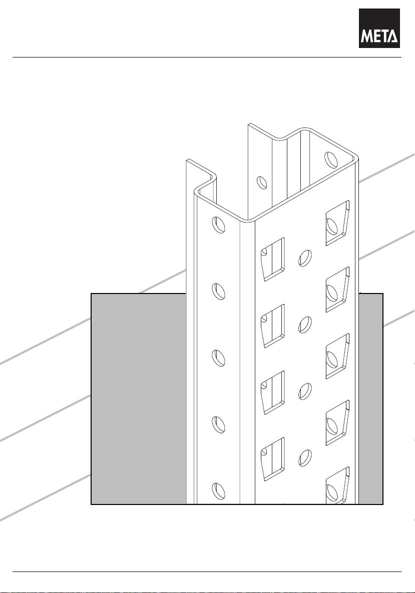
Bodenverankerung
35
Durchschubsicherung: "Leichte Ausführung"
36 bis 37
Durchschubsicherung: "Schwere Ausführung"
38 bis 39
Rammschutz und Pfostenschutz
40
Rammschutzmittelteil und Stützkonsole
41
U-Rammschutz
42
Typenschild
43
Stand 05.2008
Index
Indice
Holme: 85/17, 85/25, 100/20, 120/20, 140/15, 155/17
Rahmenhöhe für Rahmen 120/20, 120/25:
Rahmenhöhe für Rahmen 120/20, 120/25:
ACHTUNG: / CAUTION: / ATTENTION :
Zubehör-Teile für Multipal S sind separat ausgeführt:
AUFBAU-und BEDIENUNGSANLEITUNG META-Multipal S “Zubehör” Nr. 95312
Accessories for Multipal S are listed separately:
ASSEMBLY and OPERATING INSTRUCTIONS META-Multipal S "Accessories" No. 95312
Les accessoires pour Multipal S sont présentés séparément :
INSTRUCTIONS DE MONTAGE ET D'UTILISATION META-Multipal S "accessoires" Numéro 95312
Technische Änderung vorbehalten.
Subject to technical changes
Sous réserve de modifications techniques
2
Page 3

Das Lagersystem
Notizen
Stand 05.2008
Notes
Notes
3
Page 4
Das Lagersystem
Benötigtes Werkzeug
Stand 05.2008
Tools required
Les outils indispensables
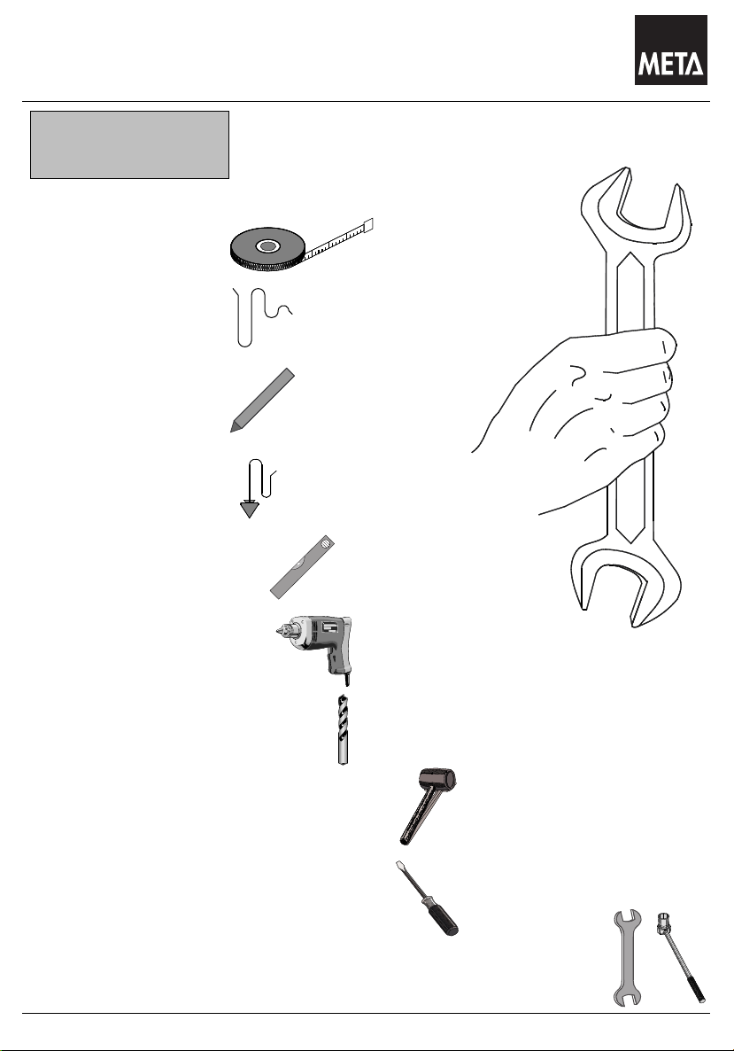
Benötigtes Werkzeug
Tools required
Outils indispensables
Maßband
Measuring tape
Mêtre
Schnur
Cord
Mêtre-ruban
Kreide
Chalk
Craie
Lot
Plumb - Line
Fil à plomp
Wasserwaage
Water level
Niveau à bulle d´air
Schlagbohrmaschine
Percussion drill
Perceuse à percussion
Schlagbohrer Ø 10 / 12 / 14
Percussion drill bits Ø 10 / 12 / 14
Foret à percussion Ø 10 / 12 / 14
Kunststoff- oder Gummihammer
Plastic or rubber hammer
Marteau en plastique ou en caoutchouc
Schraubendreher
Screwdriver
Tournevis
Maul- und Steckschlüssel SW 10 / 13 / 15 / 17 / 18 /19 / 22
Open- jawed and box spanners,sizes 10 / 13 / 15 / 17 / 18 / 19 / 22
Clè à fourche et clé à pipe ( à douille ), ouverture 10 / 13 / 15 / 17 / 18 / 19 / 22
4
Page 5

Das Lagersystem
Wichtige Hinweise Sicherheitsregeln für die Aufstellung und
Stand 05.2008
Bedienung von META-Regalen
Lesen Sie vor dem Aufbau Ihrer META - Regale unbedingt die in
dieser Anleitung aufgeführten Informationen.
Bitte halten Sie sich bei dem Aufbau und bei der späteren
Nutzung exakt an die Angaben in dieser Anleitung, den
Hinweisen in unseren Auftragspapieren sowie den Belehrungen
durch unser Fachpersonal.
Die von META gelieferte Regalteile dürfen nur ihrem
Verwendungszweck entsprechend eingesetzt werden. Für
unsachgemäßen Einsatz, Nutzung oder Montage übernimmt
META keine Gewährleistung.
Alle Angaben in dieser Anleitung gelten nicht für Regale in
Außenaufstellung, bzw. Regale, die zusätzlich durch Wind,
Schnee, Erdbeben oder andere Zusatzlasten beaufschlagt sind.
In solchen Fällen ist eine individuelle Dimensionierung durch den
Hersteller erforderlich.
Durch Umbau, bzw. Neuaufstellung unserer Regale an einem
anderen Ort können sich die Bedingungen für die Nutzung und
Belastung ändern.
Bei Umbau der Regalanlage bzw. Unstimmigkeiten beim Aufbau,
sind META-Fachleute zu Rate zu ziehen.
Der Aufbau sowie der Umbau der Regale darf nur im
unbeladenen Zustand nach unseren beiliegenden Aufbau- und
Bedienungsanleitungen vorgenommen werden.
Die Beladung der Regale darf erst nach völligem
Montageabschluss vorgenommen werden.
Der Aufbau der Regale sollte durch mindestens 2 Personen
erfolgen. Gute Dienste leistet dabei ein hüfthöher Tisch, oder
zwei freistehende Böcke, auf denen die Bauteile zur Vormontage
aufgelegt werden können.
Beim Zusammenbau der Einzelteile darf keine rohe Gewalt durch
Einschlagen mit einem Metallhammer, oder durch Hebelstangen
angewendet werden. Verwenden Sie grundsätzlich einen
Gummihammer oder eine weiche Holzzwischenlage.
Unabhängig vom Höhen - Tiefenverhältnis müssen alle Regale
verdübelt werden.
Um Personen- und Sachschäden abzuwenden, haben wir uns als
Hersteller von Regalanlagen den vom RAL anerkannten Güteund Prüfbestimmungen der RAL-RG 614 unterworfen.
Bei der Planung von Regalanlagen sind die "Richtlinien für
Lagereinrichtungen und -geräte BGR 234" des Hauptverbandes
der gewerblichen Berufsgenossenschaften, Stand 10/88, sowie
die einschlägigen Arbeitsstättenverordnungen verbindlich und die
allgemeinen Unfallverhütungsvorschriften zu beachten.
Von META werden die maximalen Stützlasten und
Flächenpressungen am Fußboden vorgegeben. Sie als Betreiber
müssen dafür Sorge tragen, dass diese Belastungen vom Boden
des Aufstellplatzes sicher aufgenommen werden können. Bei
fehlenden Angaben darf META von einer zulässigen
Fußbodenpressung von mindestens 50 Kg/cm² ausgehen.
Verkehrswege in Regaleinrichtungen sind mindestens 1,25m,
Nebengänge mindestens 0,75m breit auszulegen. Der
Sicherheitsabstand zu Fördermitteln muss mindestens 0,50m auf
jeder Seite betragen.
Die angegebenen, maximal möglichen Fach- und Feldlasten
dürfen nicht überschritten werden.
Bei der Montage von Fachwerkrahmen für Multipal müssen Sie
darauf achten, dass die Schrauben nicht überdreht werden. Die
Schrauben werden zunächst handfest vormontiert, und dann
später mit einem Schraubenschlüssel 1 bis 2 Umdrehungen
nachgezogen.
Regale mit einer Fachlast von mehr als 200 Kg oder einer
Feldlast von mehr als 1.000Kg müssen mit einem Typenschild
gekennzeichnet sein. Typenschildangaben: Hersteller, Baujahr
oder Kommissioniernummer, zulässige Fach- und Feldlasten.
Das mitgelieferte Typenschild ist deutlich sichtbar anzubringen.
Bei korrosionsaktiven Industrieböden (z.B. Magnesitböden) muss
eine Isolierung der Stützenfußbereiche vorgesehen werden. Die
Gebrauchsanleitung der Fußbodenhersteller ist verbindlich zu
beachten.
Regalanlagen dürfen nur nach den ihrer Bestimmung zugrunde
liegenden Maßgaben belastet werden. Die Beladung der Regale
sollte gleichmäßig vorgenommen werden, da die statische
Auslegung auf der Annahme einer gleichmäßig verteilten
Flächenbelastung beruht. Punktförmige Stoßlasten und
Schiebelasten sind daher grundsätzlich zu vermeiden.
Regalrahmen und -fächer, insbesondere Fachböden dürfen nicht
von Personen betreten werden.
Beschädigte und verformte tragende Bauteile einer Regalanlage
müssen umgehend ausgetauscht werden, da die Belastbarkeit
nur im einwandfreien Zustand von META garantiert wird.
Gemäß §10 Prüfung der Arbeitsmittel des
Gerätes- und Produktsicherheitsgesetzes unterliegen Regale der
Prüfpflicht.
Wir empfehlen:
- monatliche Prüfung auf Beschädigung durch den Betreiber
und
- jährliche Inspektion durch den Hersteller
Jährliche Inspektionspflicht für Lagereinrichtungen
Der Arbeitgeber ist dazu verpflichtet, sämtliche
Lagereinrichtungen - d.h. elektrisch angetriebene sowie
statische Regale - systematisch und regelmäßig zu
inspizieren. Wenn vom Regalhersteller aufgrund der
Konstruktion oder der Einsatzbedingungen keine
verschärften Inspektionen gefordert werden, sind die
Regelungen der BGR 234 sowie der Normentwürfe DIN
EN 15512, DIN EN 15620, DIN EN 15629 und im
Besonderen der DIN EN 15635 einzuhalten. Laut der
Betriebssicherheitsverordnung (BetrSichV) trägt der
Arbeitgeber die Verantwortung für die Sicherheit seiner
Lagereinrichtung. Regale müssen somit mindestens alle
12 Monate durch einen Experten inspiziert werden.
META bietet diese Experteninspektion durch einen
verbandsgeprüften Regalinspektor an. Zu näheren
Informationen: www.regalinspektion.de
Auf verzinkten Regalböden oder Paneelen dürfen nicht
unmittelbar Lebensmittel gelagert werden.
Die maximal zulässigen Bodenunebenheiten am Aufstellort sind
der DIN 18202, Tabelle 3, Zeile 3 zu entnehmen.
5
Page 6
Das Lagersystem
Instructions Safety Rules for the mounting and handling of META
Stand 05.2008
shelves
Safety Rules for the mounting and handling of META shelves
Please read the information presented in this guideline thoroughly
before you start mounting your META shelves. Please follow in
the course of mounting and during the utilization of the shelves
exactly the advice given in these guide-lines and follow the
instructions in our order documents as well as the advice given by
our technical experts.
The shelf components supplied by META are allowed to be
utilized only in the framework of the technical purpose intended.
META does not accept any warranty for improper handling,
utilization or mounting.
All details in these instructions do not apply to outdoor racks or
racks that are additionally subject to stress by wind, snow,
earthquakes or other additional loads. In such cases, individual
dimensioning by the manufacturer is essential.
It is possible that the conditions for the utilization of the shelves
are changed, when they are placed at a different location, when
they are altered in their construction or when they are newly
erected.
In case the construction of the shelves is altered or when
difficulties are encountered during erection, you are strongly
advised to ask for META experts to assist you.
Mounting and erection work is allowed to be carried out only when
the shelves are empty, according to our Mounting and Handling
Instruction Sheets attached.
The shelves are permitted to be loaded only after the mounting
work has completely been completed.
For the mounting of the shelves, a minimum of two persons is
required. Very useful in this connection is a table with a height up
to the hips, or two free standing horses, on which the individual
components can be placed for the preliminary mounting.
When joining the various components, it is not allowed to use
great force to forcibly insert by means of a metal hammer or by
using a lever. On principle, use only a rubber hammer or a soft
wooden intermediary layer.
Independent of the ration of height and depth, all shelves must be
fastened by dowels.
We, as the manufacturers of shelf constructions, have submitted
and dedicated ourselves to the Quality and Testing Regulations
RAL-RG 614, recognized by the RAL Institute, in order to prevent
injuries of persons and material damage.
In the course of planning shelf installations, the "Guidelines for
Storage Installations and devices BGR 234" of the Main
Association of the industrial trade organizations, status 10/88, as
well as the relevant regulations governing the prevailing
conditions at the workplace are binding, and the general
regulations for the prevention of accidents must be adhered to.
META states the maximum supporting loads and the pressures
allowed to be exerted on the surfaces of the areas at the ground.
The customer and user must ensure that the bearing capacity of
the ground at the place of mounting can safely withstand these
loads. Unless specific details are made to the contrary, META
assumes that the minimum permissible floor pressure is 50 kg/
cm².
The minimum width for traffic aisles in shelf constructions is 1.25
m, the minimum width of sub-aisles is 0.75 m. The minimum
safety distance between the means of transportation and the
shelves must be 0.50 m on either side.
The maximum possible shelf and field loads as stated are not
allowed to be exceeded.
When mounting the frames for Multipal you must make sure that
the screws are not excessively tightened. Initially, the screws
preliminarily mounted hand-tight, afterwards they are re-tightened
by means of a spanner by one or two rotations.
Shelves with a shelf load of more than 200 kg or a field load of
more than 1000 kg must be equipped with a name plate.
The necessary details on this name plate are as follows:
Manufacturer, year of construction or number of commissioning,
admissible shelf and field loads. The name plate supplied must be
attached at a conspicuous place of the construction.
In the case of corrosive active industrial floors (e.g. magnesite
floors), an insulation of the support base areas must be provided
for. The instructions for use, issued by the floor manufacturers,
must be strictly observed.
Shelf constructions are allowed to be loaded only in strict
compliance with the purpose intended on the basis of the details
specified. Loading of the shelves should be carried out in a
uniform manner, because the static design is based on
assumption that the area loading will be effected uniformly.
Impact loads on certain points only and sliding loads must, on
principle, be avoided.
Persons are not allowed to stand or walk on the shelf frames and
shelf boards.
Bearing components that are damaged or deformed out of shape
must be replaced without delay because the nominal load
capacity is warranted by META on the condition that the complete
construction is in perfect shape.
According to §10 Testing of Equipment of the Appliance and
Product Safety Act, the testing of racks is obligatory.
We recommend:
- monthly inspection for damage performed by the plant operator
and
- yearly inspection by the manufacturer
Mandatory annual inspections for warehouse equipment
The employer is obligated to inspect all of its warehouse
equipment - including all electric-powered vehicles as well as
static shelving - systematically and at regular intervals. Providing
that the racking manufacturer does not stipulate that additional
inspections are to be made due to the specific design of the
racking or its conditions of use, the following regulations must be
met: BGR 234 (stipulated by the German employer's liability
insurance association) as well as Draft Standards DIN EN 15512,
DIN EN 15620, DIN EN 15629 and, in particular, DIN EN 15635.
According to the terms of the German Ordinance on Industrial
Safety and Health (BetrSichV), the Employer is responsible for
the safety of its racking equipment. For this reason, racking
systems must be inspected by an expert every 12 months. META
offers an expert inspection service conducted by an Associationcertified racking inspection body. For more information, please
go to www.regalinspektion.de
Food is not allowed to be placed directly on galvanized shelves or
panels. For the maximum permissible deviations from levelness
conditions at the place of mounting, see DIN 18202, Table 3, line
3.
.
6
Page 7

Das Lagersystem
Indications et règles de sécurité pour le dressage et
Stand 05.2008
l'utilisation des rayonnages META
Avant de procéder au dressage de vos rayonnages META,
veuillez lire impérativement les informations et "règles de
sécurité" fournies dans les présentes instructions. Veuillez
également, aussi bien lors du dressage que l'utilisation ultérieure
de vos rayonnages, vous conformer exactement aux informations
fournies dans les présentes instructions, aux indications figurant
dans nos documents de commande ainsi qu'aux enseignements
fournis par notre personnel technique.
Les éléments de rayonnage livrés par META ne doivent être
utilisés que conformément à leur destination. META décline toute
responsabilité pour tous les dommages qui résulteraient d'une
exploitation, d'une utilisation ou d'un montage incorrects du
rayonnage.
Toutes les indications fournies dans les présentes instructions ne
s'appliquent pas aux rayonnages implantés à l'extérieur ou à ceux
qui sont soumis à la charge supplémentaire du vent, de la neige,
d'un tremblement de terre ou à toute autre charge
supplémentaire. Dans les cas suscités, un dimensionnement
individuel par les soins du constructeur sera nécessaire.
La reconstruction et le nouveau dressage de nos rayonnages sur
un autre site sont susceptibles d'entraîner la modification des
conditions d'utilisation et de charge.
Faites appel à des spécialistes de META à toute reconstruction
de l'installation à rayonnages ou en cas d'irrégularités lors du
dressage.
Le dressage et la reconstruction des rayonnages ne doivent être
effectués que lorsque ces derniers sans vides, conformément à
nos instructions de dressage et d'utilisation ci-jointes.
Le chargement des rayonnages ne doit être effectué qu'après la
fin totale des travaux de montage.
Le dressage des rayonnages doit être effectué par deux
personnes au moins. De précieux services vous seront fournis
dans ce contexte par une table présentant la hauteur la hauteur
de la hanche ou deux chevalets librement implantés, sur lesquels
vous pourrez poser les éléments pour le montage préliminaire.
Au moment de l'assemblage des différents éléments, il ne vous
est pas permis d'exercer une violence brute, par exemple par des
frappes à l'aide d'un marteau métallique ou par l'utilisation d'une
barre de relevage utilisée comme bras de levier. D'une manière
générale, utilisez une massette en caoutchouc ou une lame
intercalaire en bois tendre.
Indépendamment des conditions de hauteur et de profondeur,
vous devez impérativement cheviller tous les rayonnages.
Dans le but de vous éviter les dégâts humains et matériels, nous
nous sommes conformé comme constructeur d'installation de
rayonnages aux dispositions de qualité et d'essai RAL-RG 614,
reconnues par le RAL.
L'étude des installations de rayonnage est soumise
obligatoirement aux "directives relatives aux installations et
appareils de stockage BGR 234" du Regroupement principal des
unions professionnelles industrielles, situation 10/88 ; conformezvous également aux ordonnances afférentes relatives aux lieux
du travail et aux dispositions générales relatives à la prévention
des accidents de travail.
La société META vous indique les valeurs maximales pour la
charge d'appui verticale et la pression superficielle au plancher.
En votre qualité d'exploitant du rayonnage, vous êtes tenus de
prendre les mesures nécessaires afin que ces charges exercées
au sol du lieu de dressage puissent être supportées sûrement.
Dans le cas de l'absence d'information, la société META admettra
une pression superficielle minimale sur le plancher de 50 Kg/cm2.
Au sein des installations de rayonnages, vous devez
dimensionner les voies de circulation à une largeur minimale de
1,25 m et de 0,75 m pour les passages secondaires. La distance
de sécurité minimale vis-à-vis des engins de transport doit être de
0,50 m sur les deux côtés.
Il ne vous est pas permis de dépasser les charges maximales
possibles par casier et par niveau, telles qu'elles sont indiquées.
Lors du montage du cadre de charpente pour Multipal, faites
impérativement attention à ne pas fausser les vis. Montez dans
un premier temps les vis en les serrant à la main, puis serrez ces
dernières à fond plus tard 1 ou 2 tours à l'aide d'une clé à vis.
Les rayonnages dotés d'une charge par niveau supérieur à 200
kg ou une charge par casier supérieure à 1.000 kg doivent
impérativement être repérés par une plaque signalétique.
Indications sur la plaque signalétique : Constructeur, année de
construction ou numéro de commission, charges par casier et par
niveau autorisées. La plaque signalétique fournie avec le
rayonnage doit être montée à un endroit bien visible.
Sur les sols industriels favorisant la corrosion (par exemple les
planchers magnésiens), il sera nécessaire de prévoir un
isolement des zones de pieds des appuis. Les instructions du
fabricant du plancher doivent être respectées obligatoirement.
Les installations de rayonnages ne doivent être soumises aux
charges que conformément aux prescriptions conformes à leur
destination. Le chargement des rayonnages doit être effectué
uniformément, car la conception statique se fonde sur la
présomption d'une charge superficielle uniformément répartie.
Par conséquent, évitez en général les charges par à-coups et les
charges coulissantes ponctuelles.
Il n'est pas permis aux personnes d'accéder aux cadres et aux
casiers des rayonnages, notamment aux fonds de casier.
Remplacez impérativement et immédiatement les pièces
porteuses endommagées et déformées d'une installation de
rayonnages, car la capacité de charge ne vous est garantie par
META que dans l'état technique impeccable de ces éléments.
Conformément à l'article 10 portant sur l'examen des moyens de
travail de la Loi sur la sécurité des appareils et des produits, les
rayonnages sont soumis à l'obligation de contrôle.
Nous vous recommandons :
-un contrôle mensuel de la présence éventuelle de dommages
par l'exploitant
et -une inspection annuelle par le constructeur
Obligation d'inspection annuelle pour les installations de
rayonnages
L'employeur est tenu d'effectuer une inspection systématique et
régulière de toutes les installations de rayonnages - c'est-à-dire
les rayonnages à commande électrique et statiques. Si le
constructeur du rayonnage n'exige pas d'inspections plus
rigoureuses en raison de la construction du rayonnage ou de ses
conditions d'exploitation, les inspections doivent se conformer
aux règlements BGR 234 ainsi qu'aux projets de normes DIN EN
15512, DIN EN 15620, DIN EN 15629 et, particulièrement, à la
norme DIN EN 15635. En vertu de l'ordonnance allemande
relative à la sécurité dans les entreprises (BetrSichV),
l'employeur est responsable de la sécurité de ses rayonnages.
Les rayonnages doivent ainsi faire l'objet d'une inspection par un
expert au moins une fois tous les 12 mois. META propose ces
inspections d'expert par les soins d'un inspecteur de rayonnage
agréé par le regroupement professionnel. Pour de plus amples
informations : www.regalinspektion.de.
Il ne vous est pas permis de stocker des aliments directement sur les
fonds de casier zingués ou sur les panneaux de lambris.
Les inégalités de sol maximales au lieu de dressage du rayonnage
vous sont indiquées par la norme DIN 18202, tableau 3, ligne 3.
7
Page 8
Das Lagersystem
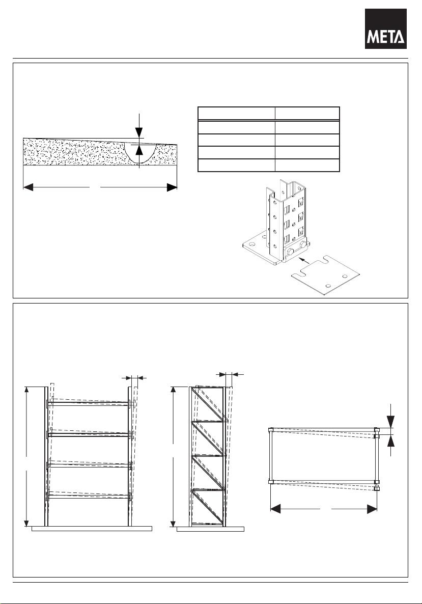
Unbedingt beachten
L m X mm
< 1,0 max. 4
> 1,0 bis 4,0 max. 10
> 4,0 bis 10,0 max. 12
> 10,0 bis 15,0 max. 15
Stand 05.2008
Important regulations
Réglémentations importantes
Aufstellfläche / Floor / Sol
X
zulässige Bodenunebenheiten nach DIN 18202
permissible floor unevenness to DIN 18202
inégalités au sol nautorisés selon DIN18202
L
Ausgleichsblech
base plate
sémelle
Bodenunebenheiten mit Ausgleichsblechen
ausgleichen.
level out unevenesses with the help of base plates
égalisez des inégalités à l’ aide de sémelles
max. zulässige Abweichungen in Längs-und Tiefenrichtung von lotrecht stehenden Regalen.
maximal permissible deviation with longitudinal and depth direction with vertical racks
déviation maximale admissible au sens longitudinal et au profondeur des rayonnages verticaux
H / 500
H / 400
H / 350
H
H
Regal-Längsrichtung
longitudinal direction of racks
sens longitudinal des rayonnages
Regal-Tiefenrichtung
depth direction of racks
profondeur des rayonnages
8
L
Regaldraufsicht
Top view
Vue de dessus
Page 9
Das Lagersystem
Hinweise auf Beladerichtung
Stand 05.2008
Indication concerning direction of loading
Détails concernant la direction du chargement
Höhe
height
hauteur
Regalvorderseite
frontside of the shelving
front du rayonnage
Breite
length
largeur
Tiefe
depth / profondeur
Achtung :
Diagonale stehen grundsätzlich
in Beladerichtung
Attention:
Diagonal must always be into direction of loading
Attention:
Les diagolales doivent toujours être situées
en direction du charge ment.
Beladerichtung
direction of loading
direction du chargement
Beladerichtung
direction of loading
direction du chargement
Einfachregal
racking single sided run
rangée simple
Beladerichtung
direction of loading
direction du chargement
Doppelregal
racking double
sided run
rangéee double
9
Page 10
Das Lagersystem
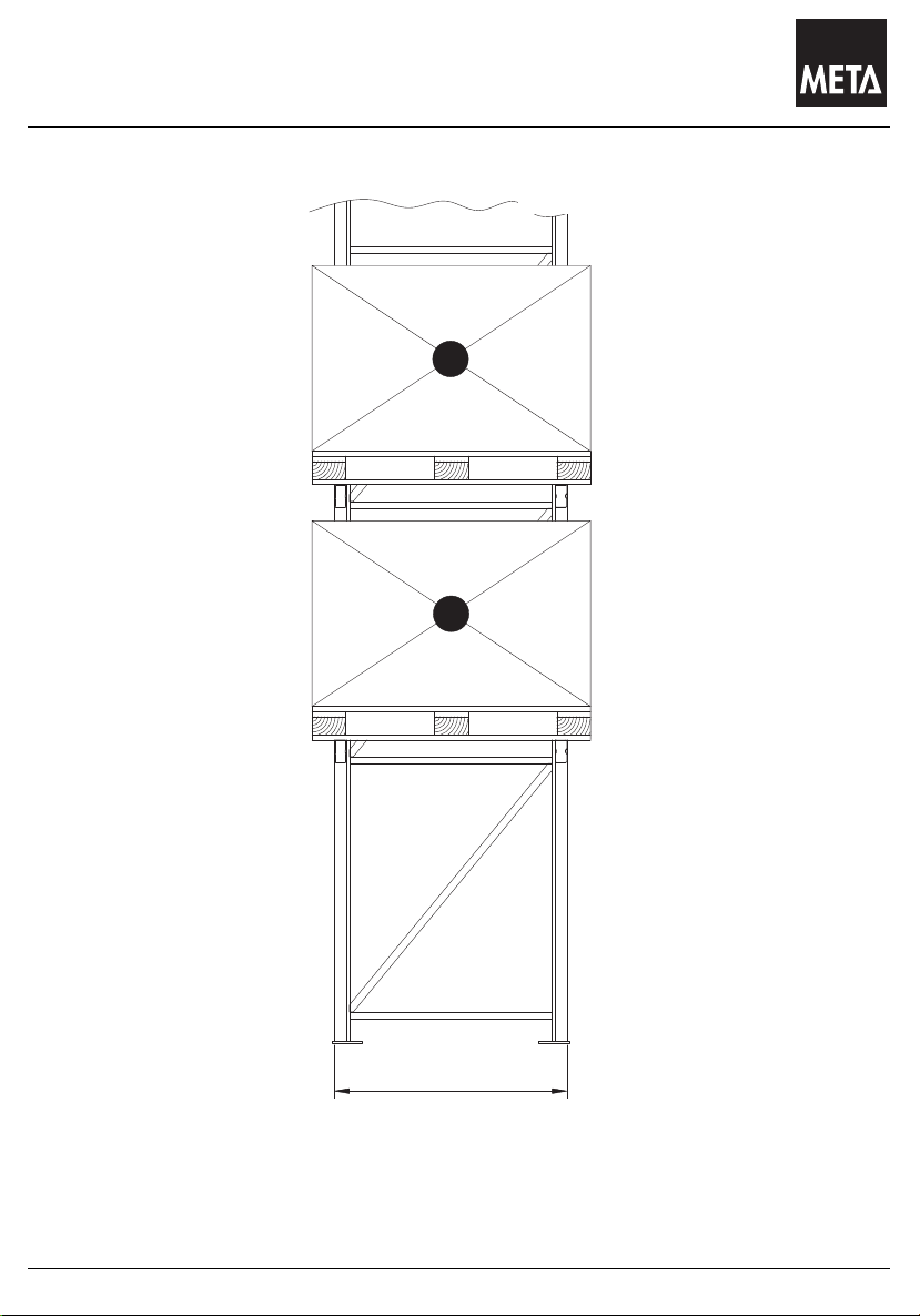
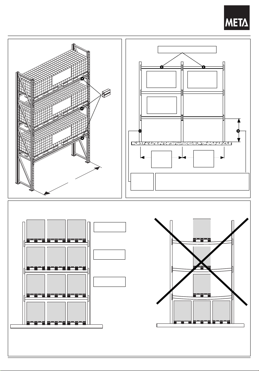
Darstellung einer symmetrischen Lasteinlagerung
ts
Stand 05.2008
Presentation of symmetrical load storage
Représentation d'un emmagasinage de charge
S = Schwerpunkt der Palette
S = Centre of gravity of the pallet
S = centre de gravité de la palette
S
ideale Position
ideal position
gleiche Überstände zu
beiden Seiten
equal projections on both
sides
Même porte-à-faux sur les
deux côtés
S
position idéale
ideale Position
ideal position
position idéale
Zu beachten ist, das die Paletten gleichmässigen Überstand bekommen. Somit
ist die ideale Position (siehe Bild oben) gewährleistet.
Please make sure that the pallets project equally on both sides to ensure an ideal position (see
above illustration).
Il faut faire attention à ce que les palettes présentent le même porte-à-faux sur les deux côtés.
C'est ainsi qu'est garantie la position idéale pour la palette (voir image du haut).
10
Page 11
Das Lagersystem
Systemzubehör : Einbau Durchschubsicherung
Stand 05.2008
System parts : Assembly back stop
Eléments du systeme : Fixiation de la butée de palette
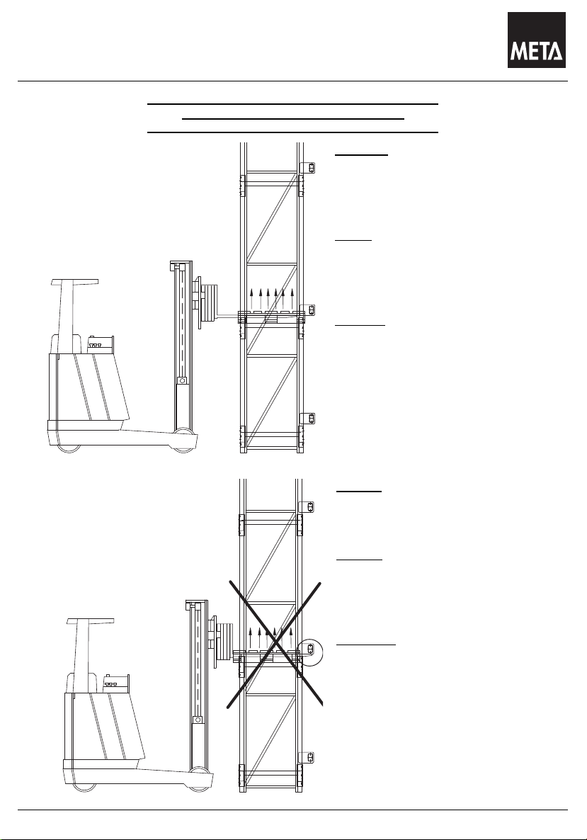
Auf richtige Bedienung des Regals achten!
Make sure the rack is operated correctly!
Faite attention à une bonne utilisation du rayonnage !
Richtig!
Palette und Ladegabel können
beim anheben Durchschubsicherung nicht zerstören.
Right!
The pallet and the lifting fork cannot
destroy the push-though safety
device while lifting.
Correct!
La palette et la fourche du chariot
élévateur, lors du levage, ne sont
pas en mesure de détruire la butée
de palettes.
Falsch
Ladegabel kann beim anheben
Durchschubsicherung zerstören.
Wrong!
The lifting fork can destroy the
push-though safety device while
lifting.
Incorrect!
La fourche de chariot élévateur peut
détruire la butée de palettes lors du
levage.
11
Page 12
Das Lagersystem
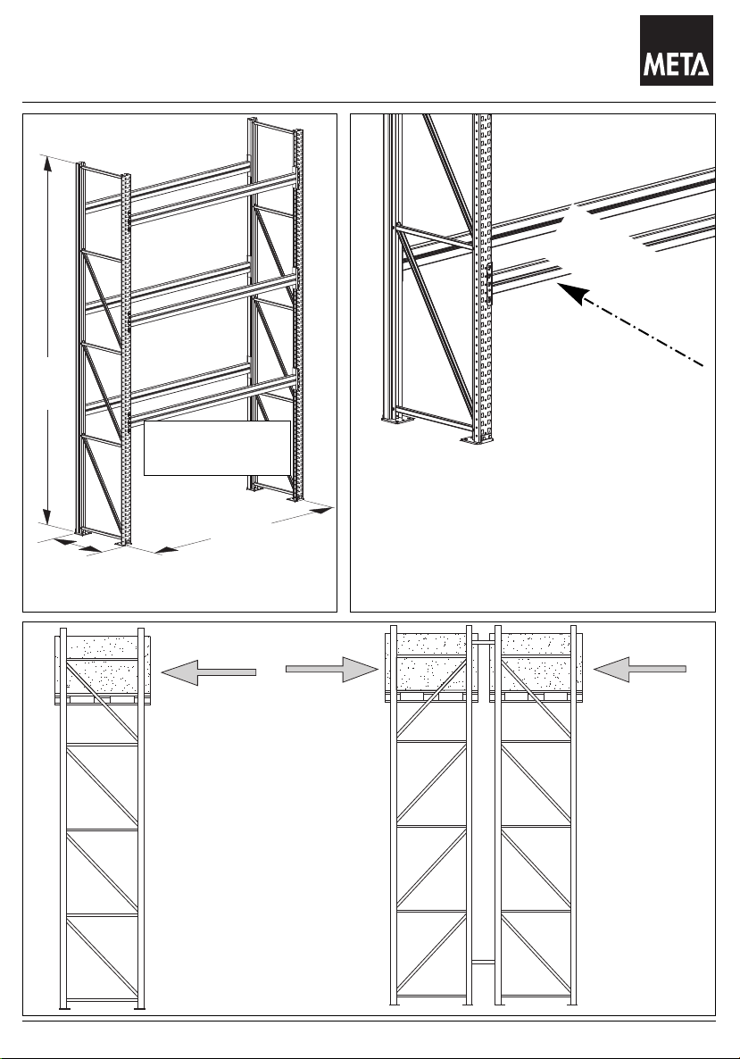
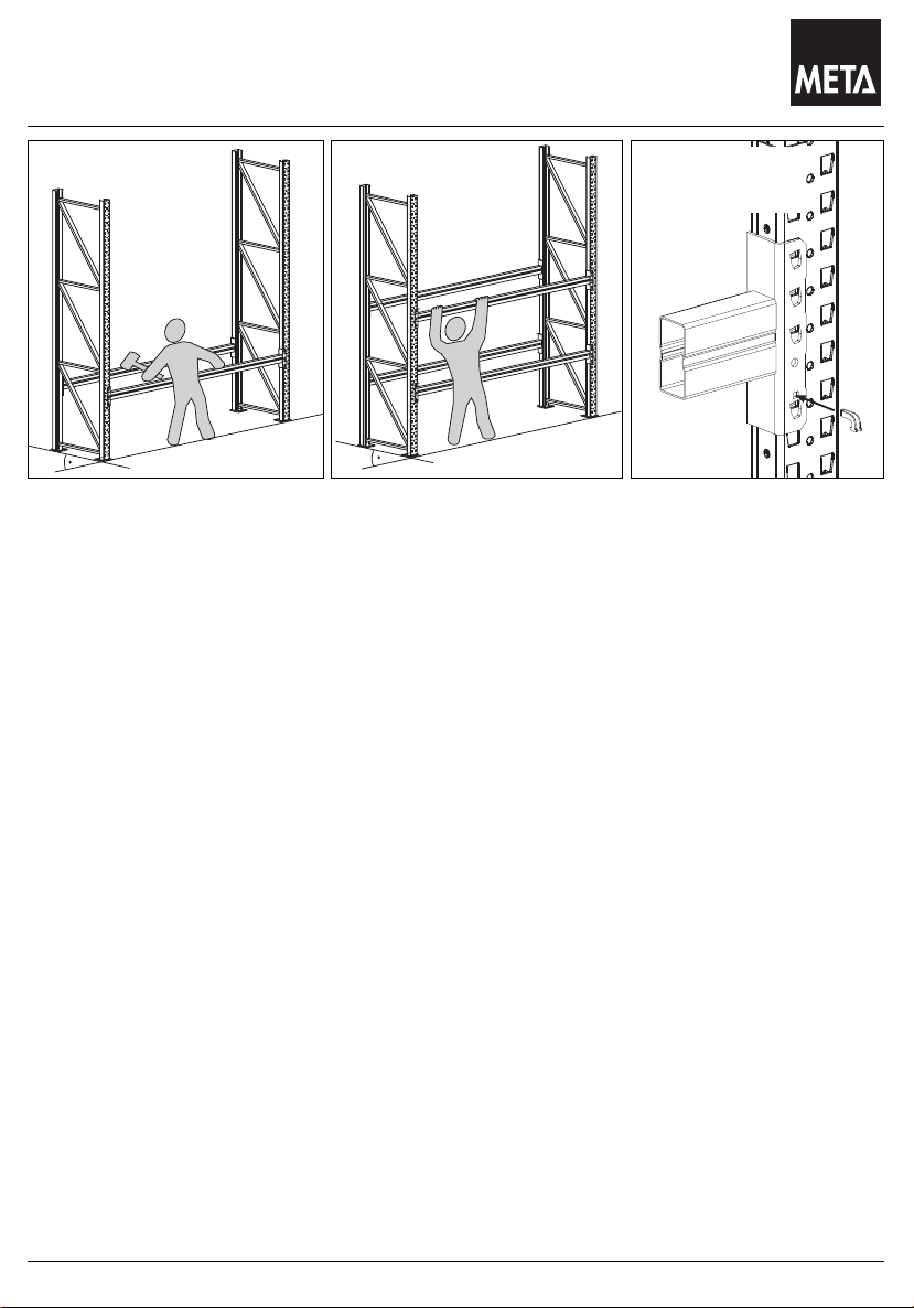
Aufbau von Regalen
Stand 05.2008
Assembly of racks
Montage de rayonnage
Sicherungsstift
Safety pin
goupille de sécurité
1. AUFBAU:
Mit Maßband und Kreide genauen Standort der Regale auf dem Fußboden anzeichnen.
1.1 Aufstellen des Grundregals:
Zwei Rahmen mit Holmabstand aufrichten.
Unterstes Holmpaar in gewünschter Fachhöhe einhängen.
Mit Gummihammer festsetzen. Sicherungsstifte einführen.
1.2 Aufstellen weiterer Anbauregale:
Rahmen des Anbauregals aufrichten.
Unterstes Holmpaar wie unter 1.1 einhängen, festsetzen und sichern.
1.3 Verbinden von Doppelregalen:
2. Regalzeile paralell zur 1. Regalzeile mit gewünschtem Abstand aufstellen und
mit Distanzstücken verbinden (siehe Seite: 34)
1.4 Einsetzen weiterer Holme:
Alle weiteren Holme in der vorgesehenen Fachhöhe einhängen, festsetzen und sichern.
1.5 Ausrichten:
Regalzeile auf endgültigem Standort ausrichten.
Höhenunterschiede des Bodens durch Unterlegbleche ausgleichen.
zulässige Toleranzen :
a - bei Bedienung mit normalen Gabelstablern in Achsrichtung und senkrech ± 10 mm.
b - bei Bedienung mit schienengeführten Hochraumstablern in Achsrichtung und
senkrecht ± 5 mm.
1.6 Bodenverankerung:
Regale müssen mit Bodenankern verdübelt werden. (siehe Seite: 35)
12
Page 13

Das Lagersystem
Aufbau von Regalen
Stand 05.2008
Assembly of racks
Montage des rayonnages
1. Assembly:
Draw the exact location of the racks on the floor with the help of a measuring tape.
1.1 Assembly of the starter bay:
Assembly two frames with the distace of a beam. Put in the lowest beam pair at the desired
level. Fix it with a rubber hammer. Put in the safety pin.
1.2 Assembly of additional bays:
Assemble the frames of the additional racks. Put in the lowest beam pair according to 1.1,
fix it and secure it.
1.3 Connection of double bays:
Assemble the second rack line parallel to the first rack line at the desired distance and
connect it with spares (page 34).
1.4 Assembly of further beams:
Put in all further beams at the adequate height of partition, fix it and secure it.
1.5 Lining up:
Line up on the definite location. Level out unevenesses with the help of base plates.
Permitted tolerances:
a. with operation of normal fork-lift trucks with axle direction and vertical ± 10mm
b. with operation of trucks for high rooms on trails in axle direction and vertical ± 5mm
1.6 Anchorning with floor:
Racks must be plugged with anchors for the floor (page 35).
1. Montage
Dessinez le sol la définitive des rayonnages avec le mêtre et la craie
1.1 Montage de I’ élément de base:
Elevez deux échelles avec la distance de la lisse. il faut accrocher la paire de lisses
la plus basse au niveau désiré. Fixez avec un marteau en caotchouc.Introduisez les
goupilles de sécurité.
1.2 Montage des éléments supplémentaires:
Elevez les échelles de I’ èlèment supplémentaire. Accrochez la paire de lisse la plus basses
selon 1.1, fixez-la et assurez-la.
1.3 Assembler des rayonnages doubles:
Assemblez la deuxiéme ligne de rayonnages parallèlement à la première ligne à la distance
désirée avec une entretoise. (page 34)
1.4 Montage de lisses supplémentaires:
Accrochez toutes lisses supplémentaires au niveau prévu, fixez-les et assurez-les.
1.5 La mise au point:
La ligne du rayon doît être mise au point de la location définitive.
Egalisez des inégalités à I’ aide de sémelles.
Tolérances admissibles:
a. avec une opération de chariots élévateurs à fourches normaux en direction
de I’axe et vertical ± 10mm
b. avec opération de chariots élévateurs au guide rails pour des halles
de dépot hautes en direction de I’ axe et vertical ± 5mm
1.6 Ancrage dans le sol:
Les rayonnages doivent être chevillés avec desvancrages de sol.(page 35)
13
Page 14
Das Lagersystem
F
(kg)
F
(kg)
F
(kg)
F
(kg)
F
(kg)
F
(kg)
F
(kg)
F
(kg)
F
(kg)
Hinweis zu Belastungen
Q
(kg)
Q
(kg)
Q
(kg)
Stand 05.2008
Load capacities
Capacités du chargement
Holme / Spar / Longerons
F = (kg)
F =
F =
Σ F = Q ( kg )
F
(kg)F(kg)F(kg)
F
(kg)F(kg)F(kg)
F
(kg)F(kg)F(kg)
(kg)
(kg)
Fach
compartment
case
Fach
compartment
case
Feld
bay
travée
L
Rahmen
frame
échelle
Fachhöhe = freie Knicklänge
height of compartment = free buckling length
hauteur d’ alvéole = longueur libre de flambage
= Q ( kg )
Fach
compartment
case
Feld
bay
travée
Q
(kg)
= Q ( kg )
Q
(kg)
= Q ( kg )
Gleichmäßig verteilte Last
Evenly distributed load
Charge uniformément répartie
F = Palettenlast
Weight of pallet
Poids de la palette
14
Q = Fachlast
Load per level
Charge par niveau
Page 15

Das Lagersystem
Hinweis zu Belastungen
75%
75%
110
200
Æ10
110
200
Æ10
Stand 05.2008
Load capacities
Capacités du chargement
80%
87%
1-Feld Regal mussen
mit 2 Schraubankeren
h
je Fussplatte verankert
werden.
h
h
h
h
h
87%
Die Feldlasten gelten für Regalzeilen mit min. 4 Feldern,
und min. 2 Holmebenen bei gleichmäßigen Fachhöhen (h)!
Abminderung der Belastungswerte für Auflagen und
Ständer, nachden hier angegebenen Prozenten den
Tabelenwerte.
-The load per bay are only valid for rows with at least
4 bays and at least 2 levels of beams with equal heights (h)
of compartments. Reduction of the load values for supports
and stands, according to the percentages stated here with the
value in the table.
-La capacitées de travée sont valables seulement s’il y a au
moins 4 travées et au moins 2 niveaux de lisses avec les
memes hauteurs (h) des alvéoles. Réduction des valeurs de
charge pour les supports et les pieds-droits selon les
pourcentages indiqués ici avec les valeurs de la table..
Σ Felder <=4, dann sind die angegebenen Prozentwerte
gültig .
Σ Bay <=4, then the given percentage values of are valid.
Σ travée <=4, donc les valeurs données du taux sont valables.
h
h
h
75%
93%
93%
93%
h
h
h
75%
100%
100%
100%
100%
15
Page 16

Das Lagersystem
Holme , Einhängung von Holmen
LHT
mm mm mm
1800
2200
2700
1800
2200
2700
3300
3600
1800
2200
2700
3300
3600
1800
2200
2700
3300
3600
LHT
2700
3300
2700
3300
3600
Holmtyp Schachtelprofil
140 / 15 140 50
155 / 17 155 50
100 / 20
120 / 20
Holmtyp Kastenprofil
85 / 15
85 / 20
85
85
100
120
50
50
50
50
Stand 05.2008
Beams , fitting the spars
Lisses , fixiation des lisses
Sicherungsstift
Safty pin
Goupilles de sècuritè
L
A
A
3600
16
Page 17

Das Lagersystem
Notizen
Stand 05.2008
Notes
Notes
17
Page 18

Das Lagersystem
Feldlasten für Rahmen Multipal S
Feldlasten - Rahmenhöhe 8m - bei Fachweiten bis 2700mm
max.Feldlast in kg
Fachhöhe in mm
27500
2500
5000
7500
10000
12500
15000
17500
20000
22500
25000
500 1000 1500 2000 2500 3000
mit 4HS 140/15
SR 120/25
SR 120/20
SR 100/20
SR 85/20
SR 85/17
mit 4HS 140/15
mit 4HN 120/20
mit 4HN 120/20
mit 4HN 100/20
Stand 05.2008
Load per bay for Frame Multipal S
Capacités de travée pour échelle Multipal S
Die angegebenen Feldlasten gelten für die hier beschriebenen Ständer- /
Holmkombinationen bei einer Regalhöhe von 8m und einer Fachweite bis zu 2700mm.
Je nach Holmprofil ergeben sich andere Feldlasten.
Die Werte gelten für Regalzeilen mit mindestens vier Regalfeldern.
The loads per bay are only valid for rack rows with at least
4 bays and the shown combinations of frames and beams
with a height of 8 meters and a glear (length of beam) of
max. 2700mm.
The loads per bay are depending on the combinations of
frames and beams.
Les charges admissibles par élément indiquées ci-dessus
sont valabs pour les combinaisons décrites des Lisses/
échelles pour des rayonnages avec une hauteur totale de
8000 mm et une largeur de champs jusqu’à 2700 mm. Les
charges admissibles varient selon le type de lisse. Ces
valeurs conviennent seulement aux rayonnages composés
d'au moins quatre éléments.
Lors de modifications des conditions citées ci-dessus, les
données de charge par élément varient. Dans de tels cas,
les charges par élément sont déterminées individuellement
par META. Pour les détails, veuillez consulter s´il vous plaît
les formulaires de commande.
18
Bei Abweichungen von den oben vorgegebenen Bedingungen verändern sich die
Belastungsangaben. In solchen Fällen werden die Feldlasten von META individuell
ausgelegt. Einzelheiten entnehmen Sie bitte den Auftragspapieren.
In case of deviations from the above specified conditions,
the field load data will change. In these cases,
the field loads will be individually designed by META.
Please see order documentation for details.
Page 19

Das Lagersystem
Rahmen Multipal S:85/17, 85/20, 100/20, 100/35, 120/20, 120/25
Stand 05.2008
Multipal S frames: 85/17, 85/20, 100/20, 100/35, 120/20, 120/25
Echelle Multipal S: 85/17, 85/20, 100/20, 100/35, 120/20, 120/25
Geschraubter Rahmen
Screwed Frame
Echelle boulonne
85/17, 85/20,
100/20, 100/35
120/20, 120/25
19
Page 20

Das Lagersystem
Fachlast für Holme Multipal S
85-15
85-20
100-20
120-20HS140-15HS155-17
Fachbreite 3600 934
1072 1526 2139 2780
3671
Fachbreite 3300 1077
1239 1766 2471 3033
4000
Fachbreite 2800 1411
1632 2329 2820 3574
4000
Fachbreite 2700 1499
1735 2396 2904 3707
4000
Fachbreite 2200 1908
2287 2815 3438 4000
4000
Fachbreite 1800 2223
2681 3309 4000 4000
4000
85-15
85-20
100-20
120-20HS140-15HS155-17
Fachbreite 3600 919
1057 1503 2112 2780
3671
Fachbreite 3300 1060
1223 1740 2448 3033
4000
Fachbreite 2800 1390
1612 2300 2796 3574
4000
Fachbreite 2700 1477
1714 2372 2880 3707
4000
Fachbreite 2200 2200
2268 2789 3413 4000
4000
Fachbreite 1800 2202
2661 3282 4047 4000
4000
85-15
85-20
100-20
120-20HS140-15HS155-17
Fachbreite 3600 971
1083 1545 2165 3131
4028
Fachbreite 3300 1119
1251 1787 2493 3387
4365
Fachbreite 2800 1464
1647 2349 2843 3935
5085
Fachbreite 2700 1554
1751 2416 3000 4069
5261
Fachbreite 2200 1957
2301 2836 3500 4919
5500
Fachbreite 1800 2277
2696 3331 4098 5500
5500
85-15
85-20
100-20
120-20HS140-15HS155-17
Fachbreite 3600 956
1069 1523 2140 3119
4015
Fachbreite 3300 1102
1236 1764 2471 3375
4352
Fachbreite 2800 1443
1629 2324 2820 3923
5072
Fachbreite 2700 1532
1732 2393 2950 4057
5248
Fachbreite 2200 1938
2284 2812 3439 4906
5500
Fachbreite 1800 2257
2678 3306 4073 5922
5500
Rahmen
SR 85/20
Belastung in KG Fachhöhe 2000mm
Load capacities / Capacités du chargement -Kg
height of partition / hauteur d'alvéole 2000 mm
Rahmen
SR 85/17
Belastung in KG Fachhöhe 2000mm
Load capacities / Capacités du chargement -Kg
height of partition / hauteur d'alvéole 2000 mm
Rahmen
SR 85/20
Belastung in KG Fachhöhe 1500mm
Load capacities / Capacités du chargement -Kg
height of partition / hauteur d'alvéole 1500 mm
Rahmen
SR 85/17
Belastung in KG Fachhöhe 1500mm
Load capacities / Capacités du chargement -Kg
height of partition / hauteur d'alvéole 1500 mm
Stand 05.2008
Load per level for beams Multipal S
Capacités per niveau pour lisses Multipal S
Holm
Holm
Holm
Holm
Holm
Holm
Holm
Holm
Holm
Holm
Holm
Holm
1500
1500
2000
2000
1500
Holm
Holm
Holm
Holm
20
1500
2000
2000
Page 21

Das Lagersystem
Fachlast für Holme Multipal S
85-15
85-20
100-20
120-20HS140-15HS155-17
Fachbreite 3600 1007
1093 1563 2190 3481
4385
Fachbreite 3300 1160
1262 1808 2515 3741
4725
Fachbreite 2800 1516
1661 2368 2865 4296
5450
Fachbreite 2700 1609
1800 2435 3000 4431
5500
Fachbreite 2200 2005
2314 2856 3500 5288
5500
Fachbreite 1800 2331
2750 3400 4122 5500
5500
85-15
85-20
100-20
120-20HS140-15HS155-17
Fachbreite 3600 993
1082 1544 2167 3457
4360
Fachbreite 3300 1144
1250 1787 2495 3717
4699
Fachbreite 2800 1496
1646 2348 2845 4272
5424
Fachbreite 2700 1588
1750 2415 3000 4407
5500
Fachbreite 2200 1987
2300 2835 3465 5263
5500
Fachbreite 1800 2311
2695 3330 4100 5500
5500
85-15
85-20
100-20
120-20HS140-15HS155-17
Fachbreite 3600 1097
1270 1830 2420 3593
4522
Fachbreite 3300 1263
1500 2110 2660 3856
4865
Fachbreite 2800 1648
1880 2570 3070 4415
5500
Fachbreite 2700 1748
1960 2670 3160 4551
5500
Fachbreite 2200 2126
2480 3190 3800 5412
5500
Fachbreite 1800 2465
2900 3620 4320 5500
5500
85-15
85-20
100-20
120-20HS140-15HS155-17
Fachbreite 3600 1087
1190 1720 2310 3574
4500
Fachbreite 3300 1251
1400 2020 2590 3836
4842
Fachbreite 2800 1633
1760 2500 3060 4395
5500
Fachbreite 2700 1732
1830 2600 3160 4531
5500
Fachbreite 2200 2112
2420 3160 3800 5391
5500
Fachbreite 1800 2450
2890 3600 4310 5500
5500
Rahmen
SR 100/35
Belastung in KG Fachhöhe 2000mm
Load capacities / Capacités du chargement -Kg
height of partition / hauteur d'alvéole 2000 mm
Rahmen
SR 100/35
Belastung in KG Fachhöhe 1500mm
Load capacities / Capacités du chargement -Kg
height of partition / hauteur d'alvéole 1500 mm
Rahmen
SR 100/20
Belastung in KG Fachhöhe 2000mm
Load capacities / Capacités du chargement -Kg
height of partition / hauteur d'alvéole 2000 mm
Rahmen
SR 100/20
Belastung in KG Fachhöhe 1500mm
Load capacities / Capacités du chargement -Kg
height of partition / hauteur d'alvéole 1500 mm
Stand 05.2008
Load per level for beams Multipal S
Capacités per niveau pour lisses Multipal S
Holm
Holm
Holm
Holm
1500
Holm
Holm
Holm
Holm
Holm
Holm
Holm
Holm
Holm
Holm
Holm
Holm
1500
2000
2000
1500
1500
2000
21
2000
Page 22

Das Lagersystem
H11a234567
1600 241224
2200 241346
2700 243326
3300 243448
3800 243428
4400 2435410
4900 2445210
5500 2446412
6000 2456212
6600 2457414
7100 2467214
7700 2468416
8200 2478216
8800 2479418
9300 2489218
9900 2 4 8 10 4 20
10400 2 4 9 10 2 20
11000 2 4 9 11 4 22
11500 2 4 10 11 2 22
12000 2 4 10 12 4 24
2
2
2
2
2
2
2
2
2
2
2
2
2
2
2
2
2
2
2
2
Rahmenausführung Multipal S, Teileübersicht, Mengen in Stück
85/17
85/20
100/20
100/35
Ständerprofil Fussplatte Ständerhöhen
6 mm
6 mm
8 mm
8 mm
alle Ständerhöhen
bis 8200 mm
ab 8800 mm
alle Ständerhöhen
Stand 05.2008
Framework Multipal S , component programme, quantities in piece
Echelle Multipal S , vue d’ensemble partielle, quantitès en pièces
Horizontale
49
M8 x 65
SR85/17
SR85/20
SR100/20
SR100/35
6 mm
8 mm
M10x25
Bundmutter
M10
Diagonale
2
2
22
Page 23

Das Lagersystem
Rahmen Multipal S:
Horizontale
horizontal
horizontale
T mm L mm
800 711
1100 1011
Diagonale
diagonal
diagonale
T mm L mm
800 1327
1100 1506
Stand 05.2008
Multipal S frames: 85/17, 85/20, 100/20, 100/35
Echelle Multipal S: 85/17, 85/20, 100/20, 100/35
B
T
A
A
7
5
M8 x 65
4
6
Distanzhülse
Spacer
Doville d’écartement
B
L
4
5
H
C
1a
23
1a
2a
L
Bundmutter
M10
M10x25
3a
7
M8 x 65
C
Page 24

Das Lagersystem
Rahmenausführung Multipal S
Stand 05.2008
Multipal S frames: 85/17, 85/20, 100/20, 100/35
Echelle Multipal S: 85/17, 85/20, 100/20, 100/35
Rahmenhöhe: bei Kunststoffbeschichtung bis 6000 mm
Height of frame: powder-coated up to 6000 mm
Hauteur du échelle : avec résine epoxy jusqu’a’ 6000 mm
4900
4400
3800
3300
2700
2200
1600
6600
6000
5500
Rahmenhöhe: verzinkte Ausführung bis 12000 mm
Height of frame: galvanized up to 12000 mm
Hauteur d’ échelle: galvanisé jusqu’a 12000 mm
10400
9900
9300
8800
8200
7700
7100
11500
12000
11000
24
Page 25

Das Lagersystem
Notizen
Stand 05.2008
Notes
Notes
25
Page 26

Das Lagersystem
Feldlasten für Rahmen Multipal S
Feldlasten - Rahmenhöhe 8m - bei Fachweiten bis 2700mm
max.Feldlast in kg
Fachhöhe in mm
27500
2500
5000
7500
10000
12500
15000
17500
20000
22500
25000
500 1000 1500 2000 2500 3000
mit 4HS 140/15
SR 120/25
SR 120/20
SR 100/20
SR 85/20
SR 85/17
mit 4HS 140/15
mit 4HN 120/20
mit 4HN 120/20
mit 4HN 100/20
Stand 05.2008
Load per bay for Frame Multipal S
Capacités de travée pour échelle Multipal S
Die angegebenen Feldlasten gelten für die hier beschriebenen Ständer- /
Holmkombinationen bei einer Regalhöhe von 8m und einer Fachweite bis zu 2700mm.
Je nach Holmprofil ergeben sich andere Feldlasten.
Die Werte gelten für Regalzeilen mit mindestens vier Regalfeldern.
The loads per bay are only valid for rack rows with at least
4 bays and the shown combinations of frames and beams
with a height of 8 meters and a glear (length of beam) of
max. 2700mm.
The loads per bay are depending on the combinations of
frames and beams.
Les charges admissibles par élément indiquées ci-dessus
sont valabs pour les combinaisons décrites des Lisses/
échelles pour des rayonnages avec une hauteur totale de
8000 mm et une largeur de champs jusqu’à 2700 mm. Les
charges admissibles varient selon le type de lisse. Ces
valeurs conviennent seulement aux rayonnages composés
d'au moins quatre éléments.
Lors de modifications des conditions citées ci-dessus, les
données de charge par élément varient. Dans de tels cas,
les charges par élément sont déterminées individuellement
par META. Pour les détails, veuillez consulter s´il vous plaît
les formulaires de commande.
26
Bei Abweichungen von den oben vorgegebenen Bedingungen verändern sich die
Belastungsangaben. In solchen Fällen werden die Feldlasten von META individuell
ausgelegt. Einzelheiten entnehmen Sie bitte den Auftragspapieren.
In case of deviations from the above specified conditions,
the field load data will change. In these cases,
the field loads will be individually designed by META.
Please see order documentation for details.
Page 27

Das Lagersystem
Fachlast für Holme Multipal S
85-20
100-20
120-20HS140-15HS155-17
Fachbreite 3600
1165 1567 2271 3571 4444
Fachbreite 3300
1343 1812 2583 3833 4785
Fachbreite 2800
1762 2371 2937 4391 5500
Fachbreite 2700
1872 2438 3023 4527 5500
Fachbreite 2200
2412 2860 3600 5387 5500
Fachbreite 1800
2815 3400 4203 5500 5500
85-20
100-20
120-20HS140-15HS155-17
Fachbreite 3600
1155 1554 2251 3550 4423
Fachbreite 3300
1332 1798 2567 3811 4763
Fachbreite 2800
1748 2358 2920 4369 5490
Fachbreite 2700
1858 2425 3006 4505 5500
Fachbreite 2200
2399 2845 3545 5364 5500
Fachbreite 1800
2801 3340 4184 5500 5500
85-20
100-20
120-20HS140-15HS155-17
Fachbreite 3600
1146 1672 2392 3593 4522
Fachbreite 3300
1322 1931 2684 3856 4865
Fachbreite 2800
1735 2481 3045 4415 5500
Fachbreite 2700
1844 2550 3132 4551 5500
Fachbreite 2200
2386 2981 3680 5412 5500
Fachbreite 1800
2787 3486 4326 5500 5500
85-20
100-20
120-20HS140-15HS155-17
Fachbreite 3600
1138 1658 2370 3574 4500
Fachbreite 3300
1314 1914 2666 3836 4842
Fachbreite 2800
1725 2466 3026 4395 5500
Fachbreite 2700
1833 2535 3113 4531 5500
Fachbreite 2200
2376 2965 3660 5391 5500
Fachbreite 1800
2776 3468 4305 5500 5500
Rahmen
SR 120/20
Belastung in KG Fachhöhe 1500mm
Load capacities / Capacités du chargement -Kg
height of partition / hauteur d'alvéole 1500 mm
Rahmen
SR 120/20
Belastung in KG Fachhöhe 2000mm
Load capacities / Capacités du chargement -Kg
height of partition / hauteur d'alvéole 2000 mm
Rahmen
SR 120/25
Belastung in KG Fachhöhe 2000mm
Load capacities / Capacités du chargement -Kg
height of partition / hauteur d'alvéole 2000 mm
Rahmen
SR 120/25
Belastung in KG Fachhöhe 1500mm
Load capacities / Capacités du chargement -Kg
height of partition / hauteur d'alvéole 1500 mm
Stand 05.2008
Load per level for beams Multipal S
Capacités per niveau pour lisses Multipal S
Holm
Holm
Holm
1500
Holm
Holm
Holm
Holm
Holm
Holm
Holm
Holm
Holm
1500
2000
2000
1500
1500
2000
27
2000
Page 28

Das Lagersystem
Rahmenausführung Multipal S
Stand 05.2008
Multipal S frames: 120/20, 120/25
Echelle Multipal S: 120/20, 120/25
Rahmenhöhe: bei Kunststoffbeschichtung bis 6000 mm
Height of frame: powder-coated up to 6000 mm
Hauteur du échelle : avec résine epoxy jusqu’a’ 6000 mm
4400
3800
3300
2700
2200
4900
8200
7700
7100
6600
6000
5500
28
Page 29

Das Lagersystem
Rahmenausführung Multipal S
Stand 05.2008
Multipal S frames: 120/20, 120/25
Echelle Multipal S: 120/20, 120/25
Rahmenhöhe: verzinkte Ausführung bis 12000 mm
Height of frame: galvanized up to 12000 mm
Hauteur d’ échelle: galvanisé jusqu’a 12000 mm
11000
10400
9900
9300
8800
12000
11500
29
Page 30

Das Lagersystem
Rahmenausführung Multipal S, Teileübersicht, Mengen in Stück
2200 2243210
2700 2244212
3300 2245214
3800 2246216
4000 2246216
4400 2247218
4900 2247218
5500 2248220
6000 2249222
6600 2 2 4 10 2 24
7100 2 2 4 11 2 26
7700 2 2 4 12 2 28
8200 2 2 4 13 2 30
8800 2 2 4 14 2 32
9300 2 2 4 15 2 34
9900 2 2 4 16 2 36
10400 2 2 4 17 2 38
11000 2 2 4 18 2 40
11500 2 2 4 18 2 40
12000 2 2 4 19 2 42
Stand 05.2008
Framework Multipal S , component programme, quantities in piece
Echelle Multipal S , vue d’ensemble partielle, quantitès en pièces
Rahmen Multipal S: 120/20, 120/25
Multipal S frames: 120/20, 120/25
Echelle Multipal S: 120/20, 120/25
Bundmutter
M10
SR 120/20
SR 120/25
8 mm
M10x25
M8 x70
H123456
30
Page 31

Das Lagersystem
Rahmen Multipal S: 120/20, 120/25
800 713
1100 1013
Horizontale
horizontal
horizontale
800 908
1100 1157
Diagonale
diagonal
diagonale
Stand 05.2008
Multipal S frames: 120/20, 120/25
Echelle Multipal S: 120/20, 120/25
A
B
T
A
Tmm Lmm
6
L
5
M8 x 70
B
H
Tmm Lmm
4
5
Bundmutter
M10
L
4
70 65
C
C
M10 x 25
31
Page 32

Das Lagersystem
Trennlinie
Palettenregalprofil
Aufstockelement
Rahmenaufstockung für Multipal-S
Stand 05.2008
Frame heightening for Multipal-S
Surélévation d’échelle pour Multipal-S
Aufstockelement
Heightening element
Élément desurélévation
Rohr 80x50x4 x 275
Zur Befestigung des
Aufstockelement:
Sechskantschraube
DIN 931-M8x70 - 10.9
Sperrzahnbundmutter M8
Senkkopfschraube
DIN 931-M10x95 - 8.8
Sperrzahnbundmutter M10
Ständerprofil 85/17, 85/20, 100/20, 100/35
Achtung: Holmeinhängung im Aufstockbereich nicht
möglich. Einhängemöglichkeit, siehe rechtes Bild.
Attention: Hanging of a beam impossible in the heightening rang. Hang up
possibility, see right picture.
Attention: Suspension de lisse impossible dans la zone de suélévation. La si
possibilité accroche, voir l'image droite.
32
Page 33

Das Lagersystem
Rahmenaufstockung für Multipal-S
Trennlinie
Palettenregalprofil
Aufstockelement
Stand 05.2008
Frame heightening for Multipal-S
Surélévation d’échelle pour Multipal-S
Aufstockelement
Heightening element
Élément desurélévation
Rohr 80x50x4 x 275
Zur Befestigung des
Aufstockelement:
Sechskantschraube
DIN 931-M8x70 - 10.9
Sperrzahnbundmutter M8
Senkkopfschraube
DIN 791-M10x100 - 8.8
Sperrzahnbundmutter M10
Ständerprofil 120/20, 120/25
Achtung: Holmeinhängung im Aufstockbereich.
Attention: Hang up possibility, see right picture.
Attention: La si possibilité accroche, voir l'image droite.
33
Page 34

Das Lagersystem
Systemzubehör : Distanzstück
Stand 05.2008
System parts : Spacer
Eléments du systeme : Pièce d`écartement entreoise du jumlage
M 10
A
A
H mm
1600 - 3800 2 x
3800 - 6600 3 x
6600 - 8200 4 x
8200 - 12000
wird projektbezogen festgelegt
will be fixed according to project
sera fixé selon project
D mm
150
200
250
300
< 300
1 / 1
H
A
D
< 300
D
< 300
1 / 3
D
1 / 2
1 / 3
H = 8200 mm
H = 6600 mm
1 / 2
1 / 3
H = 3800 mm
< 700
34
< 700
< 700
Page 35

Das Lagersystem
Systemzubehör : Bodenverankerung
110
200
Æ10
Stand 05.2008
System parts : Anchoring
Eléments du systeme : Ancrage au sol
Ausgleichsblech
base plate
sémelle
Beton B25
Concrete B25
Bèton B25
Schraubanker D=12
+ Scheibe
oder Spreitzanker
110
Pro Fußplatte 1 Schraubanker D 12 / Spreitzanker
1 x D12 Screwanchor per foot plate
1 mancrage de vis D12 par plaque d´assise
= Verankerte Stütze / Anchored frame / Echelle ancré
Einzel Regal / Single shelf / Rangée simple
Doppel Regal / Double shelf / Rangée double
35
Page 36

Das Lagersystem
Systemzubehör : Einbau Durchschubsicherung
L
L
mm
1800
2200
2700
2800
3300
3600
1.
2.
3.
4.
Ü max.
25
PÜ + 25
PÜ
Bezeichnung Ü max.
PÜ 25 155
PÜ 50 180
PÜ 75 205
PÜ 100 230
PÜ 125 255
PÜ 150 280
PÜ 175 305
PÜ 200 330
Stand 05.2008
System parts : Assembly for back stops
Eléments du systeme : Fixiation pour la butée de palette
Halter für Durchschubsicherung
support for back stops
support pour la butèe palette
Durchschubsicherung / back stop / butée de palette
Leichte - Ausführung
Light-weight type
Mise en oeuvre poids
85er Pfostenprofil:
M10 x 100
100er Pfostenprofil:
M10 x 120
Sechskantmutter mit
Klemmteil M10
(DIN 985)
120er Pfostenprofil:
M10 x 140
M8
M8 x 55
36
Page 37

Das Lagersystem
Systemzubehör : Einbau Durchschubsicherung
mm
25 155
50 200
75 250
100 300
125 350
150 400
175 450
200 500
Distanzstück
spacer
piéce d´écartment
entroise du jumlage
Holm
beams
lisses
Durchschubsicherung
back stop
butée de palette
Rahmen
frame
échelle
PÜ 1 PÜ 1
PÜ 1 + 25 PÜ 1 + 25
D
Stand 05.2008
System parts : Assembly back stop
Eléments du systeme : Fixiation de la butée de palette
Doppelregal
double shelf unit
rayon double
A
A
PÜ 1mmD
37
Page 38

Das Lagersystem
Systemzubehör : Einbau Durchschubsicherung
L
L
mm
1800
2200
2700
2800
3300
3600
1.
2.
3.
4.
Ü max.
25
PÜ + 25
PÜ
Bezeichnung Ü max.
PÜ 25 155
PÜ 50 180
PÜ 75 205
PÜ 100 230
PÜ 125 255
PÜ 150 280
PÜ 175 305
PÜ 200 330
Stand 05.2008
System parts : Assembly for back stops
Eléments du systeme : Fixiation pour la butée de palette
Halter für Durchschubsicherung
support for back stops
support pour la butèe palette
Durchschubsicherung / back stop / butée de palette
Schwere - Ausführung
Heavy-weight type
Mise en oeuvre facile
85er Pfostenprofil:
M10 x 100
100er Pfostenprofil:
M10 x 120
Sechskantmutter mit
Klemmteil M10
(DIN 985)
120er Pfostenprofil:
M10 x 140
M8 x 110
M8
38
Page 39

Das Lagersystem
Systemzubehör : Durchschubsicherung
mm
25 155
50 200
75 250
100 300
125 350
150 400
175 450
200 500
Distanzstück
spacer
piéce d´écartment
entroise du jumlage
Holm
beams
lisses
Durchschubsicherung
back stop
butée de palette
Rahmen
frame
échelle
PÜ 1 PÜ 1
PÜ 1 + 25 PÜ 1 + 25
D
Stand 05.2008
System parts : Fitting push-in lock
Eléments du systeme : Butée de palette sècuritè de glissement
Doppelregal
double shelf unit
rayon double
A
A
PÜ 1mmD
39
Page 40

Das Lagersystem
Systemzubehör : Rammschutz / Pfostenschutz
min. 50
min. 50
90
> 130
10
400
50
50
90
50
50
Stand 05.2008
System parts : Upright protector
Eléments du systeme : Sabot de protection / protège - colonne
Rammschutz / Ecke
upright protector
sabot de protection
Beton ( B25 - B55)
Pfostenschutz
upright protector
protège - colonne
M10x20
Standardeinbau
standard assembly
montage simple
Schraubanker D=12
Screwanchor D=12
ancrage de vis
D=12
Einbau mit Mittelteil
assembly with middle protector
montage protection de fin de rangée
∅10,0
Die Rammschutzecke wird mit 4
Betonschrauben am Boden befestigt.
Schrauben in die Bohrungen einsetzen und
mit Schlüssel, Knarre oder Schlagschrauber
anziehen. Die Schrauben schneiden ein
Gewinde in den Beton, so dass eine
dauerhafte Verbindung entsteht. Beim
Auswechseln der Rammschutzecke (wegen
Beschädigung) können unter Verwendung
neuer Schrauben die gleichen
Gewindelöcher genutzt werden. Achten Sie darauf, dass die
Schrauben in den vorhandenen Gewindegang im Beton
eingedreht werden.
∅ 10.5
M10
The upright protector is fastened with 4 concrete scews to the soil screws into
the drillings insert and with spanner, box spanner or impact screwdriver tighten.
The screws cut a thread into the concrete, so that a permanent connection
developes. With the replacement of the upright protector (because of damage)
the same threaded bores can be used using new screws. Make sure that the
screws are pivoted into the available thread in the concrete.
Le coin de protection est attaché avec 4 vis de béton au sol. Dans les percages
utiliser des vis serrer et avec des clés, des clés à pipe ou d’un tournevis à
frapper. Serrer es vis dans les percages. Les vis coupent un fil dans le beton,
de sorte qu’une relation durable naît. Lors remplacer du coin de protection (à
cause des dégâts),au moyen à nouveau des vis, les mêmes trous taraudes
peuvent utilisé . Veillez à ce que les vis soient pivotées dans le cours de fil
existant dans le béton.
40
Page 41

Das Lagersystem
Systemzubehör : Rammschutzmittelteil / Stützkonsole
Stand 05.2008
System parts : Middle protector / Support console
Eléments du systeme : Protection de fin de rangée / console d’appui
Doppelregal
double shelf unit
rayon double
Mittelteil
middle protector
protection de fin de rangée
Stützkonsole
support console
console d’ appui
2x Schraubenanker D=12
2 x Screwanchor D=12
2 x ancrage de vis D=12
Einfachregal
single shelf unit
rangée simple
M10
M10x25
M10
M10x25
Rammschutzwand in Regallängsrichtung
protector at length of rack
protection longueur de la ligne du rayon
max. 6000
max. 1500
max. 1500
41
10
max. 1500
max. 1500
Page 42

Das Lagersystem
Systemzubehör : U - Rammschutz
Stand 05.2008
System parts : U - Upright protector
Eléments du systeme : U - Sabot de protection
1. 2. 3.
1. + 2.
U-Rammschutz mit
der Hinteren Öffnung
Seitlichen in Rahmen schieben.
3.
U-Rammschutz
um 90 Grad zum
Gang hin drehen.
4. 5. 6.
4.
U-Rammschutz
auf den
Boden stellen.
4 Betonschrauben befestigen.
U-Rammschutz mit
Die Rammschutzecke wird mit 4 Betonschrauben am Boden befestigt. Schrauben in die Bohrungen
einsetzen und mit Schlüssel, Knarre oder Schlagschrauber anziehen. Die Schrauben schneiden ein
Gewinde in den Beton, so dass eine dauerhafte Verbindung entsteht. Beim Auswechseln der
Rammschutzecke (wegen Beschädigung) können unter Verwendung neuer Schrauben die gleichen
Gewindelöcher genutzt werden. Achten Sie darauf, dass die Schrauben in den vorhandenen
Gewindegang im Beton eingedreht werden.
The upright protector is fastened with 4 concrete scews to the soil screws into the drillings insert and with spanner, box spanner or impact
screwdriver tighten. The screws cut a thread into the concrete, so that a permanent connection developes. With the replacement of the upright
protector (because of damage) the same threaded bores can be used using new screws. Make sure that the screws are pivoted into the available
thread in the concrete.
Le coin de protection est attaché avec 4 vis de béton au sol. Dans les percages utiliser des vis serrer et avec des clés, des clés à pipe ou d’un
tournevis à frapper. Serrer es vis dans les percages. Les vis coupent un fil dans le beton, de sorte qu’une relation durable naît. Lors remplacer du
coin de protection (à cause des dégâts),au moyen à nouveau des vis, les mêmes trous taraudes peuvent utilisé . Veillez à ce que les vis soient
pivotées dans le cours de fil existant dans le béton.
42
5. + 6.
Page 43

Das Lagersystem
Systemzubehör : Typenschildbefestigung Multipal S
Stand 05.2008
System parts : Attaching the name plate Multipal S
Eléments du systeme : Fixation de la plaque signalétique Multipal S
Befestigung Typenschildblech am
geschraubten Rahmen mit
Blechschrauben B4,8x13 befestigen.
Attach back plate to screwed frame with with
sheet steel screw B4,8x13.
Fixation de la plaque signalétique sur
l´échelle boulonnée avec des vis á tôle B4,8x13.
Kleines Typenschild: 60 × 147 mm,
Aufkleber, schwarz / weiß
43
Page 44

Stand 05.2008
 Loading...