

Page 1
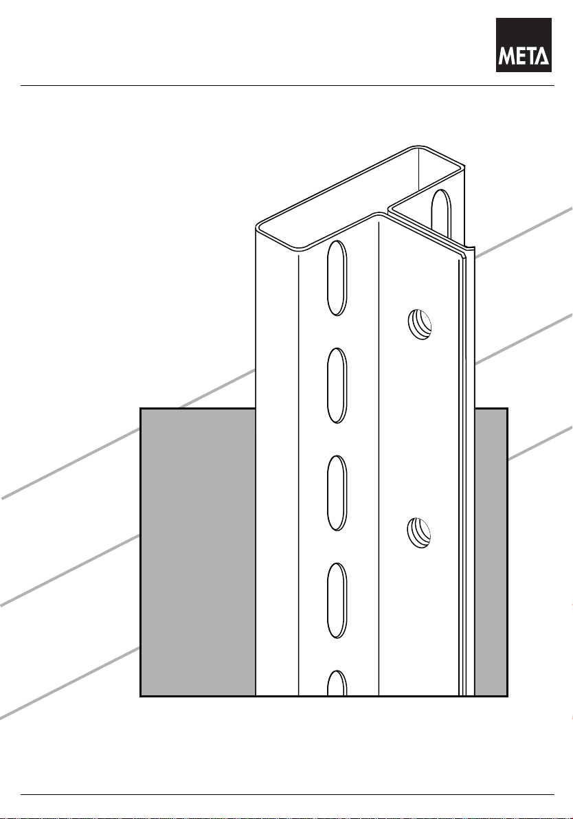
Das Lagersystem
AUFBAU-und BEDIENUNGSANLEITUNG
Stand 05.2009
Assembly and operating instructions
Instructions de montage et de service
95311
Zubehör
META-CLIP
Stand 05.2009
Steckregal
Page 2
Das Lagersystem
Inhaltsverzeichnis
Stand 05.2009
Index
Indice
Beschreibung Seite
Benötigtes Werkzeug 3
Wichtige Hinweis und Sicherheitsregeln für die Aufstellung 4
Fülleiste: Doppelregal 8
Abdeckkappe, Kunststoff 9
Sockelleiste, Gangbeschilderung 10
Zubehör für Eurolochwand 11
Steck-Schüttgutmulde, Steck-Schüttgutleiste 12
Trenngitter und Fachteiler 13
Drahtrückwand 14
Drahtseitenwand 15
Tiefenauflage 16
Boden M100 Verstärkungsunterzug für Boden M100 Reifenauflage 17
Vorsatzgitter und Fachteiler für Fachboden 18
Drahtkorb Drahtfachteiler Rohranbindung 19
Stufenholm Sicherungsstift A-Unterzug 20
U- und M-Trennbügel-Fachteiler Steckrohr-Fachteiler Fachteilerstab 21
Trageschiene / Warenträger 22
Bürosteckregal:
Fachteiler, verschiebbar 23
Pendelprofilanbindung Tiefenauflage 24 + 25
Endrahmen Seitenwand 26
Auszug Hängeregister 28 - 31
Büro-Compact Ausziehbarer Fachboden 32
Vorsatztüren 33
Einbau Rückwand 34
Einbau Türriegel 35
Einbau Stangenführung Türanschlag 36
Einbau Türflügel 37
Türschloss 38
Vorsatztüren Schubladen 39
Einbau Vorsatztüren 40
Einbau Schubladenblöcke 41 - 44
Schubladenblock Tür Theke 45
Kunststoffkastentypen, Tiefenteiler, Trennblech 46 - 47
Ausziehbarer Fachboden 48
Sichtblende - Beleuchtung 49
Vosatzbodenträger + Vorsatzboden 50 - 51
Vorsatzpult 52
Vorsatzleiste Prospekthalter A4 53
ACHTUNG: / CAUTION: / ATTENTION :
System-Teile für META-CLIP sind separat ausgeführt:
AUFBAU-und BEDIENUNGSANLEITUNG META-CLIP “System” Nr. 73566
System parts for META-CLIP are listed separately:
ASSEMBLY and OPERATING INSTRUCTIONS META-CLIP "System" No. 73566
Les éléments système pour META-CLIP sont présentés séparément:
INSTRUCTIONS DE MONTAGE ET D'UTILISATION META-CLIP "système". Numéro 73566
Technische Änderung vorbehalten.
Subject to technical changes
Sous réserve de modifications techniques
2
Page 3
Das Lagersystem
Benötigtes Werkzeug
Stand 05.2009
Tools required
Outils indispensables
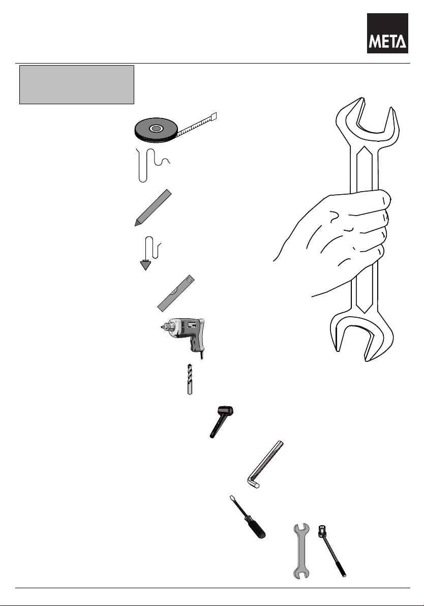
Benötigtes Werkzeug
Tools required
Outils indispensables
Maßband
Measuring tape
Mêtre
Schnur
Cord
Mêtre-ruban
Kreide
Chalk
Craie
Lot
Plumbline
Fil à plomp
Wasserwaage
Water level
Niveau à bulle d´air
Schlagbohrmaschine
Percussion drill
Perceuse à percussion
Schlagbohrer Ø 10 + Ø 6
Percussion drill bits Ø 10 + Ø 6
Foret à percussion Ø 10 + Ø 6
Kunststoff- oder Gummihammer
Plastic or rubber hammer
Marteau en plastique ou en caoutchouc
Innensechskant-Schlüssel SW 4
Spanner for hexagonal socket-headed screws
Clé mâle coudée pour vis à six pans creux
Schraubendreher
Screwdriver
Tournevis
Maul- und Steckschlüssel SW 10
Open- jawed and box spanners,sizes 10
Clè à fourche et clé à pipe ( à douille ), ouverture 10
3
Page 4
Das Lagersystem
Hinweise Sicherheitsregeln für die Aufstellung und Bedienung von
Stand 05.2009
META-Regalen
Lesen Sie vor dem Aufbau Ihrer META - Regale unbedingt die in
dieser Anleitung aufgeführten Informationen.
Bitte halten Sie sich bei dem Aufbau und bei der späteren
Nutzung exakt an die Angaben in dieser Anleitung, den
Hinweisen in unseren Auftragspapieren sowie den Belehrungen
durch unser Fachpersonal.
Die von META gelieferte Regalteile dürfen nur ihrem
Verwendungszweck entsprechend eingesetzt werden. Für
unsachgemäßen Einsatz, Nutzung oder Montage übernimmt
META keine Gewährleistung.
Alle Angaben in dieser Anleitung gelten nicht für Regale in
Außenaufstellung, bzw. Regale, die zusätzlich durch Wind,
Schnee, Erdbeben oder andere Zusatzlasten beaufschlagt sind.
In solchen Fällen ist eine individuelle Dimensionierung durch den
Hersteller erforderlich.
Durch Umbau, bzw. Neuaufstellung unserer Regale an einem
anderen Ort können sich die Bedingungen für die Nutzung und
Belastung ändern.
Bei Umbau der Regalanlage bzw. Unstimmigkeiten beim Aufbau,
sind META-Fachleute zu Rate zu ziehen.
Der Aufbau sowie der Umbau der Regale darf nur im
unbeladenen Zustand nach unseren beiliegenden Aufbau- und
Bedienungsanleitungen vorgenommen werden.
Die Beladung der Regale darf erst nach völligem
Montageabschluss vorgenommen werden.
Der Aufbau der Regale sollte durch mindestens 2 Personen
erfolgen. Gute Dienste leistet dabei ein hüfthoher Tisch, oder
zwei freistehende Böcke, auf denen die Bauteile zur Vormontage
aufgelegt werden können.
Beim Zusammenbau der Einzelteile darf keine rohe Gewalt durch
Einschlagen mit einem Metallhammer, oder durch Hebelstangen
angewendet werden. Verwenden Sie grundsätzlich einen
Gummihammer oder eine weiche Holzzwischenlage.
Um Personen- und Sachschäden abzuwenden, haben wir uns als
Hersteller von Regalanlagen den vom RAL anerkannten Güteund Prüfbestimmungen der RAL-RG 614 unterworfen.
Bei der Planung von Regalanlagen sind die "Richtlinien für
Lagereinrichtungen und -geräte BGR 234" des Hauptverbandes
der gewerblichen Berufsgenossenschaften, Stand 10/88, sowie
die einschlägigen Arbeitsstättenverordnungen verbindlich und die
allgemeinen Unfallverhütungsvorschriften zu beachten.
Von META werden die maximalen Stützlasten und
Flächenpressungen am Fußboden vorgegeben. Sie als Betreiber
müssen dafür Sorge tragen, dass diese Belastungen vom Boden
des Aufstellplatzes sicher aufgenommen werden können. Bei
fehlenden Angaben darf META von einer zulässigen
Fußbodenpressung von mindestens 50 Kg/cm² ausgehen.
Verkehrswege in Regaleinrichtungen sind mindestens 1,25m,
Nebengänge mindestens 0,75m breit auszulegen. Der
Sicherheitsabstand zu Fördermitteln muss mindestens 0,50m auf
jeder Seite betragen.
Die angegebenen, maximal möglichen Fach- und Feldlasten
dürfen nicht überschritten werden.
Regale mit einer Fachlast von mehr als 200 Kg oder einer
Feldlast von mehr als 1.000Kg müssen mit einem Typenschild
gekennzeichnet sein. Typenschildangaben: Hersteller, Baujahr
oder Kommissioniernummer, zulässige Fach- und Feldlasten.
Das mitgelieferte Typenschild ist deutlich sichtbar anzubringen.
Bei korrosionsaktiven Industrieböden (z.B. Magnesitböden) muss
eine Isolierung der Stützenfußbereiche vorgesehen werden. Die
Gebrauchsanleitung der Fußbodenhersteller ist verbindlich zu
beachten.
Regalanlagen dürfen nur nach den ihrer Bestimmung zugrunde
liegenden Maßgaben belastet werden. Die Beladung der Regale
sollte gleichmäßig vorgenommen werden, da die statische
Auslegung auf der Annahme einer gleichmäßig verteilten
Flächenbelastung beruht. Punktförmige Stoßlasten und
Schiebelasten sind daher grundsätzlich zu vermeiden.
Regalrahmen und -fächer, insbesondere Fachböden dürfen nicht
von Personen betreten werden.
Beschädigte und verformte tragende Bauteile einer Regalanlage
müssen umgehend ausgetauscht werden, da die Belastbarkeit
nur im einwandfreien Zustand von META garantiert wird.
Gemäß §10 Prüfung der Arbeitsmittel des
Gerätes- und Produktsicherheitsgesetzes unterliegen Regale der
Prüfpflicht.
Wir empfehlen:
- monatliche Prüfung auf Beschädigung durch den Betreiber
und
- jährliche Inspektion durch den Hersteller
Jährliche Inspektionspflicht für Lagereinrichtungen
Der Arbeitgeber ist dazu verpflichtet, sämtliche
Lagereinrichtungen - d.h. elektrisch angetriebene sowie
statische Regale - systematisch und regelmäßig zu
inspizieren. Wenn vom Regalhersteller aufgrund der
Konstruktion oder der Einsatzbedingungen keine
verschärften Inspektionen gefordert werden, sind die
Regelungen der BGR 234 sowie der Normentwürfe DIN
EN 15512, DIN EN 15620, DIN EN 15629 und im
Besonderen der DIN EN 15635 einzuhalten. Laut der
Betriebssicherheitsverordnung (BetrSichV) trägt der
Arbeitgeber die Verantwortung für die Sicherheit seiner
Lagereinrichtung. Regale müssen somit mindestens alle
12 Monate durch einen Experten inspiziert werden.
META bietet diese Experteninspektion durch einen
verbandsgeprüften Regalinspektor an. Zu näheren
Informationen: www.regalinspektion.de
Auf verzinkten Regalböden oder Paneelen dürfen nicht
unmittelbar Lebensmittel gelagert werden.
Die maximal zulässigen Bodenunebenheiten am Aufstellort sind
der DIN 18202, Tabelle 3, Zeile 3 zu entnehmen.
4
Page 5
Das Lagersystem
Instructions Safety Rules for the mounting and handling of META
Stand 05.2009
shelves
Safety Rules for the mounting and handling of META shelves
Please read the information presented in this guideline thoroughly
before you start mounting your META shelves. Please follow in
the course of mounting and during the utilization of the shelves
exactly the advice given in these guide-lines and follow the
instructions in our order documents as well as the advice given by
our technical experts.
The shelf components supplied by META are allowed to be
utilized only in the framework of the technical purpose intended.
META does not accept any warranty for improper handling,
utilization or mounting.
All details in these instructions do not apply to outdoor racks or
racks that are additionally subject to stress by wind, snow,
earthquakes or other additional loads. In such cases, individual
dimensioning by the manufacturer is essential.
It is possible that the conditions for the utilization of the shelves
are changed, when they are placed at a different location, when
they are altered in their construction or when they are newly
erected.
In case the construction of the shelves is altered or when
difficulties are encountered during erection, you are strongly
advised to ask for META experts to assist you.
Mounting and erection work is allowed to be carried out only when
the shelves are empty, according to our Mounting and Handling
Instruction Sheets attached.
The shelves are permitted to be loaded only after the mounting
work has completely been completed.
For the mounting of the shelves, a minimum of two persons is
required. Very useful in this connection is a table with a height up
to the hips, or two free standing horses, on which the individual
components can be placed for the preliminary mounting.
When joining the various components, it is not allowed to use
great force to forcibly insert by means of a metal hammer or by
using a lever. On principle, use only a rubber hammer or a soft
wooden intermediary layer.
We, as the manufacturers of shelf constructions, have submitted
and dedicated ourselves to the Quality and Testing Regulations
RAL-RG 614, recognized by the RAL Institute, in order to prevent
injuries of persons and material damage.
In the course of planning shelf installations, the "Guidelines for
Storage Installations and devices BGR 234" of the Main
Association of the industrial trade organizations, status 10/88, as
well as the relevant regulations governing the prevailing
conditions at the workplace are binding, and the general
regulations for the prevention of accidents must be adhered to.
META states the maximum supporting loads and the pressures
allowed to be exerted on the surfaces of the areas at the ground.
The customer and user must ensure that the bearing capacity of
the ground at the place of mounting can safely withstand these
loads. Unless specific details are made to the contrary, META
assumes that the minimum permissible floor pressure is 50 kg/
cm².
The minimum width for traffic aisles in shelf constructions is 1.25
m, the minimum width of sub-aisles is 0.75 m. The minimum
safety distance between the means of transportation and the
shelves must be 0.50 m on either side.
The maximum possible shelf and field loads as stated are not
allowed to be exceeded.
Shelves with a shelf load of more than 200 kg or a field load of
more than 1000 kg must be equipped with a name plate.
The necessary details on this name plate are as follows:
Manufacturer, year of construction or number of commissioning,
admissible shelf and field loads. The name plate supplied must be
attached at a conspicuous place of the construction.
In the case of corrosive active industrial floors (e.g. magnesite
floors), an insulation of the support base areas must be provided
for. The instructions for use, issued by the floor manufacturers,
must be strictly observed.
Shelf constructions are allowed to be loaded only in strict
compliance with the purpose intended on the basis of the details
specified. Loading of the shelves should be carried out in a
uniform manner, because the static design is based on
assumption that the area loading will be effected uniformly.
Impact loads on certain points only and sliding loads must, on
principle, be avoided.
Persons are not allowed to stand or walk on the shelf frames and
shelf boards.
Bearing components that are damaged or deformed out of shape
must be replaced without delay because the nominal load
capacity is warranted by META on the condition that the complete
construction is in perfect shape.
According to §10 Testing of Equipment of the Appliance and
Product Safety Act, the testing of racks is obligatory.
We recommend:
- monthly inspection for damage performed by the plant operator
and
- yearly inspection by the manufacturer
Mandatory annual inspections for warehouse equipment
The employer is obligated to inspect all of its warehouse
equipment - including all electric-powered vehicles as well as
static shelving - systematically and at regular intervals. Providing
that the racking manufacturer does not stipulate that additional
inspections are to be made due to the specific design of the
racking or its conditions of use, the following regulations must be
met: BGR 234 (stipulated by the German employer's liability
insurance association) as well as Draft Standards DIN EN 15512,
DIN EN 15620, DIN EN 15629 and, in particular, DIN EN 15635.
According to the terms of the German Ordinance on Industrial
Safety and Health (BetrSichV), the Employer is responsible for
the safety of its racking equipment. For this reason, racking
systems must be inspected by an expert every 12 months. META
offers an expert inspection service conducted by an Associationcertified racking inspection body. For more information, please
go to www.regalinspektion.de
Food is not allowed to be placed directly on galvanized shelves or
panels. For the maximum permissible deviations from levelness
conditions at the place of mounting, see DIN 18202, Table 3, line
3.
.
5
Page 6
Das Lagersystem
Indications et règles de sécurité pour le dressage et l'utilisation des
Stand 05.2009
rayonnages META
Avant de procéder au dressage de vos rayonnages META,
veuillez lire impérativement les informations et "règles de
sécurité" fournies dans les présentes instructions. Veuillez
également, aussi bien lors du dressage que l'utilisation ultérieure
de vos rayonnages, vous conformer exactement aux informations
fournies dans les présentes instructions, aux indications figurant
dans nos documents de commande ainsi qu'aux enseignements
fournis par notre personnel technique.
Les éléments de rayonnage livrés par META ne doivent être
utilisés que conformément à leur destination. META décline toute
responsabilité pour tous les dommages qui résulteraient d'une
exploitation, d'une utilisation ou d'un montage incorrects du
rayonnage.
Toutes les indications fournies dans les présentes instructions ne
s'appliquent pas aux rayonnages implantés à l'extérieur ou à ceux
qui sont soumis à la charge supplémentaire du vent, de la neige,
d'un tremblement de terre ou à toute autre charge
supplémentaire. Dans les cas suscités, un dimensionnement
individuel par les soins du constructeur sera nécessaire.
La reconstruction et le nouveau dressage de nos rayonnages sur
un autre site sont susceptibles d'entraîner la modification des
conditions d'utilisation et de charge.
Faites appel à des spécialistes de META à toute reconstruction
de l'installation à rayonnages ou en cas d'irrégularités lors du
dressage.
Le dressage et la reconstruction des rayonnages ne doivent être
effectués que lorsque ces derniers sans vides, conformément à
nos instructions de dressage et d'utilisation ci-jointes.
Le chargement des rayonnages ne doit être effectué qu'après la
fin totale des travaux de montage.
Le dressage des rayonnages doit être effectué par deux
personnes au moins. De précieux services vous seront fournis
dans ce contexte par une table présentant la hauteur la hauteur
de la hanche ou deux chevalets librement implantés, sur lesquels
vous pourrez poser les éléments pour le montage préliminaire.
Au moment de l'assemblage des différents éléments, il ne vous
est pas permis d'exercer une violence brute, par exemple par des
frappes à l'aide d'un marteau métallique ou par l'utilisation d'une
barre de relevage utilisée comme bras de levier. D'une manière
générale, utilisez une massette en caoutchouc ou une lame
intercalaire en bois tendre.
Dans le but de vous éviter les dégâts humains et matériels, nous
nous sommes conformé comme constructeur d'installation de
rayonnages aux dispositions de qualité et d'essai RAL-RG 614,
reconnues par le RAL.
L'étude des installations de rayonnage est soumise
obligatoirement aux "directives relatives aux installations et
appareils de stockage BGR 234" du Regroupement principal des
unions professionnelles industrielles, situation 10/88 ; conformezvous également aux ordonnances afférentes relatives aux lieux
du travail et aux dispositions générales relatives à la prévention
des accidents de travail.
La société META vous indique les valeurs maximales pour la
charge d'appui verticale et la pression superficielle au plancher.
En votre qualité d'exploitant du rayonnage, vous êtes tenus de
prendre les mesures nécessaires afin que ces charges exercées
au sol du lieu de dressage puissent être supportées sûrement.
Dans le cas de l'absence d'information, la société META admettra
une pression superficielle minimale sur le plancher de 50 Kg/cm2.
Au sein des installations de rayonnages, vous devez
dimensionner les voies de circulation à une largeur minimale de
1,25 m et de 0,75 m pour les passages secondaires. La distance
de sécurité minimale vis-à-vis des engins de transport doit être de
0,50 m sur les deux côtés.
Il ne vous est pas permis de dépasser les charges maximales
possibles par casier et par niveau, telles qu'elles sont indiquées.
Les rayonnages dotés d'une charge par niveau supérieur à 200
kg ou une charge par casier supérieure à 1.000 kg doivent
impérativement être repérés par une plaque signalétique.
Indications sur la plaque signalétique : Constructeur, année de
construction ou numéro de commission, charges par casier et par
niveau autorisées. La plaque signalétique fournie avec le
rayonnage doit être montée à un endroit bien visible.
Sur les sols industriels favorisant la corrosion (par exemple les
planchers magnésiens), il sera nécessaire de prévoir un
isolement des zones de pieds des appuis. Les instructions du
fabricant du plancher doivent être respectées obligatoirement.
Les installations de rayonnages ne doivent être soumises aux
charges que conformément aux prescriptions conformes à leur
destination. Le chargement des rayonnages doit être effectué
uniformément, car la conception statique se fonde sur la
présomption d'une charge superficielle uniformément répartie.
Par conséquent, évitez en général les charges par à-coups et les
charges coulissantes ponctuelles.
Il n'est pas permis aux personnes d'accéder aux cadres et aux
casiers des rayonnages, notamment aux fonds de casier.
Remplacez impérativement et immédiatement les pièces
porteuses endommagées et déformées d'une installation de
rayonnages, car la capacité de charge ne vous est garantie par
META que dans l'état technique impeccable de ces éléments.
Conformément à l'article 10 portant sur l'examen des moyens de
travail de la Loi sur la sécurité des appareils et des produits, les
rayonnages sont soumis à l'obligation de contrôle.
Nous vous recommandons :
-un contrôle mensuel de la présence éventuelle de dommages
par l'exploitant
et -une inspection annuelle par le constructeur
Obligation d'inspection annuelle pour les installations de
rayonnages
L'employeur est tenu d'effectuer une inspection systématique et
régulière de toutes les installations de rayonnages - c'est-à-dire
les rayonnages à commande électrique et statiques. Si le
constructeur du rayonnage n'exige pas d'inspections plus
rigoureuses en raison de la construction du rayonnage ou de ses
conditions d'exploitation, les inspections doivent se conformer
aux règlements BGR 234 ainsi qu'aux projets de normes DIN EN
15512, DIN EN 15620, DIN EN 15629 et, particulièrement, à la
norme DIN EN 15635. En vertu de l'ordonnance allemande
relative à la sécurité dans les entreprises (BetrSichV),
l'employeur est responsable de la sécurité de ses rayonnages.
Les rayonnages doivent ainsi faire l'objet d'une inspection par un
expert au moins une fois tous les 12 mois. META propose ces
inspections d'expert par les soins d'un inspecteur de rayonnage
agréé par le regroupement professionnel. Pour de plus amples
informations : www.regalinspektion.de.
Il ne vous est pas permis de stocker des aliments directement sur les
fonds de casier zingués ou sur les panneaux de lambris.
Les inégalités de sol maximales au lieu de dressage du rayonnage
vous sont indiquées par la norme DIN 18202, tableau 3, ligne 3.
6
Page 7

Das Lagersystem
Notizen
Stand 05.2009
Notes
Notes
7
Page 8
Das Lagersystem
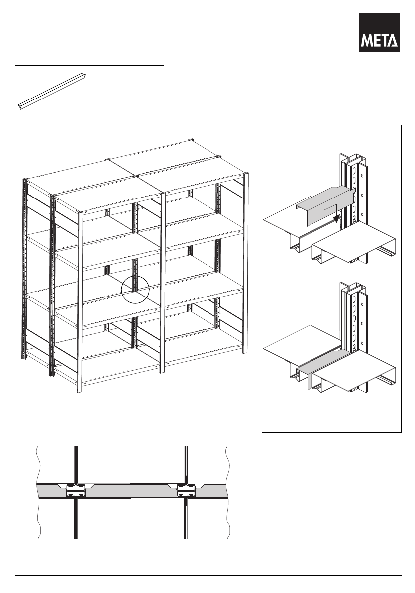
Fülleiste : Doppelregal
Stand 05.2009
Filler strip : double rack
Rebord de remplissage : rayons double
Fülleiste
Filler strip
Rebord de remplissage
A
A
8
Page 9

Das Lagersystem
Abdeckkappe , Kunststoff
Stand 05.2009
Covering cap , plastic
Couverture , matiére plastique
A
B
B
Abdeckkappe , Kunststoff
Einfachregal
Covering cap , plastic
Single rack
Couverture , matiére plastique
Rayons simple
Abdeckkappe , Kunststoff
Doppelregal
Covering cap , plastic
Double rack
Couverture , matiére plastique
Rayons double
A
Profilklammer für Doppelregal
Profile clip for double rack
Agrafe profil pour rayons doubles
9
Page 10
Das Lagersystem
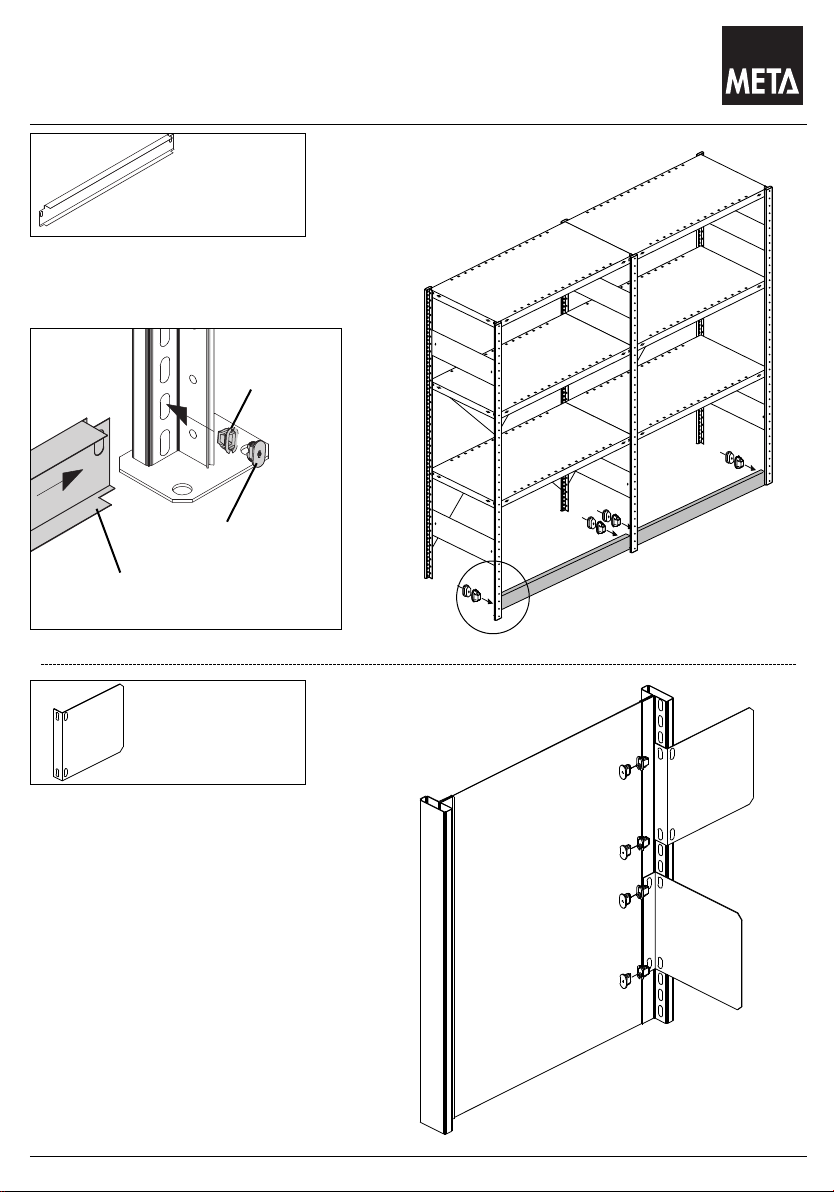
Sockelleiste , Gangbeschilderung
Stand 05.2009
Base strip, Aisle sign
Plinthe, Pancarte de rangée de rayonnage
Sockelleiste
Base strip
Plinthe
A
Spannhülse
Spreizkern
Sockelleiste
A
Gangbeschilderung
Aisle sign
Pancarte de rangée de
rayonnage
10
Page 11
Das Lagersystem
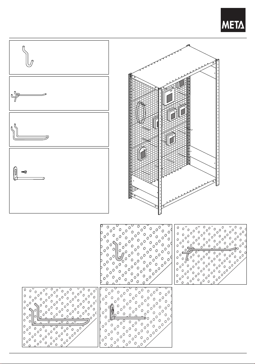
Zubehör für Eurolochwand
Stand 05.2009
Accessories for Clip Euro standard perforated panel
Accessoires pour paroi perforée Euro
A
B
C
D
Lochplattenhaken
hooks for perforated panel
Crochets pour plaques
perforées
Aufhängehaken
Suspension hooks
Crochets de
suspension
Lochplattendoppelhaken
double hooks for perforated
panel
Crochets doubles pour
plaques perforées
Lochplattenhaken zum
Aufschrauben mit
Blechschraube B 5,5x13
hooks for perforated panel
screwing with sheet
metal screw B 5,5 x 13
Crochets pour plaques
perforées pour vissage
avec des vis en pressetole B 5,5 x 13
C
11
D
A
B
Page 12
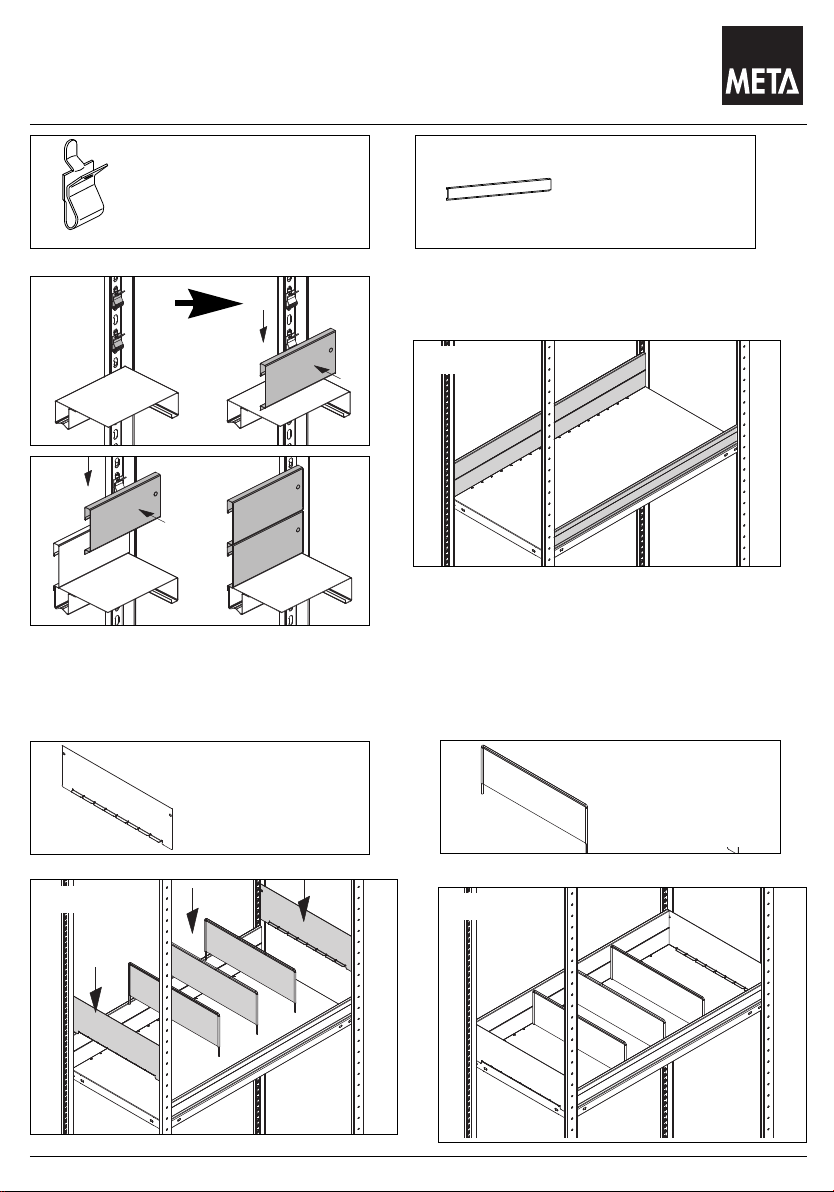
Das Lagersystem
Steck-Schüttgutleiste und Steck-Schüttgutmulde
Stand 05.2009
A
B
1.
5.
Abdeckbodenträger 40 Gelb
Top shelf clip 40 yellow
Support se fond de
recouvrement 40 jaune
A
3.
2.
4.
B
A + B
Schüttgutleiste
Bulk retaining strip
Rebord pour produits
en vrac
C
C + D
Seitenblech
Side panel
Panneau latéral
12
D
C + D
Fachteiler
Shelf dividers
Eléments de séparationpour casiers
Page 13
Das Lagersystem
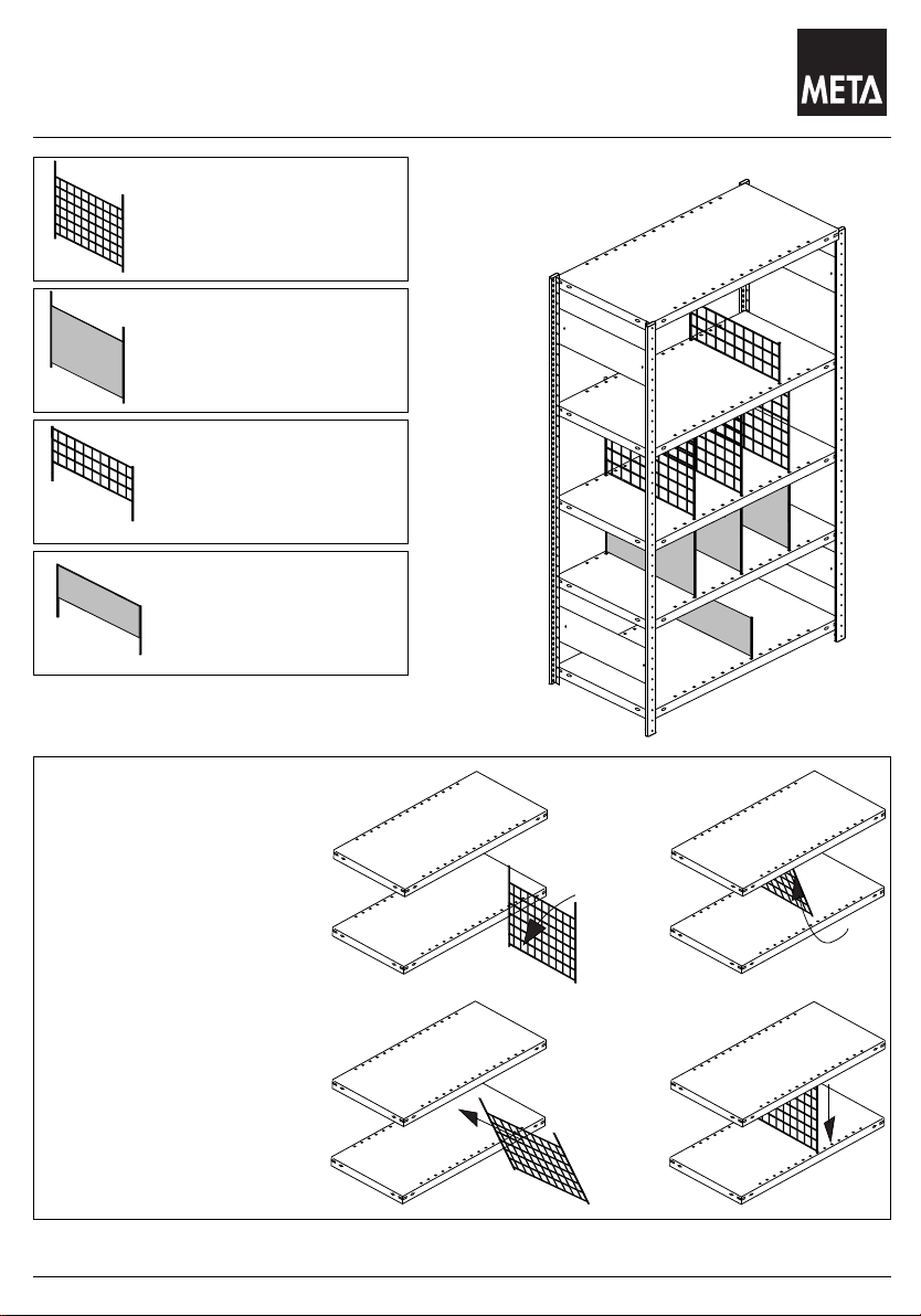
Trenngitter und Fachteiler
Stand 05.2009
Separating grille and shelf dividers
Grilles de séparation et éléments de séparation pour casiers
Trenngitter
Separating grille
Grilles de séparation
Fachteiler
Shelf dividers
Eléments de séparationpour casiers
Trenngitter
freistehend
Free-standing separating grille
Grille de séparating non
soutenue
Fachteiler freistehend
Free-standing separator
Elément de séparation
pour casier non soutenu
Die Abbildungen zeigen den Einbau der
Trenngitter. Bei Fachteilern in gleicher
Weise verfahren.
The illustrations show
how to fit the separating
grills. Proceed in exactly
the same way for the shelf
dividers.
Les illustrations montrent
le montage des grilles de
séparation. Procéder de
manière iden tique por les
éléments de séparation
pour casiers.
1.
2.
3.
4.
13
Page 14
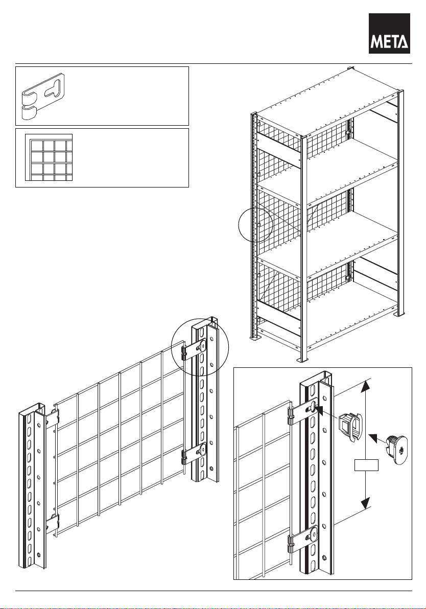
Das Lagersystem
Drahtrückwand
Stand 05.2009
Wire mehs rear wall
Paroi arrière en fil métallique
Universal
Drahtwandhalter
Universal wire mesh
wall clamp
Support universel pour
paroi en fil métallique
Drahtwand
Wire wall
Paroi en fil métallique
A
A
A
≤ 500
14
Page 15
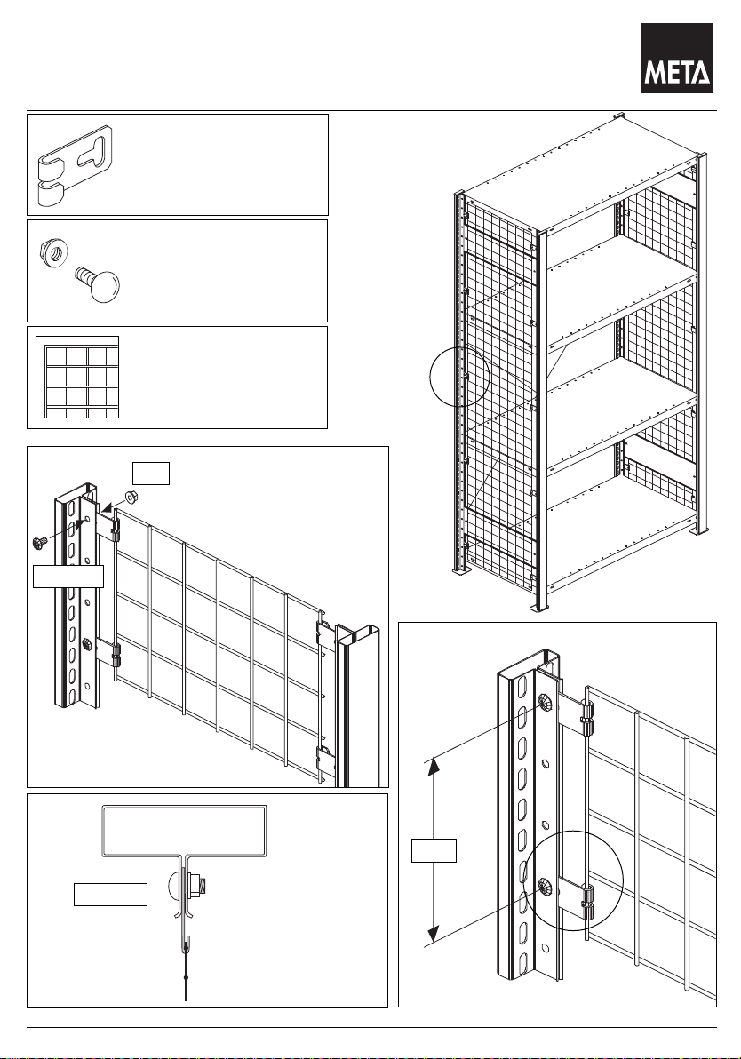
Das Lagersystem
Drahtseitenwand
Stand 05.2009
Wire side wall
Paroi latérale en fil métallique
Universal Drahtwandhalter
Universal wire wall clamp
Support universel pour
paroi en fil métallique
Flachrundschraube
M6 x 10 mit Mutter
Round-head bold
M6 x 10 with nut
Boulon à tête bombée
M 6 x 10 avec écrou
Drahtwand
Wire wall
Paroi en fil métallique
A
A
M6 x 10
A
M6 x 10
M6
≤ 500
A
15
Page 16
Das Lagersystem
300 300
400 400
500 500
600 600
Tmm
Tiefenauflage
Stand 05.2009
Depth support
Support en profondeur
1
Tiefenauflage
Depth support
Support en profondeur
T
2
1
Tiefenauflage 20°
Depth support 20°
Support en profondeur 20°
2
2
20°
1
1
1.
2
1.
2.
4.
3.
2.
3.
4.
16
Page 17
Das Lagersystem
Boden M 100 , Verstärkungsunterzug für Boden M 100,
Stand 05.2009
Reifenauflage
M 100 shelf , Reinforcing underbeam for M 100 , Tyre support
Fond M 100 , Solive de renforcement pour fond M 100, Support pour pneus
1
Boden M 100
M 100 shelf
Fond M 100
2
Verstärkungsunterzug
für Boden M 100
Reinforcing beam
for M 100 shelf
Solive de renforcement
pour fond M 100
3
Reifenauflage
Tyre support
Support pour pneus
Längsriegelsicherung bei Reifenregal
Longitudinal for tyre rack
Dispositif de sécurité de poutre
longitudinale pour rayon à pneus
Sichern mit Blechschraube 4.8 x 13
Locked with sheet metal
screw 4.8 x 13
Dispositif de sécurité
avec vis à tôle
hexagonale 4.8 x 13
A
A
A
A
1
100
Gleichmäßig
verteilte Last
Evenly distributed load
Charge réguliérement
réparatie
2
200
Gleichmäßig
verteilte Last
Evenly distributed load
Charge réguliérement
réparatie
A
A
3
pro Paar
A
A
200
Gleichmäßig
verteilte Last
Evenly distributed load
Charge réguliérement
réparatie
17
Page 18

Das Lagersystem
Vorsatzgitter und Fachteiler für Fachböden
Stand 05.2009
1
2
Vorsatzgitter
Wire stoppers
Grille avant
Fachteiler freistehend
Free-standing separator
Elément de séparation
pour casier non soutenu
1.
A
2.
1
1
1.
Detail “A”
2
1
1
2
2
1
18
Page 19

Das Lagersystem
Drahtkorb / Drahtfachteiler / Rohranbindung
Stand 05.2009
Wire basket / Wire separator / Tube connection
Panier en fil métallique / Elément de séparation pour casier en fil
métallique / Raccord pour tube
1
2
3
4
5
Drahtkorb,
Wangenhöhe 120 / 120
Wire basket, Sidewall
height 120 / 120
Panier en fil metallique,
Hauteur de face 120 / 120
Drahtkorb,
Wangenhöhe 120 / 60
Wire basket, Sidewall
height 120 / 60
Panier en fil metallique,
Hauteur de face 120 / 60
Drahtfachteiler
120 / 120 für Drahtkorb
Wire separator 120 /120
for basket
Elément de séparation pour
casier en fil metallique
120 / 120 pour panier en fil
metallique
Drahtfachteiler
120 / 60 für Drahtkorb
Wire separator 120 /60
for basket
Elément de séparation pour
casier en fil metallique
120 / 60 pour panier en fil
metallique
Rohranbindung
Tube connection
Raccord pour tube
120 gvL.
120 gvL.
70 gvL.
1
2
5
M6 x 35
DIN 934
4
3
gvL. = gleichmäßig
gvL. = Evenly distri-
gvL. = Charge régulié-
M6
DIN 934
verteilte Last
buted load
rement réparatie
19
Page 20

Das Lagersystem
Stufenholm / Sicherungsstift / A-Unterzug / Spanplatte
LT
mm mm
kg
Stck Stck
1000
400 1 1
1300
800
400 1 1
2000
400 2 1
Stand 05.2009
Stepped post / Locking pin / A-bearer / Particle board
Montant à paliers / Goupille de sécurité / A-renforcement /
Panneau de particules
1
Stufenholm
Stepped post
Montant à paliers
2
Sichrungsstift
Locking pin
Goupille de sécurité
3
A-Unterzug
A-Bearer
A-Renforcement
T
4
Spanplatte 19mm
Particle board 19mm
Panneau de particules
19mm
L
1
4
Belastungen
Load capacities
Charges
L
1
3
1 + 2
3
20
Page 21

Das Lagersystem
M- und U- Trennbügel-Fachteiler; Steckrohr-Fachteiler;
H
T
mm mm
250
500 800
750
Stand 05.2009
Fachteiler
M- shaped and U - shaped bracket shelf divider
Elément de séparation pour casier à étrier de séparation en M + U
1
2
3
4
1
M-Trennbügel-Fachteiler
M-shaped bracket shelf
divider
Elément de séparation pour
casier à étrier de séparation
en M
U-Trennbügel-Fachteiler
U-shaped bracket shelf
divider
Elément de séparation pour
casier à étrier de séparation
en U
Steckrohr-Fachteiler
Slot-in tube divider
Elément de séparation
pour
casier en tubes à emboîter
Fachteilerstab
Shelf dividing rod
Barre d’élément de séparation pour casier
T
2
1
3
2
2
4
T
H
H
4
3
21
Page 22

Das Lagersystem
Trageschiene / Warenträger
Stand 05.2009
supporting bar / commodity-supporting bar
barre de support / barre porte-charge
1
Trageschiene
supporting bar
barre de support
2
2
3
Aufsteckhalter
creel mount
appui relevable
Warenträger
commodity-supporting
bar
barre porte-charge
Weitere Warenträger
auf Anfrage
Additional commodity-supporting
bars upon request
Des barres porte-charge additionnelles sur demande
1
3
1
3
1
1.
2.
2
3.
22
Page 23

Das Lagersystem
Bürosteckregal: Fachteiler, verschiebbar
Stand 05.2009
Quick-fit office shelving: Shelf seperator, sliding
Rayons enfichables de bureau: Séparateur de fond, coulissant
1
Fachteiler
verschiebbar
Shelf separator
sliding
Séparateur de fond
coulissant
1
1.
2.
3.
23
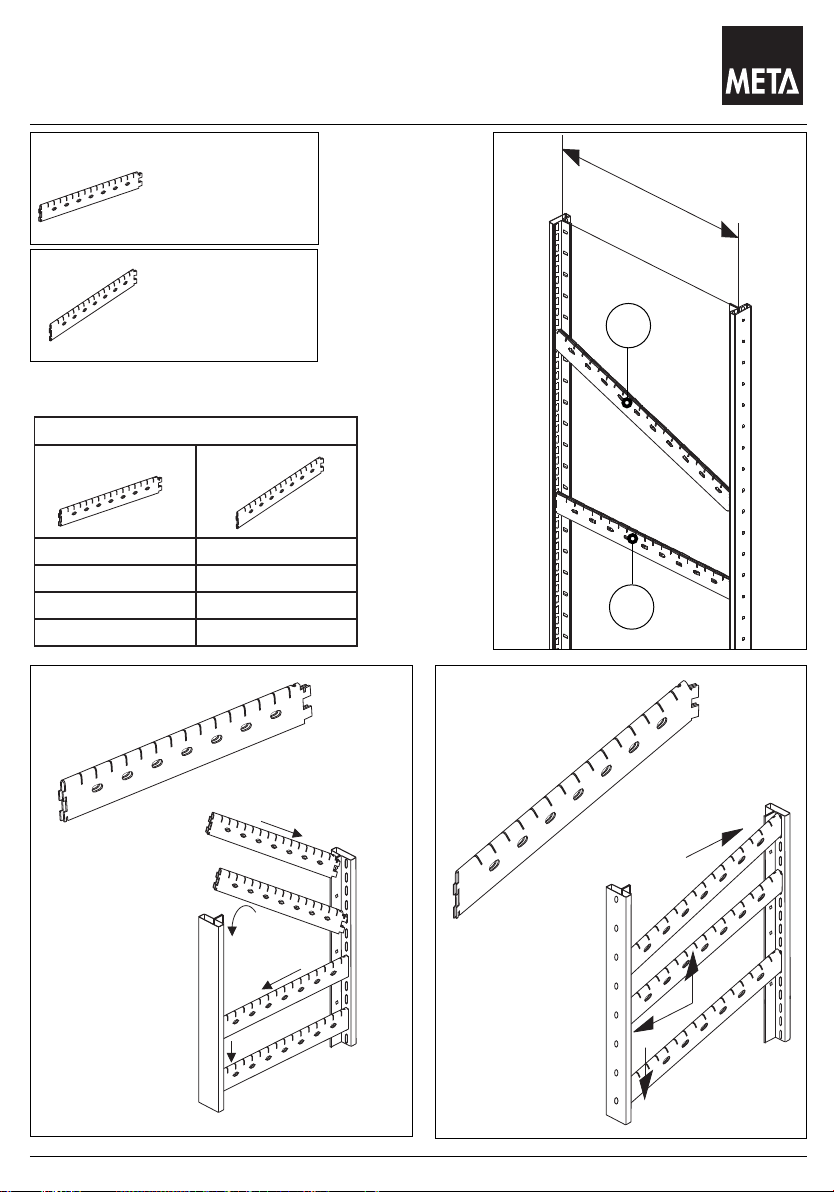
Page 24

Das Lagersystem
Bürosteckregal : Pendelprofilanbindung / Tiefenauflage
>300mm
Stand 05.2009
Quick-fit office shelving : Suspended profile connection / Depth support
Rayons enfichables de bureau : Raccord pour profil de suspension /
Support en profondeur
1
Tiefenauflage
Depth support
Support en
profondeur
2
Pendelprofilanbindung
Suspended profile
connection
Raccord pour profil
de suspension
1.
2.
3.
4.
M6
M6 x 15
24
max. 50kg
gleichmäßig verteilte Last
max. 50 kg evenly distributed load
max. 50 kg de charge uniformément repartie
Page 25

Das Lagersystem
Bürosteckregal : Pendelprofilanbindung
300
2200
1
000
300250
300
300 300
50
300
300
1
000
325325
325300
1850
100
325
300
Stand 05.2009
Quick-fit office shelving : Suspended profile connection
Rayons enfichables de bureau : Raccord pour profil de suspension
25
Page 26

Das Lagersystem
Bürosteckregal : Endrahmen Seitenwand
1850 2 922
8
(2+2 x 2)
2200 2 1097
8
(2+2 x 2)
2550 2 1272
8
(2+2 x 2)
Stand 05.2009
Quick - fit office shelving : End frame side sheet
Rayons enfichables de bureau : Echelle de rive paroi latéral
Endrahmen
Seitenwand
End frame side sheet
Echelle de rive paroi
latéral
Hmm S h1mm S
h1
H
h 1
A
26
A
Page 27

Das Lagersystem
Notizen
Stand 05.2009
Notes
Notes
27
Page 28

Das Lagersystem
³ 275 mm
300
Auszug Hängeregister
Stand 05.2009
Extending hanging file module
Régistre suspendu extensible
Verwendung nur bei Regaltiefe 300 mm
Only for shelf depth 300 mm
Seulement pour profondeur de rayon 300 mm
A
A
2.
1.
M 6x10
3. 4.
28
5.
40
Page 29

Das Lagersystem
600
Auszug Hängeregister
=
=
Stand 05.2009
Extending hanging file module
Régistre suspendu extensible
Verwendung nur bei Regaltiefe 600 mm
Only for shelf depth 600 mm
Seulement pour profondeur de rayon 600 mm
≥ 275
1.
M 6x10
A
2.
3.
4.
5.
40
40
29
Page 30

Das Lagersystem
Auszug Hängeregisterregal Tiefe 300mm
Stand 05.2009
Extending hanging file module depth 300mm
Régistre suspendu extensible grave 300mm
40
40
30
Page 31

Das Lagersystem
Auszug Hängeregisterregal Tiefe 600mm
Stand 05.2009
Extending hanging file module depth 600mm
Régistre suspendu extensible grave 600mm
40
LR=
Längsriegel
Longitudinal crossbar
Poutre longitudinale
40
40
40
31
Page 32

Das Lagersystem
Büro - Compact: Ausziehbarer Fachboden
=
=
Stand 05.2009
Office - Compact: Pull out shelf
Bureau - Compact: Télsecopique à rallonage fond
1.
M 6x10
40
2.
40
40
1.
3.
4.
M 6x10
5.
A.
B.
32
Page 33

Das Lagersystem
Büro - Compact Vorsatztüren
H
L
mm mm
1850
750
1000
1250
H
L
mm mm
750
1000
1250
2200
H
L
mm mm
750
1000
1250
2550
Stand 05.2009
Clip - doors
portes clip
Vorsatztüren H =1850 mm
Clip - doors H = 1850 mm
Clip - porters H = 1850 mm
H
L
Vorsatztüren H =2200 mm
Clip - doors H = 2200 mm
Clip - porters H = 2200 mm
H
mögliche Varianten
possible variants
variantes possibles
mögliche Varianten
possible variants
variantes possibles
H
L
mögliche Varianten
Vorsatztüren H = 2550 mm
Clip - doors H = 2550 mm
Clip - porters H = 2550 mm
L
possible variants
variantes possibles
33
Page 34

Das Lagersystem
Hh1 h2 h3
mm mm
1850 25 1 2 12
2200 25 3 1 16
2550 25 5 20
Compact Vorsatztüren : Einbau Rückwände
Stand 05.2009
Compact clip doors : mounting of rear panels
Compact portes clip : montage panneaux arrières
C
2200
C
1850
h3
B
C
2550
h2
h2
h3
h2
h2
H
h3
h2
H
H
A
h2
h2
A
h2
h2
A
h1
h1
C
B
h1
A
H
H=500
H
H=650
34
Page 35

Das Lagersystem
Compact Vorsatztüren : Einbau Türriegel 25
Stand 05.2009
Compact clip doors : mounting of door bar 25
Compact portes clip : montage barre de porte 25
Türriegel 25
Door bar 25
Barre de porte 25
2550
25
1844
A
1850
750
1000
1250
2200
25
1725
2194
69
A
25
750
1000
1250
25
325
25
1725
2544
69
25
750
1000
1250
Türriegel 25
Door bar 25
Barre de porte 25
675
25
1725
69
25
bei Türriegel 25 Fachbodenträger nur hinten
for door bar 25, shelf clip at the rear
only
pour barre de porte 25 , support pour
fond du case uniquement à l’arrière
Sockelleiste
Base strip
Plinthe
Zusätzlicher Einbau einer Sockelleiste
Supplementary mounting of a base strip
Montage supplémentaire d’une plinthe
35
Page 36

Das Lagersystem
Compact Vorsatztüren : Einb. Stangenführung / Türanschlag
Stand 05.2009
Compact clip doors : mounting of bar guide way / door stop
Compact portes clip : montage guidage à tige / arrête-porte
A
Stangenführung
bar guide way
guidage à tige
Türanschlag
door stop
arrête-porte
B
A
B
C
C
36
Page 37

Das Lagersystem
Typ
H
mm
H1
mm
1 322 348
2 672 698
5 1722 1748
Compact Vorsatztüren : Einbau Türflügel
Stand 05.2009
Compact clip doors : mounting of doors leafs
Compact portes clip : montage vantails de porte
Scharnierstange
hinge bar
tige articulée
Zuerst untere Vorsatztür einsetzen.
Insert lower clip door first.
Placer d’abord la porte clip inférieure.
1.
1.
3.
5.
2.
H
4.
H1
3.
H
5.
2.
4.
37
Page 38

Das Lagersystem
Compact Vorsatztüren : Einbau Türschloß
Stand 05.2009
Compact clip doors : mounting of door lock
Compact portes clip : montage serrure de porte
Türschloß
door lock
serrure de porte
1
3
2
4
Aus Sicherheitsgründen müssen Regale mit einem Höhen - Tiefenverhältnis ≥ 5 : 1 ,
sowie grundsätzlich beim Einsatz von Türen gegen Kippen gesichert werden.
For safety reasons , it is essential to anchor racks with a height-to-depth ratio of ≥ 5 : 1 to prevent them toppling
over. Units fitted with doors must always be anchored irrespective of height-to-depth ratio.
Pour des raisons de sécurité , les rayons done le rapport hauteur / profondeur est ≥ 5 : 1 doivent étre sécurisés
contre un basculement, de méme que systématiquement lors de l’utilisation de portes.
38
Page 39

Das Lagersystem
58
58
73
Vorsatztüren / Schubladen
Stand 05.2009
Clip - doors / Drawer
Clip - porters /Tiroir
Türriegel :
oben / unten
Door bar :
top / bottom
Barre de porte :
du haut / en bas
Türriegel:
mitte
Door bar:
centre
Barre de porte:
centre
Vorsatztür
Clip-doors
Clip-porters
1= Türriegel oben, top door bar, Barre de porte du haut
2= Türriegel mitte, centre door bar, Barre de porte centre
3= Türriegel unten, bottom door bar, Barre de porte en bas
4= 1 / 1 Tür , 1 / 1 door , 1 / 1 porte
5= 1 / 2 Tür , 1 / 2 door , 1 / 2 porte
6= 1 / 4 Tür , 1 / 4 door , 1 / 4 porte
7= Schublade 100 , Drawer 100 , Tiroir 100
8= Schublade 200 , Drawer 200 , Tiroir 200
9= Sockelleiste, Base strib , Plinthe
6
5
1
A
425
500
B
500
2
2000
1
2
7
8
9
1875
4
2500
900
C
3
1000
1000
39
Page 40

Das Lagersystem
Einbau Vorsatztüren
Stand 05.2009
Fitting Clip - doors
Montage Clip - porters
A
B
B 4.8x13
C
B 4.8x13
25
40
Page 41

Das Lagersystem
Einbau Schubladenblöcke
56,5
Stand 05.2009
Fitting Drawer units
Montage Blocs à tiroirs
Clip Rückwand
Clip rear wall
Paroi arriére à clip
Sockelleiste
Base bar
Plinthe à clip
Achtung :
Spannhülsen + Spreizkerne für
Rückwandbefestigung so anordnen,
daß Schubladenauszüge nicht behindert
werden. (evtl. Spannhülsen und
Spreizkerne umsetzen)
Warning :
insert sleeve + expanding cores must be
placed in such a way that they do not
obstruct the drawer movement
( then they must be placed differently )
Attention:
Mettre les douilles de serrage et des
mandrins porte-pièce d’une telle manière
qu’ils ne gênent pas le mouvement des tiroirs
( en ce cas il faut les placer autrement )
A
Clip Rückwand
Clip rear wall
Paroi arriére à clip
6.
A
B
B
Sockelleiste
Base bar
Plinthe à clip
41
Page 42

Das Lagersystem
Schubladenblöcke (Einbau Schubladenauszug)
58 844
2.
3.
4.
5.
1.
Stand 05.2009
Drawer units (Fitting Drawer rail)
Blocs à tiroirs (Montage Rail télescopique pour tiroir)
Schublade 100
Schublade 100
Schublade 100
Schubladenauszug
mit Draht und Feder
Drawer rail
Rail télescopique pour tiroir
Abdeckboden
Cover shelf
Fond de
recouvrement
Zubehör für basic Schublade
200
100
Schublade 200
Schublade 200
Drawer 200
Tiroir 200
Sockelleiste
Base bar / Plinthe
Einbau: Vorne und Hinten
Fitting: Front and back
Montage: Face et arrière
42
Page 43

Das Lagersystem
Einbau Schubladenauszug
100100
200200
Stand 05.2009
Fitting Drawer rail
Montage Rail télescopique pour tiroir
4.
200er
1.
2.
3.
100er
43
Page 44

Das Lagersystem
click!
Einbau Schubladenblöcke (Abdeckboden)
Stand 05.2009
Fitting Drawer units (Cover shelf)
Montage Blocs à tiroirs (Fond de Reconvrement)
1.
Detail A
Ansicht von unten.
2.
Detail B
Detail A
max. 70 KG
L
3.
1.
5.
4.
2.
Seilzüge: L =
700mm (für 400 Tiefe Schublade)
800mm (für 500 Tiefe Schublade)
900mm (für 600 Tiefe Schublade)
3.
Detail B
44
Page 45

Das Lagersystem
click!
click!
Schubladenblock / Tür /Theke
Stand 05.2009
Drawer unit / Door / work - table
Bloc à tiroirs / Porte / Aramoire à outils
Detail B
max. 70 KG
Türriegel 73
Door bar 73
barre de porte 73
Detail B
Türriegel 58
Door bar 58
barre de porte 58
Detail C
Theken - Abdeckplatte 38 mm
Table cover plate 38 mm
Panneau de étalage 38 mm
*Traglast bei gleichmäßig verteilter Last.
*Load capacity when loads evenly distributed.
*Charge portante lors d’une charge régulierement
répartie.
Detail D
Detail C
Detail D
B4,8 x 13
45
Page 46

Das Lagersystem
Schublade basic mit Innennprofile
Stand 05.2009
Drawer basic with inside-profile
Tiroir base par intérieur-profilé
Schublade basic
Nennbreite: 1000
Nenntiefe: 400, 500, 600
Nennhöhe: 100, 200
Traglast: 70 Kg ( gleichmäßig verteilte Last )
Einbau:
Innenprofil
Links / Rechts
3.
Innenprofil:
Vorne / Hinten
Einbau:
Innenprofil
Vorne / Hinten
1.
2.
4.
Links / Rechts
5.
6.
46
Page 47

Das Lagersystem
Kunststoffkastentypen, Tiefenteiler, Trennbleche
Stand 05.2009
Plastic box types, depth separators, seperating plate
Types de boîtes en matière plastique, éléments de séparation en
profondeur, tôles de séparation
1
2
3
4
5
6
Kunststoff-Kastentyp E
63 / 4
Plastic box type E 63 / 4
Type de boîte en matière
plastique E 63 / 4
Kunststoff-Kastentyp E
63 / 3
Plastic box type E 63 / 3
Type de boîte en matière
plastique E 63 / 3
Kunststoff-Kastentyp E
63 / 2
Plastic box type E 63 / 2
Type de boîte en matière
plastique E 63 / 2
Kunststoff-Kastentyp E
63 / 1
Plastic box type E 63 / 1
Type de boîte en matière
plastique E 63 / 1
Tiefenteiler
Depth separators
Elément de séparation
en profondeur
Trennbleche
seperating plate
Tôles de séparation
1
4
5
6
47
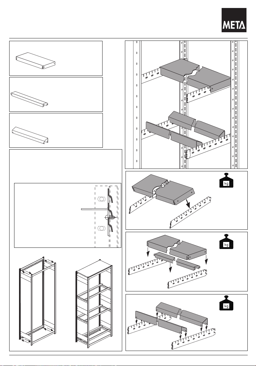
Page 48

Das Lagersystem
Ausziehbarer Fachboden
Stand 05.2009
Pull out shelf
Télsecopique à rallonage fond
Schubladenauszug
mit Draht und Feder
Drawer rail
Rail télescopique pour tiroir
Fachboden (1000 x 400 / 500 / 600)
Shelf
Fond
max. 70 KG
390
490
590
Montage der Auszüge siehe S.42
915
*Traglast bei gleichmäßig verteilter Last.
*Load capacity when loads evenly distributed.
*Charge portante lors d’une charge régulierement partie.
48
Page 49

260
Das Lagersystem
Sichtblende - Beleuchtung
Stand 05.2009
Facing panel - illumination
Auvent - éclairage
1
2
3
1.
M6 x 20
Sichtblende
Facing panel
Auvent
Leuchte
Lamp
Lampe
Display-Halteschiene
Display holder
Rail de support pour
étiquettes
Achtung:Die Leuchte darf nur vom autorisierten Elektriker angeschlossen werden !
Warning : Lamps may be fitted only by a qualifield electrician !
Attention : la lampe ne doit être raccordé que par un spécialiste ( électricien ) !
∅ 20 x 4
2.
2
B8 x 16
3
1
M6
3. 5.
4.
49
Page 50

Das Lagersystem
Vorsatzbodenträger und Vorsatzboden
Stand 05.2009
Attached shelf support and attached shelf
Support de planchette adaptable et planchette adaptable
1
Vorsatzbodenträger
Attached shelf support
Support de planchette
adaptable
1
2
C
2
Vorsatzboden
Attached shelf
Planchette adaptable
C
C
C
C
C
C
C
A
A
Beachten sie unbedingt folgende Hinweise:
- erforderliche Regalfelder ≥ 2
- Längsaussteifung der Regalfelder: kompl. mit Längsriegeln (vorne + hinten ), oder
Kombination Rückwand hinten - Längsriegel vorne
- Fußverdübelung bei letztem Regalfeld ( A )
- Endrahmen MHS - Ausführung ( B )
- Regalbestückung : 1. Normalfächer ( C ) , 2. Kragfächer ( D )
- Kraglänge ≤ Rahmentiefe
B
D
A
Please always observe the following information :
- Required rack modules ≥ 2
- Longitudinal bracing of shelf modules:Complete with longitudinal crossbar ( front + rear ) , or
- Feet of last rack module ( A ) anchored in floor
- End frame in MHS version ( B )
- Shelf assembly : 1. Standard shelves ( C ) , 2. Cantilever shelves ( D )
- Length of cantilever ≤ depth of frame
Combination rear wall at back and longitudinal crossbar at front
Observez strictement les indications suivantes :
- champs de rayonnage nécessaires ≥ 2
- renforcement longitudinal des champs de rayonnage:compl. avec barre longitudinale ( AV + AR ) , ou
- chevillage du pied au dernier champ de rayonnage ( A )
- cadre final exécution MHS ( B )
- équipement du rayon : 1. rayons normaux ( C ) , 2. rayons en porte à faux ( D )
- Longueur portante ≤ profondeur du cadre
combinaison paroi AR barre - longitudinale AV
50
Page 51

Das Lagersystem
Vorsatzbodenträger und Vorsatzboden
FK1
FK2
FK3
FKX
KL
KL FK max.
mm kg
300 35
400 25
500 15
Stand 05.2009
Attached shelf support and attached shelf
Support de planchette adaptable et planchette adaptable
1.
2.
FKX = FK1 + FK2 + FK3 < 150 kg
FK = Kragfachlast
gleichmäßig verteilte Last
= Cantilever shelf load
Evenly distributed load
= Poids du rayon en encorebellement
Charge régulièrement réparatie
KL = Kraglänge
Cantilever length
Longueur de l’ encorbellement
3.
51
Page 52

Das Lagersystem
Vorsatzpult
Stand 05.2009
Reading rest
Pupitre monté à l’avant
Vorsatzpult
Reading rest
Pupitre monté à’avant
1.
2.
M6 x 10
M6
3.
52
Page 53

META-CLIP
Das Lagersystem
Vorsatzleiste / Prospekthalter A4
Stand 05.2009
Z-rest / A4 brochure holder
Rebord avant / Présentoir pour prospectus A4
1
Vorsatzleiste
Z-rest
Rebord avant
2
2
Prospekthalter A4
A4 brochure holder
Présentoir pour
prospectus A4
1
B8 x 16
1
53
Page 54

Das Lagersystem
Notizen
Stand 05.2009
Notes
Notes
54
Page 55

Das Lagersystem
Notizen
Stand 05.2009
Notes
Notes
55
Page 56

Stand 05.2009
 Loading...