

Page 1

CONTENTS
Introduction
.....................................................................................................................................
1. Purpose
2. General recommendations
3. Technical data
4. Complete set of equipment
5. Design and operation principles
6. Operation procedure
..................................................................................................................................
....................................................................................................
.......................................................................................................................
...................................................................................................
...........................................................................................
............................................................................................................
6.1 Preparation for operation
6.2 Operation with electronic module
6.2.1 Beginning of work
6.2.2 “Measurement” mode
6.2.3 “Calibration” mode
6.2.4 “Processing” mode
6.2.5 Connection with computer
6.3 Probe operation
6.3.1 U1 ultrasonic probe
6.3.2 D1 dynamic probe
.............................................................................................
................................................................................
...........................................................................................
......................................................................................
.........................................................................................
..........................................................................................
...............................................................................
...........................................................................................................
..........................................................................................
............................................................................................
7. Technical maintenance and special conditions of operation
8. Precautions and troubleshooting
.........................................................................................
9. Manufacturer’s guarantee and service maintenance
..............................................
...........................................................
2
4
5
5
7
9
12
12
14
14
14
16
18
18
19
19
20
21
22
24
1
Page 2

INTRODUCTION
ThemanufacturerisMET Ltd. The CentreForPhysicalAndMechanicalMeasurements.
The License#000087-IRforproductionandmaintenanceofmeasuringequipmentwasissued
by the FederalAgencyforTechnicalRegulationandMetrologyofRF.Themailingaddressis:
POB 117,Moscow,124460, Russia.
The present Technical Reference and Operation Manual (hereinafter referred to as “TR”) is a
document which certifies the guaranteed by the manufacturer main parameters and technical
characteristicsofportablehardnesstesters in plastic / aluminum body of electronic module :
?Ultrasonic(MET-U1 / MET-U1A)
?Dynamic(MET-D1 / MET-D1A)
?Combined(MET-UD /MET-UDA)
MET-U1 Ultrasonic portable hardness tester is manufactured in compliance with TU 4271 –
001 – 18606393-01).
Certificate of Approval of this type measuring equipment #7951 is registered in SI State Register
under the number of 19623-00 and the equipment is recommended for application in the Russian
Federation.
Registration Certificate #MT 093 2004 is registered in the Industry Register of Measuring
Equipment Recommended to be used in Railroad Transport, Chapter “Measuring Equipment
Used in Locomotive Service”, in the Russian Federation.
Certificate of Approval of this type of measuring equipment #2567is registered in SI State
Register under the number of РБ 03 03 2047 03 and the equipment is recommended for
application in the republic of Byelorussia
.
Certificate of Recognition of Approval of this type of measuring equipment - Series E # 000980
– is registered in the State Register of measuring facilities under the number of # UA-MI/3p-6562004 and the equipment is recommended for application in Ukraine
under the number of 19623-
03.
Certificate of Recognition of Approval of measuring equipment # 2871 is registered in the
Register of the State System for Ensuring Uniform Measurement of the republic of Kazakhstan
under the number of KZ.02.03.01465-2006/19623-00, and the equipment is recommended to be
used and imported into the republic of Kazakhstan
.
MET-D1 Dynamic portable hardness tester is manufactured in compliance with TU 4271 –
003 – 18606393-03).
Certificate of Approval of measuring equipment, type #11910 is registered in SI State Register
under the number of 22736-02 and the equipment is recommended for application in the Russian
Federation.
Certificate of Approval of measuring equipment, type #2566 is registered in SI State Register
under the number of РБ 03 03 2046 03 and the equipment is recommended for application in the
republic of Byelorussia
.
Certificate of Recognition of Approval of this type of measuring equipment -- Series E #000982
- is registered in the State Register of measuring facilities under the number of #UA-MI/3p-6572004 and the equipment recommended for application in Ukraine
under the number of 22736-04.
2
Page 3

Certificate of Recognition of Approval of measuring equipment #2872 is registered in the
Register of the State System for Ensuring Uniform Measurement of the republic of Kazakhstan
under the number of KZ.02.03.01466-2006/22736-02, and the equipment is recommended to be
used and imported into the republic of Kazakhstan
MET-UD Combined portable hardness tester is manufactured in compliance with TU 4271 –
004 – 18606393-04).
Certificate of Approval of measuring equipment, type #11911 is registered in SI State Register
under the number of 22737-02 and the equipment recommended for application in the Russian
Federation.
Certificate of Approval of measuring equipment, type #2568 is registered in SI State Register
under the number of РБ 03 03 2048 03 and the equipment is recommended for application in the
republic of Byelorussia
Certificate of recognition of approval of measuring equipment, - Series E #000984 – is registered
in the State Register of measuring facilities under the number of #UA-MI/3p-658-2004 and the
equipment is recommended for application in Ukraine
Certificate of Recognition of Approval of measuring equipment #11469 is registered in the
Register of the State System for Ensuring Uniform Measurement of the republic of Kazakhstan
under the number of KZ.02.03.00433-2004/22737-02, and the equipment is recommended to be
used and imported into the republic of Kazakhstan
Hardness tester physical form may be slightly different from the models given in the pictures of
the present Technical Reference and Operation Manual. The manufacturer has the right to make
some changes in the tester design, which would not give any impact on the metrological
characteristics without any prior notification.
.
.
under the number of 22737-02.
.
3
Page 4

1. PURPOSE
1.1 Portable hardness tester (hereinafter referred to as the “hardness tester”) is designed to
measure hardness of metals and alloys. There are 8 independent hardness scales in the
hardness tester. Prior to the delivery, the manufacturer carries out the preliminary calibration
of hardness tester on 4 scales, Rockwell (HRC), Brinell (HB), Vickers (HV) and Shore
(HSD). Every scale in the hardness tester is calibrated on reference test blocks (i.e.
conversion tables are not used) graduated on the National Hardness Standards (Scientific
Research Institute for Physical-Technical and Radio-Technical Measurements (VNIIFTRI)
which is the main metrological institute of Russia in the field of hardness measurements, and
which keeps and maintains the state hardness primary standard machines on Rockwell and
Super-Rockwell (GET 30-94), Brinell (GET 33-85), Vickers (GET 31-06) and Shore D
(GET 161-04) scales.), which provides for the highest calibration level. Verification
Certificate of the approved by the state form is attached to every hardness tester.
1.2 In the hardness tester, there is also an tensile strength (R
) scale which, in compliance with
m
GOST 22791-77, enables to define tensile strength of carbon steel of pearlitic class by
automatic recalculation from Brinell hardness (HB) scale.
1.3 In the hardness tester, three additional scales (H1, H2, H3) are provided which make it
possible:
?toconducthardnesstestonotherscales(i.e.,RockwellB(HRB)scale,Superficial
Rockwell (HRNandHRT ) andother);
?toconduct hardnesstest on Leeb (HL) scale instead H1 scale during the measurement
by D1 dynamicprobe (rebound method);
? to conduct hardness test of metals which are significantly different by their properties
from steel (iron, aluminum and copper alloys etc.*).
To calibrate hardness tester, the user should dive not less than 3 samples of the tested article
material with different hardness (minimum, maximum and average).
Hardness tester calibration on the additional (H1, H2, H3) hardness scales can be made by
the manufacturer (according to the order, the service is free of charge) and the information
about it will be in the Technical Reference and Operational Manual (Attachment 2). The user
can make the calibration on additional hardness scales independently by himself following
the instruction of the present Technical Reference.
1.4 Hardness tester is equipped with microprocessor which enables to:
? Delete the measured hardness number in case of doubt in the correctness of the
measurement;
? Compute the average value of a series of the conducted measurements;
? Save the data in the non-volatile memory when hardness tester is switched off;
? Compute the average value from the data saved in the non-volatile memory;
? Transfer data from hardness tester non-volatile memory to the computer for further
printing out and diagramming;
1.5 The hardness tester enables to conduct hardness testing of a metal surface layer which was
fused, sprayed, mechanically or thermally or otherwise treated . Such hardness control is
impossible in case of fixed hardness testers which force through a superficial layer under big
loads. When hardness tester is used, the thickness of metal tested surface shall, at least, be
ten times more than the depth of the probe penetration (p.3). Hardness tester is designed for
non-destructive hardness control of large-sized equipment and the difficult for access places.
Such hardness control is not accessible for fixed hardness testers due to their technical and
design limitations.
Portable hardness testers in comparison with fixed hardness testers are characterized by a
higher productivity, the time of one measurement is 5 to 10 times less.
The hardness tester enables to conduct a quick test of a metal product hardness on site in the
process of operation or manufacturing, under the field or laboratory conditions in the sphere
4
Page 5
1.1 of mechanical engineering, metallurgy, power generation, ship building and railroad
transport, in aviation and space industry, in oil and gas sector, in maintenance and service
companies etc.
Pressure vessels of various purpose (reactors, steam generators, collectors, boiler drums, gas
holders etc.), turbine and generator rotors, pipelines, rolls, crankshafts, gears, parts of various
vehicles, industrial prefabricates articles (castings, forgings, sheets and plates) etc. (MI 2565-
99. Recommendations. “State System for Ensuring Uniform Measurement. Field of
application of hardness testing devices which are subject to verification”).
1.2 The hardness tester can be applied for
? assessment of technological processes stability (equipment treatment, welding etc.);
? diagnostics of equipment with the purpose of assessment of its remaining safe life
(hardness control of pipelines, boilers etc.).
2. GENERAL RECOMMENDATIONS
2.1 The thorough study of the present Technical Reference and Operation Manual is a
mandatory condition for the hardness tester application! Only in this case you can use all
hardness tester possibilities and avoid such actions and errors which are likely to result in the
wrong test results. Read the present Technical Reference and Operation Manual attentively and
only after it start examining the hardness tester.
2.2 Operator’s training requires sufficient knowledge in the field of metal hardness measurement
and metrology on the whole.
2.2.1 In the process of the hardness tester operation, there is always a set of external factors
influencing the test accuracy:
? the condition of the tested article surface (surface stress, contamination, various coatings;
? ambient parameters (humidity, temperature, pollution etc.);
? homogeneity of the tested article material (p. 2.2.4).
2.2.2 The tested surface and the tested article as such shall correspond to the parameters given
in the hardness tester specifications (paragraph 3) and be prepared in the due form
(p.6.1.2). Otherwise, the correct results obtaining is not guaranteed.
2.2.3 The highest accuracy of the results is obtained in the process of testing conducted under
the conditions listed below:
?ambienttemperatureis5...45ºC
? relative humidity is 30 …80%;
2.3 In the process of hardness tester operation, no impact or vibration on it is allowed.
? atmospheric pressure is 84 … 106 kPa.
Careful operation and observation of all technical instructions hereof is the condition for
its reliable operation without maintenance for quite a long period of time.
3. TECHNICAL DATA
Rockwell“C” 20…67 HRC ±2 HRC
Brinell 75…650 HB ±10 HB
Vickers
Shore23…102HV±2HSD
ConnectionwiththecomputerviaUSBport,diagrammingand
printingthedataout, data base
Measurements results processing, their averaging, recording and
archival data processing in the hardness tester memory
Non-volatile memory – data saving in archive when hardness Available
Scale Measurement range Error, not more than
75...999HV
Available
Available
±15HV
5
Page 6
Non-volatile memory – data saving in archive when hardness
Available
tester is switched off
Character LCD display: simultaneously displays a hardness
Available
scale, operating mode, archive number and discharge level
indication
LCD display lighting Available
The function of conversion from one hardness scale into another Available
Protective code excluding the possibility of an accidental
Available
hardness tester calibration reset
Hardness tester spatial position during measurements, no angle
correction is needed,
0
Number of current measurements for average value
0 … 360
1…99
determination
Battery (NiMH, C size) charging full time, hours
? Through AC line adapter
? Through USB port from a switched on computer
10
10
Time of uninterrupted operation with fully charged battery, not
- less than, hours:
- without lighting
- with lighting
- from AC mains
20
5
Unlimited
Hardness tester power supply:
- AC mains, V/Hz
- battery, V
consumed power, not more than, V-A
90-240 V, 50-60 Hz
1,2
1,5
Automatic power supply switch off, time, sec 150
Temperature range, ºC:
- during operation
- during storage and transportation
Relative humidity, % 30 … 80
Precious metals and stones
- silver, mg
- diamond (U1 ultrasonic probe), carat
Overall dimensions (length/diameter), max, mm
?electronicmodule in plastic body [in alum. body]
? carry case
Overall dimensions (length/width/height), mm
? ultrasonic probe
? ultrasonic short probe
? dynamic probe
? short dynamic probe
Mass (electronic module in plastic body [in alum. body]), kg:
- module + ultrasonic probe
- module + dynamic probe
- as a complete set (gross)
The number of testing result in the memory (archive) of the
module for every hardness tester probe 100
Time for one hardness testing, sec.
- ultrasonic probe
- dynamic probe
6
-5 … +45
- 15 … +65
16,8
0,07
145/80/40 [180/80/42]
240/180/75
160/225
80/40
140/25
80/25
0,36 [0,65]
0,31 [0.61]
1,0 [1.3]
4
2
Page 7
Tested surface roughness, R
- ultrasonic probe,
- dynamic probe
a
2,5
3,2
Tested surface radius of curvature, mm
- ultrasonic probe
- dynamic probe
5
10
Tested article mass, not less than, kg
- ultrasonic probe
- dynamic probe
0,01
3
Tested article thickness, not less than, mm
- ultrasonic probe
- dynamic probe
1
12
Size of indentation on the tested article surface with 45 HRC
hardness, mm
- ultrasonic probe
- dynamic probe
0,07
0,7
Depth of indentation into a tested article with 45 HRC hardness,
mm
- ultrasonic probe diamond pyramid
- dynamic probe hard alloy ball
30
300
Probe resource (minimum number of testing):
- ultrasonic probe
- dynamic probe
200000
50000
Pressureforceonultrasonicprobe,notlessthan,H9,8
4. COMPLETE SET OF EQUIPMENT
Name Piece, number
Electronicmodule in plastic or aluminum body 1
Case for hardness tester fixing on the forearm, belt, neck 1
Connecting cable for power supply and data transfer to the computer via
USBport 1
U1ultrasonicprobe(forMET-U1/U1A;MET-UD/UDAhardnesstesters) 1
Connectivecableforultrasonicprobe(forMET-U1/U1A;MET-UD/UDA
hardness testers) 1
D1dynamicprobe(forMET-D1/D1A;MET-UD/UDAhardnesstesters) 1
Connectivecablefordynamicprobe(forMET-D1/D1A;MET-UD/UDA
hardness testers) 1
Batterycharger1
NiMhbatteryCsize (plastic body) / AA size (aluminum body) 1 / 4
Carrycase1
TechnicalReferenceandOperationManual1
VerificationCertificateof“VNIIFTRI”FGUP1
USB Cableforcomputerconnection 1
CD with a software and technical support materials 1
7
Page 8
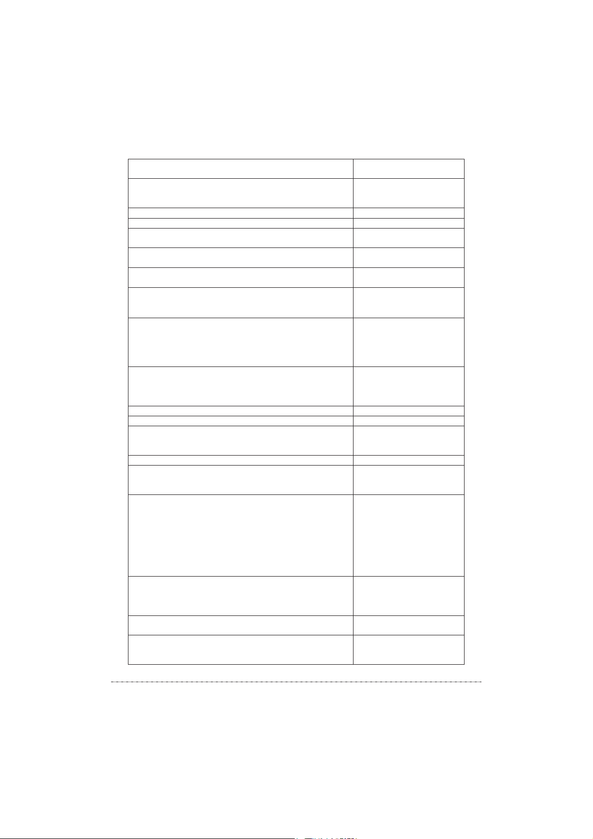
ADDITIONAL ITEMS
(shall be additionally paid)
Reference hardness blocks
(GOST 9031-75; 8.426-81) verified at FGUP “VNIIFTRI” for
hardness tester readings verification and calibration by user
MTR type (Rockwell): HRC, HRA, HRB
MTSR type (Super-Rockwell): HRN, HRT
MTB type (Brinell): HB
MTV type (Vickers): HV
MTSh type (Shore): HSD
Lapping fluid Dynamic probe: for setting test blocks and small-mass articles which were
preliminary fixed on to the testing plate. Ultrasonic probe
: for fixing articles thinner than 1 mm
to the supporting plate of the holder.
Stand for U1 ultrasonic probe is used for testing of small-sized items under the condition of
reliable fixin.
1) To fix the probe in the tube of the stand. 2) To install the spring on top of the probe.
3) To close the upper part of the tube by the iron cup, pressing the spring by the
cup when closing. 4) To install the stand with the probe and the electronic
modulus on the desk in the position convenient for the operator. 5) With the help
of the eccentric handle, to open the probe in the maximum upward position.
6) To put the tested item on the stand base. 7) With the help of collet fixture, by
moving the arm, to fix the distance between the probe tip and the test block
surface of not more than 1 mm. 8) To switch the instrument on and to measure
hardness by lowering the eccentric handle down.
INSTRUCTION FOR -U1 STAND OPERATION:
МЕТ
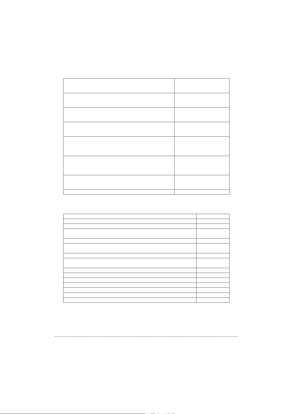
Battery operated grinder for preparation of testing area on the tested article, lessens surface
roughness, removes rust, wear hardening, scaling and joint weld processing.
Set of replaceable attachments for probes – for hardness testing of cylindrical and spherical
forms.
U1/2 short ultrasonic probe is a short model of U1 ultrasonic probe for testing within a limited
space (inner pipe diameter, sleeves etc.)
D1/2 dynamic probe is a short model of D1 dynamic probe for testing under the condition of
limited space.
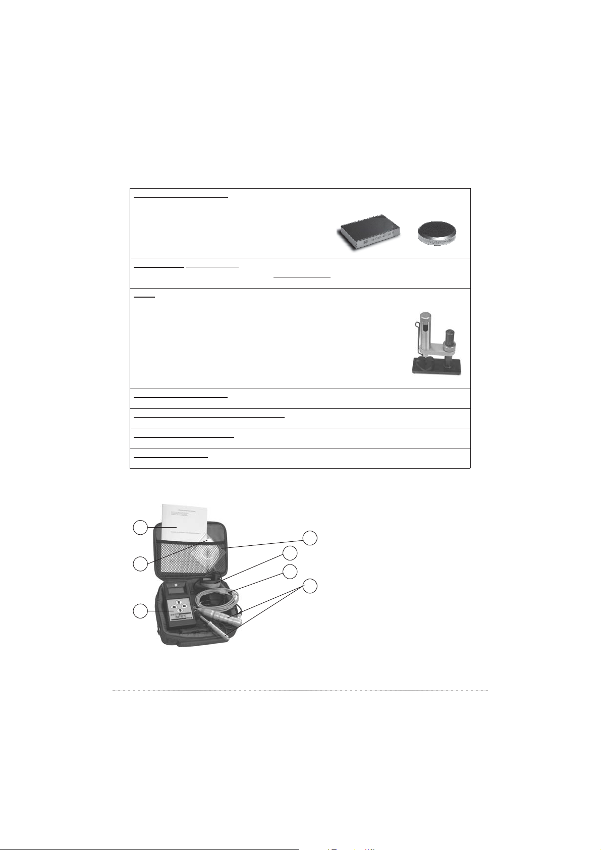
Hardness tester complete set (fig.1):
3
1
5
6
7
2
1 – carry case
2 – probes
3–
Technical Reference and
Operation Manual
4–
electronic module
battery charger
5–
CD
6–
USB cable for computer
7–
4
8
Page 9

5. DESIGN AND OPERATION PRINCIPLES
5.1 Hardness tester is a small-sized instrument designed to measure hardness. It consists of an
electronic module connected with a probe. The choice between ultrasonic and dynamic probe is
made depending on mass, configuration, structure, degree of mechanical and thermal treatment
of a tested article.
1
2
MET-UD combined portable hardness tester (fig.2):
1 – electronic module
2 — U1 ultrasonic probe
3 – D1 dynamic probe
3
Measurement result does not depend on the electronic module and probe spatial position.
5.2 Ultrasonic probe (ultrasonic contact impedance method – UCI) is a separate device
connected with electronic module by cable. Ultrasonic and dynamic probes differ in size only.
5
1
6
2
3
7
The probe basic part is a steel rod with Vickers diamond pyramid at the tip (the angle between
the facets is 136º), which as an acoustic resonator (vibrator) of the in-built ultrasonic frequency
self-excited oscillator. When the pyramid is forced on to the tested article under the calibrated
spring fixed load , the resonator natural frequency depending on the hardness of metal changes.
The oscillator natural frequency relative change is transformed by the electronic module into the
hardness number of the selected scale and is then shown on the display.
This method is suitable for hardness testing of articles with different mass and thickness
and, especially, of articles with thin walls and small mass.
The design of ultrasonic probe makes it possible to conduct testing without any visible imprints
on the surface in hard-reach places (for example, gear teeth etc.), of thin articles (for example,
pipelines etc.), where it is impossible to conduct measurements by dynamic probe.
It should be taken into account that the result of the testing conducted by ultrasonic method
depends on E - elasticity modulus of the tested article.
Limitation: it is not allowed to test articles with coarse-grain structure (for example, iron)
and articles with mass less than 10 kilo or thickness less than 1 mm!
In some separate cases, testing of an article with mass less than 10 kilo and wall thickness less
than 1 mm is possible but only under the condition of using additional accessories to ultrasonic
probe. For a consultation it is required to contact the manufacturer.
4
U1 Ultrasonic probe (fig.3):
1 – sleeve
2 – packing fit ring
3 – packing lower surface
4 – sleeve face
5 – probe body
6 – connective cable
7 – electronic module male connector
9
Page 10

RECOMMENDATION. To test articles with wall thickness less than 2 mm and R of surface
curvature less than 18 mm, it is recommended to use accessories to ultrasonic probe (holder,
replaceable attachments etc. – see paragraph 4)
5.3 Dynamic probe (rebound method) is a device connected with electronic module by cable. D1
dynamic probe and D1/2 short dynamic probe differ in size and spring retracting principle.
D1 dynamic probe (fig.4):
1 – start button
2 – the probe body upper part
3 – the probe body lower part
4 – inductor
5 – hammer
6 -- probe connector plug
7 – electronic module male connector
8 – tester body male connector
Hardness testing principle is based on the determination of the ratio of the stroke and rebound
speed of the hammer which is located inside the probe. At the end of the hammer, there is a
hardmetal ball which contacts directly with the tested surface at the moment of the stroke. Inside
the hammer, there is a permanent magnet. After pushing the start button and with the help of the
preliminary taken up spring, the hammer is forced on to the tested surface. During this process,
the hammer is moving inside the inductor and induces its own electro-motive force. The signal
from the inductor outlet is sent to the electronic module inlet where it is transformed into the
hardness number of the selected scale and is then shown on the display. Hardness testing is
carried out in compliance with ASTM A965-02 “Standard Test Method for Leeb Hardness
Testing of Steel Products”.
This method is suitable for hardness testing of massive articles, coarse-grain articles and
cast and forged pieces.
The probe design enables to conduct a large number of tests over a unit of time, and to operate it
does not require any special skills as, for example, in case of ultrasonic probe.
Limitation: it is not allowed to test articles with the mass less than 3 kilo or thickness less
than 12 mm!
Testing of articles with mass less than 3 kg and thickness less than 12 mm is possible if:
? cast iron testing plate (GOST 10905-86) or certified metal plate with the mass not less
than 5 kg is available;
? lapping liquid for the tested article lapping to the support plate is available;
? the testes article shall be lapped to the support plate TIGHTLY.
When testing of magnetized materials is carried out, the error may increase due to the steel
magnetic field impact on the readings of the hammer movement inside the inductance coil speed.
5.4 Hardness tester electronic module (fig.5)
isaseparatedeviceinaplastic or aluminum body:
1
2
3
*Onthefrontsidethereis:
1) LCD (hereinafter referred to as the “display”);
1
2) four functional push buttons (?, ?, ?, ?);
3) hardness tester type indication;
*onthebacksidethereis:
1)serialnumber;
6
7
5
:
1
2
3
4
1
2
3
4
2) hardness tester operation diagram;
3) manufacturer data;
4) closed compartment for battery;
10
Page 11

1 2
*on the upper end there is:
1) four-pin plug for connecting to a computer or a charger;
2) five-pin plug for probe connection
5.5 On the electronic probe back side, there is hardness tester operation diagram :(fig.6)
HRC HB HV HSD Rm H1 H2 H3
TEST CALIBRATION PROCESSING
Measurement & archive
Measurement on test block 1
Sample limits setting
and average value
Archive
Scale corection
determination
Measurement on test block 2
Scale corection
5.6 Menu is used for hardness tester operation control. Every level of the menu allows the
selection of parameters or modes of operation.
o The first level – “scale” – allows to choose the current (operational) hardness scale from
the following: HRC, HB, HV, HSD, R
ordered.
o The second level - “measurement-calibration-processing” - allows to select the current
(operational) hardness tester mode: measurement, calibration or processing.
o The third level – “YES/NO” allows to confirm or cancel the selected operation and get
back to the former operations by pushing ?button.
5.7 Push buttons ?and ?allow to choose the menu level, and push buttons ? and ? allow to
select a parameter within the level.
5.8 Hardness tester power supply.
5.8.1 The battery located in the closed compartment from the electronic module back side is the
source of the hardness tester power supply. Battery should be installed in compliance with given
polarity.
If hardness tester is not in operation for more than fourteen days, the battery shall taken out from
the electronic module compartment.
5.8.2 The battery charge indication is shown under “battery” symbol in the electronic probe
display upper part. Three dark squares inside the symbol show the battery full charge. As the
battery discharges, the squares disappear one by one from top to bottom. One dark square or
absence of any square means the necessity to charge the battery. “Battery” symbol is shown
on the display under any hardness tester mode of operation. 5.8.3 Battery charging can be from
AC mains through a charger .(fig.7)
, H1, H2 or H3 and also other scales as it is
m
11
Page 12

4
Charger
1 – red optical diode
USB port for power cable male connector2–
3 USB mail connector of power cable–
4 – 4-pin plug of connective cable for connecting
to electronic module
It is allowed to charge the battery and work with the hardness tester simultaneously.
It is prohibited to connect the charger to the electronic probe without the battery.
5.8.4 The charger is connected to the electronic module (with the installed battery only!) through
connective power cable pin plug is equipped with a rotating cylindrical. Connective cable fourlock (fig.8).
To connect the charger, make the following steps:
o Turn the lock counterclockwise up to the stop;
o Bring the plug of the charger into coincidence with the electronic module plug so that they
coincide;
o Insert the plug up to the stop by pushing slightly;
o Turn the lock clockwise up to the stop.
A specific flick of the lock confirms that the operation was done correctly. The charger is
connected to the electronic module. Plug in the USB connective cable. The charger is switched
to the electronic module.
5.8.5 Connect the charger to the AC mains. When the power is on, the optical diode will be red.
The battery charging process has started. After the charger has been connected to the AC mains,
the “battery” symbol squares on the switched on hardness tester
display will get one by one darker from bottom to top. It means that the
battery charging has begun. In the process of charging, the battery and
the charger case may get slightly warm which is not a defect.
5.8.6 The battery can be charged via USB port. To charge hardness test (with the installed
battery) via USB port, first connect a four-pin plug to the hardness tester electronic module (see
paragraph 5.8.4) and after that USB port plug to the computer. The battery charging process has
started. Hardness tester itself shall be switched off.
5.8.6 Hardness tester NiMh battery does not contain any heavy metals harmful for health.
Nevertheless, for environmental protection purpose, do not throw used batteries away to the
household rubbish container. You may send it back to the manufacturer or utilize in compliance
with the rules for used batteries utilization.
(fig.9)
3
1
2
lock
6. OPERATION PROCEDURE
6.1 PREPARATION FOR OPERATION
6.1.1 VISUAL INSPECTION
Make visual inspection of the device, make sure that there is no mechanical damage of the
electronic probe, connective cable. Check the integrity of the seals on the electronic module (in
the battery compartment) and the probe. (paint on the thread connection). Inside the probe, there
is a seal destroyed when the probe is disassembled (shall be opened by the manufacturer
only!)
12
Page 13

6.1.2 TESTED ARTICLE PREPRATION
The mandatory requirements to the tested article:
? During the testing period, the tested article shall be under no load from the main
operational loads.
? The article mass and thickness shall comply with paragraph 3 requirements.
The mandatory requirements to the article surface shall correspond to the parameters given in
? The roughness and radius of curvature of the tested surface shall correspond to the
parameters given in paragraph 3.
? The area of the tested surface shall be free from humidity or contamination (oil, dust
etc.), lubricants, scale, oxide film, rust.
? The distance between the supposed centre of the tested area and the edge of the tested
article surface or the next imprint shall not be less than 3,5 of the diameter (length of
diagonal) of the imprint (paragraph 3).
? In case there is a decarburized layer, surface hardening or nitration case within the tested
area, this surface layer shall be removed (only for U1 ultrasonic probe).
To prepare the area of the tested surface it is recommended to use grinder (additional equipment,
paragraph 4) or polishing paper, after that it is necessary to clean the area with a cleaning cloth.
In the course of the surface preparation procedure it is necessary to take the precaution measures
against the possible change in the hardness of the tested article due to heating or hardening of the
tested surface in the process of the mechanical treatment. The recommend depth of the layer to
be removed:
Forged or drop forged surface : not less than 2 mm;
? ? Cast articles surface : not more than 4 mm;
For pipes : from 4% to 5% from the wall thickness, but not more than 2 mm.?
6.1.3 PROBE CONNECTION
Probe shall be connected to the electronic module by a connective cable. The connective cable
connection to:
? U1 ultrasonic probe
: plug the cable into the probe connector hole and move it as far as it
will go, after that tighten the metal fixing device;
? D1 dynamic probe
: plug into the inductor connector hole as far as it will go (in some
models, there is no such connector hole)
Probe with the connective cable is connected to the electronic module through five-pin plug
equipped with a rotating cylindrical lock (paragraph 5.8.4).
To connect the probe, make the following steps:
o turn the lock counterclockwise up to the stop;
o bring the five-pin probe plug into coincidence with the electronic module plug so that
they coincide;
o Insert the plug up to the stop by pushing slightly;
o Turn the lock clockwise up to the stop.
A specific flick of the lock confirms that the operation was done correctly. The probe is
connected to the electronic module.
6.1.4 POWER SUPPLY SWITHCING ON
o Press ?button for some time (-2 sec);
o After switching for a short time the words “probe connection” will appear for a short time
(-2 sec);
o Electronic module will recognize the type of the connected probe and the relevant words,
either “ultrasonic probe” or “dynamic probe” will appear on the display (-2 sec);
o After these steps, hardness tester will automatically start operation in the mode which
was used before it was switched off.
13
Page 14

6.1.5 POWER SUPPLY SWITHCING OFF
o Power supply switching off takes place automatically without any operation with push
buttons or probe (-150 sec)*;
o It takes place if ? and ? buttons are pushed simultaneously;
o It takes place in case the battery is discharged;
* Due to the hardness tester power supply automatic switch off, the time of its operation
increases without any additional battery charging.
6.1.6 DISPLAY LIGHTING
Display lighting is switched on and off by short-time (-1 sec) pushing ?button from the menu
first level (scale).
Hardness tester operation under the negative ambient temperature (<0C) shall be with the
lighting on.
Attention! Operation with display lighting reduces the time of the device operation since
the battery charges faster!
6.2 OPERATION WITH ELECTRONIC MODULE
6.2.1 BEGINNING OF WORK
6.2.1.1 SCALE SELECTION
o Start work with the first level – “scale” – by pushing ?button. In the display upper part,
words “XXX scale” will appear, where “XXX” is a hardness scale (paragraphs 1.1 and 1.3),
and in the display right side, “battery” symbol will appear (5.8.2).
o Select the hardness scale you need by pushing ? and ? buttons.
o Confirm the selection of the required for you hardness scale by pushing ?button. After that
you will get to the second level automatically.
6.2.1.2 OPERATION MODE SELECTION
o Select the required for you operation mode – “measurement” or “calibration”, or
“processing” by pushing ? or ? buttons.
o Conform the required for you mode by pushing ?button. The hardness tester is ready for
operation.
6.2.1.3 OPERATION CANCELING
To cancel an operation or to return to the previous one use ?button.
6.2.2 “TESTING” MODE
6.2.2.1 “Measurement” mode and all operations within this mode shall be conducted separately
for U1 ultrasonic probe and D1 dynamic probe. The given below operations can be performed in
this mode:
o archive
o testing and recording
6.2.2.2 “ARCHIVE” OPERATION
Hardness tester operation in “measurement” duty always starts with the “Archive” operation.
Indication on the display is shown on the figure below (fig.10):
HV
838
Archv. ?: 63
Attention! During the first operation it is recommended to skip the “archive” operation
and proceed with “measurement and recording” operation. For this purpose, push ?
button and then got to paragraph 6.2.2.3.
14
Page 15

6.2.2.2.1 The meaning of words and symbols on the display
“HV” Vickers hardness scale;
“838” the measured value on Vickers scale;
“Archive #63” - the number of the archive cell in which measurement #838 on Vickers scale
(HV) is stored;
“battery” is battery charge symbol.
6.2.2.2.2 Archive cell number changing
The change of the archive cell number is done by pushing ? or ? buttons. The change of the
archive cell number (Archive #63) will result in the change of the readings of the measured value
(838) into the readings of another measured value saved under the relevant archive number (#61;
63; 60, 64 etc.). The hardness scale (HV), however, will remain unchanged.
It means that if you conducted your measurement on HRC scale and sent it to the archive under
#3 and #4, and the archive is looked through from HV-838-Archive #63, the hardness tester will
automatically transfer HRC and HB hardness scales into HV scale and will show the values of
cells ##1, 2, 3 and 4 on HV scale.
6.2.2.2.3 Conversion of the measured value from one hardness scale into another
? select the scale you need (paragraph 6.2.1.1)
? turn to “archive” operation (paragraph 6.2.2.2)
? by pushing ? or ? buttons, look through the archive;
? all values obtained earlier in other hardness scales will be automatically converted into
the selected by you scale.
Attention! Conversion from one hardness into another has an error.
6.2.2.2.4 To process data in the archive, (mean value computing and archive clearing) switch to
“processing” mode (paragraph 6.2.4)
6.2.2.3 MEASUREMENT AND RECORDING” OPERATION
6.2.2.3.1 Start “measurement and recording” operation by pushing ?button in order to finish and
go out from the “archive” operation. Indication on the display is shown on the figure below
(fig.11).
HB
07
375
Measur ?: 01.
6.2.2.3.2
“ ” Brinell hardness scale;
“ ” current measurement number
“ ” the measured value on Brinell hardness scale (HB);
“measurement №01” the number of the archive cell which is offered for recording of the
measured value on Brinell hardness scale (HB);
“probe” symbol of the probe;
“battery” symbol of the battery.
6.2.2.3.3 Blinking probe symbol means that the hardness tester is ready to conducting
measurements. How to use the probe in the process of “measurement and archive” operation is
described in paragraph 6.3. After the sound signal, the measured on the selected by you hardness
scale value appears on the display (paragraph 6.2.1.1). The measurement number (07) and the
measured value (375) on the hardness scale (HB) correspond to every conducted measurement.
The archive cell number (measure №01) remains unchanged.
6.2.2.3.4. Conducted measurements mean value is computed by pushing ?button. The number of
measurements which are taken for the mean value calculation is show in the current
measurement number (07), i.e. having conducted 7 measurements and by pushing ?button, you
will obtain the mean value.
After the mean value computation, the hardness tester will automatically start the “archive”
operation for you to save the obtained result. If you do not want to save the result and want to
continue your measurement, push ?button to switch to “measurement and recording” operation.
The meaning of words and symbols on the display.
HB
07
375
15
Page 16

6.2.2.3.5 Deleting measurement hardness value
(375) within the “measurement and recording”
operation is made by ? button pushing. It is recommended to delete the last measurement result
in case there appear some doubts in the correct measurement procedure.
6.2.2.3.6 Recording in the archive
shall be started from selecting the cell number and “archive”
operation (paragraph 6.2.2.2.2), after that go to “measurement and archive” operation by pushing
?button.
o to set -00- in the current measurement (07), transition from “measurement and recording”
operation to “archive” and back by pushing ?button two times shall be performed;
o Recording the measured hardness value (375) or mean value (paragraph 6.2.2.3.4) into the
archive is done by ? button pushing. In doing so, the number of the archive cell for
measurement recording (measure №01) will be automatically increased by 1 (measure №2).
o It is recommended to set “00” in the current measurement number for every new set of
measurements.
o Recording into the archive of the measured hardness number (375) or mean value (paragraph
6.2.2.3.4) shall be made by pushing ?button. In this case, the number of the archive cell for
measurement recording (measure №1) will remain unchanged. This is convenient for
changing the archive cell content .
6.2.3 “CALIBRATION” MODE
6.2.3.1 Shall be carried out by highly skilled personnel only and only in the case of production
necessity.
It is not allowed to use reference hardness blocks the shelf life of which has expired (2 years
from the last comparison) or the surface of which was used by more than half (GOST 9031-75)
6.2.3.2 “Calibration” mode and all operations under this mode shall be performed separately for
U1 ultrasonic probe and D1 dynamic probe.
It is recommended to perform hardness tester operation in “calibration” mode when not less than
two squares of the battery charge indication is on.
6.2.3.3 The process of hardness tester calibration by users means bringing mean hardness value
of a reference hardness block measured by the hardness tester into the line (equality) with its
nominal value (engraved on one of its sides in compliance with GOST 9032-75).
Hardness tester calibration by users on HRC, HB, HV, HSD scales allows to introduce a
correction to hardness tester calibration established by the manufacturer straight after the
hardness tester had been manufactured. (paragraph 1-1). Calibration makes it possible to restore
the accuracy of hardness tester readings under the condition of the possible wear and tear of the
probe mechanical parts (spring, hammer) in the process of long and intensive operation.
6.2.3.4 It is recommended to perform hardness tester calibration by users in the period between
verifications in the listed below cases:
o If in the process of the hardness tester verification on the reference hardness block the
readings are stable but differ from the nominal value of the reference hardness block;
o after long period of storage (more than 3 months);
o After intensive operation (more than 200.000 measurements for U1 ultrasonic probe and
50.000 for D1 dynamic probe);
o In case of considerable change in the conditions of operation (ambient temperature, humidity
etc.)
6.2.3.5 For hardness tester calibration by user, it is necessary to have two reference hardness
blocks with maximum and minimum values on the controlled part of the hardness scale.
Examples:
o For calibration along the whole “C” Rockwell scale, TWO reference hardness blocks are
required with the values of (25?5) HRC and (65?5) HRC.
o If you do not use the whole range of “C” Rockwell but only the range of 20?40 HRC,
perform the calibration on reference hardness blocks with the values of (25?5) HRC and
(45?5) HRC.
16
Page 17

6.2.3.6 “CALIBRATION” OPERATION
Select the scale (paragraph 6.2.1.1) and enter into “Calibration” mode. (paragraph 6.2.1.2).
6.2.3.6.1 Enter the code (it is in the sealed envelope inside the Technical Reference and
Operation Manual). Push ?button. The display indication in the “Calibration” mode is show on
the Figure below (fig.12).
HRC
02
64,2
Calib. ?: 02
6.2.3.6.2 The meaning of words and symbols on the display
“HRC” Rockwell hardness scale;
“02” current measurement number
“64,2” the measured value on Rockwell hardness scale (HRC);
“Calibrat№2” calibration number;
“probe” blinking symbol;
“battery” symbol of the battery charge.
6.2.3.6.3 Measurements on reference hardness block #1 (step 1) – obtaining of mean hardness
number. Take one reference hardness block. Conduct not less than FIVE measurements!
Average the obtained values by pushing ?button. Confirm the end of this step by pushing ?
button.
6.2.3.6.4 Correction (step 2) – bring into the line (equality) the measured by the hardness tester
MEAN and NOMINAL hardness value (paragraph 6.2.3.3). By pushing ? or ? buttons change
the MEAN value of the hardness tester up to the NOMINAL value on the hardness reference
block. When the value coincide (become equal), push ?button.
6.2.3.6.5 Measurement on reference hardness block №2 (step3) –repeat the actions described
in paragraph 6.2.3.6.3.
6.2.3.6.6 Correction (step 4) – repeat the actions described in paragraph 6.2.3.6.4. Pushing ?
button will lead to the completion of the step and going out from “Calibration” mode.
6.2.3.6.7 Verification of the hardness tester re adings after the conducted calibration.
Measure the hardness of reference hardness block №1 (not less than 5 measurements) and
compute its mean value (paragraph 6.2.2.3.4). The obtained value shall correspond to its nominal
value within the hardness tester error (paragraph 3).
If the obtained value exceeds the hardness tester error limit (paragraph 3), then perform “CLEAR
(paragraph 6.2.3.5)
6.2.3.7 “CLEAR CALIBRATION” OPERATION
6.2.3.7.1 Hardness tester calibration by users requires highly skilled professional personnel. If
you failed to introduce the correction to the hardness tester calibration for the second time or if
you doubt the results of the conducted “Calibration” operation, it is recommended to perform
“Clear cal.” operation. To obtain technical support, keep in touch with the maintenance service
of the hardness tester manufacturer.
6.2.3.7.2 To clear calibration correction introduced independently, perform the following steps:
o select the scale (paragraph 6.2.1.1);
o enter “Calibration” mode (paragraph 6.2.1.2);
o enter the code;
o push ? button.
After performing “Clear cal.” operation the hardness tester will get to the initial hardness tester
calibration set by the manufacturer straight after manufacturing (paragraph 1.1)
function (paragraph 6.2.3. ) and repeat “CALIBRATION” operationCALIBRATION” 6
.
.
17
Page 18

6.2.4 “PROCESSING” MODE
6.2.4.1 “Processing” mode and all operations within this mode shall be conducted separately for
U1 ultrasonic probe and D1 dynamic probe.
6.2.4.2 Within this mode the listed below operations can be carried out:
o compute mean value;
o clear archive.
Select the scale (paragraph 6.2.1.1). Enter the “processing” mode (sequence of buttons is:
???). Select the necessary for you operation by ? or ? button and confirm your selection by
pushing ?(yes).
6.2.4.3 “MEAN VALUE” OPERATION
“Mean value” operation is used for mean value computation within any interval of the archive
cell (sample interval). Display indication is shown on the Figure below (fig.13).
HSD
96,7
>01 07Avrg.
6.2.4.3.1 The meaning of words and symbols on the display
o “HSD” Shore hardness scale;
o “96,7” mean hardness value on Shore scale (HSD);
o “>01 mean 07” sample interval;
o “battery” battery charge symbol.
The display shows the result of the hardness mean value (96,7) on Shore scale (HSD) for the
archive cells from number one through number seven (<01 mean 07)
6.2.4.3.2 Setting the limits for sample mean value computation:
o Push ?button to move < or > sign to the left initial (>01) or the last right (<07) sample limit;
o Every push of ? or ? button will decrease or increase the left (>01) and the right (<07)
number of the sample limits by one;
o The sample mean value is computed and shown on the display automatically (“96,7”)/
“Mean val.” operation does not change the archive cells content. “Mean val.” operation is
performed only for filled in cells within the sample limits.
6.2.4.4 “CLEAR ARCHIVE” OPERATION
“Clear archive” operation is designed for deleting from the hardness tester memory ALL content
of the archive cells, i.e. reducing to zero of ALL data.
In the “Processing” operation mode, select “clear archive” operation by pushing ? or ? button.
Push ?(yes) button. The words “Please, wait, clear archive” will appear and in two seconds the
archive will be deleted.
6.2.5 CONNECTION WITH COMPUTER
6.2.5.1 The function is for date transfer from hardness tester non-volatile memory (“archive”
e, paragraph 6.2.2.2) to the computer for the purpose of saving, processing, looking through
mod
and selection from the general volume what is necessary for graphs preparation and the further
printing out of the results.
6.2.5.2 Hardness tester soft-are is suitable for WINDOWS (from 98 version to XP).
6.2.5.3 Operation procedure
? Connect the power and data transfer cable to hardness tester electronic module through
four-pin plug (paragraph 5.4) and to the switched on computer via USP port. It is not
required to switch the hardness tester on.
? Insert the attached CD into the computer.
? Install USB driver from “InstallDRVMET” file in compliance with the “Instructions for
USB driver installation”.
? Install “MET hardness tester” soft-ware going to “InstallMET” file and double clicking
on “SETUP_EXE_EXE” file.
18
.
Page 19

? Operate “MET hardness tester” software going to “All software” in the start menu on
your computer.
? In the opened window, of “MET hardness tester” soft-ware, push “?Help” button and set
the operation of the computer with the hardness tester in compliance with “Inquiry”
section.
6.2.5.4 When hardness tester is connected to the switched on computer via USB port, the
battery charging takes place.
6.3 WORK WITH PROBE
6.3.1 U1 ULTRASONIC PROBE
6.3.1.1 Check if the probe packing for (yellow colour, hereinafter referred to as the “packing”) is
installed correctly: the end face of the probe sleeve shall coincide with the packing lower
surface. If the end face is deepened into the sleeve or sticks out, it shall be reinstalled. For this
purpose, unscrew the packing fit ring, match the packing lower surface with and the sleeve end
face in one surface, screw the sleeve fit ring.
Check whether the sleeve has been installed properly before the beginning of
measurement!
6.3.1.2 Fulfill the requirements to the tested article (paragraph 6.1.3), connect the probe to the
electronic module, switch on the hardness tester power supply (paragraph 6.1.4) and turn to the
“measurement” duty (paragraph 6.2.2.3).
6.3.1.3 Ultrasonic probe is extremely sensitive, that is why to operate it, the user should have
special skills and habits. In the process of testing, the article shall be fixed and the probe shall be
installed perpendicular to the measurement area. To avoid any damage to the diamond pyramid,
do not install and move the probe sharply along the tested surface. After pushing on the probe, it
is PROHIBITED to move it along the article surface!
To avoid wrong actions in the process of testing and to ensure reliable fixing, it is recommended
to use additional accessories to U1 ultrasonic probe: holder, lapping fluid, replaceable
attachments for cylindrical and spherical surfaces (paragraph 4).
6.3.1.4 THE FIRST MEASUREMENT
Loading diagram for U1 ultrasonic hardness probe (fig.14):
insta ll the probe make a light effort increase the effort keep the effort stop the effort
1,5 kg
S
measurement area resistance stop
o Blinking of “probe” symbol on the display means that the hardness tester is ready to conduct
measurements.
o Install the probe with its packing lower surface to the measurement area of the tested
article. Press the packing with two fingers of one hand to the measurement area and keep it
stable in the process of measurement. Take the body of the probe in the other hand.
o Press into the probe body slightly until the first resistance – diamond pyramid of the rod
comes up against the surface. Increase the effort immediately until the second resistance
(stop) – the diamond pyramid is forced into the surface. The effort should be made
smoothly*. Be sure that your hand does not shake so that the probe body is stable. For the
probe correct operation, it is necessary to apply an effort of not less than 14,7 N (1,5 kgf) to
its body and keep is stable in the process of measurement. Do not be afraid to apply an
excessive effort to the probe body, it will be limited by the stop.
19
Page 20

o Keep the constant effort on the probe body during 3-4 seconds. “Probe” symbol on the
display will stop blinking.
o After the sound signal and appearance of the hardness value on the electronic probe display,
stop making the effort on the probe body. The “probe” symbol on the display will start
blinking again, and the probe body will under the spring effort return to the initial position.
The first measurement has been completed, and the hardness tester is ready for the next
measurement.
*In case of sharp pressing on to the probe body, diamond pyramid can hit the surface of the
tested item, and due to this the measured hardness value will be incorrect.
6.3.1.5 EXPERIMENTAL MEASUREMENT
It is advisable to consider the first measurement as experimental measurement. In order to
acquire some experience of how to use the probe, it is recommended to conduct a number of
experimental measurements.
o After experimental measurement conducting, push ? button to delete the result and
exclude it from the article mean hardness value computation (paragraph 6.2.2.3.5).
o After a number of experimental measurements has been conducted for the purpose of
acquiring some experience of using the probe, you may use “Clear archive” function to
delete the results of the experimental measurements (paragraph 6.2.4.4).
6.3.1.6 ACQUIRING SOME EXPERINCE OF WORKING WITH THE PROBE
6.3.1.6.1 To acquire experience of working with the probe, it is recommended to use reference
hardness blocks. Measure the hardness of a reference hardness block (not less than 5
measurements) and compute its mean value. If the obtained value does not correspond to the
number of the reference hardness block, conduct one more measurement.
6.3.1.6.2 If the hardness tester readings are stable and the obtained mean value corresponds to
the reference hardness block rated value considering the hardness tester error (paragraph 3), you
may further proceed with the hardness tester.
6.3.1.7 The rules of U1/2 short probe operation are similar to those for U1 ultrasonic probe.
Holders for U1/2 are not produced.
6.3.2 D1 DYNAMIC PROBE
6.3.2.1 Be sure that the requirements to the tested article (paragraph 6.1.2) are observed, connect
the probe to the electronic module (paragraph 6.1.3), switch the power supply on (paragraph
6.1.4) and turn to the “measurement” mode (paragraph 6.2.2.3).
6.3.2.2 In the process of measurement, the article shall be fixed and the probe shall be fixed
perpendicular ! to the measurement area. At the moment of start button pushing, IT IS NOT
ALLOWED to move the probe along the tester surface.
6.3.2.3 THE FIRST MEASUREMENT
o Blinking of “probe” symbol on the display means that the hardness tester is ready to conduct
measurements.
o Install the probe to the article measurement area. With your one hand hold the inductor (the
probe lower body), with the other hand, hold the probe upper body. The upper probe body
shall be then moved to the lower body up to the stop and then set it free. The spring is taken
up and the probe upper part returns to the initial position independently.
o Press the launch button in the probe body upper part smoothly. Be sure that the probe does
not move and is properly pressed to the measurement area.
o After pushing the launch button and the hammer stroke at the measurement area, there will
be a sound signal after which the indication of the measured hardness value will appear on
the electronic module display.
6.3.2.4 EXPERIMENTAL MEASUREMENT
It is advisable to consider the first measurement as experimental measurement. In order to
acquire some experience of how to use the probe, it is recommended to conduct a number of
experimental measurements.
20
Page 21

o After experimental measurement conducting, push ? button to delete the result and
exclude it from the article mean hardness value computation (paragraph 6.2.2.3.5).
o After a number of experimental measurements has been conducted for the purpose of
acquiring some experience of using the probe, you may use “Clear archive” function to
delete the results of the experimental measurements (paragraph 6.2.4.4).
6.3.2.5 Attention: the minimum distance between the measurement points (imprints) shall
be not less than 3 mm. Repeated measurements in one and the same point are not
admissible since it results in the increased hardness value indication due to the metal
hammering harden in the imprint area.
6.3.2.6 ACQUIRING SOME EXPERINCE OF WORKING WITH THE PROBE
6.3.2.6.1To acquire experience of working with the probe, it is recommended to use reference
hardness blocks. Measure the hardness of a reference hardness block (not less than 5
measurements) and compute its mean value. If the obtained value does not correspond to the
number of the reference hardness block, conduct one more measurement.
6.3.2.6.2 If the hardness tester readings are stable and the obtained mean value corresponds to
the reference hardness block rated value considering the hardness tester error (paragraph 3), you
may further proceed with the hardness tester.
6.3.2.7 The rules of D1/2 short probe operation are similar to those for D1 ultrasonic probe. The
difference is only in the mechanism of spring taking up (paragraph 6.3.2.3). To take it up, it is
necessary to use the metal rod attached to short probes with the help of which the hammer
should be placed back into the probe till the stop.
7. TECHNICAL MAINTENANCE, SPECIAL CONDITIONS OF OPERATION
7.1 On the whole, hardness testers do not require any special maintenance. However, for the
purpose of hardness tester stable operation, regular maintenance is advisable.
7.2 PROBE MAINTENANCE
Clean hardmetal ball and diamond pyramid from dust, mud and oil traces. Use soft cloth
impregnated with alcohol solution.
Check the probe operation regularly by conducting hardness measurements on hardness
reference blocks. Do not use reference test block with expired period between verifications
(more than 2 years).
7.3 ELECTRONIC MODULE MAINTENANCE
To clean from any pollution, use soft dry cloth. Do not use the water, since the hardness tester is
neither spray-proof nor water-proof due to the joints on its body.
Do not use any solvents, they can damage indication signs and writings on the front and back
sides of the body.
7.4 BATTERY MAINTENANCE
Thebatteryaveragelifeisnotlessthan3years.Thebatteryusedincompliancewiththe "C" or
"AA" internationalstandard.Itisdonefortheconvenienceofitsreplacementwhenitisrequired
or sharp reduction of the continuous operation time (paragraph 3) independently of the country..
Replacement is possible only by the battery with similar characteristics in compliance with the
marking on it. From environmental protection point of view, the best thing is to use the battery.
7.5 STORAGE
7.5.1 Hardness tester shall be kept in the carry case, the probe and the battery shall be
disconnected. We recommend to keep Verification Certificate in the carry case inner pocket.
7.5.2 If hardness tester is kept in the carry case for than 14 days, the battery shall be taken out
from its compartment in the electronic module.
7.5.3 It is recommended to keep hardness testers in closed premises with the relative humidity
not more than 80%, there shall be no mold, paints, acids, chemical agents and other chemicals,
the evaporation of which my give a harmful effect. Sharp fluctuations of temperature and
humidity which can result in dew formation are not allowed.
7.5.4 It is recommended to keep hardness testers in the carry case in any spatial position not
more than 5 pieces put on one another which is relevant to the load of 5 kg under the condition
of its even distribution along the carry case surface.
21
Page 22

7.6 TRANSPORTATION
7.6.1 Hardness testers transportation in the carry case shall be only in closed vehicles, where the
possibility of mechanical damage or atmospheric precipitation is excluded.
7.6.2The way packed in carry cases hardness testers are located inside the vehicle shall exclude
the possibility of their free movement both inside the carry case and inside the vehicle.
7.7 PUTTING INTO OPERATION AFTER STORAGE AND TRANSPORTATION
7.7.1 After storage or transportation under the temperature lower than -5°C, before starting
hardness tester operation, it is necessary to keep it not longer than 1 hour under the temperature
higher than +10°C and not less than 2 hours under the temperature higher than 0°C.
7.7.2 Before operating hardness tester which was stored for more than 3 months and transported
for more than 2 months, it is necessary to check such hardness tester on the reference hardness
test blocks. If the measured AV EARGED value of the hardness tester does nor correspond to the
reference hardness test block NOMINAL value within the error limits (paragraph 3), it is
necessary to calibrate the hardness tester (paragraph 6.2.3).
7.8 SPECIAL OPERATION CONDITIONS
7.8.1 Increased dust content and humidity
. Put the electronic module of hardness tester into a
transparent plastic bag. Tighten it at the level of connective cable a bit lower than the probe plug.
After the work under such conditions is finished, electronic module shall taken out of the plastic
bag and air it.
7.8.1 Negative temperature (<0°C)
. Electronic module is the most sensitive to low temperature
part of hardness testers, especially it is true for LCD. That id why it is mandatory to switch the
display lighting on (paragraph 6.1.6). If there is a possibility, keep hardness tester closer to your
body and protect id with your coat or keep in the inside pocket, taking it out time from time for
inputting the data into the archive.
8. PRECAUTIONS AND TROUBLESHOUTING
8.1 Treat the hardness tester with care. Any wrong treatment may result in the violation of the
present Technical Reference and Operation Manual regulations and, thus, lead to the
manufacturer hardness tester warranty cessation.
8.2 Always check the integrity of the cables, electronic module and probe. Provide immediate
replacement of the damaged parts by the original ones. This job shall be performed by skilled
personnel.
8.3 Do not expose the hardness tester to aggressive chemical medium.
8.4 Do not leave the hardness tester in the direct Sun.
8.5 Do not sink the hardness tester into any liquids. If the hardness tester gets wet, take the
battery out and leave for 24 hours to get dry.
If the hardness tester is used under the increased humidity or dust conditions, place the electronic
module into the plastic bag. After work period is over, it is mandatory to get the hardness tester
dry.
8.6 The list of the possible problems in the process of hardness tester operation is given in the
Table below.
22
Page 23

Problem Reason Solution
switch on
Readings on the
display do not
change
Display switched off
in the process of
measurement
Probe blinking
stopped in the
“measurement”
mode
Measurements
results are stable but
differ from reference
hardness block
nominal value
Big range of the
measurement results
The battery is discharged Charge (p. 5.8.4) or replace (p. 7.4)Display does not
The battery is not installed
correctly
There is no contact in the
connector of the probe with the
electronic module
Break in the connecting cable or
connector; fault of the probe of
electronic module
Testing of articles which do not
correspond to the hardness tester
specifications (paragraph 3), for
example, low hardness of the
article
Reference hardness test block has
expired inter-verification period
(more than 2 years)
The spring of the probe has been
worn out after long life
The tested material has not uniform
in its structure.
Tested area has not been prepared
properly
The diamond pyramid or hardmetal
ball are polluted.
The diamond pyramid tip or
hardmetal ball are damaged
D1 DYNAMIC PROBE
Reinstall, observe the indicated
polarity (p.5.8.1)
Check the connection reliability
(p.6.1.3)
Address the service centre (p.9.4)
Switch the hardness tester off by
pushing ?button. After one minute
switch the hardness tester on by
pushing ?button. If the hardness
tester does not switch on, take the
battery out from its compartment in
the electronic module. Install it
back in two minutes and switch the
hardness tester on by pushing ?
button. Carry out one measurement
for checking purpose on the
reference hardness test block. In
case the established error
(paragraph 3) is exceeded, make
the hardness tester calibration
(paragraph 6.2.3)
Calibrate the hardness tester
independently on the reference
hardness blocks (p.6.2.3)
Increase the number of
measurements
Polish additionally (p.6.1.2)
Clean from the polluted pieces
(p.7.2)
Address the service centre (p. 9.4)
23
Page 24

The probe is not enough pressed to
the tested article
The hardness reference block
surface is covered by the imprints
from the previous measurements
The packing on the probe body is
displaced
Too high hardness
indications after the
repeated use on the
samples with big
hardness
Too high hardness
indications when
hardness of cylinder
shaped articles with
surface hardening is
measured
9. MANUFACTURER’S GUARAMTEE AND SERVICE MAINTENANCE
9.1 Hardness tester guarantee period is 24 months from the date of the hardness tester
Acceptance Certificate issue (Annex 1). The guarantee maintenance is done upon the guarantee
coupon presentation.
9.2 Hardness tester guarantee period is considered to be expired in case the seal of the electronic
module or probe is violated.
9.3 The guarantee does not cover hardness tester battery.
9.4 In case your hardness tester does nor work , the following steps shall be done:
? Use the information from the Table, paragraph 8.6;
? Contact the manufacturer guarantee service for technical support (consultation)
? Prepare technically grounded reclamation document and send it together with the
hardness tester to the guarantee service at the address: 124460 Moscow, Zelenograd,
POB 117;
9.5 Post guarantee maintenance is conducted by the manufacturer service centre upon the
Customer request.
Hardmetal ball deformation
Influence of the articles surface
tensions
U1 ULTRASONIC PROBE
D1 DYNAMIC PROBE
Conduct the repeated test correctly
(p.6.3.2.3)
Use a new reference hardness
block (p. 6.3.2.6)
Check if it was installed correctly
(p. 6.3.1.1)
Calibrate the hardness tester
independently on the reference
hardness blocks (p.6.2.3)
Use U1 ultrasonic probe
(paragraph 6.2.3)
24
 Loading...