

Mesto RESISTENT EXTRA 3592, RESISTENT EXTRA 3602, RESISTENT EXTRA PLUS 3592P, RESISTENT EXTRA PLUS 3602P User Manual
Page 1
RESISTENT EXTRA
3592, 3602
RESISTENT EXTRA PLUS
3592P, 3602P
D A CH
Gebrauchsanleitung ................................................. 6
GB IRL AUS USA NZ CDN IND
Instructions for Use ................................................ 12
F CH B NL CDN
Mode d'emploi ......................................................... 18
E MEX
Instrucciones de uso .............................................. 24
I CH
Istruzioni per l'uso .................................................. 30
S
Bruksanvisning ....................................................... 36
FIN
Käyttöohje ................................................................ 42
MESTO Spritzenfabrik
Ernst Stockburger GmbH
Ludwigsburger Straße 71
D 71691 Freiberg / Neckar
Tel : +49 71 41 27 20
Fax :+49 71 41 27 21 00
E-mail : info@mesto.de
Internet : http://www.mesto.de
Page 2
2
Ersatzteile
Spare Parts
Pièces de Recha
nge
Varaosat
Reserve
-
onderdelen
Varuosade
Pezzi di ricambio
Reservdelar
Reservedele
RESISTENT EXTRA 3592
RESISTENT EXTRA PLUS 3592P
RESISTENT EXTRA 3602
RESISTENT EXTRA PLUS 3602P
Page 3
3
RESISTENT EXTRA 3592
RESISTENT EXTRA PLUS 3592P
RESISTENT EXTRA 3602
RESISTENT EXTRA PLUS 3602P
1a
1b
2a
2b
3a
3b
2
5
5
5
3
3
6
4
7
3
5
1
4
6
3
4
7
5
1
6
2
5
3
3
8
6
4
8
Page 4
4
4
5
6
7
8
9
10
11
12
13
10
12
14
14
11
15
4
13
10
9
11
10+11
10 + 11
10
12
16
2
2
3592
3592P
3602
3602P
Page 5
5
14 15 16 17
18
19
20
21
22
23
24
19
18
24
17
22
20
4
2
23
20
6
4
Page 6
12
Welcome and congratulations
for purchasing your new MESTO spraying device. Thank you for the trust you have shown in
our brand. Your satisfaction with MESTO products and services is very important for us.
Please contact us if your expectations are not met.
You will find our address on the title page of these instructions for use.
Make certain to read the instructions for use before using the device!
Keep the instructions for use in a safe place where they can be easily found.
Usage
Spraying devices RESISTENT EXTRA 3592, 3602 and RESISTENT EXTRA PLUS 3592P,
3602P are designed for the spraying of forming oils and low-viscosity mineral oils, slightly alkaline
construction chemicals (pH ≤ 9) as well as plant protection products, including weed killers, in the
stipulated concentrations. RESISTENT EXTRA PLUS 3592P and 3602P can also be used for
solvent-free and chloride-free, neutral cleaning agents as well as low-viscosity, solvent-free
emulsion paints and paints.
Observe the manufacturer’s instructions for using the product before each application. The
spraying devices must only be used in the exterior.
As of the time of manufacture, there are no known harmful effects to the device caused by
plant protection products approved by the German Federal Biological Institute (the
Biologische Bundesanstalt or BBA in German).
Improper use may result in dangerous injuries and environmental damage.
You should only use other products if harmful effects on the device and endangerment of people
and the environment can be excluded. Upon request, we will provide you with a list of active
ingredients used in the spraying device.
Not suitable for
• Combustible liquids with a flashpoint below 55 °C
• Hydrogen peroxide and similar substances that give off oxygen
• Corrosive substances (certain disinfecting and impregnating agents, acids and bases)
• Liquids containing ammonia
• Solvents and liquids containing solvents
• Viscous or sticky liquids or liquids that form residues (dyes, greases)
• Use in applications for foodstuffs
Under no circumstances should you use
• external pressure sources without a MESTO compressed air valve
• for flaming
• for storing and holding liquids
• as an eyewash
Safety
Children and adolescents who have not been properly instructed must not use the
device.
Keep the spraying devices safe from access to children.
Take precautions to prevent hazardous substances from being misused.
Page 7
13
Never spray on people, animals, electrical devices and lines, into the wind, or into
bodies of water.
Repairs and modifications to the tank are not permitted.
The effect of the safety valve must not be bypassed or made inoperative.
Avoid ignition sources in the environment if you spray combustible liquids.
Contact between spraying device materials and hydrogen peroxide or other agents
that
give off oxygen may result in increased pressure similar in nature to an
explosion. Never place such agents in the device.
Have damaged parts or parts that do not work properly repaired immediately by our
customer service department or by service partners authorized by us.
Do not allow the device to remain under pressure and/or exposed directly to
sunlight. Make certain the device is not heated beyond the maximum operating
temperature. (→Table 1 below).
Never blow through the nozzles or valves with your mouth.
Use only MESTO spare and accessory parts.
We cannot assume any liability resulting from the use of third-party parts.
Wear suitable protective equipment when working with hazardous substances.
When pumping, always observe the pressure gauge to ensure the maximum
spraying pressure is not exceeded (→ Table 1 below).
Before filling, after use and before maintenance work, allow the residual pressure in
the tank to dissipate completely (→ Section "After Use", Section 1).
Scope of delivery
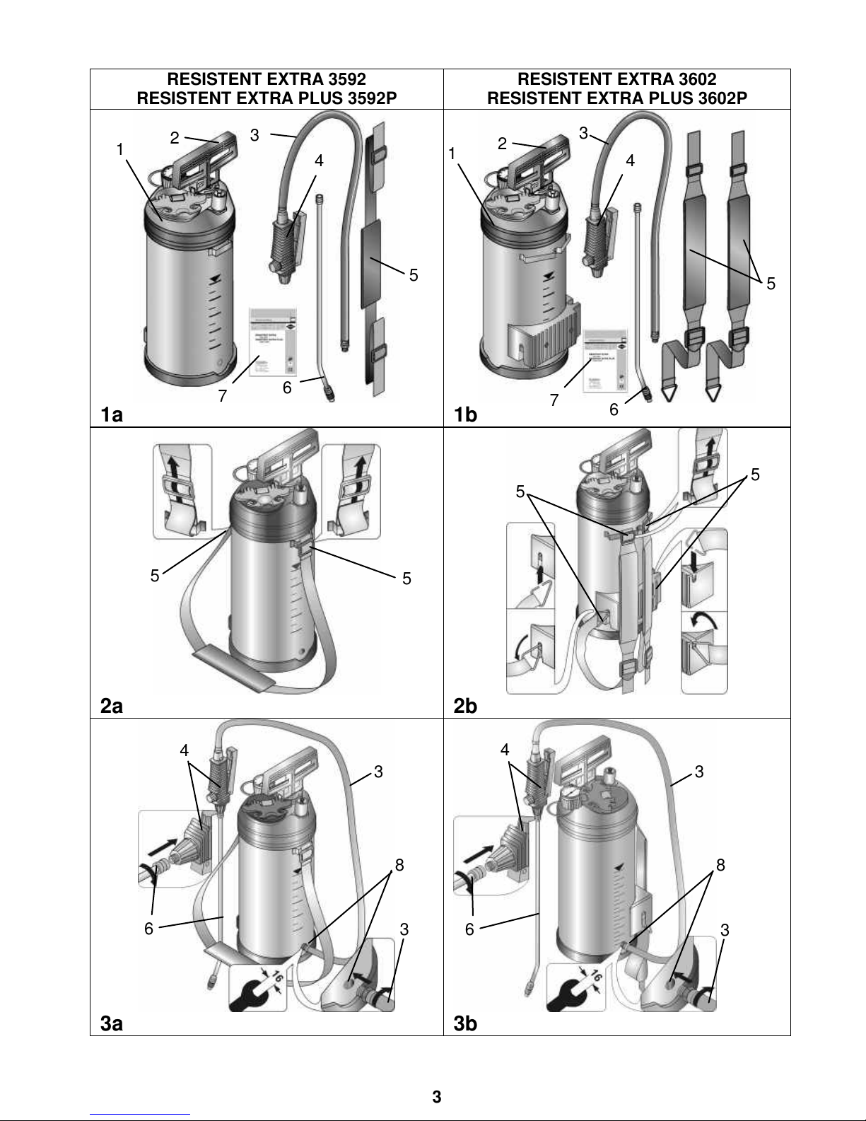
Tank [1] with pump [2], pressure hose [3] with shut-off valve [4], carrying strap [5], spray
lance with nozzle [6], instructions for use [7] (Figs. 1a and 1b)
You will find the illustrations referred to above in the front fold-out pages 3 – 5 of these
Instructions for Use.
Technical data
Device family
RESISTENT EXTRA
RESISTENT EXTRA PLUS
Type
3592
3602
3592P
3602P
Max. filling amount 5 l
Total contents approx. 8,75 l
Max. spraying pressure 6 bar (87 psi)
Max. operating temperature
50 °C (130.00 °F)
Weight when empty approx. 4 kg
Material of tank Stainless steel 18/9
Where device is carried Shoulder Back Shoulder Back
Technical residual quantity
0.03 l
Max. volume flow 0.78 l/min
Recoil force < 5 N
Table 1
Page 8
14
Assembly
1. Fasten the carrying strap [5] on the tank [1]. (Figs. 2a + 2b)
2. Screw the pressure hose [3] securely into the outlet opening [8] with a size 16 (metric)
wrench. (Figs. 3a + 3b)
3. Screw the spray lance [6] onto the shut-off valve [4]. (Figs. 3a + 3b)
4. Close the cover (→ chapter entitled "Preparation", Points 6 - 7, Fig. 7)
Checks
Visual inspection: Are the tank [1], pump [2], pressure hose [3] with shut-off valve
[4], pressure gage [15] and spray lance [6] undamaged? (Figs. 1, 9)
Pay special attention to the connections between the tank – pressure hose and the pressure
hose – shut-off valve and to the condition of the pump thread and pressure hose.
No leaks: Pump up the empty device to 2 bar.
► The pressure must not decrease more than 0.5 bar within 30 minutes.
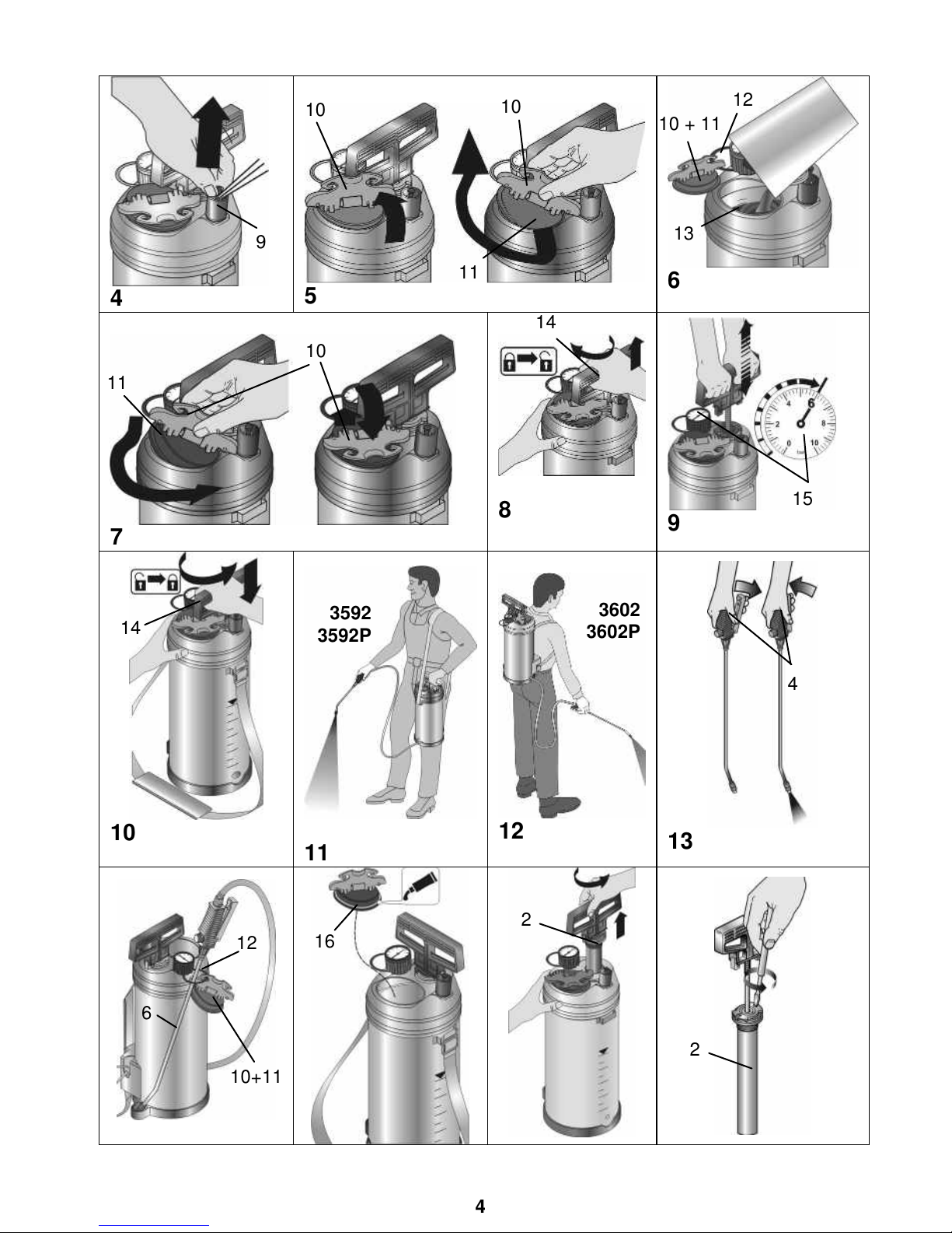
Function: Pull the red button on the safety valve [9]. (Fig. 4)
► The pressure must dissipate.
Activate the shut-off valve [4]. (Fig. 13)
► The shut-off valve must open and close.
Making preparations
Observe the instructions in the section entitled "Safety".
1. Pull up the red button on the safety valve [9] until all excess pressure is released from
the tank. (Fig. 4)
2. Raise the locking cap [10], tilt the cover [11], screw it in a clockwise direction and take
out of the filling opening. (Fig. 5)
3. Hook the cover [10+11] onto the spray lance holder [12]. (Fig. 6)
We recommend you mix the spraying liquid in the device or premix it in an external tank:
Fill to 1/3 with water, pour in the spraying agent, and then add more water until full.
4. Add the spraying liquid to the tank. (Fig. 6)
5. Check the filling height on the scale stamped on the tank [13]. (Fig. 6)
6. Insert the tilted cover [12] into the filling opening and rotate the cover in a counter-
clockwise direction. (Fig. 7)
7. Tighten the cover in the tank upwards onto the filling opening and fold down the locking
cap [10]. (Fig. 7)
► Filling opening is sealed. (Fig. 7)
8. Press the pump handle [14] down and turn it clockwise.
► The pump handle is unlocked. (Fig. 8)
9. Create the desired pressure (→ Table 2, next page) in the tank (Fig. 9).
The maximum pressure should not exceed 6 bar (red line on the pressure gauge [15],
Fig. 9). If the maximum pressure is exceeded, the safety valve will engage and release
the excess pressure.
10. Press the pump handle [14] down and turn it counterclockwise.
► The pump handle is locked in place. (Fig. 10)
Page 9
15
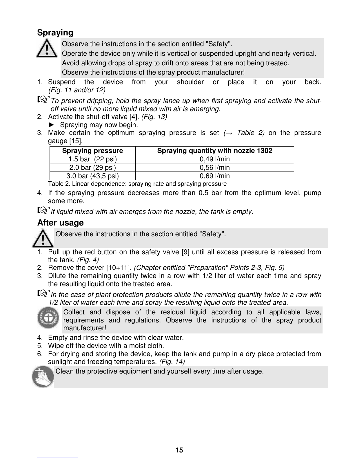
Spraying
Observe the instructions in the section entitled "Safety".
Operate the device only while it is vertical or suspended upright and nearly vertical.
Avoid allowing drops of spray to drift onto areas that are not being treated.
Observe the instructions of the spray product manufacturer!
1. Suspend the device from your shoulder or place it on your back.
(Fig. 11 and/or 12)
To prevent dripping, hold the spray lance up when first spraying and activate the shut-
off valve until no more liquid mixed with air is emerging.
2. Activate the shut-off valve [4]. (Fig. 13)
► Spraying may now begin.
3. Make certain the optimum spraying pressure is set (→ Table 2) on the pressure
gauge [15].
Spraying pressure
Spraying quantity with nozzle 1302
1.5 bar (22 psi) 0,49 l/min
2.0 bar (29 psi) 0,56 l/min
3.0 bar (43,5 psi) 0,69 l/min
Table 2. Linear dependence: spraying rate and spraying pressure
4. If the spraying pressure decreases more than 0.5 bar from the optimum level, pump
some more.
If liquid mixed with air emerges from the nozzle, the tank is empty.
After usage
Observe the instructions in the section entitled "Safety".
1. Pull up the red button on the safety valve [9] until all excess pressure is released from
the tank. (Fig. 4)
2. Remove the cover [10+11]. (Chapter entitled "Preparation" Points 2-3, Fig. 5)
3. Dilute the remaining quantity twice in a row with 1/2 liter of water each time and spray
the resulting liquid onto the treated area.
In the case of plant protection products dilute the remaining quantity twice in a row with
1/2 liter of water each time and spray the resulting liquid onto the treated area.
Collect and dispose of the residual liquid according to all applicable laws,
requirements and regulations. Observe the instructions of the spray product
manufacturer!
4. Empty and rinse the device with clear water.
5. Wipe off the device with a moist cloth.
6. For drying and storing the device, keep the tank and pump in a dry place protected from
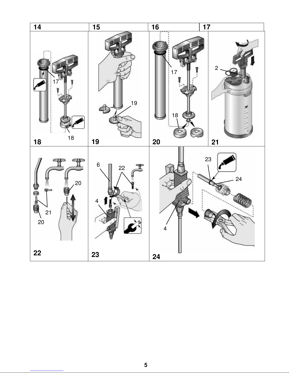
sunlight and freezing temperatures. (Fig. 14)
Clean the protective equipment and yourself every time after usage.
Page 10
16
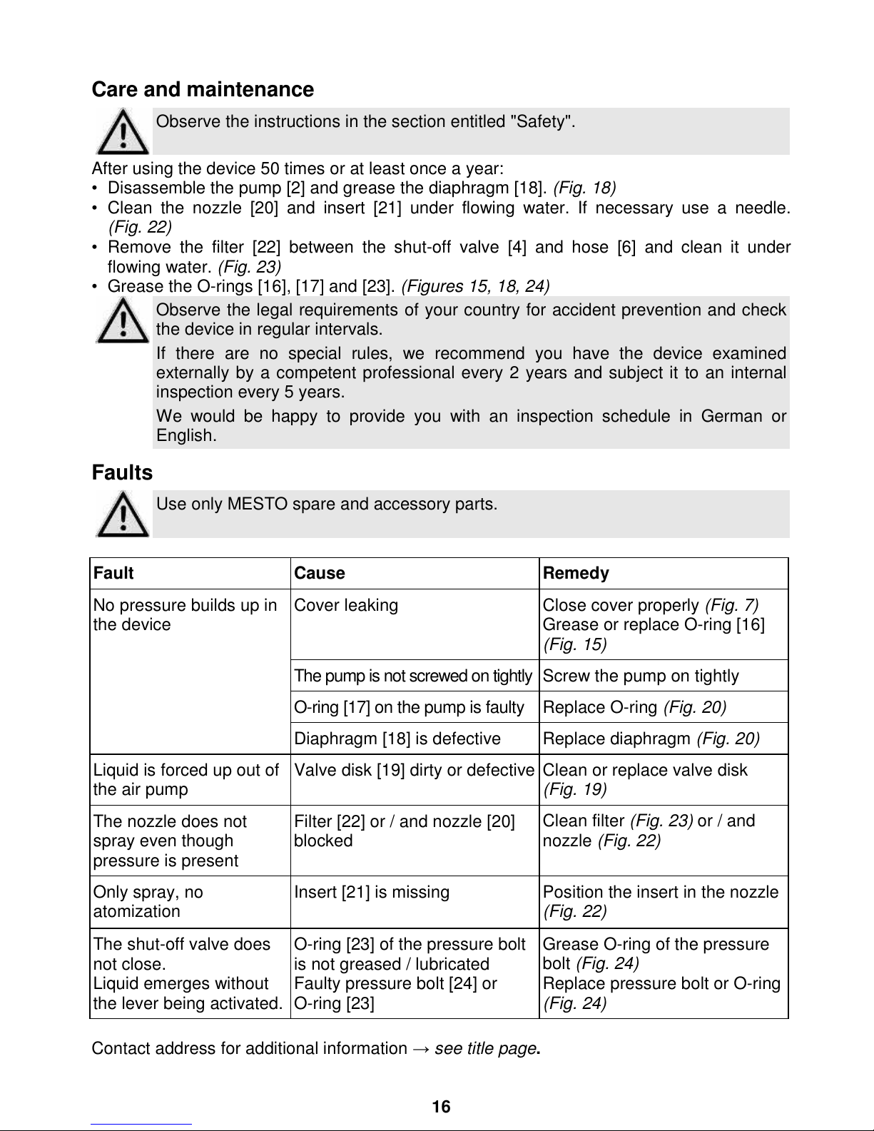
Care and maintenance
Observe the instructions in the section entitled "Safety".
After using the device 50 times or at least once a year:
• Disassemble the pump [2] and grease the diaphragm [18]. (Fig. 18)
• Clean the nozzle [20] and insert [21] under flowing water. If necessary use a needle.
(Fig. 22)
• Remove the filter [22] between the shut-off valve [4] and hose [6] and clean it under
flowing water. (Fig. 23)
• Grease the O-rings [16], [17] and [23]. (Figures 15, 18, 24)
Observe the legal requirements of your country for accident prevention and check
the device in regular intervals.
If there are no special rules, we recommend you ha
ve the device examined
externally by a competent professional every 2 years and subject it to an internal
inspection every 5 years.
We would be happy to provide you with an inspection schedule in German or
English.
Faults
Use only MESTO spare and accessory parts.
Fault
Cause
Remedy
No pressure builds up in
the device
Cover leaking
Close cover properly (Fig. 7)
Grease or replace O-ring [16]
(Fig. 15)
The pump is not screwed on tightly Screw the pump on tightly
O-ring [17] on the pump is faulty
Replace O-ring (Fig. 20)
Diaphragm [18] is defective
Replace diaphragm (Fig. 20)
Liquid is forced up out of
the air pump
Valve disk [19] dirty or defective Clean or replace valve disk
(Fig. 19)
The nozzle does not
spray even though
pressure is present
Filter [22] or / and nozzle [20]
blocked
Clean filter (Fig. 23) or / and
nozzle (Fig. 22)
Only spray, no
atomization
Insert [21] is missing Position the insert in the nozzle
(Fig. 22)
The shut-off valve does
not close.
Liquid emerges without
the lever being activated.
O-ring [23] of the pressure bolt
is not greased / lubricated
Faulty pressure bolt [24] or
O-ring [23]
Grease O-ring of the pressure
bolt (Fig. 24)
Replace pressure bolt or O-ring
(Fig. 24)
Contact address for additional information → see title page.
Page 11
17
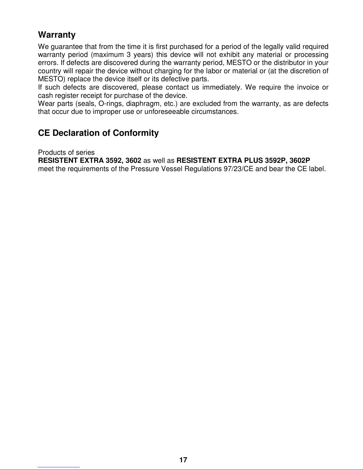
Warranty
We guarantee that from the time it is first purchased for a period of the legally valid required
warranty period (maximum 3 years) this device will not exhibit any material or processing
errors. If defects are discovered during the warranty period, MESTO or the distributor in your
country will repair the device without charging for the labor or material or (at the discretion of
MESTO) replace the device itself or its defective parts.
If such defects are discovered, please contact us immediately. We require the invoice or
cash register receipt for purchase of the device.
Wear parts (seals, O-rings, diaphragm, etc.) are excluded from the warranty, as are defects
that occur due to improper use or unforeseeable circumstances.
CE Declaration of Conformity
Products of series
RESISTENT EXTRA 3592, 3602 as well as RESISTENT EXTRA PLUS 3592P, 3602P
meet the requirements of the Pressure Vessel Regulations 97/23/CE and bear the CE label.
 Loading...