

Page 1
8LE-D23_BA_E
20.03.2015
1
/
58
OPERATING INSTRUCTION
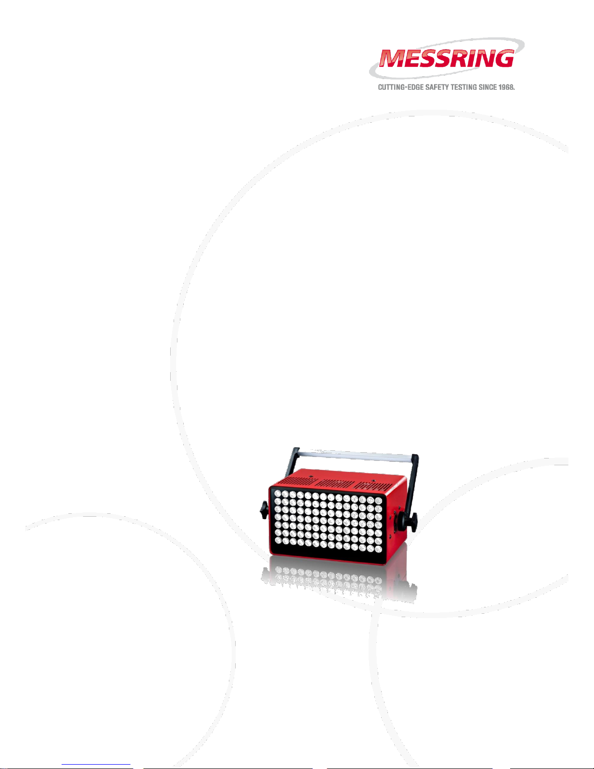
M=LIGHT LED, 1000W 8LE-D23
Contents
Chapter 1 About this Operating Instruction 2
Chapter 2 Health and Safety 5
Chapter 3 System Description 9
Chapter 4 Setup and Functioning 12
Chapter 5 Software 20
Chapter 6 Maintenance 44
Chapter 7 Technical Data 50
Chapter 8 Handling 52
Chapter 9 Special Accessories 57
Effective from Serial Number
15-00000
Effective from Software Release Number
2.0.0
Page 2

Meaning of this Operating Instruction
About this Operating Instruction
2
/
58
20.03.2015
8LE-D23_BA_E
Chapter 1 About this Operating Instruction
Contents
1.1. Meaning of this Operating Instruction 2
1.2. Description of Signs and Symbols 3
1.2.1. Warnings 3
1.2.2. Description of More Signs and Symbols 4
1.2.3. Contact 4
Property Rights According to ISO 16016
The content of this operating instruction is our intellectual property. We ask for your understanding,
that we cannot allow the transmission in whole or in part of this document to a third party,
especially to our competitors.
1.1. Meaning of this Operating Instruction
The operating instruction is part of your product. Consequently, you must keep this operating
instruction so that it is easily accessible for the operating personnel at all times.
When selling or leaving the product to third parties, the operating instruction must be handed over
to the new owner or user. Immediately replace the operating instruction if it is lost or incomplete. In
this case, contact MESSRING Systembau MSG GmbH.
Together with this operating instruction, you shall receive documents of third party manufacturers,
if necessary. Also familiarize yourself with these instructions and read the safety instructions and
warnings contained therein.
For your own safety, observe all safety instructions and warnings in chapter 2 of this operating
instruction. Also observe the warnings and safety instructions on the individual components and
activities in the other chapters.
Page 3
About this Operating Instruction
Description of Signs and Symbols
8LE-D23_BA_E
20.03.2015
3
/
58
1.2. Description of Signs and Symbols
1.2.1. Warnings
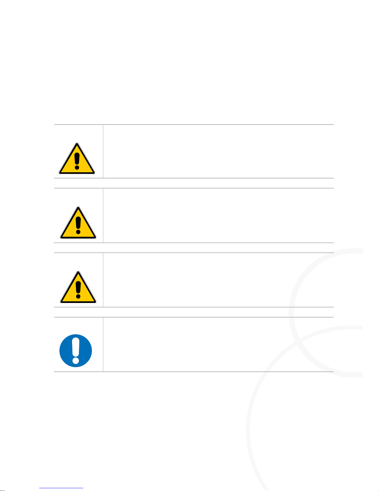
Depending on the scope of the consequences occurring in case of non-compliance with a warning
(death, irreversible or reversible injury, damage to property), there are 4 different risk levels. Each
risk level is marked with a certain signal word and a warning sign.
DANGER!
Refers to a dangerous situation which will lead to death or severe injury
if it is not avoided.
irreversible
WARNING!
Refers to a dangerous situation which may lead to death or severe injury
if it is not avoided.
irreversible
CAUTION!
Refers to a dangerous situation which may lead to minor or moderately
severe injury if it is not avoided.
reversible
NOTICE!
Damage to property
Page 4
Description of Signs and Symbols
About this Operating Instruction
4
/
58
20.03.2015
8LE-D23_BA_E
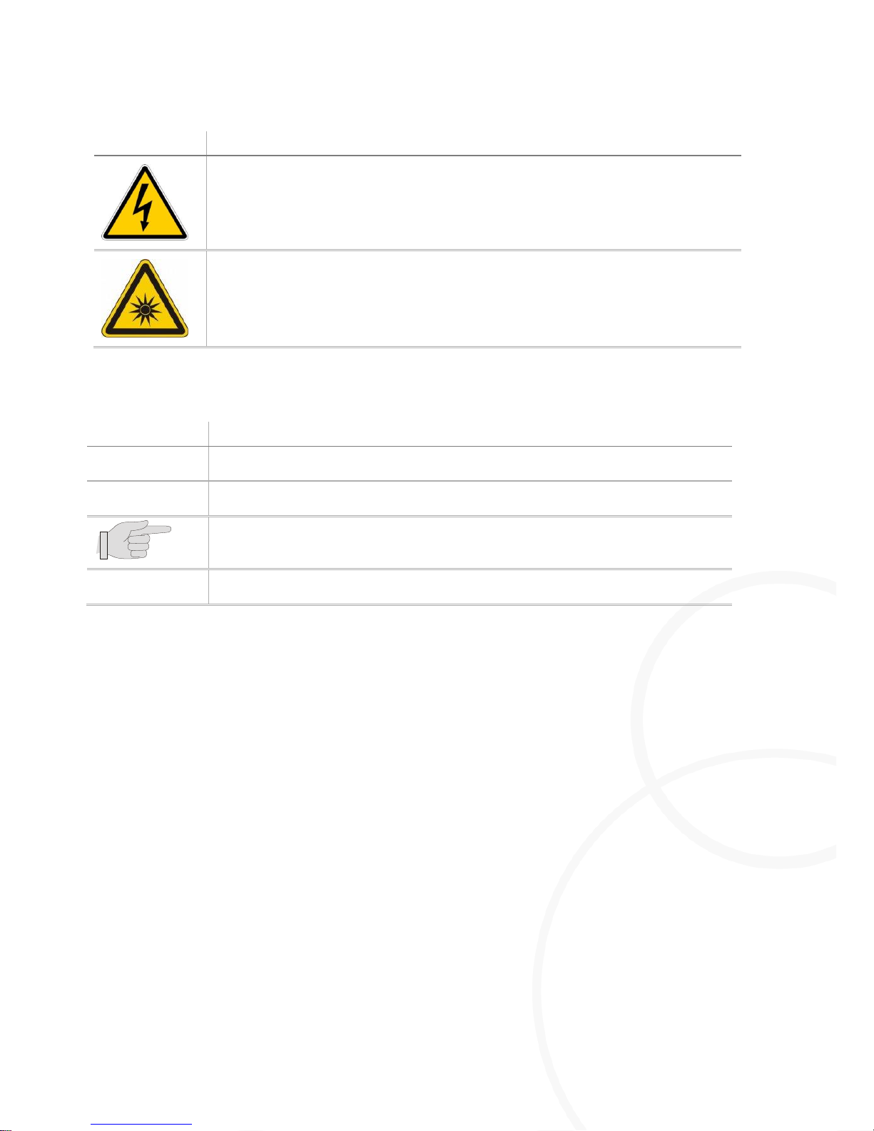
Warning sign
Meaning
Hazard due to electric voltage
Hazard due to optical radiation
1.2.2. Description of More Signs and Symbols
Symbol
Meaning
…
Step.
Result of a sequence of actions.
Hint / additional information.
New test
Element of the CrashSoft user interface or labeling of an operating element.
1.2.3. Contact
MESSRING Systembau MSG GmbH
Robert-Stirling-Ring 1
82152 Krailling
Germany
Phone: +49 89 898139-0
Fax: +49 89 898139-924
Email: [email protected]
Page 5
Health and Safety
Introduction
8LE-D23_BA_E
20.03.2015
5
/
58
Chapter 2 Health and Safety
Contents
2.1. Introduction 5
2.1.1. Target Groups 5
2.1.2. Main Sources of Danger 6
2.2. Purpose 8
2.2.1. Intended Use 8
2.2.2. Warning of Misuse 8
2.1. Introduction
This chapter provides information on hazards which emanate from the LED
light. The safety instructions and warnings aim to avoid fatal accidents, severe
injuries and damage to property.
Carefully read and observe all instructions in this chapter.
Observe the safety instructions and warnings on the individual
components and activities in the following chapters.
Completely read this operating instruction before beginning with
operation or maintenance of the M=Light-LED.
Observe regional, national and company-internal standards, directives
and regulations.
2.1.1. Target Groups
The chapter Health and Safety contains information for the following groups of people:
I Operator of the equipment in which the M=Light-LED are integrated
I Operating personnel
I Maintenance personnel
Page 6
Introduction
Health and Safety
6
/
58
20.03.2015
8LE-D23_BA_E
2.1.2. Main Sources of Danger
DANGER!
Electric shock due to electric charge inside the housing.
Immediately after disconnection, the contacts of the mains plug may still carry
voltage for a short period.
Do NOT touch the contacts of the mains plug directly after switch-off.
DANGER!
Functional impairment of electrical devices due to electromagnetic
radiation.
Electromagnetic radiation emitted by the M=Light LED may impair proper
function of electromedical devices.
Keep a distance off the operating M=Light LED of at least 1 m if you
have a cardiac pacemaker, defibrillators or other electronic implants.
DANGER!
Striking of persons due to falling M=Light LED
M=Light LED falling from the crash lighting frame may strike persons dead.
The M=Light LED must be securely screw-fixed with the crash lighting
frame using an attachment screw of proper dimension.
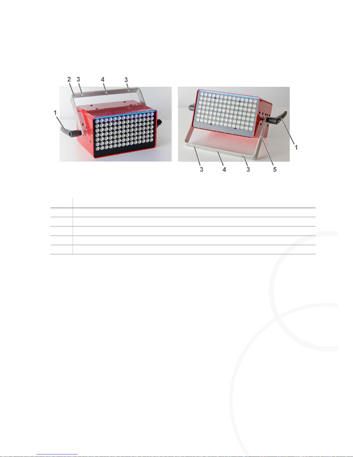
For screw-fixing the M=Light LED to the crash lighting frame, exclusively
use the attachment holes in the support bracket (Figure 10, Item 3 and 4,
page 19).
DANGER!
Electric shock and burning hazards at melting power cable.
Using the wrong power cable may lead to overheated power cable and thus to
the risk of burning hazards and electric shock due to melting power cable.
Only use the power cable delivered with the M=Light LED by
MESSRING.
Page 7
Health and Safety
Introduction
8LE-D23_BA_E
20.03.2015
7
/
58
CAUTION!
Damage to the eyes due to intensive irradiation of the eyes.
Chronic irradiation with light from the M=Light-LED may lead to damage of the
retina and cornea of the eyes.
Keep appropriate safety distance to the switched-on lamp.
When working at the switched-on lamp, wear protective goggles, e.g.
Infield, Terminator Orange UV-400 / Art.no.: 9380420
Do NOT stay within radiation range of the lamp longer than required.
Do NOT directly look into the beam of light.
Do NOT use M=Light LED as lighting for work spaces.
CAUTION!
Burns at hot surfaces
Burning hazard at the housing of the M=Light LED at temperatures of up to
100°C during operation at 120 V nominal voltage.
After operation at 120 V nominal voltage, leave the M=Light LED to
cool before touching it.
Before touching the M=Light LED, read the temperature in the bottom
line of the M=Light Control software.
Burning hazard at the shaft of the lamp suspension after longer operating
time.
Do NOT touch the shaft of the light suspension during operation or
shortly after switch-off of the light.
NOTICE!
Damage and breakdown of the M=Light LED
Overheating of the M=Light LED due to insufficient ventilation
Do NOT cover the ventilation slots.
NEVER position the M=Light LED directly on the housing.
Do NOT mount the M=Light LED in the flow range of the exhaust air of
other lights and lamps.
NOTICE!
Damage and breakdown of individual LEDs due to deposits of grease
or sweat.
Destruction of individual LEDs due to overheated grease or sweat residues.
Do NOT touch the LED array.
If required, rub the LEDs with a dry, clean cotton cloth.
Do NOT use cleaning agents.
Page 8

Purpose
Health and Safety
8
/
58
20.03.2015
8LE-D23_BA_E
2.2. Purpose
2.2.1. Intended Use
Stationary lighting of fast sequences that are recorded by means of high-speed cameras in the
indoor area. These may be e.g.:
I Vehicle and sled tests in crash test facilities.
I Airbag ignition and unfolding.
I Tests with partial car bodies or vehicle interior equipment
2.2.2. Warning of Misuse
Do NOT use M=Light-LED in outdoor areas.
Do NOT use M=Light-LED as working lighting for permanent work spaces.
Do NOT use M=Light-LED as on-board lighting.
Page 9

System Description
Purpose
8LE-D23_BA_E
20.03.2015
9
/
58
Chapter 3 System Description
Contents
3.1. Setup and Functioning 10
3.2. Main Components of M=Light LED 11
3.3. Special Properties and Performance Data 11
Page 10
Setup and Functioning
System Description
10
/
58
20.03.2015
8LE-D23_BA_E
3.1. Setup and Functioning
LED flood light for steady and pulsed operation.
Pulsed operation is synchronized with the high-speed camera. In pulsed operation, 80% more
lighting power can be output compared to steady operation. This is possible because the lighting is
only switched on when the camera requires light. The M=Light-LED can optionally be operated
manually or via the CAN-bus with the help of the software. In pulsed operation it is possible to
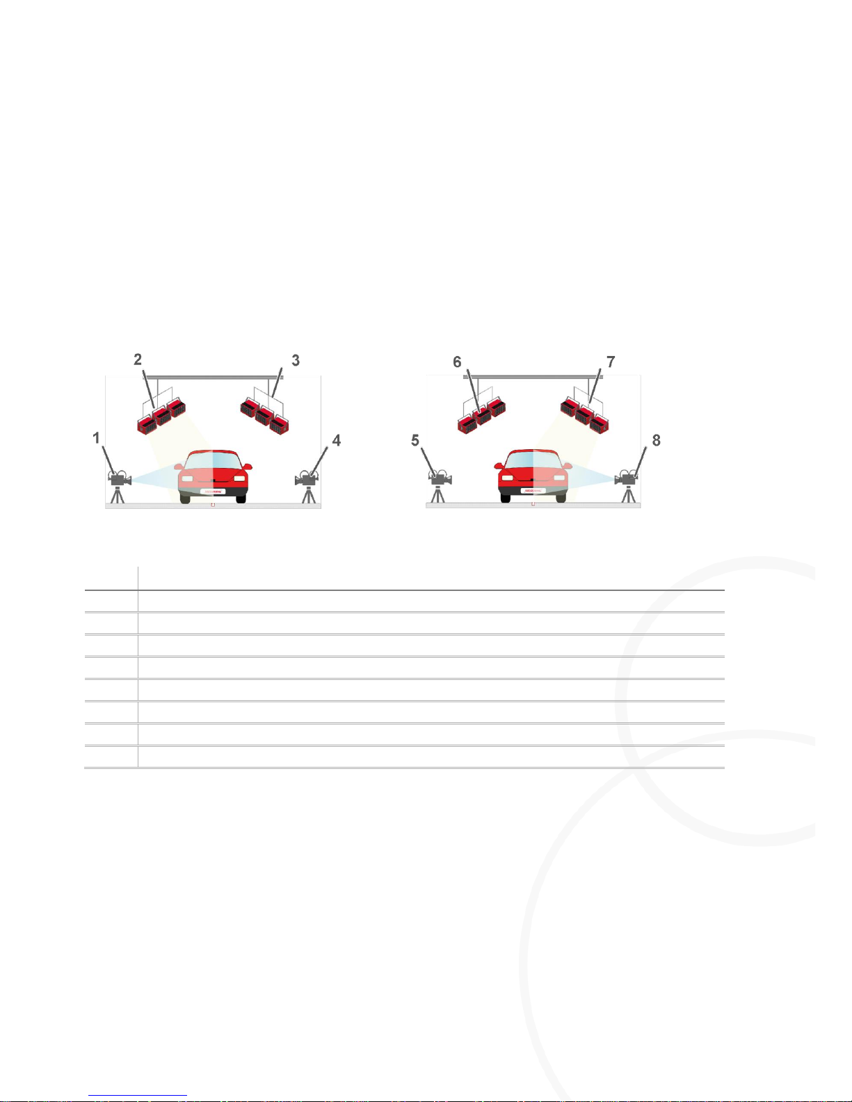
eliminate backlight effects due to control of separate M=Light-LED groups. For elimination of
backlight effects, only one camera synchronized with one M=Light-LED group is switched on
(Figure 1).
Figure 1: Synchronization in pulsed operation
Item:
Description
1
Camera 1 switched on
2
M=Light LED group 1 switched on
3
M=Light LED group 2 switched off
4
Camera 2 switched off
5
Camera 1 switched off
6
M=Light LED group 1 switched off
7
M=Light LED group 2 switched on
8
Camera 2 switched on
Page 11

System Description
Main Components of M=Light LED
8LE-D23_BA_E
20.03.2015
11
/
58
3.2. Main Components of M=Light LED
I LED array with status indication
I Aluminum housing
I Support bracket for one- and two-point attachment
I CAN-bus connections
I M=Light control software for control of the M=Light LED via CAN-bus
I CAN-bus interface for control of the CAN-bus via PC-USB connection (optional).
3.3. Special Properties and Performance Data
I No warm-up time required - ready for operation directly after switch-on.
I Test object is NOT overheated by radiation of heat.
I Can be synchronized with camera shutter.
I CAN-bus-controlled
I Non-flickering and dimmable
I Stable aluminum housing
I Customized lighting angles
I Service life of the LEDs more than 50,000 hours
I Delay between trigger input and light flash approx 10 µs
Page 12

Special Properties and Performance Data
Setup and Functioning
12
/
58
20.03.2015
8LE-D23_BA_E
Chapter 4 Setup and Functioning
Contents
4.1. LED Array 13
4.2. Rear Side of the Housing 15
4.2.1. Connecting / Disconnecting Voltage Supply 15
4.2.2. Establishing Signal Connections 16
4.2.3. Contact Assignment of CAN-Bus Connections 18
4.3. Support Bracket 19
Page 13
Setup and Functioning
LED Array
8LE-D23_BA_E
20.03.2015
13
/
58
4.1. LED Array
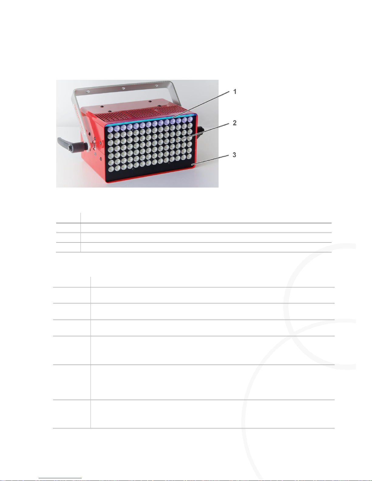
Figure 2: LED array with status indication
Item:
Description
1
Status indication in the LED array
2
LEDs
3
Front plate
The status display in the LED Array indicates the major operating conditions of the M=Light-LED
Indication:
Operating condition
Permanent
green
M=Light-LED is ready for operation and can be switched on (temperature ≤ 30°C).
Permanent
blue
M=Light-LED is ready for operation and can be switched on (temperature ≥ 30°C; ≤ 90°C).
Flashing
blue
The maintenance counter was scanned by the Maintenance command. After the last
maintenance the M=Light LED has been switched on for more than 150 hours
Permanent
yellow
M=Light LED has heated up so much that the ventilators are switched on. Operation of the
M=Light LED can be continued without further restrictions.
I The current temperature of the M=Light LED is > 40°C
Permanent
red
M=Light-LED is in critical condition. M=Light-LED can be operated without the M=Light being
damaged further due to operation. However, operation is not recommended since the lamp
might switch off automatically after a short period (temperature >100°C).
I The current temperature of the M=Light LED is > 85°C
Flashing
red
M=Light-LED is defective and has been switched off. This may be the result of the following
causes:
I At least one fan is defective.
Page 14
LED Array
Setup and Functioning
14
/
58
20.03.2015
8LE-D23_BA_E
I The electronic assembly for output control is damaged.
Off
M=Light-LED is either switched on, defective or is not supplied with operating voltage.
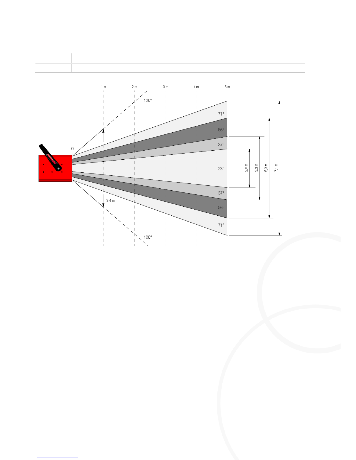
Figure 3: Lighting angles
The lighting angles are custom-specific, they can be identified via the M=Light Control software.
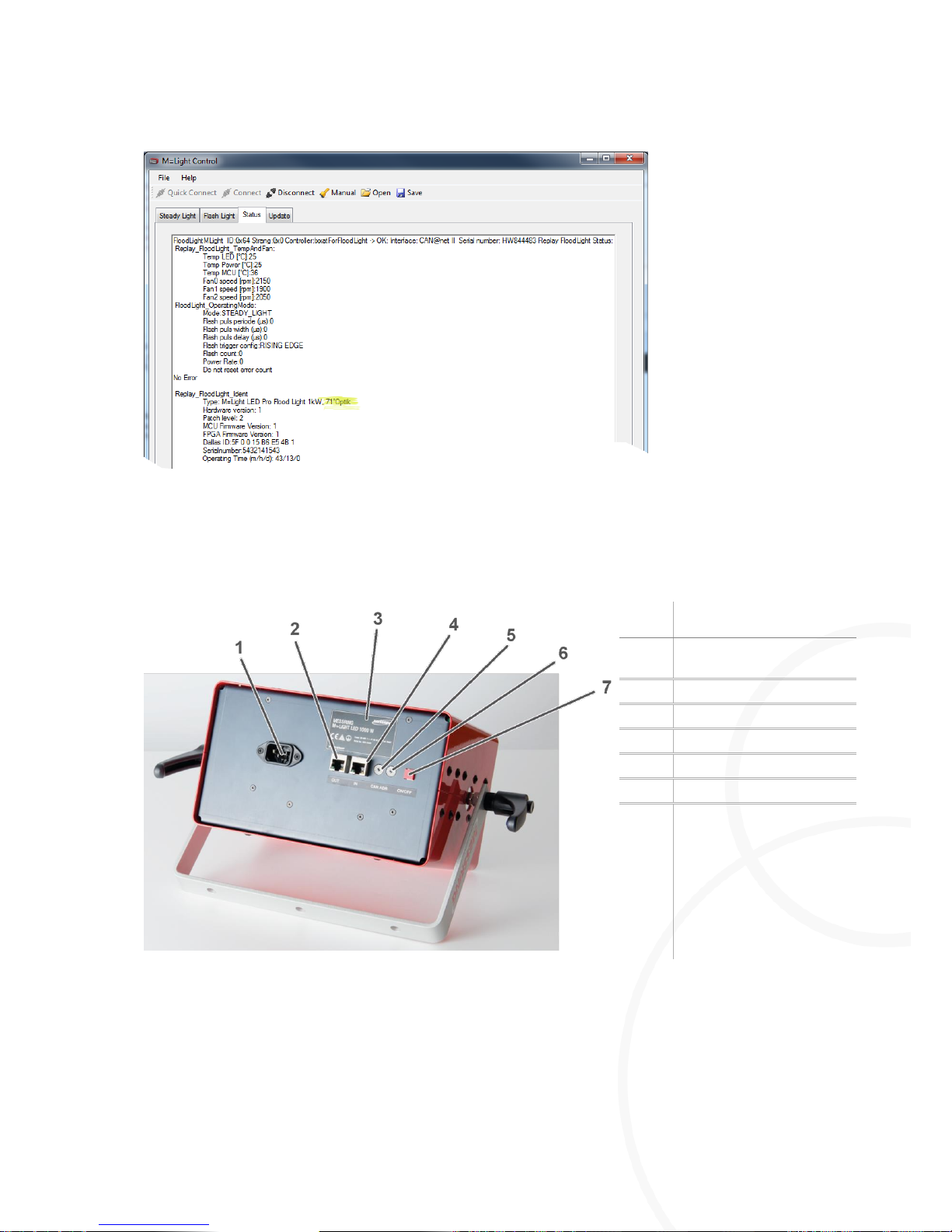
The angle set for the mounted LEDs is provided in the status display of the software (Figure 5):
Page 15
Setup and Functioning
Rear Side of the Housing
8LE-D23_BA_E
20.03.2015
15
/
58
Figure 4: Display of the lighting angle in the software
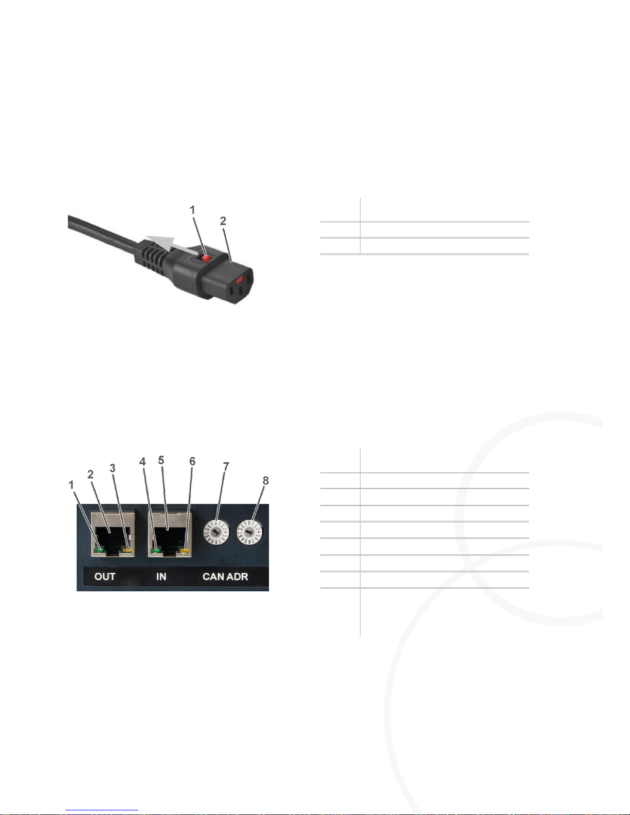
4.2. Rear Side of the Housing
Item:
Description
1
Voltage supply
connection
2
CAN-bus Out
3
Nameplate
4
CAN-bus In
5
CAN-bus address (MSB)
6
CAN-bus address (LSB)
7
On / Off switch for
manual operation.
Figure 5: Connections and control elements on the rear side
4.2.1. Connecting / Disconnecting Voltage Supply
Connecting Voltage Supply
Establish mains voltage via IEC-320 AC power cord set (Figure 5, Item 1).
Page 16
Rear Side of the Housing
Setup and Functioning
16
/
58
20.03.2015
8LE-D23_BA_E
Take into account the power rating (section 7.2, page 50).
Take into account the limit values for frequencies (section 7.2, page 50).
Do NOT supply components via multiple socket outlets.
The M=Light LED is now supplied with operating voltage.
Disconnecting Voltage Supply
Item:
Description
1
Locking device
2
Male connector
Figure 6: AC power cord set with IEC-lock
Pull back the lock at the female connector.
Pull out the male connector.
The M=Light LED is now disconnected from voltage supply.
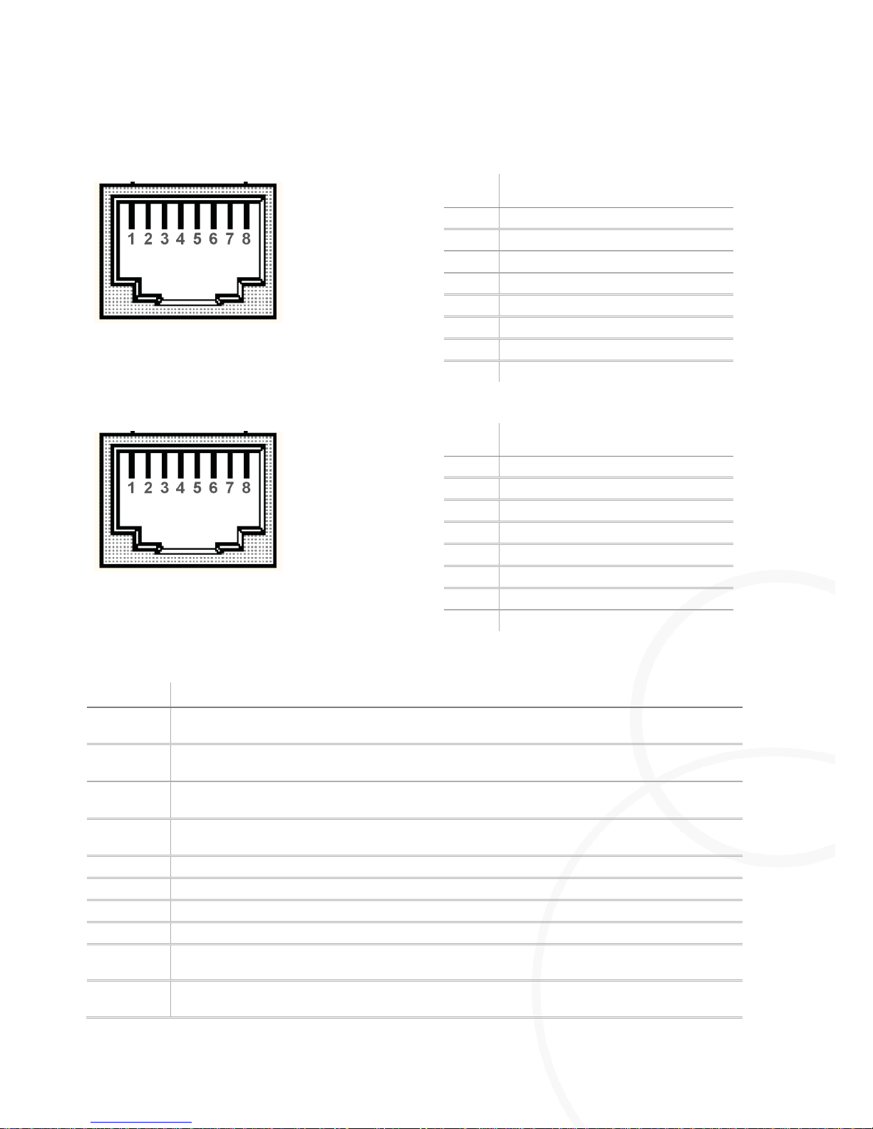
4.2.2. Establishing Signal Connections
Item:
Description
1
LED +9V I/O
2
CAN-bus OUT (Figure 9, page 18)
3
LED CAN-bus TX active
4
LED V I/O external
5
CAN-bus IN (Figure 8, page 18)
6
LED CAN-bus RX active
7
CAN-bus address (MSB)
8
CAN-bus address (LSB)
Figure 7: CAN-bus on the rear side of the housing
Connect the CAN-bus interface with the control PC.
Connect the RJ45 input IN of the first M=Light-LED with the CAN-bus interface.
Connect the RJ45 output OUT of the first M=Light-LED with the input IN of the second M=Light-
LED.
Page 17

Setup and Functioning
Rear Side of the Housing
8LE-D23_BA_E
20.03.2015
17
/
58
Connect additional M=Light-LED accordingly.
For connection of the M=Light-LEDs, use patch cables according to CAT5 EIA/TIA-568 or
higher.
Specify a unique CAN-bus address for every M=Light LED in the same CAN-bus line.
Now, the signal connections have been completely established. The CAN-bus and Flash-bus
are automatically terminated by the internal terminating resistor of the M=Light LED last
connected.
Page 18
Rear Side of the Housing
Setup and Functioning
18
/
58
20.03.2015
8LE-D23_BA_E
4.2.3. Contact Assignment of CAN-Bus Connections
Item:
Signal
1
Flash L
2
Flash H
3
GND out
4
+9V out
5
GND in
6
+9V in
7
CAN L
8
CAN H
Figure 8: Contact assignment of CAN-bus IN
Item:
Signal
1
Flash L
2
Flash H
3
Term -
4
Term +
5
GND
6
+9V out
7
CAN L
8
CAN H
Figure 9: Contact assignment of CAN-bus OUT
Item:
Description
Flash L
Input for physical CAN-bus signal for switching the M=Light LED on and off. Also used as output in
Master mode.
Flash H
Input for physical CAN-bus signal for switching the M=Light LED on and off. Also used as output in
Master mode.
GND out
Ground connection to previous M=Light LED (Term-) for switch-off of the terminating resistor at the
Flash and CAN output.
+9V D I/O
9V output connection to previous M=Light LED (Term+) for switch-off of the terminating resistor at
the Flash and CAN output.
GND
Ground connection for 9V output
+9V out
9V output
CAN L
Input for physical CAN-bus signal for parameterization of the M=Light LED.
CAN H
Input for physical CAN-bus signal for parameterization of the M=Light LED.
Term -
Input connection from next M=Light LED for switch-off of the terminating resistor at the Flash and
CAN output.
Term +
Input connection from next M=Light LED for switch-off of the terminating resistor at the Flash and
CAN output.
Page 19
Setup and Functioning
Support Bracket
8LE-D23_BA_E
20.03.2015
19
/
58
4.3. Support Bracket
Figure 10: Support bracket
Item:
Description
1
Fixing screw for support bracket
2
Support bracket for attachment of M=Light LED
3
Outer attachment holes, 2 units, ∅ 10mm
4
Inner attachment hole, ∅ 10mm
5
Support bracket as base for M=Light LED
Positioning the Support Bracket
Open both fixing screws so much that the support bracket can be turned under light resistance.
Turn the support bracket in position.
Tighten both fixing screws.
Now, the support bracket is in the intended position.
Page 20

Support Bracket
Software
20
/
58
20.03.2015
8LE-D23_BA_E
Chapter 5 Software
Contents
5.1. What is the Purpose of M=Light Control Software? 21
5.2. Installation of the M=Light Control Software 21
5.2.1. System Prerequisites 21
5.2.2. Installation Process 21
5.3. Operating the Software 22
Page 21

Software
What is the Purpose of M=Light Control Software?
8LE-D23_BA_E
20.03.2015
21
/
58
5.1. What is the Purpose of M=Light Control Software?
The software is used for control and parameterization of the M=Light LED. All parameters that
have been set and adjusted by means of M=Light-Control will be maintained after disconnection of
the CAN-bus line. Saving of the parameterization in the M=Light LED is non-volatile and data is
maintained in the M=Light LED even if it is disconnected from the voltage supply.
5.2. Installation of the M=Light Control Software
5.2.1. System Prerequisites
I PC with USB port
I Windows XP or Windows 7 operating system
I CAN-bus interface for USB port
5.2.2. Installation Process
Connect the data carrier supplied with the M=Light LED to the PC.
Run Setup.exe.
Select a language.
The installation routine at first guides you through installation of the MESSRING M=Light Control
software and subsequently through installation of the IXXAT MiniMon driver for the CAN-bus
interface.
Page 22
Operating the Software
Software
22
/
58
20.03.2015
8LE-D23_BA_E
5.3. Operating the Software
5.3.1. User Interface and Status Indicator without M=Light LED
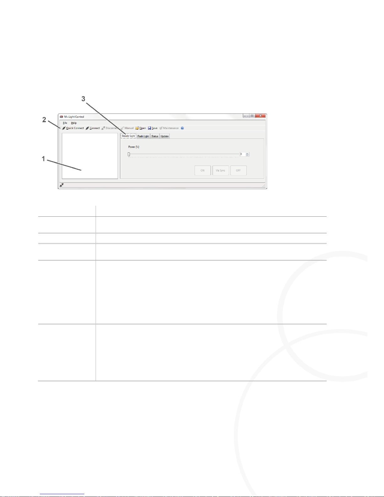
Figure 11: User interface and status indicator without M=Light LED connected
Designation
Description
1
In the M=Light Explorer you can view the M=Light LEDs connected with the software,
both individually and in groups.
2
Command line for all M=Light LEDs connected.
3
Tabs for operation and status indication of M=Light LEDs that are marked in the
M=Light Explorer.
Quick Connect
Connects the M=Light LEDs already detected during the previous application with the
software.
Use this process if the wiring, the CAN-Bus address of the M=Light LEDs or the
Groups.ini file has NOT been changed.
Press Quick Connect.
The M=Light LEDs already detected during the previous application are
connected with the software.
Connect
Scans the entire bus system (up to 255 M=Light LEDs).
Use this process if the wiring, the CAN-Bus address of the M=Light LEDs or the
Groups.ini file has been changed.
Press Connect.
The entire bus line is scanned and all M=Light LEDs are connected to the
software. This process may take a few minutes.
Page 23
Software
Operating the Software
8LE-D23_BA_E
20.03.2015
23
/
58
5.3.2. User Interface and Status Indicator with M=Light LED
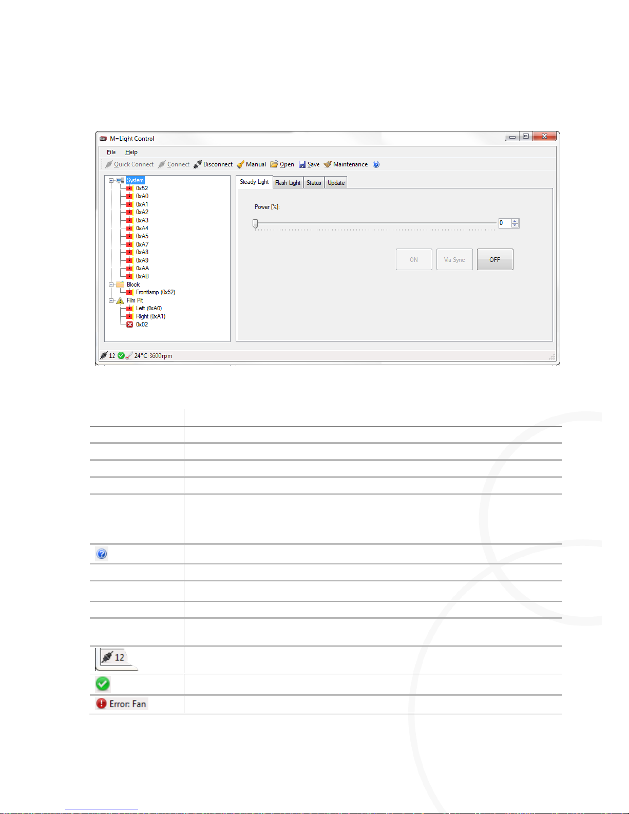
Figure 12: User interface and status indicator with M=Light LED connected
Designation
Description
Disconnect
Press Disconnect to disconnect all connected M=Light LEDs from the software
Manual
Manual operation of M=Light LEDs (section 8.3, page 54).
Open
Open the file in which the parameterization data is saved (*.led).
Save
Save the current parameterization data in a file (*.led).
Maintenance
Each M=Light LED is equipped with an integrated operating hours counter. The
Maintenance command queries the operating hour counter in all M=Light LEDs. If the
operating hour counter displays more than 150 hours, the status indicator of the
M=Light LED flashes blue (section 4.1, page 13).
Opens the operating instruction of the M=Light LED
Steady Light
Window for parameterization of steady light.
Flash Light
Window for parameterization of pulsed operation.
Status
Displays the status of the M=Light LED highlighted in the M=Light Explorer.
Update
Performs firmware or FPGA update. Only perform updates upon agreement with
MESSRING.
Indicates how many M=Light LEDs are connected via CAN-bus with the PC and thus
with the M=Light Control.
Status indication, M=light LED operational.
One or more fans have failed, M=Light LED was switched off.
Page 24
Operating the Software
Software
24
/
58
20.03.2015
8LE-D23_BA_E
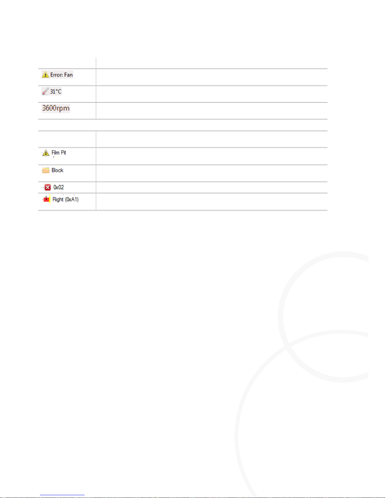
Designation
Description
One or more fans had failed, M=Light LED was switched off. The fans have been
remedied and are functional; M=Light LED can be switched back on.
The highest temperature value currently measured at the connected M=Light LEDs is
31°C.
The lowest fan speed value currently measured at the connected M=Light LEDs is
3,600 rpm.
M=Light LED Explorer
System
Shows all M=Light LEDs connected with the software, regardless of any group in
which the LEDs may also be included.
Group of M=Light LEDs with the name Film Pit , in which one or more M=Light LEDs
indicate an error.
Group of M=Light LEDs with the name Block , in which NO M=Light LED indicates an
error.
Individual M=Light LED with the address 0x02, which indicates an error.
Individual M=Light LED with the description Right and the address 0xA1, that does
NOT indicate an error.
Page 25
Software
Operating the Software
8LE-D23_BA_E
20.03.2015
25
/
58
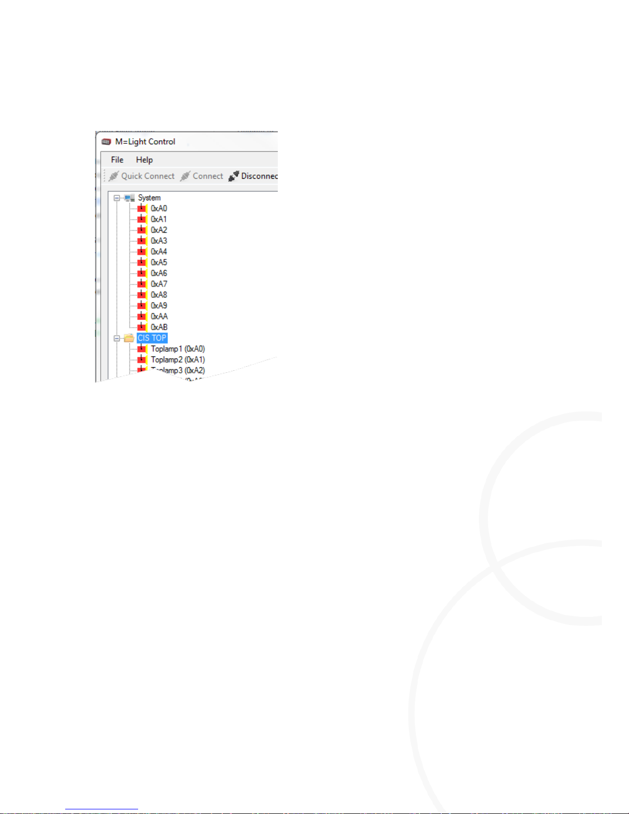
5.3.3. M=Light Explorer
Figure 13: M=Light Explorer
Options for highlighting the M=Light LED in the M=Light Explorer
I Highlight all M=Light LEDs connected (system)
I Highlight a group of M=Light LED (e.g.: CIS TOP)
I Highlight an individual M=Light LED (e.g.: Toplamp1 (0xA0))
Highlighting M=Light LEDs in M=Light Explorer
Highlight an M=Light LED, a group, or a system using the left mouse button.
The highlighted M=Light LED, group, or system is shaded blue (Figure 13).
You have highlighted the required M=Light LED and are now able to parameterize it, query its
status or perform an update.
Page 26
Operating the Software
Software
26
/
58
20.03.2015
8LE-D23_BA_E
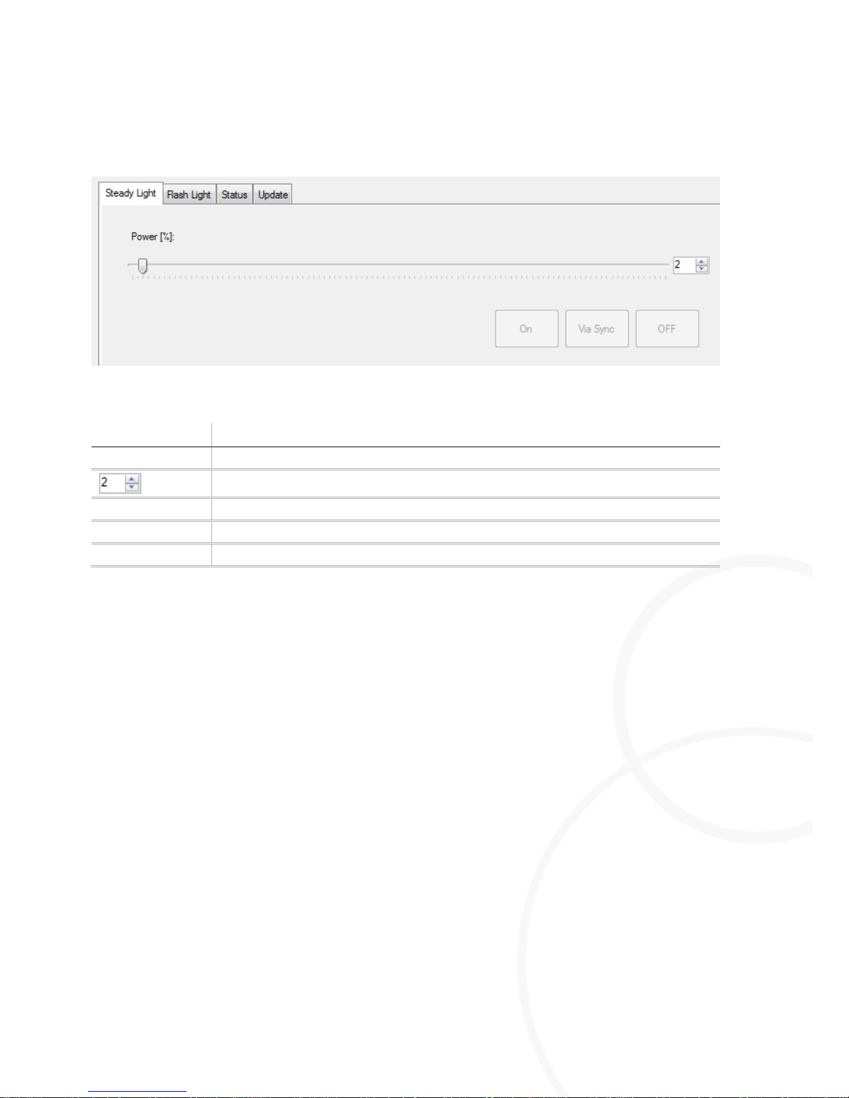
5.3.4. Parameterization of M=Light LED for Steady Light Operation
Figure 14: Steady light window
Designation
Description
Power [%]
Select the intensity of M=Light LED in %
Selected intensity in %.
ON
Switch on the M=Light LED at the selected intensity.
Via Sync
Permanent switch-on or switch-off of M=Light LED via input (Flash H / Flash L).
OFF
Permanent switch-off of M=LIGHT LED Pro.
Permanent Switch-on of M=LIGHT LED Pro.
Open the Steady Light window.
Highlighting M=Light LEDs in M=Light Explorer
Adjust the required intensity by the Power [%] slide control.
Press On.
The previously highlighted M=Light LED or group is switched on for permanent operation as
soon as voltage is supplied.
Changing the intensity of the M=Light LED in switched-on condition
Open the Steady Light window.
Highlighting M=Light LEDs in M=Light Explorer
Adjust the required intensity by the Power [%] slide control.
Press On.
The intensity of the previously highlighted M=Light LED or group is changed to the currently set
value.
Page 27

Software
Operating the Software
8LE-D23_BA_E
20.03.2015
27
/
58
Switch-on and off of M=Light LED via Trigger Line
Open the Steady Light window.
Adjust the required intensity by the Power [%] slide control.
Press Via Sync.
M=Light LED is switched on for permanent operation when the level at the input (Flash H /
Flash L) is changed from recessive to dominant. If the level falls from dominant to recessive,
the M=Light LED is switched off.
Permanent Switch-off of M=LIGHT LED Pro
Open the Steady Light window.
Press Off.
M=Light LED is permanently switched off and can only be switched on again upon change of
parameterization.
Page 28
Operating the Software
Software
28
/
58
20.03.2015
8LE-D23_BA_E
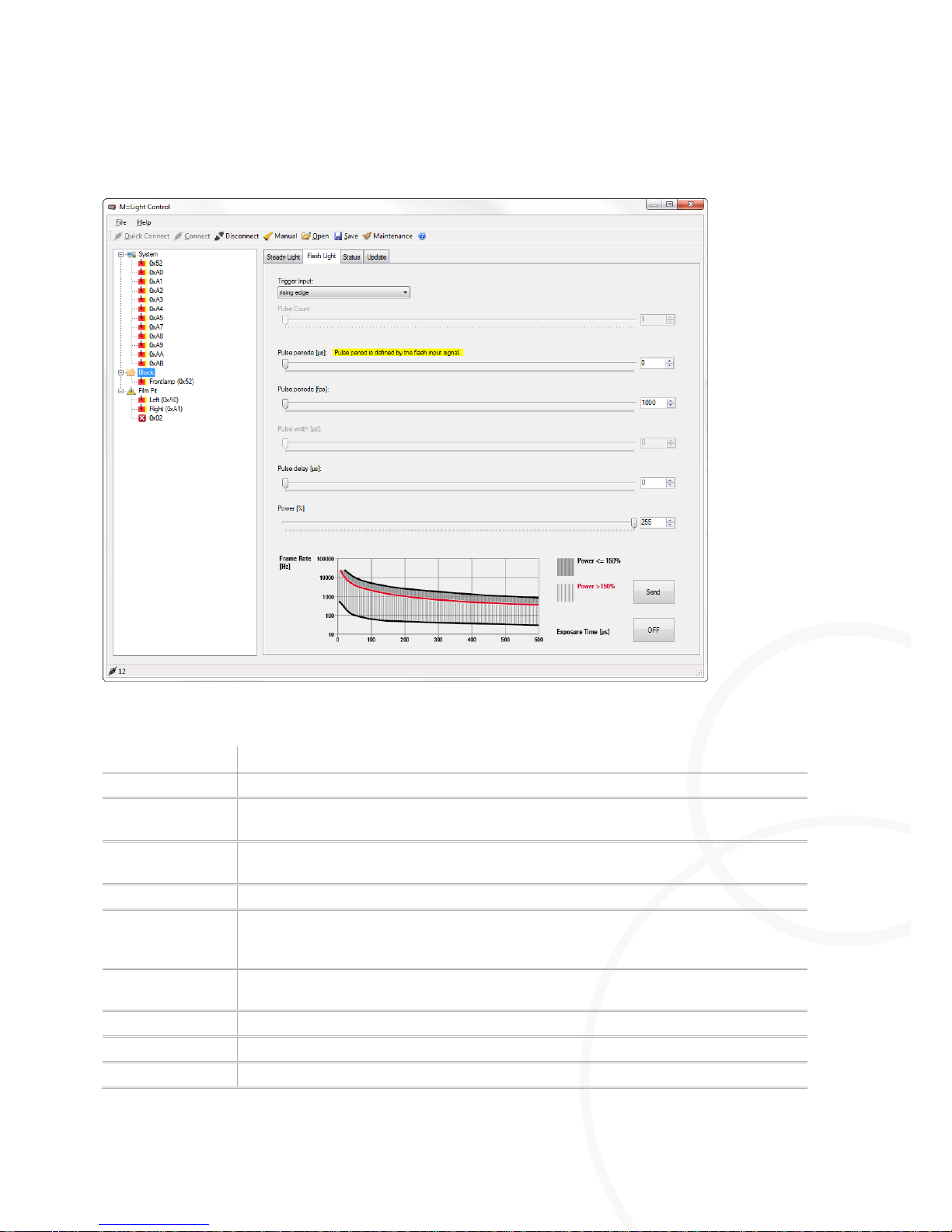
5.3.5. Parameterization of M=Light LED for Pulsed Operation
Figure 15: Flash light window
Designation
Description
Trigger input
Selects the input signal for the trigger (Figure 17, page 33).
Pulse Count
Number of periods per trigger event. In the Software (Mastermode) operating mode an
unlimited number of pulses is emitted if the value is set to 0.
Pulse period [µs]
Duration of a period (pulse + pause) in µs. If you set the value for Pulse periode to 0,
the Auto-Follow operating mode is switched on.
Pulse width [µs]
Duration of a pulse in µs (switch-on duration).
Pulse delay [µs]
Time delay by which the pulse is to be retarded in comparison with the trigger input
time. If for Pulse delay the parameterized value is 0, the delay between trigger event
and light flash is approx. 10µs.
Power [%]
Intensity with which M=Light LED is to be switched on as long as the pulse is active.
In pulsed operation, the intensity may be increased up to 255%.
Send
Transmit set parameters to M=Light LED.
Off
Switches all connected M=Light LEDs to power = 0%
Trigger
Theoretically possible pulse sequence at the trigger input for selected parameters.
Page 29
Software
Operating the Software
8LE-D23_BA_E
20.03.2015
29
/
58
Designation
Description
Trigger
Pulse period for the trigger input based on the selected parameters (Figure 18,
page 33).
LED Light
On / Off duration of the M=Light LED based on the assumed trigger pulse and
selected parameters (Figure 18, page 33)
Delay
Switch-on delay for selected parameters.
Width
Switch-on duration of M=Light LED for selected parameters.
Period
Switch-on / -off cycle of M=Light LED for selected parameters.
Page 30
Operating the Software
Software
30
/
58
20.03.2015
8LE-D23_BA_E
5.3.5.1. Auto-Follow Operating Mode
In the Auto-Follow operating mode, not only the switch-on pulse is adapted according to the Sync
signal from the camera system but also the values for Pulse period, Pulse width and Pulse delay.
Requirements for the Sync signal from the camera control:
I electrical signal at which the pulse duration and the frequency of the signal corresponds to the
exposure time.
I With the Auto-Follow selected for the M=Light LED, the duration of the switch-on pulses and the
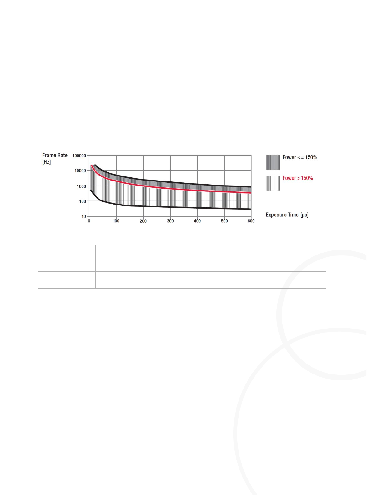
intensity set must comply with the diagram that is shown in the software (Figure 16).
Figure 16: Diagram, permissible Sync signal
Designation
Description
Black characteristic
curve
Maximum permissible limit values with a defined output of up to 150%.
Red characteristic
curve
Upper limit values with a defined output of more than 150%. In this scenario, the
lower limit values are identical to the limit values for <150%.
I Rough reference values for the permitted switch-on duration at common flash times:
With an intensity of <150%, set the switch-on duration at <50% of the period of used
frame rate (Pulse period / Pulse width ≤ 2/1).
With an intensity of >150%, set the switch-on duration at <20% of the period of used
frame rate (Pulse period / Pulse width ≤ 5/1).
Page 31

Software
Operating the Software
8LE-D23_BA_E
20.03.2015
31
/
58
5.3.5.2. Error message in the Auto-Follow operating mode
Error in flash signal
Error cause:
I The Sync signal emitted by the camera system does NOT comply with the permitted switch-on
duration of the M=Light LED at the pre-selected intensity.
Consequence of the error:
I Triggered switch-on processes are not performed, which may result in bright > dark frame
sequences in the shots.
Preventing errors:
Check if the Sync signal emitted by the camera system corresponds to the permitted switch-on
duration of the M=Light LED at the pre-selected intensity.
Adjust the intensity of the M=Light LED at the Power slide control in the Flash Light window.
Adjust the frame rate of the camera system.
Adjust the exposure duration of the camera system.
You have adjusted the input signal to the physical limits of the M=Light LED and are now able
to produce high-quality shots with good exposure.
Switching on the Auto-Follow operating mode:
Highlight the required M=Light LED.
Select the trigger input.
Slide the Pulse period slide control to 0.
Adjust the required intensity for the switch-on duration between 1 and 255% by means of the
Power slide control.
You have switched on the Auto-Follow operating mode. The M=Light LEDs are controlled at the
selected intensity in accordance with the input signal supplied by the camera system. In the
section Pulse period the following message is shown, highlighted yellow: Pulse period is defined by
the flash input signal
Page 32

Operating the Software
Software
32
/
58
20.03.2015
8LE-D23_BA_E
5.3.5.3. Trigger-Follow Operating Mode
The Trigger-Follow operating mode only serves for applying the switch-on pulse of the control signal
from the camera system.
Switching on the Trigger-Follow operating mode:
Highlight the required M=Light LED.
Select Trigger Input.
Slide the Pulse period slide control to > 0.
Adjust the required number of pulses per trigger process.
Select the required period duration (Pulse period
[µs]
) or the required frame rate (Pulse period
[fps]
).
Adjust the required pulse duration (Pulse width
[µs]
).
Adjust the required pulse delay (Pulse delay
[µs]
).
Adjust the required intensity for the switch-on duration between 1 and 255% (Power).
Press Send.
You have switched on the Trigger-Follow operating mode. The highlighted M=Light LEDs are
now controlled in accordance with the selected parameters, depending on the corresponding
trigger signal pending at the input of the M=Light LED.
Page 33
Software
Operating the Software
8LE-D23_BA_E
20.03.2015
33
/
58
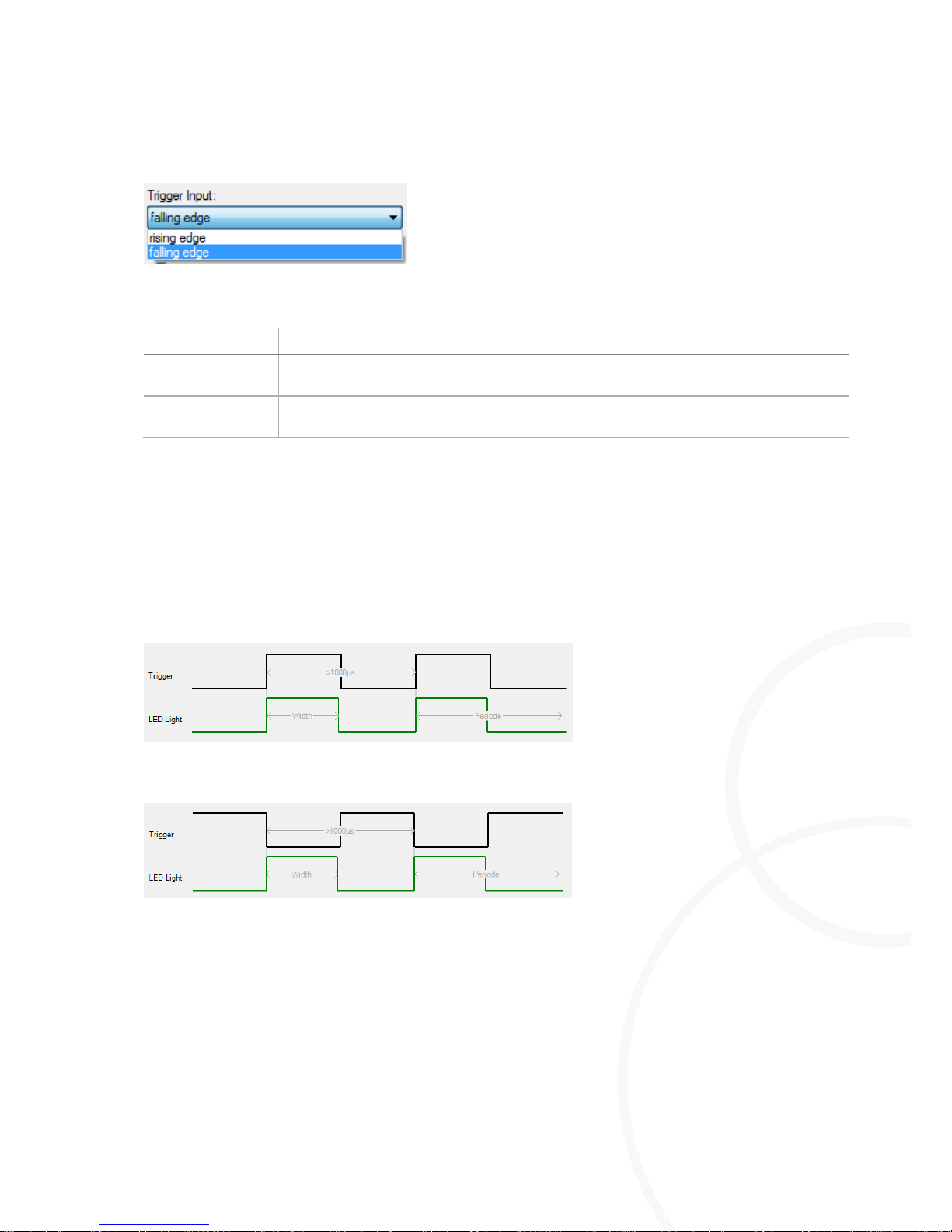
Selecting the trigger input.
Figure 17: Pull-down menu for trigger options
Designation
Description
rising edge
M=Light LED is activated when the level at the input (Flash H / Flash L) is changed
from recessive to dominant.
falling edge
M=Light LED is activated when the level at the input (Flash H / Flash L) is changed
from dominant to recessive.
Highlight the M=Light LED for which the settings are to be made.
Read the required edge from the camera manufacturer's manual.
Select Falling edge or rising edge.
Press Send.
You have adjusted the trigger input in compliance with the camera system connected.
Figure 18: Example, positive edge
Figure 19: Example, negative edge
Page 34
Operating the Software
Software
34
/
58
20.03.2015
8LE-D23_BA_E
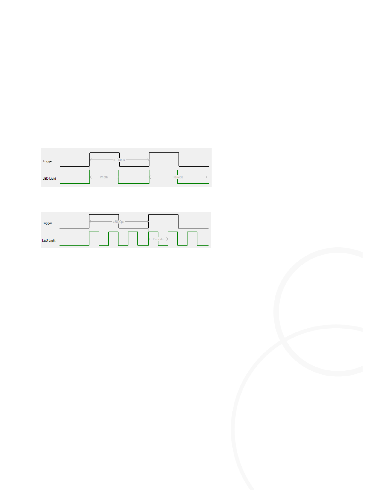
Adjusting the Pulse Count
This parameter is required in case that several pulses of the M=Light LED are necessary, e.g. for
PIV measuring.
Highlight the M=Light LED for which the settings are to be made.
Select the required number of pulses depending on the incoming trigger signal.
Press Send.
You have adjusted the Pulse Count.
Figure 20: Example, 1 pulse per edge
Figure 21: Example, 3 pulses per edge
Page 35
Software
Operating the Software
8LE-D23_BA_E
20.03.2015
35
/
58
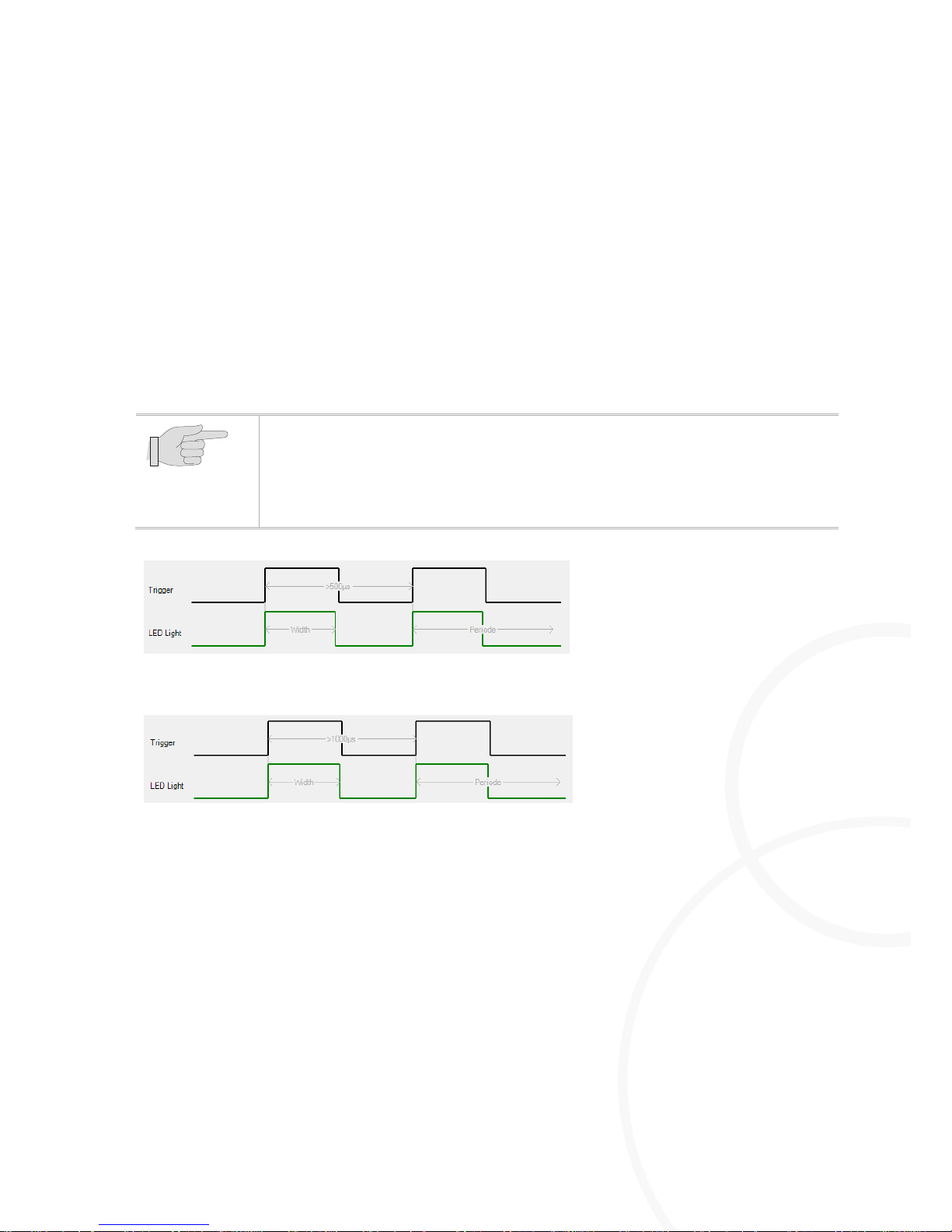
Adjusting the Pulse Period
[µs]
Highlight the M=Light LED for which the settings are to be made.
Read the required period duration from the camera manufacturer's manual.
Set the value by the Pulse Period
[µs]
slide control so that the slide control does NOT become red.
As an alternative, set the frame rate value for the camera by means of the Pulse Period
[fps ]
slide
control so that the control does NOT become red.
The slide control that is currently NOT actuated, follows automatically.
Press Send.
The required period duration has been set for the highlighted M=Light LED.
You can change the operating mode using the Pulse Period [µs] slide control.
At the Pulse Period [µs] slide control set the value 0.
The highlighted LED changes to Auto-Follow operating mode (section
5.3.5.2, page 31).
Figure 22: Example, Pulse period 500µs
Figure 23: Example, Pulse period 1000µs
Page 36
Operating the Software
Software
36
/
58
20.03.2015
8LE-D23_BA_E
Adjusting the Pulse Width
[µs]
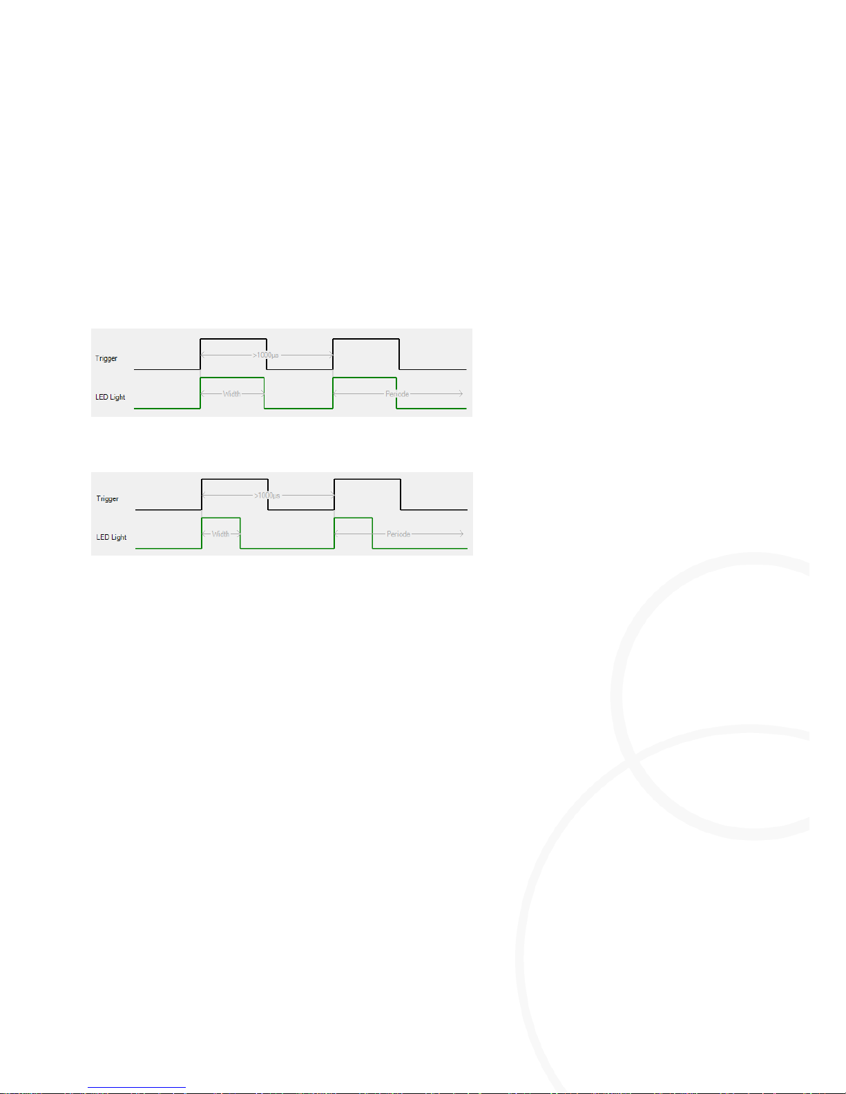
This parameter defines the duration of the light pulse.
Highlight the M=Light LED for which the settings are to be made.
For intensities < 150%, set a value of up to 50% of the Pulse Period
[µs]
value.
For intensities > 150%, set a value of up to 20% of the Pulse Period
[µs]
value.
Press Send.
The required light pulse duration has been set for the highlighted M=Light LED.
Figure 24: Example, Pulse width 500µs at Pulse Period of 1000µs
Figure 25: Example, Pulse width 300µs at Pulse Period of 1000µs
Adjusting the Pulse Delay
With this parameter, the delay of the light impulses is determined according to the edge of the
Sync signal from the camera.
Highlight the M=Light LED for which the settings are to be made.
Read the required delay from the camera manufacturer's manual.
Set the value by the Pulse delay
[µs]
slide control so that the slide control does NOT become red.
Press Send.
The required delay has been set for the highlighted M=Light LED.
Adjusting the Power
This parameter defines the intensity of the light pulse.
Highlight the M=Light LED for which the settings are to be made.
Adjust the intensity at the Power such that NONE of the slide controls become red.
Press Send.
The required intensity has been set for the highlighted M=Light LED.
Page 37

Software
Operating the Software
8LE-D23_BA_E
20.03.2015
37
/
58
Send the set parameters to M=Light LED
Pre-select the parameters as required.
Highlight the M=Light LED to which the settings are to be transmitted.
Press Send.
The set parameters are transmitted to the highlighted M=Light LEDs.
Switching off an Operating M=Light LED.
Highlight the M=Light LED that is to be switched off.
Press OFF.
The highlighted M=Light LED(s) is/are switched off.
Page 38
Operating the Software
Software
38
/
58
20.03.2015
8LE-D23_BA_E
Identification and Correction of Invalid Parameters
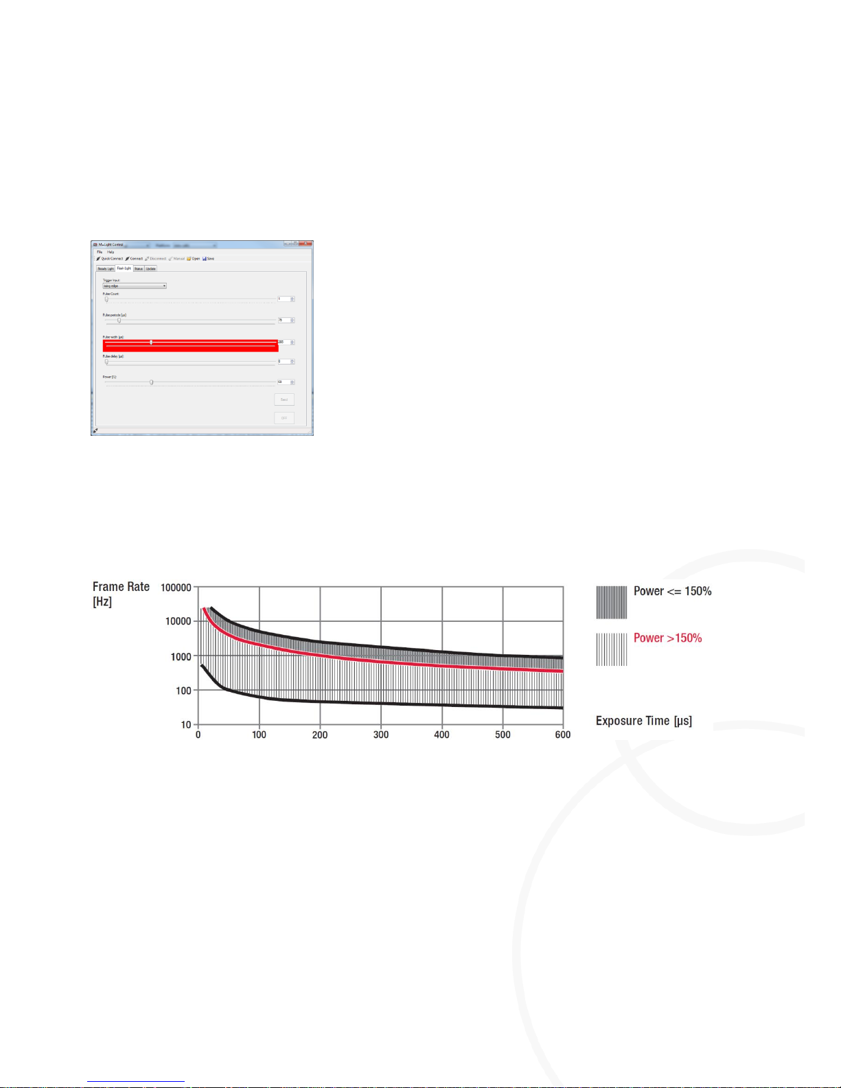
If invalid values have been set for a parameter, the corresponding slide control is marked red in the
display. The graphic illustrations for Trigger and LED Light are NOT displayed. The valid parameters
are provided below (Figure 27, page 38).
Figure 26: Illustration of invalid parameters
Push the slide marked red back until the red marking disappears or adjust other parameters so
that the red marking disappears.
You have successfully parameterized the M=Light.
Figure 27: Admissible parameters
Page 39
Software
Operating the Software
8LE-D23_BA_E
20.03.2015
39
/
58
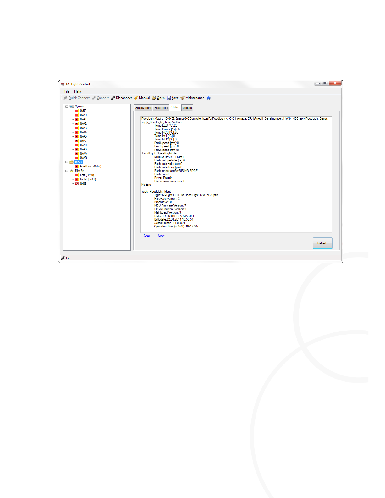
5.3.6. Determining the Status of the Highlighted M=Light LEDs
Figure 28: Status window
Status indication for highlighted M=Light LEDs in the status window.
I Set operating mode, e.g. Steady Light.
I Current condition of the M=Light LEDs, z.B. temperature or fan speed
I Hardware, such as the lighting angle 56°optics
I Firmware, e.g. MCU Firmware Version 7
Determining the Status of the Highlighted M=Light LEDs
Highlight an M=Light LED using the left mouse button.
The status of the marked M=Light LED is shown in the Status window.
Displaying Current Data of all M=Light LEDs Highlighted
Press Refresh.
The data from all M=Light LEDs highlighted is read and displayed in the Status window.
Page 40
Operating the Software
Software
40
/
58
20.03.2015
8LE-D23_BA_E
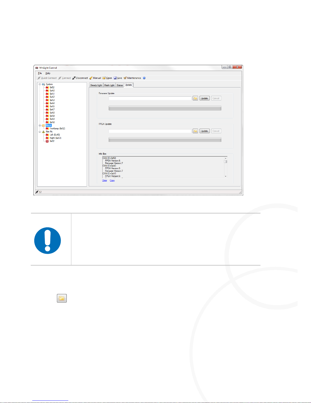
5.3.7. Performing a Firmware or FPGA Update.
Figure 29: Update window
NOTICE!
Failure of the M=Light LED due to incomplete firmware or FPGA update
If the update of an M=Light LED is aborted, this may result in failure of the
M=Light LED.
The firmware or FPGA update must always be completed.
Any M=Light LEDs failed due to an incomplete update must be sent to
MESSRING for repair.
Performing a Firmware Update
Highlight an M=Light LED using the left mouse button.
Press in section Firmware Update.
The browser window for selection of the update file is opened.
Only use update files that have been approved by MESSRING for your M=Light LED.
Press Update.
Wait for the update to be completed, DO NOT abort the process.
The software update has been performed.
Page 41

Software
Operating the Software
8LE-D23_BA_E
20.03.2015
41
/
58
Performing an FPGA update
Highlight an M=Light LED using the left mouse button.
Press in section FPGA Update.
The browser window for selection of the update file is opened.
Only use update files that have been approved by MESSRING for your M=Light LED.
Press Update.
Wait for the update to be completed, DO NOT abort the process.
The firmware update has been performed.
Page 42

Operating the Software
Software
42
/
58
20.03.2015
8LE-D23_BA_E
5.3.7.1. Grouping the M=Light LEDs in M=Light Explorer
After installation of M=Light Control, NO groups are defined yet. In M=Light Explorer all M=Light
LEDs connected to the system are listed one after the other.
If you perform regular parameterization of a certain group of M=Light LEDs, it is meaningful to
group this array in order to be able to perform parameterization simultaneously for the entire group.
It is also possible, to assign one M=Light LED to several different groups at a time.
In the c:\Program Files (x86)\Messring\MLight\ directory, there is a file example_Groups.ini with the
following contents:
Code
Description
[Config]
GroupCount=2
Number of groups that are defined
[Group1]
Serial number of the group
Name=Block
Name of the group [Group 1] as it is indicated in M=Light Control
LightCount=2
Number of M=Light LEDs in group 1
Light1=0x01
Address of the first M=Light LED in group 1
Light1Name=Left
Name of the first M=Light LED in group 1
Light2=0x07
Address of the second M=Light LED in group 1
Light2Name=Right
Name of the second M=Light LED in group 1
SwitchCount=1
Number of switches in group 1
Switch1=0xFF
Address of the first switch in group 1
[Group2]
Serial number of the group
Name=Film pit
Name of the group [Group 2] as it is indicated in M=Light Control
LightCount=2
Light1=0x0A
Address of the first M=Light LED in group 2
Light1Name=Left
Name of the first M=Light LED in group 2
Light2=0x3A
Address of the second M=Light LED in group 2
Page 43

Software
Operating the Software
8LE-D23_BA_E
20.03.2015
43
/
58
Code
Description
Light2Name=Right
Name of the second M=Light LED in group 2
SwitchCount=1
Number of switches in group 2
Switch1=0x2
Address of the first switch in group 2
Grouping the M=Light LEDs in M=Light Explorer
Open the example_Groups.ini file from the directory c:\Program Files (x86)\Messring\MLight and
adjust it in accordance with the grouping settings of the M=Light LEDs in your installation.
In the case that you have NOT installed any switches, enter 0 for the SwitchCount.
If switches are installed, adjust the address of the switches as necessary.
Adjust the M=Light LEDs, groups, and addresses in accordance with your installation.
Save the adjusted file in the same directory using the file name Groups.ini.
Restart M=Light Control.
Re-connect the M=Light LED using Connect.
The groups are now displayed in the M=Light Explorer in the same way as is defined in the
Groups.ini file.
Page 44

Operating the Software
Maintenance
44
/
58
20.03.2015
8LE-D23_BA_E
Chapter 6 Maintenance
Contents
6.1. Maintenance Intervals 45
6.2. Categories 45
6.3. Before Execution of a Test Series 46
6.3.1. M=Light LED 46
6.4. Semi-annual Maintenance 47
6.4.1. Ventilation slots 47
6.4.2. Housing 47
6.5. Maintenance Instructions 48
6.5.1. Acting Safely 48
6.5.2. Cleaning the Housing 49
6.5.3. Cleaning the Ventilation Slots 49
6.5.4. Resetting the service hour meter after having maintenance 49
Page 45
Maintenance
Maintenance Intervals
8LE-D23_BA_E
20.03.2015
45
/
58
6.1. Maintenance Intervals
The following maintenance intervals must be complied with:
I Before Execution of a Test Series
I Semi-annual maintenance (or after 150 operating hours)
6.2. Categories
Category
Description
A
Facility operator with MESSRING operator training
B
Operator's maintenance personnel with MESSRING maintenance training
C
Network administrator
D
MESSRING system specialist
Page 46
Before Execution of a Test Series
Maintenance
8LE-D23_BA_E
20.03.2015
46
/
58
6.3. Before Execution of a Test Series
6.3.1. M=Light LED
Tasks
Comment
Cat
OK?
Defects (description)
Measured values
Visual inspection
Switch on the voltage supply and
check if all M=Light LEDs signal ready
for operation status.
Blue or yellow indication in the LED
array (section 4.1, page 13.
A
OK
Functional check
Briefly switch on the M=Light LED in
set operating mode.
Check if all required M=Light LEDs
operate in the desired operating
mode.
A
OK
Page 47
Semi-annual Maintenance
Maintenance
8LE-D23_BA_E
20.03.2015
47
/
58
6.4. Semi-annual Maintenance
6.4.1. Ventilation slots
Tasks
Comment
Cat
OK?
Defects (description)
Measured values
Visual inspection
Check ventilation slots for coarse
soiling
Remove soiling using a vacuum
cleaner or compressed air with the
voltage supply disconnected. Do NOT
propel fans by means of air pressure.
A
OK
6.4.2. Housing
Tasks
Comment
Cat
OK?
Defects (description)
Measured values
Visual inspection
Check supply line for kinks and scuff
points.
If such points are found immediately
replace the mains cable and optimize
line routing.
A
OK
Check support bracket and fixing
screws for tight fitting and external
damage.
A
OK
Page 48
Maintenance Instructions
Maintenance
48
/
58
20.03.2015
8LE-D23_BA_E
6.5. Maintenance Instructions
6.5.1. Acting Safely
WARNING!
Hazardous body voltage inside the housing
If objects are inserted into the ventilation slots of live M=Light LEDs, this may
cause death or severe injury due to hazardous body voltage.
Disconnect the light from the mains supply before beginning with any
maintenance work.
Do not insert objects into the M=Light LED.
M=Light LED must only be cleaned dry, do NOT use water for cleaning.
Do NOT use M=Light LED in outdoor areas.
NOTICE!
Damage to the fan motors due to overspeed
If a fan motor is propelled e.g. by means of compressed air at speed rates far
beyond its nominal speed, it may be damaged.
Ventilation slots are best cleaned using a vacuum cleaner.
During blow-out of the ventilation slots, do NOT propel the fan with high
air pressure.
Page 49

Maintenance
Maintenance Instructions
8LE-D23_BA_E
20.03.2015
49
/
58
6.5.2. Cleaning the Housing
Disconnect the M=Light LED from the mains line.
Wipe with a dry cloth.
Under NO CIRCUMSTANCES apply grease or cleaning liquid on the LED array.
If required, lightly wipe the LED array with a dry, clean, soft cotton cloth.
You have now optimally cleaned the M=Light LED.
6.5.3. Cleaning the Ventilation Slots
Disconnect the M=Light LED from the mains line.
Hold and stop the fan by pushing up a narrow plastic or wood rod through the ventilation slots
from the bottom.
With the fan blade stopped blow out or vacuum clean the ventilation slots.
Repeat the procedure for all other fans.
You have completed cleaning the ventilation slots. the M=Light LED can now be properly
cooled.
6.5.4. Resetting the service hour meter after having maintenance
Start M=Light control an connect M=Light LED to M=Light control (Section 5.3, page 22).
Activate the Maintenance command.
Push the On / Off switch on the back of the all M=Light LED maintained successfully.
The service hour meter is reset to 0 again.
Page 50

Dimensions and Weights
Technical Data
50
/
58
20.03.2015
8LE-D23_BA_E
Chapter 7 Technical Data
Contents
7.1. Dimensions and Weights 50
7.2. Voltage supply 50
7.3. Performance Data 51
7.1. Dimensions and Weights
Length
255 mm
Width
190 mm
Height
1,480 mm
Weight
5.5 kg
7.2. Voltage supply
Supply voltage
120…265 VAC
Frequency
47…63 Hz
Power consumption
1.000 W
Page 51

Technical Data
Performance Data
8LE-D23_BA_E
20.03.2015
51
/
58
7.3. Performance Data
Color temperature
6,500…7,100°K
(daylight)
Luminous flux
> 100.000 Lumen
Service life of the LEDs
>50.000 h
Angle of radiation, depending on design
23°, 37°, 56°, 71°
Ambient temperature
0…50°C
Hardware-related delay between trigger input and light flash
approx. 10µs
Page 52
Parameterization of M=LIGHT LED via CAN-Bus
Handling
52
/
58
20.03.2015
8LE-D23_BA_E
Chapter 8 Handling
Contents
9.1. Special Accessory - Protective Cover 57
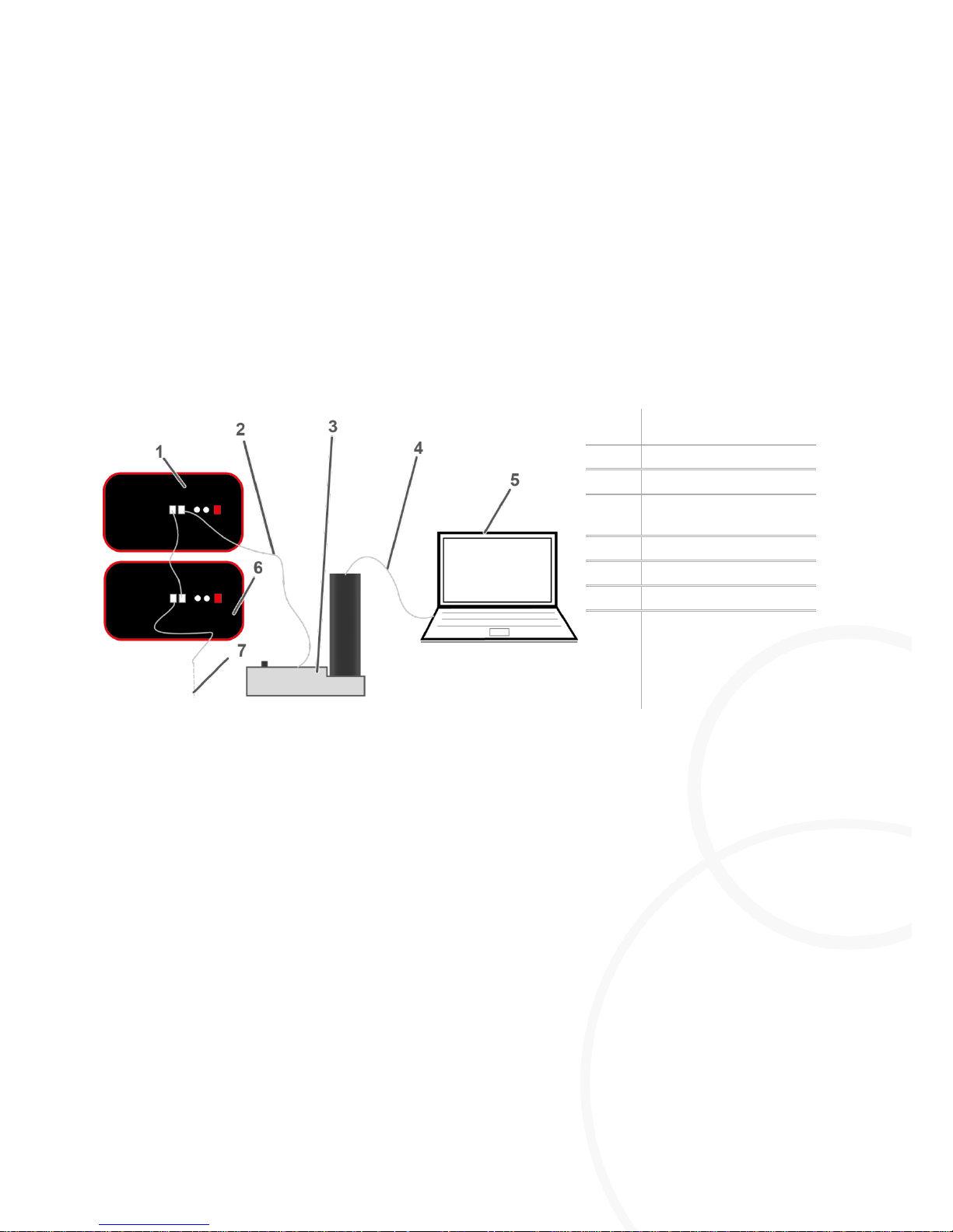
8.1. Parameterization of M=LIGHT LED via CAN-Bus
Item:
Description
1
M=Light LED
2
CAN-bus line
3
Connecting-Set M=Light
LED 8LE-D22-2
4
USB cable
5
PC 6 M=Light LED
7
Additional M=Light
LEDs
Figure 30: M=Light LED, CAN-bus connection
Connect the PC to the CAN-bus interface via USB cable.
Connect the CAN-bus interface with the first M=Light LED.
Connect the first M=light LED with the next M=Light LED via CAN-bus.
Assign a unique CAN-BUS address to all M=Light LEDs in the same CAN-bus line.
You can now parameterize and control the connected M=Light LEDs with the help of the
M=Light control software (section 5.3, page 22).
8.2. Switch-on of M=LIGHT LED via Flash-Bus
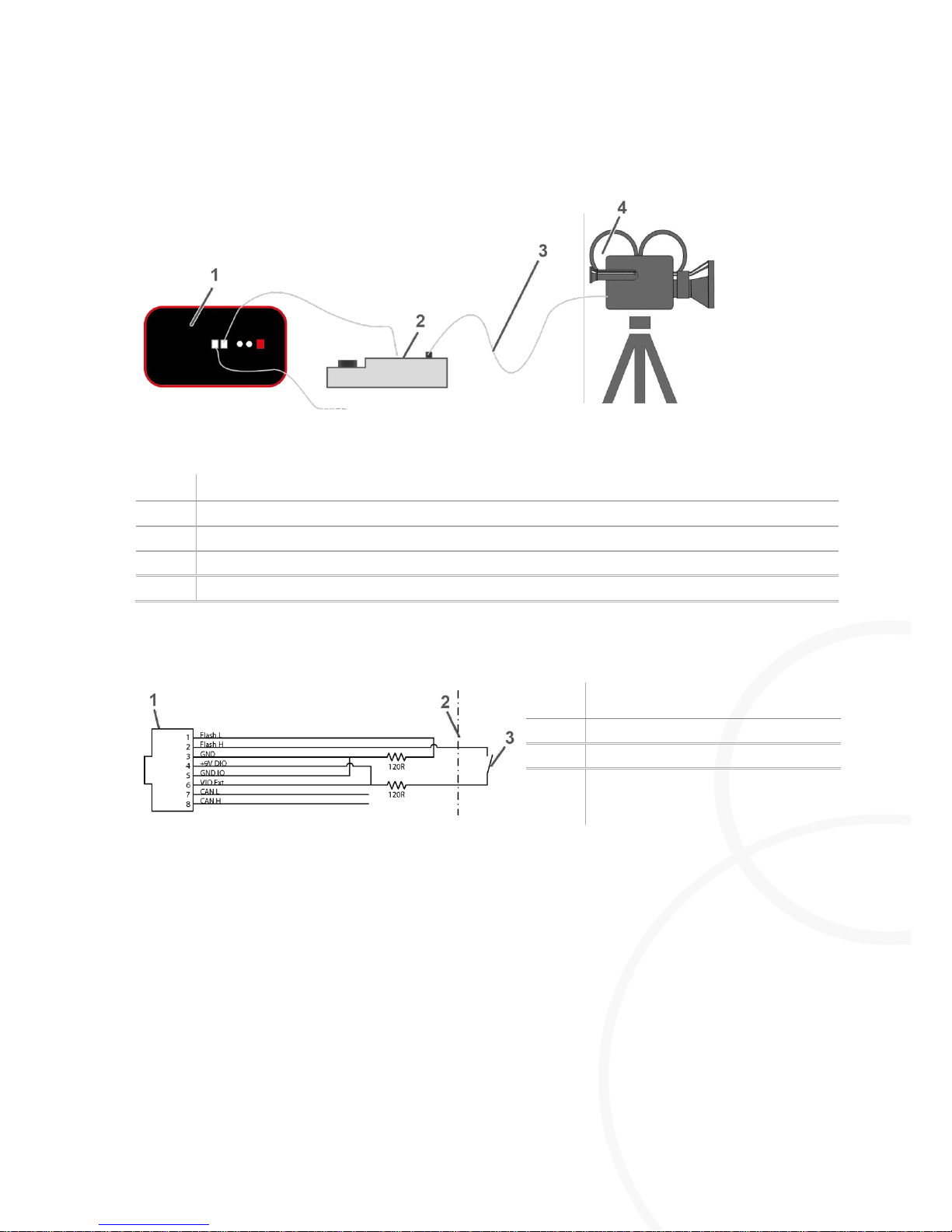
Remote controlled switch-on and switch-off of the M=Light LEDs is always performed by means of
the Flash H and Flash L signals at the Pin 1 and Pin 2 input. Pin 3 & 5 and Pin 4 & 6, respectively,
are bridged for voltage supply of the input assembly. Pin 7 and 8 remain unassigned.
Page 53
Handling
Switch-on of M=LIGHT LED via Flash-Bus
8LE-D23_BA_E
20.03.2015
53
/
58
8.2.1. Synchronizing the M=Light LED with the High-Speed Camera
Figure 31: High-speed camera connection
Item:
Description
1
M=Light LED IN
2
M=Light LED Bus Splitter
3
TTL-sync line from the camera
4
High-speed camera
8.2.2. Triggering M=Light LED with the Help of the Facility Control PLC
Item:
Description
1
M=Light LED IN
2
PLC
3
Potential-free output of the PLC (NO
contact).
Figure 32: PLC connection line
Page 54
Manual Operation of M=LIGHT LED
Handling
54
/
58
20.03.2015
8LE-D23_BA_E
8.3. Manual Operation of M=LIGHT LED
In the case that the M=Light LED has not yet been parameterized via CAN-bus, manual mode is
activated automatically by application of voltage supply.
Manual Mode Adjustment via CAN-Bus
In the user interface of the M=Light-Control software press Manual and switch the LED off.
Once the M=Light LED is supplied with operating voltage again, it remains switched off until the
ON button is pressed on the rear side of the housing or until another operating mode is
selected via the CAN-bus.
8.3.1. Parameterizing M=Light-LED without CAN-Bus Connection
Disconnect M=Light LED from CAN-bus connection
Supply M=Light LED with operating voltage
Press the ON button on the rear side of the housing (Figure 5, Item 7, page 15).
The M=Light LED is now operating in manual mode. You can adjust the intensity with the help
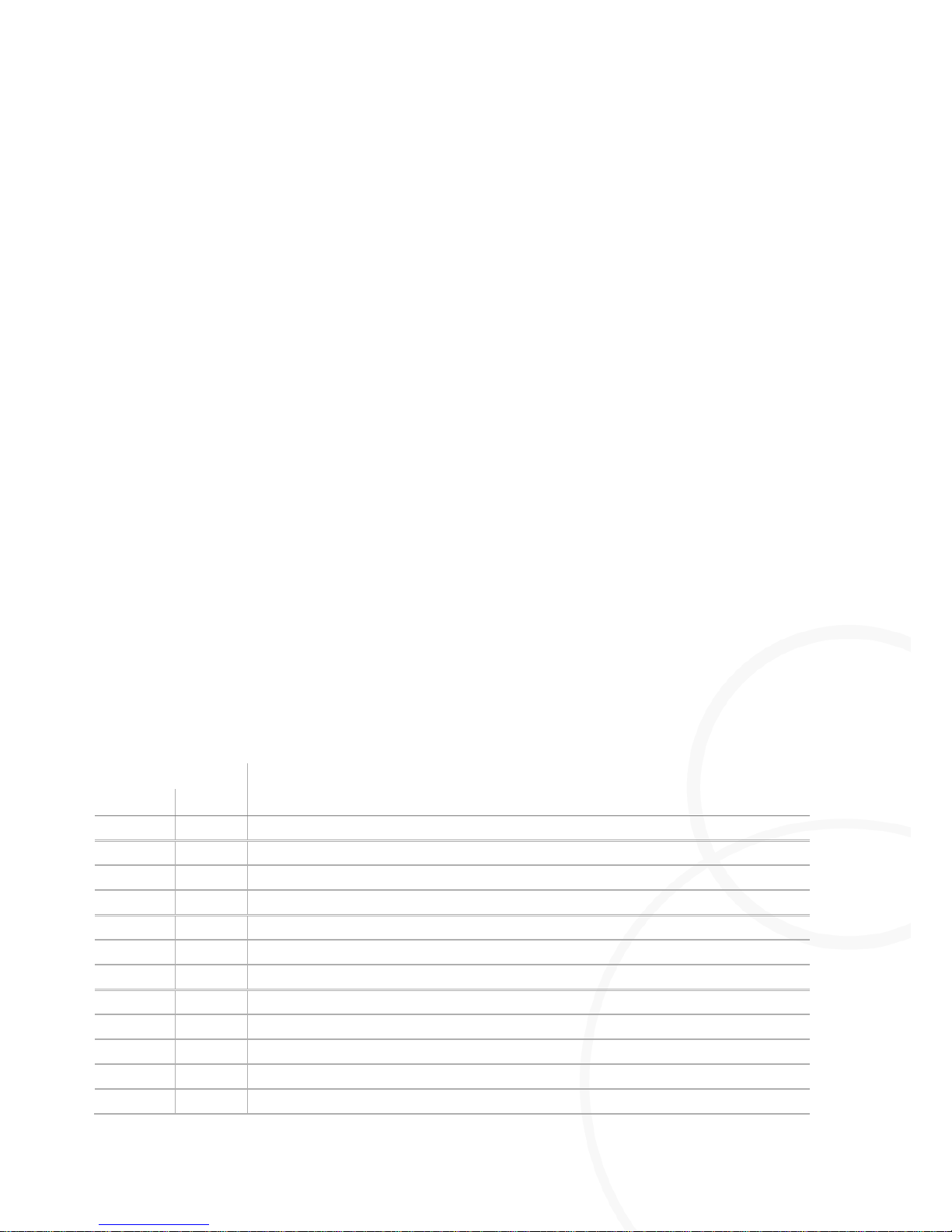
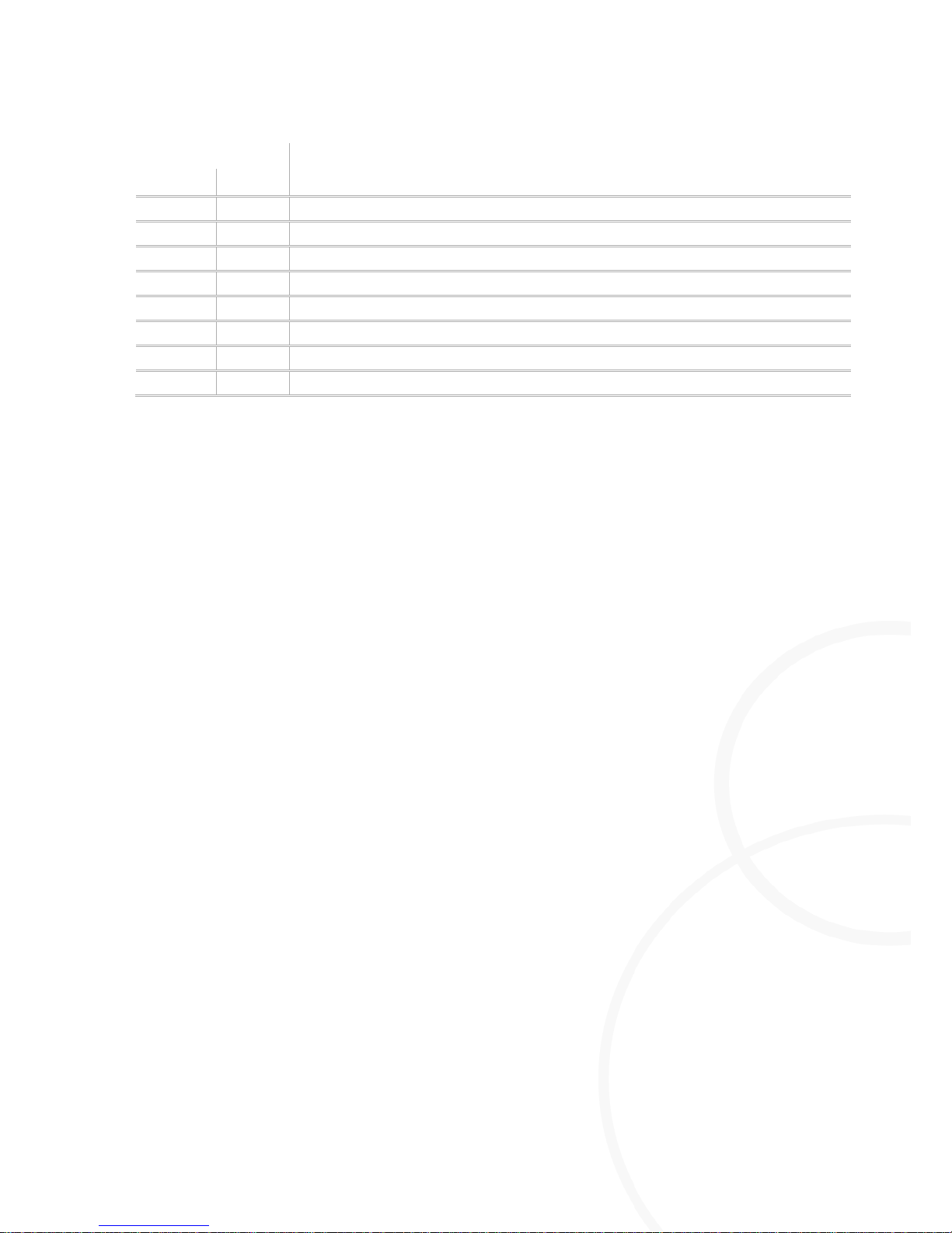
of the CAN-bus address switch on the rear side of the M=Light LED.
In manual mode, the M=Light LED is always parameterized as described below:
I Trigger Input: Falling edge
I Pulse Count: 1
I Pulse Width: 300µs
I Pulse Delay: 0µs
I Intensity depends on the settings at the address switches (table).
CAN address
Description
MSB
LSB
0 1 Steady light, power 1%*
…
….
*Steady light in 1% increments
6 4 Steady light, power 100%*
0 0 Flash, power 100%
6 5 Flash, power 110%
6 6 Flash, power 120%
6 7 Flash, power 130%
6 8 Flash, power 140%
6 9 Flash, power 150%
6 A Flash, power 160%
6 B Flash, power 170%
6 C Flash, power 180%
Page 55
Handling
Manual Operation of M=LIGHT LED
8LE-D23_BA_E
20.03.2015
55
/
58
CAN address
Description
MSB
LSB
6 D Flash, power 190%
6 E Flash, power 200%
6 F Flash, power 210%
7 0 Flash, power 220%
7 1 Flash, power 230%
7 2 Flash, power 240%
7 3 Flash, power 250%
7 4 Flash, power 255%
Page 56

Manual Operation of M=LIGHT LED
Handling
56
/
58
20.03.2015
8LE-D23_BA_E
8.3.2. Switch-on of M=Light LED in Manual Mode
Parameterize the M=Light LED for manual operation with the help of the CAN-bus address
switch.
Supply M-Light LED with operating voltage via the male connector.
Press the red ON/OFF button on the rear side of the housing.
M=Light LED is switched on in manual mode.
8.3.3. Switch-off of M=Light LED in Manual Mode
Press the red ON/OFF button on the rear side of the housing.
M=Light LED is switched off.
Page 57
Special Accessories
Special Accessory - Protective Cover
8LE-D23_BA_E
20.03.2015
57
/
58
Chapter 9 Special Accessories
Contents
9.1. Special Accessory - Protective Cover 57
9.1.1. Purpose of the Protective Cover 57
9.1.2. Structure of the Protective Cover 58
9.1. Special Accessory - Protective Cover
9.1.1. Purpose of the Protective Cover
The protective cover is intended for protection of the LED array from dripping liquids with operation
of the M=Light LED in film pits. Protective Covers are available as special accessories for M-Light
LED.
Product code:
Description
8AD
Protective cover for M=Light LED
Page 58
Special Accessory - Protective Cover
Special Accessories
58
/
58
20.03.2015
8LE-D23_BA_E
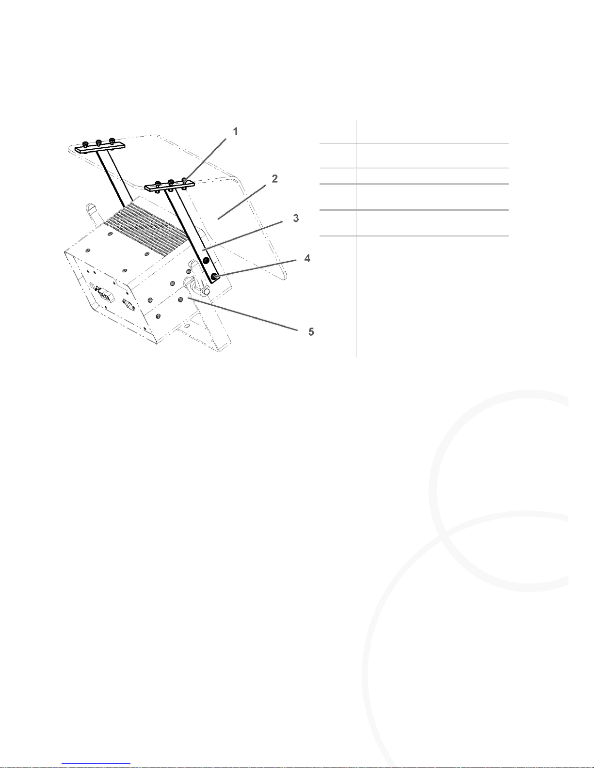
9.1.2. Structure of the Protective Cover
Item:
Description
1
Attachment screws for PMMA
cover
2
PMMA cover
3
Support bracket for protective
cover
4
Attachment screws for support
bracket
5
M=Light-LED housing
Figure 33: M=Light-LED
9.1.3. Retrofitting the Protective Cover to M=Light LED
Disconnect the M=Light LED from voltage supply
Remove the front attachment screws from the housing (2 x 2 screws).
Mount the support bracket by inserting two screws in the positions of the front attachment
screws.
Fasten the PMMA cover to the support brackets with 3 screws per bracket.
Now the protective cover is mounted on the M=Light-LED. You can take the M=Light-LED back
into operation.
 Loading...