


Wide-Dynamic Range
Real Day/Night Camera
Instructions Manual
Before attempting to connect or operate this product, please read these instructions
carefully and save this manual for future use.
CONTENTS
PRECAUTION ..................................................................
IMPORTANT SAFTY INSTRUCTIONS....................................
NOTES OF USE.................................................................
SETUP PROCEDURES
........................................................
•
MAIN CAMERA SETUP MENU1
..................................................
•
MAIN CAMERA SETUP MENU2
..................................................
SPECIFICATIONS..............................................................
290. A.7
ZEIM-0050692G
2
3
4
6
9
15
20
C
M
Y
CM
MY
CY
CMY
K
PRECAUTIONS
The lightening fl ash with arrowh-
ead symbol, within an equilateral
triangle, is intended to alert the
user to the presence of uninsulated "dangerous voltage" within
the product's enclosure that may
be of suffi cient magnitude to
constitute a risk of electric shock
to persons.
The exclamation point within an
equilateral triangle is intende-d
to alert the user to the presence of important operating
and maintenance (servicing)
instructions in the literature
accompanying the appliance
NOTE: This equipment has been
tested and found to comply
with the limits for a Class A
digital device, pursuant to Part
15 of the FCC Rules. These
limits are designed to provide
reasonable protection against
harmful interference when the
equipment is operated in a
commercial environment. This
equipment generates, uses,
and can radiate radio frequency
energy and, if not installed and
used in accordance with the
instruction manual, may cause
harmful interference to radio
communications.
Operation of this equipment in a
residential area is likely to cause
harmful interference in which
case the user will be required to
correct the interference at his
own expense.
FCC Caution: To assure continued compliance, (example – use
only shielded interface cables
when connecting to computer
or peripheral devices). Any
changes or modifi cations not
expressly approved by the party
responsible for compliance could
void the user’s authority to oper-
ate this equipment.
The serial number of this product
may be found on the top of the
unit. You should note the serial
number of this unit in the space
provided and retain this book as a
permanent record of your purchase
to aid identifi cation in the event of
theft.
Model No.
Serial No.

1) Read these instructions
All the safety and operating instruct ions should be read before the prod-
uct is operated.
2) Keep these instructions
The safety instructions and instruct ion manual should be retained for
future reference.
3) Heed all warnings
All warnings on the product and in
the instruction manual should be
adhered to.
4) Follow all instructions
All operating and use instructions
should be followed.
5) Cleaning
Disconnect this video product from
the power supply before cleaning.
6) Attachments
Do not use attachments not recomm ended by the video product manufac-
turer as they may cause hazards.
7) Water and Moisture
Do not use this video product near
water, for example, near a bath tub,
wash bowl, kitchen sink, or laundary
tub, in a wet basement, or near a
swimming pool and the like.
8) Accessories
Use only with stand, tripod, bracket,
or table recommended by the manuf acturer, or sold with the video prod uct. Any mounting of the product
should follow the manufacturer's
instructions, and should use a moun ting accessory recommended by the
manufacturer.he video product may
fall, causing serious injury to a child
or adult, and serious damage to the
product.
9) Ventilation
This video product should never be
placed near or over a radiator or heat
register. This video product should
not be placed in a built-in installation
IMPORTANT SAFETY INSTRUCTIONS
Power-Supply cords should be routed
so that they are not likely to be walk ed on or pinched by items placed
upon or against them. paying particu lar attention to cords at plugs, scre ws and the point where they exit
from such as a bookcase or rack
unless proper ventilation is provided
or the manufacturer's instructions
have been adhered to.
10) Servicing
Do not attempt to service this video
product yourself as opening or remo ving covers may expose you to dang erous voltage or other hazards. Refer
all servicing to qualifi ed service pers-
onnel.
11) Power Source
This video product should be opera ted only from the type of power sou rce in dicated on the marking label.
If you are not sure the type of power
supply to your location, consult your
product dealer.
12) Damage Requiring service
Disconnect this video product from
the power supply and refer servicing
to qualifi ed service personnel under
the following conditions.
a. When the power-supply cord or plug
is damaged.
b. If liquid has been spilled, or objects
have fallen into the video product.
c. If the video product has been expos ed to rain or water directly.
d. If the video product does not oper ate normally by following the oper ating instructions in this manual.
Adjust only those controls that are
covered by the instruction manual as
an improper adjustment of other
controls may result in damage and
will often require extensive work by a
qualifi ed technician to restore the
video prodcut to its normal operation.
13) Safety Check
Upon completion of any service or
repairs to this video product, ask the
service technician to perform safety
checks to determine that the video
product is in proper operating condi-
tion.
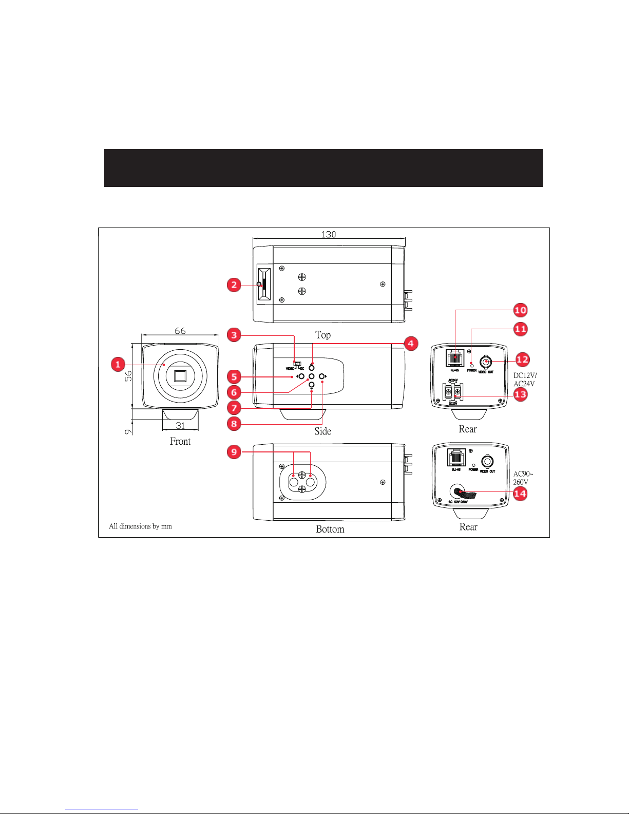
NOTES OF USE
(1) Lens mount
This camera uses CS mount to connect the lens, if you are using a C mount
lens, you can fi nd the C-to-CS mount in
the accessory.
(2) Easy backfocus adjust
You can use this adjust to micro adjust the focus.
(3) Auto Iris switch(Video/DC)
Use this switch to select which type of
auto iris control you want to use.
(4) Up button
Use this button to move the cursor
upward or to select different settings in
the OSD menu.
(5) Left button
Use this button to move the cursor to
the left or to exit the selected item in the
OSD menu.
(6) Enter button
Use this button to enter the selected
item or to confi rm the settings in the OSD
menu.
(7) Down button
Use this button to move the cursor
downward or to select different settings
in the OSD menu.
(8) Right button
Use this button to move the cursor to
the right or to enter the selected item in
the OSD menu.
•PARTs’ NAMES AND LOCATIONS
(9) Tripod mounting holes
Use this holes to connect to a
bracket or to a housing according to your
applications.
(10) RJ45 port
External devices can use RS485 protocol to control this camera via this port.
(11) Power indicator
(12) BNC connector
Connect this cable to the video-in
connector of respective apparatus.
(13) DC12V/AC24V power connector
Connect this connector to the respective power.(DC12V/AC24V model only)
WARNING: This apparatus must be EARTHED.
(14) AC90V~260V
Connect this connector to the respective power.(AC90~260V model only)
WARNING: This apparatus must be EARTHED.
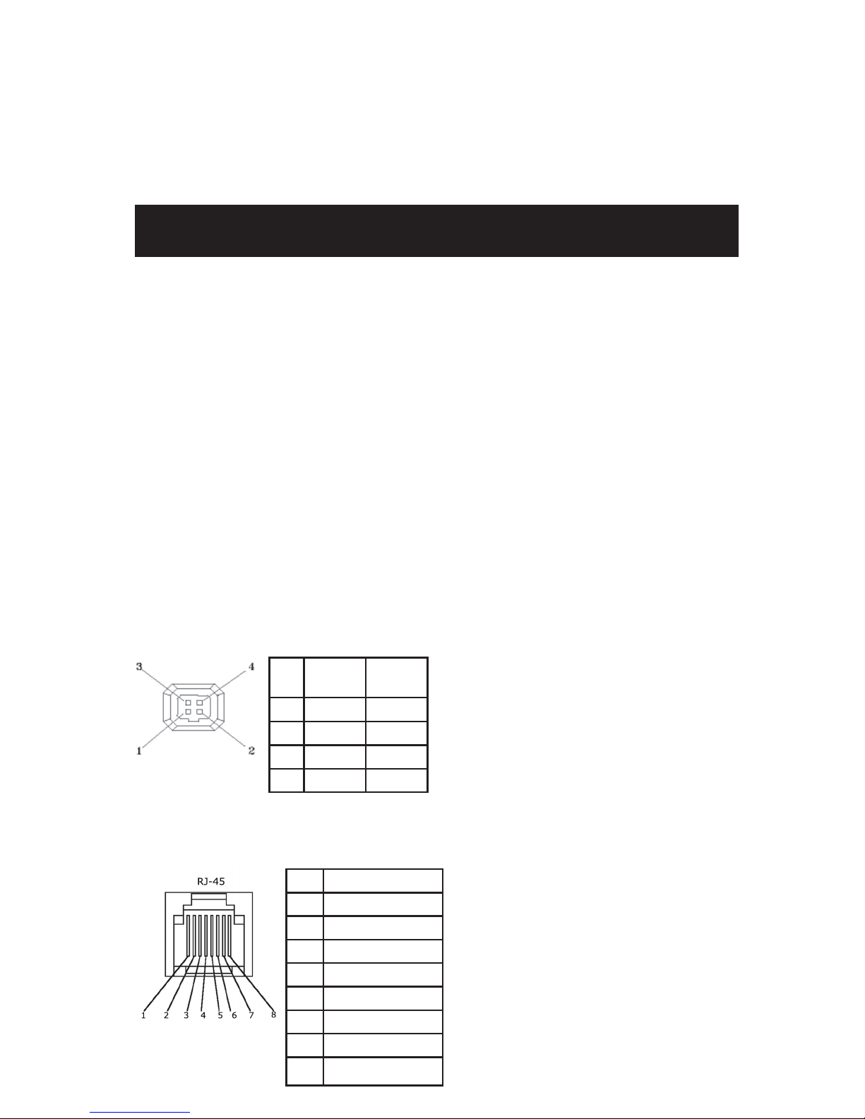
(1)
Iris connector
(2)
RJ45 connector
NO Video
Lens
DC
Lens
1 +12V Damp-
2 NC Damp+
3 Video Drive+
4 GND Drive-
NO Function
1 Data+ (RS-485)
2 Data- (RS-485)
3NC
4C
5G
6B
7 GND
8NC
NOTES OF USE
•CONNECTIONS

SETUP PROCEDURES
D/N MODE AUTO
D/N LEVEL HIGH
D/N DELAY 15SEC
ALC / ELC <ALC >
SHUTTE R O F F
SENS UP OFF
GA I N TUR BO
SYNC ---
BLC OFF
WH I T E B A L A TW 2
NEXT EX I T CANCE L DE FAULT
ID MENU
IP POS OFF
ID
ABCD E F GH I J K LM
NOPQRS TUVWXYZ
0123456789:<>
‘‘-. ,;*/
EX I T CLEAR
MAIN MENU 1
CAMERA ID Setup
GAMMA 0 . 4 5
APERTURE MI D
PTZ <SET>
MI RROR OF F
PR I VACY ZONE <OF F >
ID <SETTING>
BLEMI SH <DET>
FLICKERLESS O FF
BACK EX I T CANCE L DE F AULT
PR I VACY ZONE MENU
PR I VACY ZONE OFF
BLOCK 1 SET CLR
EX I T CLEAR ALL
MAIN MENU 2
PRIVACY ZONE SETUP
ALC/ELC SETUP
ADDR E S S 0 0 1
PROTOCOL PE LCO P
BAUD RATE 4 8 0 0
SOFT VER A.X.X
EX I T DEF AULT
PROTOCOL MENU
A L C / E L C MENU
A L C / E L C A L C
W D O F F
W D L E V E L DISABLE
W D C O N T R A S T DISABLE
L E N S D C
LE V E L - - - - -* - - - -
E X I T
•OSD SETUP MENU (Default settings)
WITH IR LAMP NO
 Loading...