

Page 1

www.messoa.com
Quick Start Guide
2MP High Speed PTZ Dome Network Camera
NIC990
ZEIM-4000759G A2
Page 2

Page 3
NIC990 l Quick Start Guide 1
Cautions
The camera must be installed on a solid mounting surface.
Please make sure the power source is AC 24V / PoE+. Although the camera can be
powered via a PoE+ connection, the PoE+ power source won’t be able to drive the
camera with its equipped heater being operating simultaneously. Users are supposed
only to supply the camera with AC 24V continuously for the heater inside the camera
to operate.
Keep the camera and other accessories dry.
Before cleaning the unit, please rst unplug the power
The power cable must be properly secured as improper connections may cause a
short circuit, re hazards, or serious damage and hazards.
During prolonged inactivity, please unplug the power cable and the video cable to
avoid damage from lightning strike and power surges
The use of CSA certied/ UL Listed Class 2 power adapters is required to ensure
compliance.
Warnings
Installation and maintenance should be performed only by qualied and experienced
technicians to conform to all local codes and to maintain your warranty.
Please follow the Caution labels on the product and Instruction Manual to ensure
operation safety.
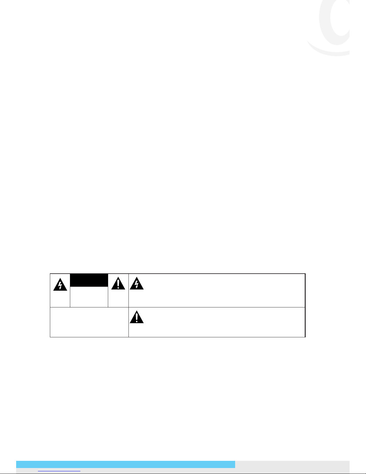
CAUTION
THIS SYMBOL INDICATES THAT DANGEROUS
VOLTAGE CONSTITUTING A RISK OF ELECTRIC
SHOCK IS PRESENT WITHIN THE UNIT.
RISK OF
ELECTRIC SHOCK
DO NOT OPEN
CAUTION: TO REDUCE THE RISK OF
ELECTRIC SHOCK, DO NOT REMOVE
THE COVER. NO USER-SERVICEABLE
PARTS INSIDE. REFER SERVICING TO
QUALIFIED SERVICE PERSONNEL.
THIS SYMBOL INDICATES THAT IMPORTANT
OPERATING AND MAINTENANCE INSTRUCTIONS
ACCOMPANY THIS UNIT.
Copyright
No part of this document may be reproduced or transmitted in any form or by any
means, electronic or mechanical, for any purpose, without the express written permission
of MESSOA.
© 2012 All rights reserved.
Disclaimer
Page 4
2 NIC990 l Quick Start Guide
Specications and information contained in this document are presented as accurately
as possible as of the time of release, but are not guaranteed to be entirely free of
error. MESSOA assumes no responsibility for errors or omissions that may appear in
this document and reserves the right to change this publication at any time without
obligation to notify anyone of such revisions or changes.
FCC Class A Notice
This device complies with Part 15 of the FCC Rules. Operation is subject to the following
two conditions:
(1) this device may not cause harmful interference, and (2) this device must accept any
interference received, including interference that may cause undesired operation.
Any changes or modications to the equipment not expressly approved by MESSOA
could void the user’s authority to operate the equipment.
CE Compliance
This equipment complies with the following requirements of the EMC Directive
2004/108/EC for CE Marking: EN 55022: 2010 Class A, EN 61000 and EN 50130.
WEEE
Waste Electrical and Electronic Equipment
Correct disposal of this product (applicable in the European Union and other
European countries with separate collection systems). This product should
be disposed of, at the end of its useful life, as per applicable local lows,
regulations and procedures.
Page 5
NIC990 l Quick Start Guide 3
1. Introduction
This quick start guide is intended to provide installers with basic instructions for installing
and conguring the Network Speed Dome Camera. For more detailed information of
using and conguring the product, please refer to the User’s Manual available on the
provided CD-ROM.
Package Contents
Check the items supplied with your network speed dome camera against the following
list. If anything is missing, please contact your dealer.
Quick Start Guide x1
CD-ROM (IP Finder Utility & User Manual) x1
Power Adapter x1
RJ-45 Coupler x1
Screw (1/4-20UNC,12mm) x1
Torx Key (33x90L) x1
Allen Wrench (4mm) x1
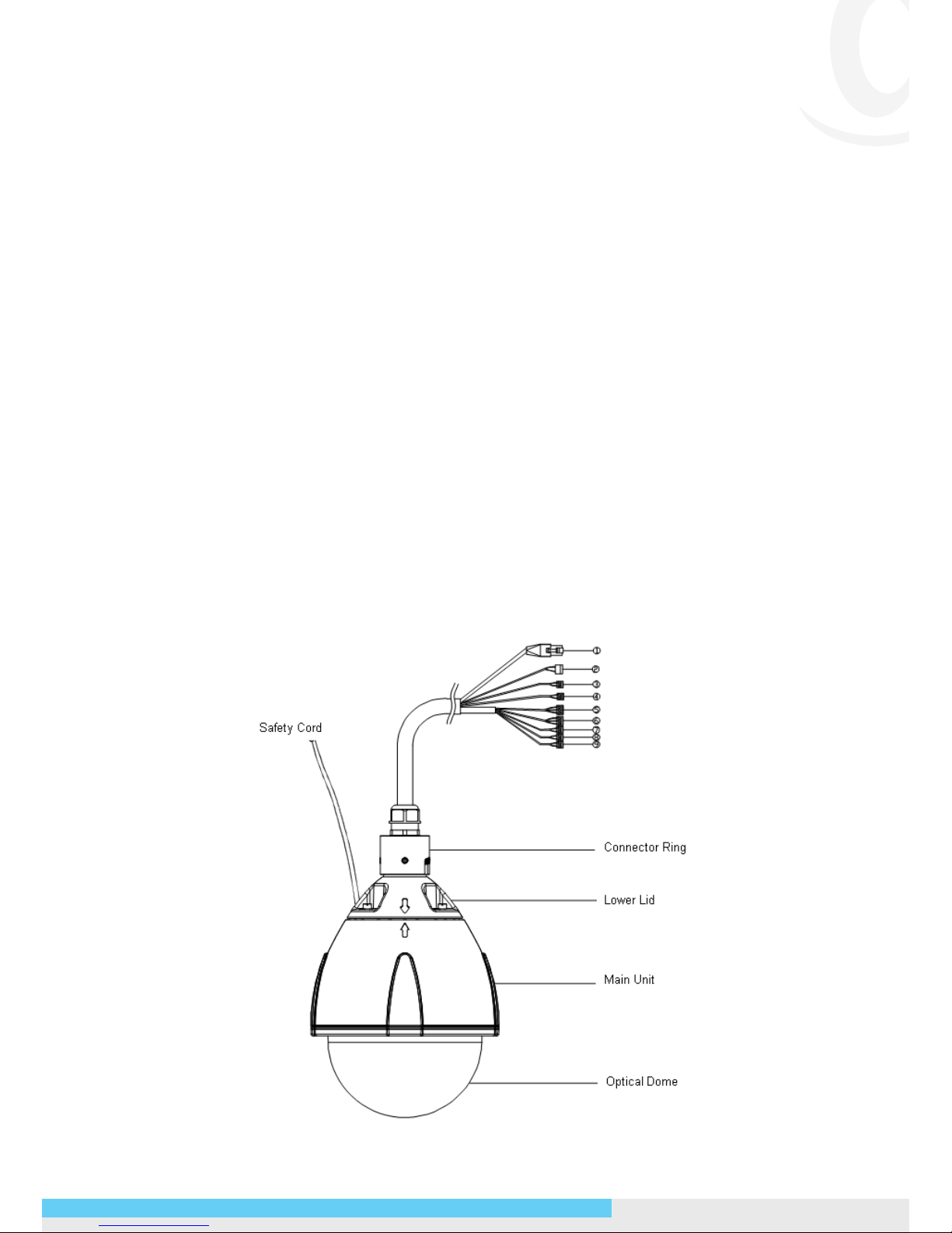
Part Names
Page 6

4 NIC990 l Quick Start Guide
The table below describes the connectors of the camera.
No. Connector Descriptions
1 RJ-45 For Ethernet/PoE+ connection. Attach this
co nec tor to t he LAN p or t o f a st an dar d
10BaseT/100BaseTX device, e.g. hub, switch or
router. With connecting to a PoE+ compliant PSE,
the camera can be powered via this RJ-45 cable.
2 Power (Black/White) Wire this terminal block to an AC power supply.
If you are to use power via the Fast Ethernet
connection, this terminal block is not used.
3 Reset (Orange/White) Wire the terminal block with an on/off switch or
just have the two conducts shorted to restart the
system.
4 Audio In (Black/White) Connect to an external microphone to record
audio around the camera site.
5 Alarm Out Open (Light
Green)
Alarm Out Com (Black)
Alarm Out Close (Purple)
Wired to send signals to external devices for
alarm purposes.
6 Alarm In 5 (Blue)
Alarm In 6 (Green)
Alarm In GND (White)
Wired to receive alarm signals triggered by
external devices.
7 Alarm In 1 (Red)
Alarm in 2 (Brown)
Wired to receive alarm signals triggered by
external devices.
8 Alarm In 3 (Yellow)
Alarm in 4 (Orange)
Wired to receive alarm signals triggered by
external devices.
9 Default (Pink/Gray) Wire the terminal block with an on/off switch or
just have the two conducts shorted for at least
ve seconds to load factory default.
Note
If the alarm terminals are connected with external devices, the Alarm In GND (White)
contact must be wired to ground.
Page 7

NIC990 l Quick Start Guide 5
2. Installation and Initial Conguration
Note: Installation should be performed only by qualied and experienced technicians to
conform to all local codes and to maintain your warranty.
Wiring Cables
1. Connect the camera to a power source, using one of these options:
• AC 24V: Connect the power terminals to AC 24V power source.
• PoE+: Connect the equipment via a category 5/5e or higer UTP/STP cable to a
PoE+ (802.3at) compliant Ethernet switch or router.
Note
Although the camera can be powered via a PoE+ connection, the PoE+ power
source won’t be able to drive the camera with its equipped heater being operating
simultaneously. Users are supposed to only supply the camera with AC 24V continuously
for the heater inside the camera to operate.
2. For pure Ethernet connection, connect the camera via a category 5/5e or higer UTP/
STP cable to a network device such as hub, switch or router.
3. Optionally connect to external alarm triggering/responding devices via alarm-in/
alarm-out cables.
4. Optionally connect an external microphone to record surrounding audio.
5. Optionally wire the Reset connector for system reboot.
6. Optionally wire the Default connector for loading factory default.
Initial Conguration
Before connecting the camera to your network infrastructure, it’s suggested that you
connect the camera to a computer rst to perform initial congurations.
1. To access the camera, the PC must be on the same network segment as the camera.
The default IP address of the camera is a static one (192.168.1.30). Congure your
PC’s IP address as 192.168.1.X (where X is a number between 2 to 254 excluding 30)
and subnet mask as 255.255.255.0, and then your PC should be able to access the
camera.
• IP Address: 192.168.1.100
• Subnet Mask: 255.255.255.0
2. Using an Ethernet cable, connect the camera to the computer.
The LAN port of the camera supports auto MDI/MDIX so there is no need to use a
cross-over cable.
Page 8

6 NIC990 l Quick Start Guide
3. On the PC, launch a web browser and enter the IP address of the camera in the URL
eld:
http://192.168.1.30
4. When prompted for login, enter the default user name: admin and password: 1234
to log in. Note that the user name and password are case-sensitive.
5. Congure the settings to meet your requirements. For more information, refer to the
User Manual on the provided CD-ROM.
Network Deployment
There are many different ways that you can connect the camera to your network,
depending on your applications requirements. You should always set the camera’s
network settings according to your network congurations. The following diagrams
depict some typical applications with guidelines on network settings. For more
information on network settings, always consult with your network administrator or ISP
as required.
Type 1: Direct Connection to a PC
Directly connect the RJ-45 cable of the camera to a PC.
To extend the connection length, you should use an RJ-45 female/female coupler to
connect two category 5/5e UTP/STP cables together.
RJ-45 Coupler
Note
Although an RJ-45 coupler is used to extend the connection length, the total length
between the PC and the IP camera must not exceed 100 meters (328 feet). The LAN port
of the camera supports auto MDI/MDIX (Medium dependent interface crossover) so
there is no need to use cross-over cable.
To access the camera, the PC must be on the same network segment as the camera. The
default IP address of the camera is a static one (192.168.1.30). Congure your PC’s IP
address as 192.168.1.X (where X is a number between 2 to 254 excluding 30) and subnet
Page 9
NIC990 l Quick Start Guide 7
mask as 255.255.255.0, and then your PC should be able to access the camera.
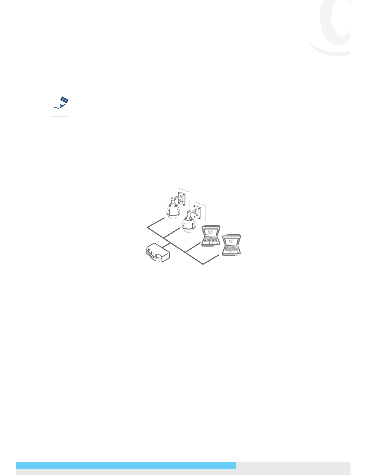
Type 2: Connection to LAN
To add the camera(s) to an existing LAN, just connect the camera(s) to the router, switch
or hub on your network. If you want to provide the camera power via the Ethernet
connection, a PoE+ compliant hub/switch is required.
Note
The LAN port of the camera supports auto MDI/MDIX (Medium dependent interface
crossover) so there is no need for an uplink port or the use of a cross-over cable.
Assign an IP address to your camera following your network IP allocation policy. The
IP address can be manually specied by users or by a DHCP server, if available on your
network.
Then, you can monitor and mange the camera via a web browser from a local PC.
Router/Switch/Hub
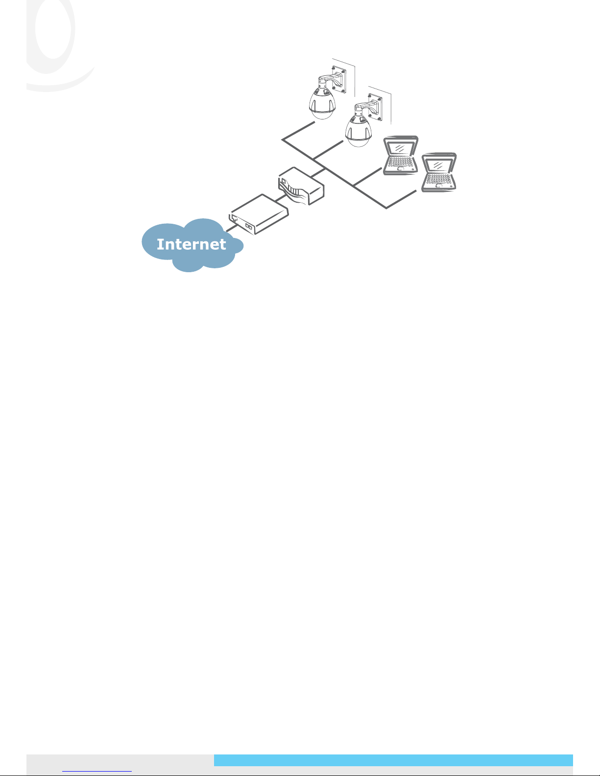
Type 3: Remote Connection via the Internet
If the network where the camera resides is connected to the Internet, you can also
provide remote access to your camera over the Internet.
Typically a broadband router has a built-in DHCP function to assign a local IP address to
your camera. You can alternatively assign a xed IP address to the camera to prevent it
from frequently changing.
Page 10
8 NIC990 l Quick Start Guide
xDSL/Cable Modem
Router
To access the camera from a local PC, simply use the local IP address of the camera.
To enable remote access, you must congure your router/rewall to forward an incoming
request to that xed local IP address of the camera. Therefore, when an external host
sends a request to access your camera, the request will rst reach the router’s external IP
address and then be forwarded to the local IP address of the camera.
Page 11

NIC990 l Quick Start Guide 9
General Warranty Policy and Limitations
MESSOA Technologies Inc. (MESSOA) offers a limited 3 (three) year warranty on any
product defect (zoom Lens, IR LED light bulbs, and IP speed dome’s IP Board warranty
are limited to 1 (one) year) from the date of purchase from MESSOA. The actual term of
warranty will be determined by the product serial number.
The product warranty does not apply to damages caused by acts of nature, abuse,
misuse, misapplication, improper interfacing, improper repair, unauthorized modication,
or any operation beyond the design limits. Consumable parts are not covered by the
warranty for whatever is categorized as spare parts, including plastic housing and covers,
accessories, and packaging materials.
Should the product malfunction, please contact the party from whom you purchased the
product for assistance.
Page 12

MESSOA TAIWAN, R.O.C.
6F, No.26, Wuquan 6th Rd., Wugu District,
New Taipei City 248, Taiwan (R.O.C.)
Tel: +886-2-2298-3908
Fax: +886-2-2298-3909
E-mail: [email protected]
MESSOA USA
13611 12th St, Unit B Chino, CA 91710, USA
Tel: +1-909-590-5955
Fax: +1-909-590-2374
E-mail: [email protected]
MESSOA SHANGHAI INC.
Room 301, Yuanzhong Ofce Building, No.2007
Hongmei Rd., Xuhui District, Shanghai 201103
Tel: +86-21-6495-9236
Fax: +86-21-6495-9238
E-mail: [email protected]
MESSOA JAPAN
8F Salute Bldg 72 Yoshidamachi,
Naka-Ku Yokohama Kanagawa 231-0041, Japan
Tel: +81-45-2500680
Fax: +81-45-2500681
E-mail: [email protected]
All brand names and registered trademarks referred in this document are the property of their respective owner(s).
All designs and specications are subject to change without prior notice.
 Loading...