

Page 1

Mounting Installation Guide
NDF820(PRO)/821(PRO) Dome Camera
Rev A2
Page 2

Mounting Installation Guide
Table of Contents
1. Introduction.............................................................................................3
Before Installation ....................................................................................3
2. Ceiling Surface Mount............................................................................3
3. L-Type Wall Mount..................................................................................4
Dimensions – SAB749-1W ......................................................................6
4. Cable Management Wall Mount.............................................................7
Dimensions – SAB755.............................................................................9
5. Pendant Mount......................................................................................10
Dimensions – SAB755M........................................................................11
2
Page 3

Mounting Installation Guide
1. Introduction
This mounting installation guide is intended to provide installers with basic
instructions of how to mount the NDF820(PRO)/NDF821(PRO)* dome camera
(hereafter referred to as the camera) using optional accessories from MESSOA. If
you are using other specialized mounting accessories or tools, always refer to the
instruction document supplied with that product.
Note: Always use the screws as instructed by this guide to ensure proper
installation.
*The appearance of the NDF820(PRO) and NDF821(PRO) are very similar. The NDF820(PRO)
will be used as the example in the illustration.
This guide will describe the following mounting methods:
Ceiling Surface Mount
L-Type Wall Mount
Cable Management Wall Mount
Pendant Mount
Before Installation
Before mounting the camera onto the bracket, please first secure the mount bracket
of your choice firmly at the desired position to a solid surface using appropriate
screws and plugs. Also make sure to route all the required cables properly.
2. Ceiling Surface Mount
This mounting method requires no additional accessory. Refer to the user manual of
the camera for mounting instructions.
3
Page 4
Mounting Installation Guide
3. L-Type Wall Mount
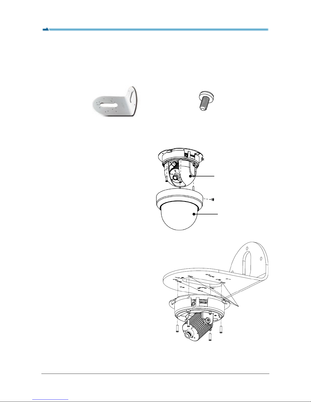
Before beginning the following procedure, please make sure to have these items
ready:
L-Type Wall Mount Bracket
(SAB749-1W)
M4x20mm flathead
machine screw x4
(supplied with the camera)
1. Loosen the screw(s) that securing
the dome cover to remove the dome
cover. Then remove the inner liner.
2. Attach the SAB749-1W bracket to
desired location using appropriate
screws (user-supplied).
3. Attach the camera to the bracket.
Orient the base casing to align with
the three #2 holes on the bracket
and then fasten with the four M4x20
flathead machine screws (supplied
with the camera).
Dome Cover
Inner Liner
#2 holes
M4x20 flathead
machine screws
4
Page 5
Mounting Installation Guide
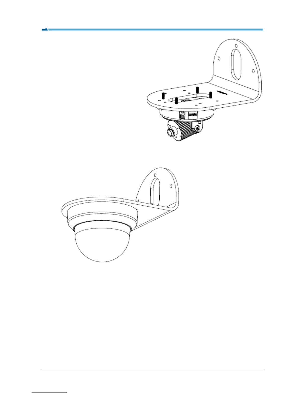
Note that by using the supplied
M4x20 screws in Step 3, the
screws will protrude from the
bracket surface by about
12.5mm.
4. Adjust the lens to the desired angle.
5. Re-attach the inner liner and the dome cover.
5
Page 6
Mounting Installation Guide
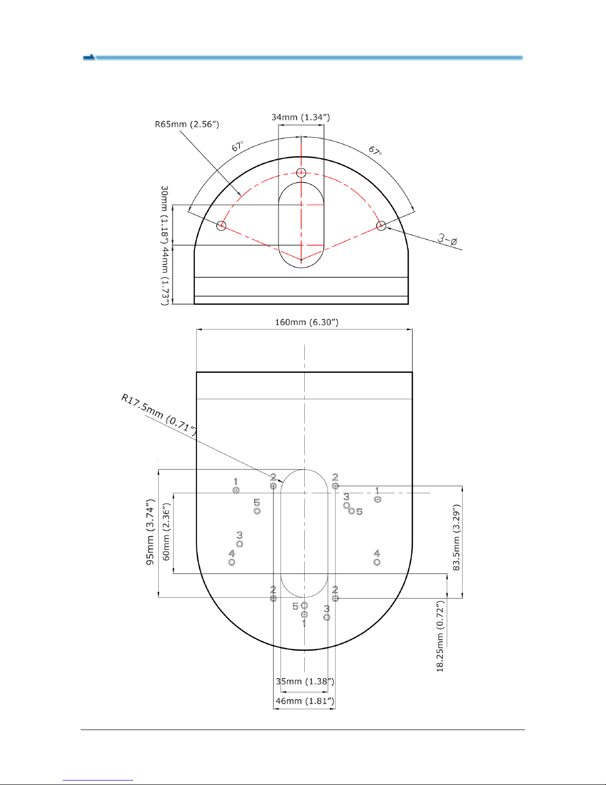
Dimensions – SAB749-1W
6
Page 7
Mounting Installation Guide
4. Cable Management Wall Mount
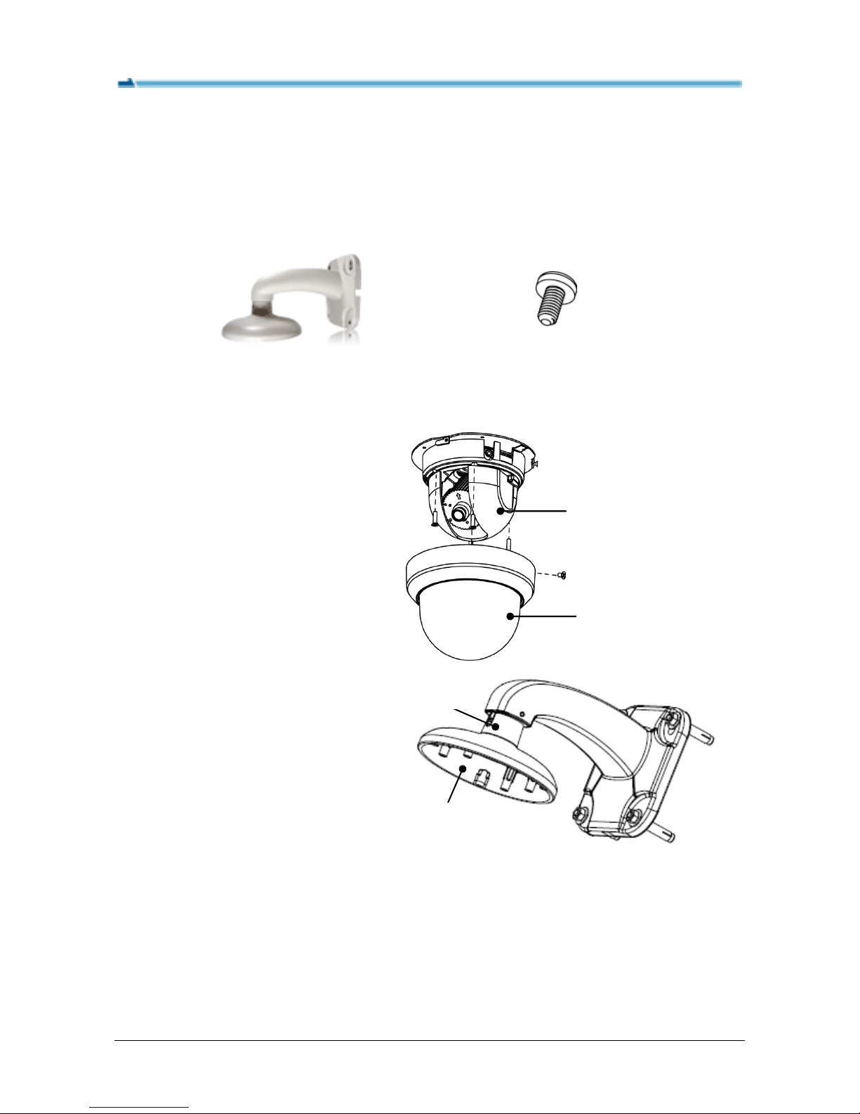
Before beginning the following procedure, please make sure to have these items
ready:
Cable Management Wall Mount
Bracket (SAB755)
M4x20 flathead machine screw x4
(supplied with the camera)
1. Loosen the screw(s) that secure
the dome cover to remove the
dome cover. Then remove the
inner liner.
2. Refer to the instruction
document of the bracket, and
assemble the conduit adapter
and the dome cap to the
bracket. Then route the cables
of the camera through the
bracket.
Dome Cover
Inner Liner
Conduit
adapter
Dome Cap
7
Page 8
Mounting Installation Guide
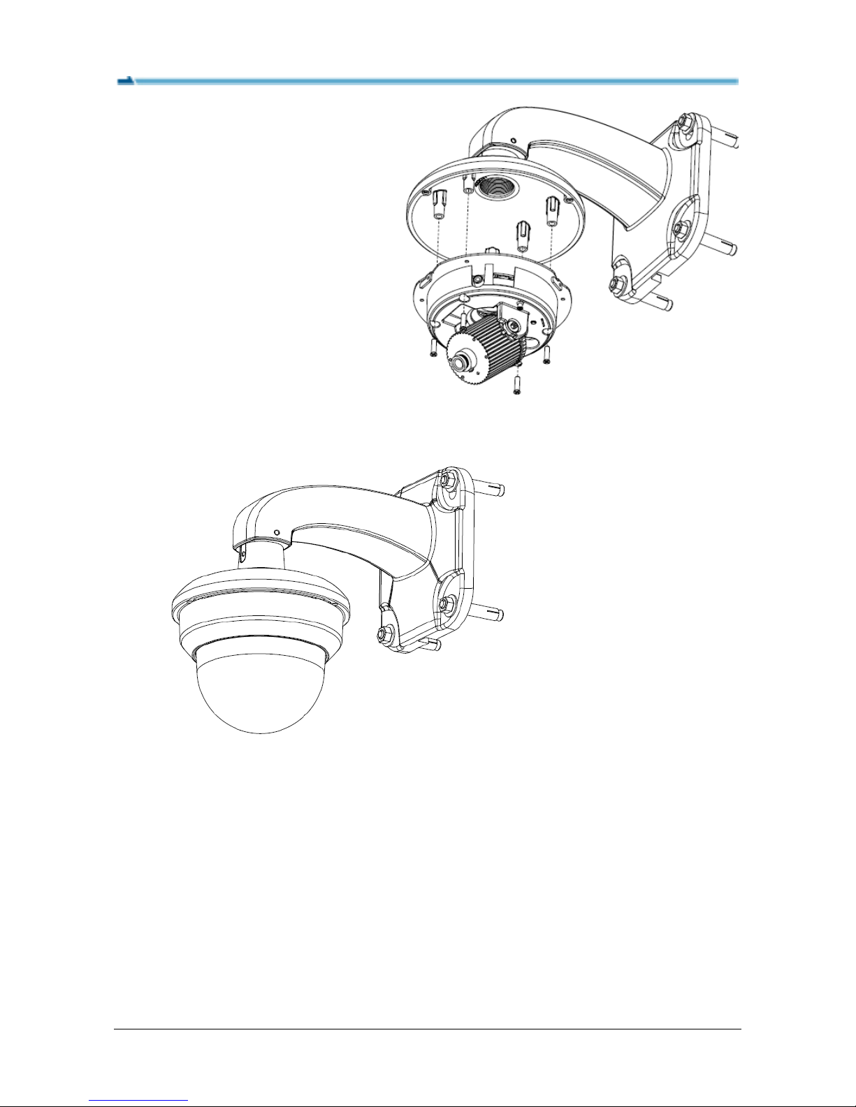
3. Attach the camera to the dome
cap using four M4x20 flathead
machine screws (supplied with
the camera).
4. Adjust the lens to the desired angle.
5. Re-attach the inner liner and the dome cove.
8
Page 9
Mounting Installation Guide
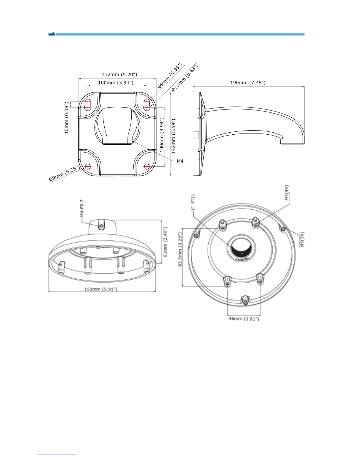
Dimensions – SAB755
9
Page 10
Mounting Installation Guide
5. Pendant Mount
Before beginning the following procedure, please make sure to have these items
ready:
Dome Cap
(SAB755M)
M4x20 flathead machine
screw x4 (supplied with the
camera)
Pendant pipe
(User-supplied)
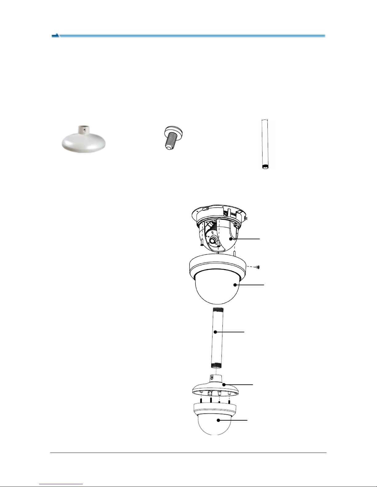
1. Remove the dome cover and the
inner liner.
Loosen the screw(s) that secure the
dome cover to remove the dome
cover. Then remove the inner liner.
2. Use appropriate adapter to connect
your pendant pipe to the dome cap.
Attach the camera to the dome cap
using four M4x20 flathead machine
screws (supplied with the camera).
Dome Cover
Inner Liner
Pipe
Dome Cap
Dome Cover
10
Page 11
Mounting Installation Guide
11
3. Adjust the lens to the desired
angle before next step.
4. Re-attach the inner liner and dome cover.
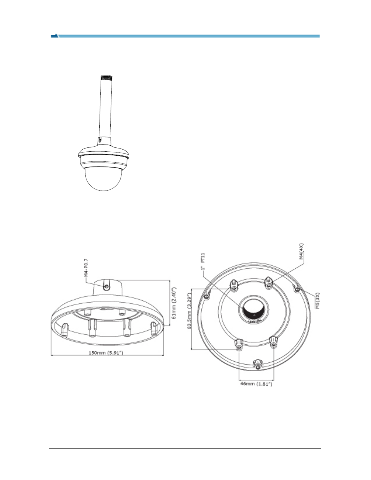
Dimensions – SAB755M
 Loading...