

Page 1

User
Manual
201511 316 A1
Mini Outdoor IR Dome Network Camera
NOD316
Page 2

1
Table of Contents
1 Product Overview 4
1.1 Physical Characteristics 4
2 Installation 6
2.1 Package Content 6
2.2 Installation 6
2.2.1 Checking Appearance 6
2.2.2 Disassembling the Camera 7
2.2.3 Wiring the Camera 7
2.2.4 Mounting the Camera 8
2.2.5 Desiccant Placement 9
2.2.6 Adjusting the Camera Position 10
3 Connection 11
3.1 Network Topology 11
3.2 System Requirements 11
3.3 Connecting Process 12
3.3.1 Default IP address 12
3.3.2 Connecting from a computer & Viewing Preparation 12
3.4 IP Finder 16
4 Administration and Conguration 17
4.1 Live View 17
4.2 Conguration 19
4.2.1 Encode 19
4.2.2 Image 22
4.2.3 Video 26
4.2.4 Network 27
4.2.5 System 35
4.2.6 Account 38
4.2.7 Event Source 40
4.2.8 Event Handler 49
Appendix: Specications of Mini Outdoor Dome Camera 53
Page 3
2
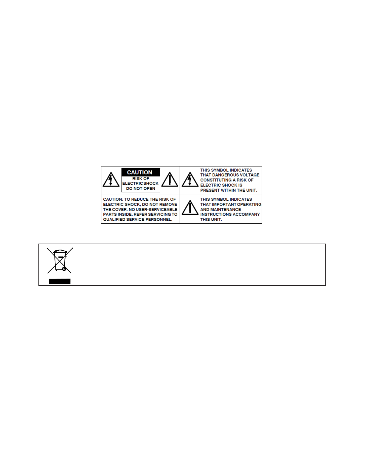
WARNING
●This camera operates at PoE (IEEE 802.3af Class 3) only.
●Installation and service should be performed only by qualied and experienced technicians and comply with all local
codes and rules to maintain your warranty.
●To reduce the risk of re or electric shock, do not expose the product to rain or moisture.
●Wipe the camera with a dry soft cloth. For tough stains, slightly apply with diluted neutral detergent and wipe with a dry
soft cloth.
●Do not apply benzene or thinner to the camera, which may cause the surface to be melted or lens fogged.
●Avoid aligning the lens with extremely bright objects (e.g., light xtures) for long periods of time.
● Although this camera is waterproof and suitable for both indoor and outdoor usages, please do not sink the camera into
water. Contact your dealer in case of sunk.
●Avoid operating or storing the camera in the following locations:
• Extremely humid, dusty, or hot/cold environments (recommended operating temperature: -40°C to +50°C)
• Close to sources of powerful radio or TV transmitters
• Close to uorescent lamps or objects with reections
• Under unstable or ickering light sources
WEEE (Waste Electrical and Electronic Equipment). Correct disposal of this product (applicable in the
European Union and other European countries with separate collection systems). This product should be
disposed of, at the end of its useful life, as per applicable local laws, regulations, and procedures.
Page 4

3
FCC Compliance Statement
Information to the user: This unit has been tested and found to comply with the limits for a Class B
digital device pursuant to Part 15 of the FCC Rules. Operation is subject to the following two conditions:
(1) this device may not cause harmful interference, and (2) this device must accept any interference
received, including interference that may cause undesired operation. These limits are designed to provide
reasonable protection against harmful interference in a residential installation. This unit generates, uses, and can radiate
radio frequency energy and, if not installed and used in accordance with the manual, may cause harmful interference to radio
communications. However, there is no guarantee that interference will not occur in a particular installation.
If this unit does cause harmful interference to radio or television reception, which can be determined by turning the unit o
and on, the user is encouraged to try to correct the interference by one or more of the following measures:
●Reorient or relocate the receiving antenna.
●Increase the separation between the unit and receiver.
●Connect the unit to an outlet on a circuit dierent from that to which the receiver is connected.
●Consult the dealer or an experienced radio/TV technician for help.
CE Statement
Operation is subject to the following two conditions: (1) this device may not cause harmful interference,
and (2) this device must accept any interference received, including interference that may cause undesired
operation. The manufacturer declares that the unit supplied with this guide is compliant with the essential
protection requirements of EMC directive and General Product Safety Directive GPSD conforming to
requirements of standards EN55022 for emission, EN 55024 for immunity, EN 300 and EN 328 for WIFI.
Caution
Changes or modications not expressly approved by the party responsible for compliance could void the
user’s authority to operate the unit.
Page 5
4
1 Product Overview
1.1 Physical Characteristics
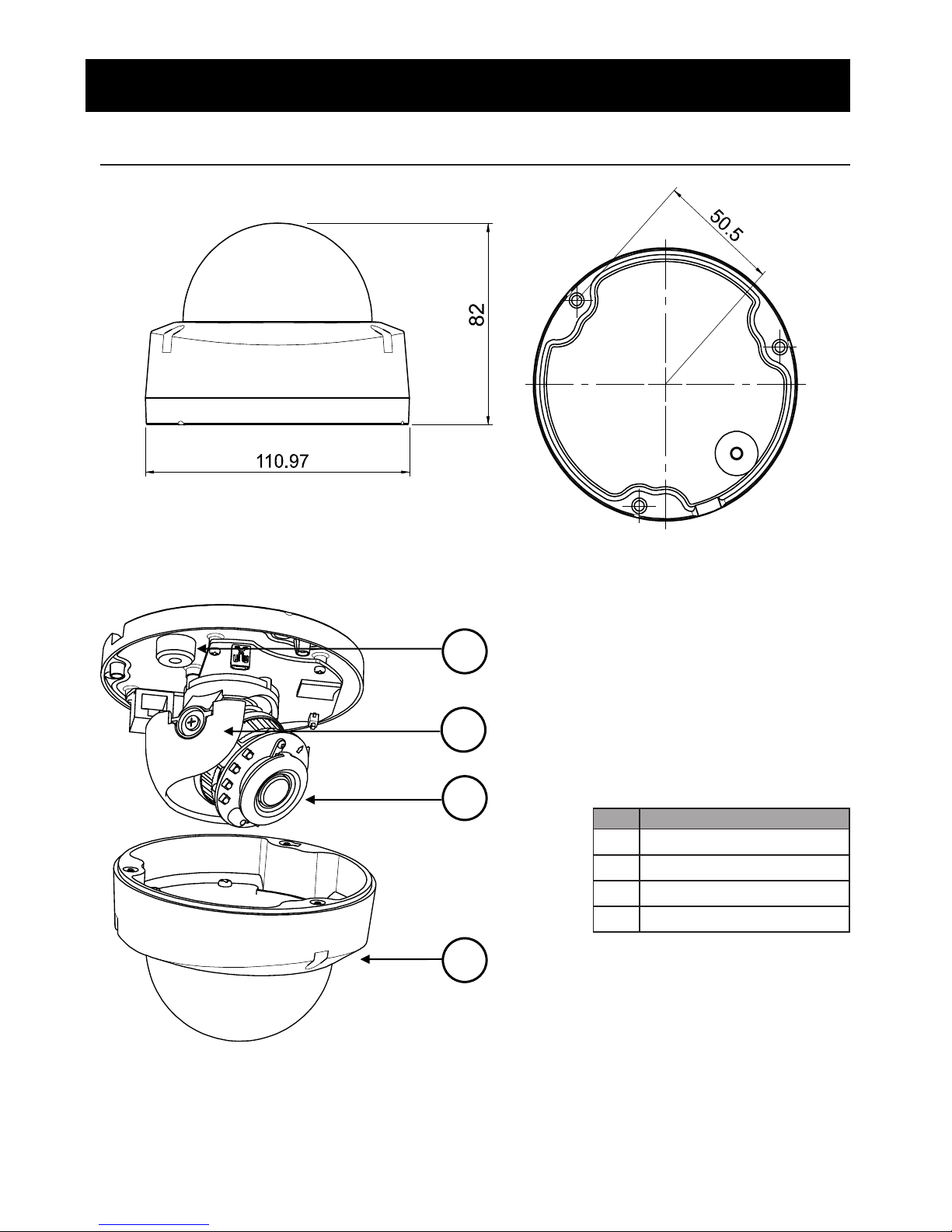
Unit: mm
Figure 1 - 1: Physical Dimension
Table 1 - 1: Pictorial Index Denition
No Name
1 Conduit Hole
2 Inner Liner
3 Camera Body
4 Top Cover
Figure 1 - 2: Pictorial Index
1
4
3
2
Page 6
5
C
B
A
D
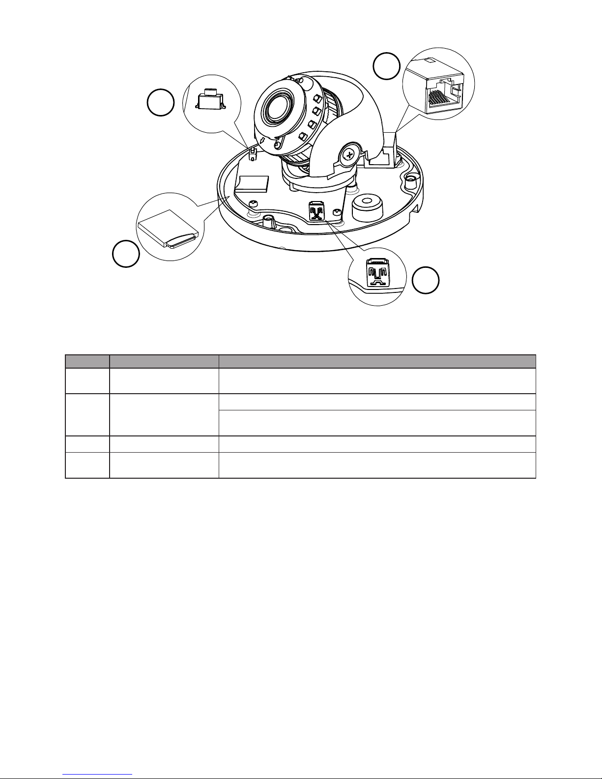
Figure 1 - 3: Internal Interface Pictorial Index
No Interface Description
A RJ-45 Ethernet PoE Port
Insert an Ethernet cable into the port for network connection as well as PoE
(Power over Ethernet) capability.
B Reset & Default Button
Press the button for below 1 second to reboot the camera.
Press the button for 6 seconds to restore the camera’s settings back to the factory
default.
C Micro SD card slot Insert a micro SD card into the slot for recording and le storage.
D Mini USB Port
Connect with USB to RJ-45 adaptor for real time image preview, which is useful
for installer to adjust a desired eld of view during installation.
Table 1 - 2: Internal Interface Index Denition
Page 7

6
2 Installation
2.1 Package Content
2.2 Installation
Check if everything in the packing box matches to the order form and the packing slip. All items listed below should be
included in the packing box.
•Network Mini Outdoor Dome Camera x1
•Printed Quick Guide x1
•Guide Pattern x1
•Torx Wrench x1
•Plastic Anchors x3
•Tapping Screws x3
Please contact your dealer if any of the items is lost.
Following tools might help you complete the installation:
•a drill
•screwdrivers
•wire cutters
2.2.1 Checking Appearance
When rst unboxing, please check whether if there is any visible damage to appearance of the camera and its accessories.
The protective materials used for the packaging should be able to protect the camera from most of accidents during
transportation. Please remove the protective materials of the camera when every item is properly checked in accordance
with the list in “Package Content”.
Page 8
7
2.2.2 Disassembling the Camera
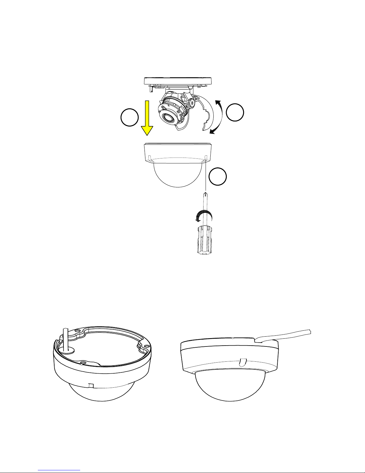
Please refer to the steps with gures below for correct disassembling order.
1. Loosen the 3 torx screws counter-clockwise by the torx wrench.
2. Gently pull the top cover downward to take it apart from the camera body.
3. Lift to open the inner liner coating on the lens for adjustment later.
1
2
3
Figure 2 - 1: Disassembling the Camera
2.2.3 Wiring the Camera
After disassembling, the PoE RJ-45 Ethernet port is visible on the camera body for user to connect an Ethernet cable for both
power supply and network connectivity purposes. The Ethernet cable can be arranged by side conduit or bottom conduit
manner. The following gures are for reference on how to arrange 2 methods.
Figure 2 - 2: Bottom Conduit Manner Figure 2 - 3: Side Conduit Manner
Page 9
8
2.2.4 Mounting the Camera
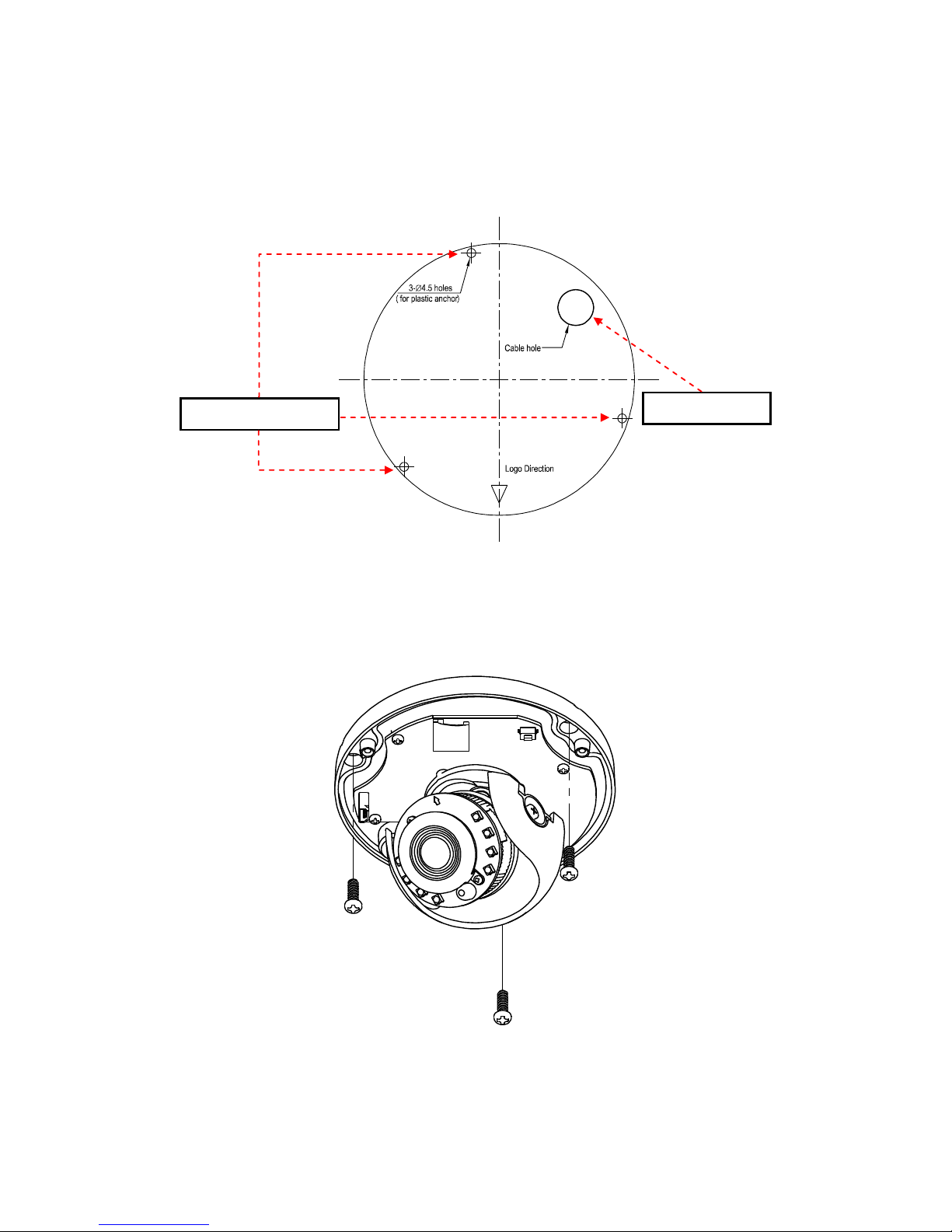
Step 1. Mounting Preparation
Paste the included guide pattern onto a wall/ceiling where the IP camera is about to be located, and drill 3 hole patterns in
accordance with the indications on the guide pattern (3-Ø4.5 Holes) followed by hammering the 3 plastic anchors into the
drilled holes. Also, drill another hole for button conduit cable entry as the indication of “Cable hole” (Ignore drilling cable hole
if applying side conduit manner).
Cable Entry Hole
Plastic Anchors Holes
Figure 2 - 4: Guide Pattern
Step 2. Mounting the Camera
Place the camera on the predened surface and fasten the 3 tapping screws clockwise into the plugged plastic anchors
securely to x the camera onto the location.
Figure 2 - 5: Mounting the Camera
Page 10
9
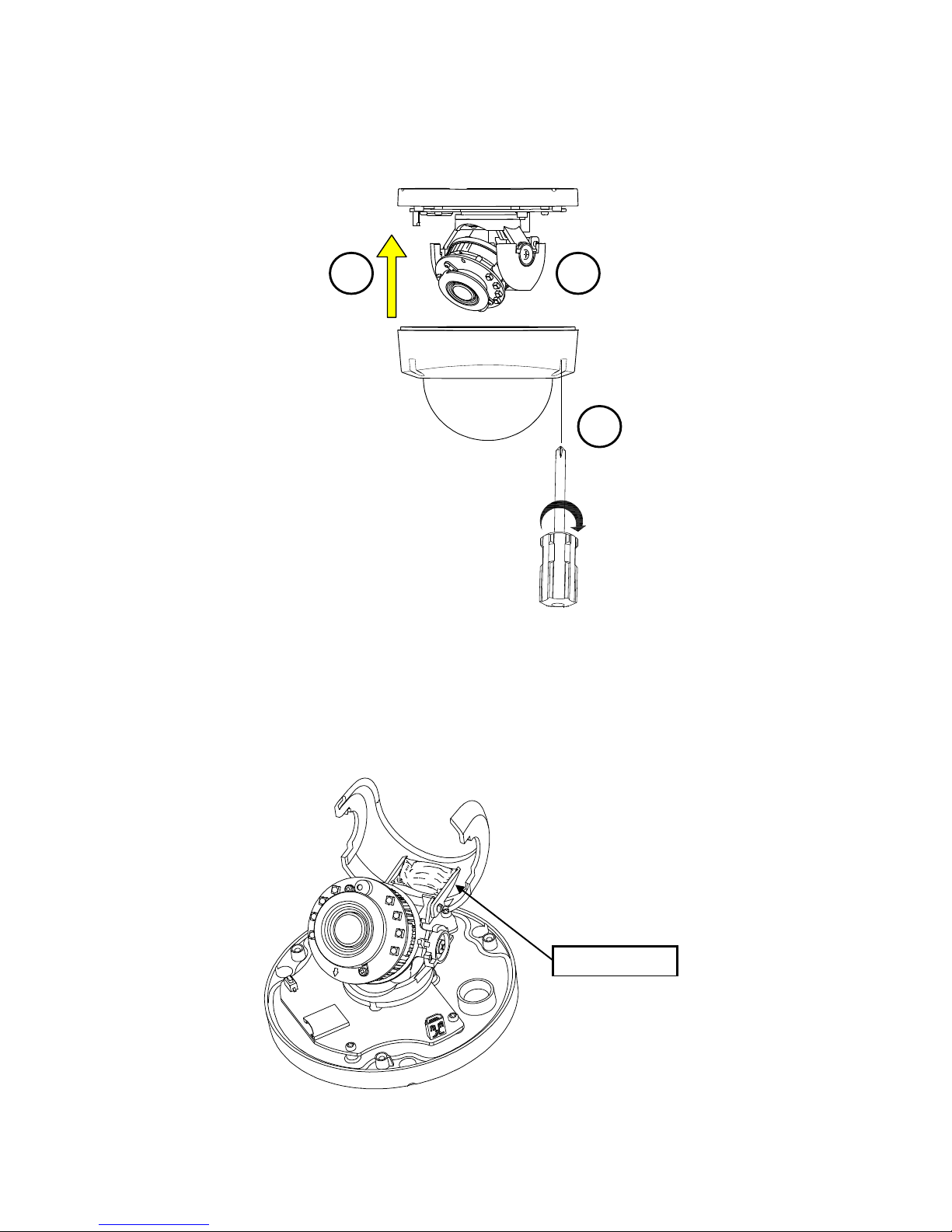
Step 3. Assembling the Camera
Please refer to the following steps with gure for correct assembling order.
1. After adjustment, t the inner liner over the camera lens until it clicks into the place.
2. Gently put the top cover upward to attach with the camera body.
3. Fasten the 3 torx screws with the camera body clockwise to complete the mounting.
1
2
3
Figure 2 - 6: Assembling and Completing Camera Mounting
2.2.5 Desiccant Placement
For the sake of lessening the moisture effects within the camera, it is strongly recommended to have a desiccant pack
adhered to the internal side of the inner liner as shown below prior to completing the mounting procedure.
Desiccant Pack
Figure 2 - 7: Desiccant Placement
Page 11
10
2.2.6 Adjusting the Camera Position
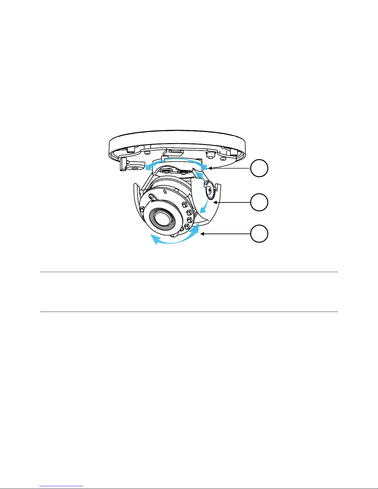
The camera has three axes to adjust eld of view for dierent applications. While screening live view on your monitor, adjust
the axes by the procedures below simultaneously for desired coverage of eld of view.
•Pan Adjustment (A)
Rotate the lens base until satised with the eld of view. Please DO NOT rotate over the default limit.
•Horizontal Rotation (B)
Rotate 3D assembly in the lens, but DO NOT turn assembly more than the limit as this may have the internal cables
twisted, disconnected, or broken.
•Tilt Adjustment (C)
Tilt the camera lens within the certain range (27° - 90°) to your desired eld of view.
A
B
C
Figure 2 - 8: Adjusting the Camera Position
Caution
Limitation for three axes position:
•Pan range : >360°
•Rotate range : ±175°
•Tilt range : 27° ~ 90°
Page 12
11
3.1 Network Topology
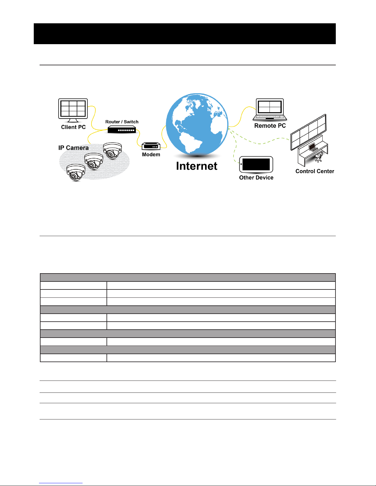
The camera, which is equipped with Ethernet RJ-45 network interface, can deliver live view image in real time via both
Internet and Intranet manners. Please refer to the skeleton drawings shown below for understanding.
Figure 3 - 1: Network Topology
3 Connection
Below table lists the minimum requirement to implement and operate the camera. No hardware/software component
inferior to the requirements is recommended.
Table 3 - 1: System Requirements
System Hardware
CPU Intel Pentium 4 2.4GHz or equivalent
RAM 1 GB or above
Display NVIDIA GeForce 6 Series or ATI Mobility Radeon 9500
System Software
Operating System Microsoft Windows XP, Windows Vista, Windows 7 or above
Browser Microsoft Internet Explorer 8 ~ 10, Chrome, Firefox, Safari
Unit
Power Supply DC 12V / PoE (IEEE 802.3af Class 3)
Networking
Wired* 10/100BASE-T Ethernet (RJ-45 connector)
*A switch is required for surveillance on multiple cameras.
Note All the installation and operations should comply with your local electricity safety rules.
Caution
When adopting PoE, this camera is to be connecting only to PoE networks without routing to
heterogeneous devices.
3.2 System Requirements
Page 13
12
3.3.1 Default IP address
Since this is a network-based unit, an IP address must be assigned at the very first. The unit’s default IP address is
192.168.1.30 and sub mask is 255.255.255.0. However, if you have a DHCP server in your network, the unit would obtain
an IP address automatically from the DHCP server so that you don’t need to change the camera’s IP address. But be sure to
enable DHCP in "Network Settings".
3.3.2 Connecting from a computer & Viewing Preparation
Connecting from a computer
1. Make sure the unit and your computer are in the same subnet.
2. Check whether if the networking available between the unit and the computer by executing ping the default IP address.
To do this, simply start a command prompt (Windows: from the Start Menu, select Program. Then select Accessories
and choose Command Prompt.), and type “Ping 192.168.1.30”. If the message “Reply from…” appears, it means the
connection is available.
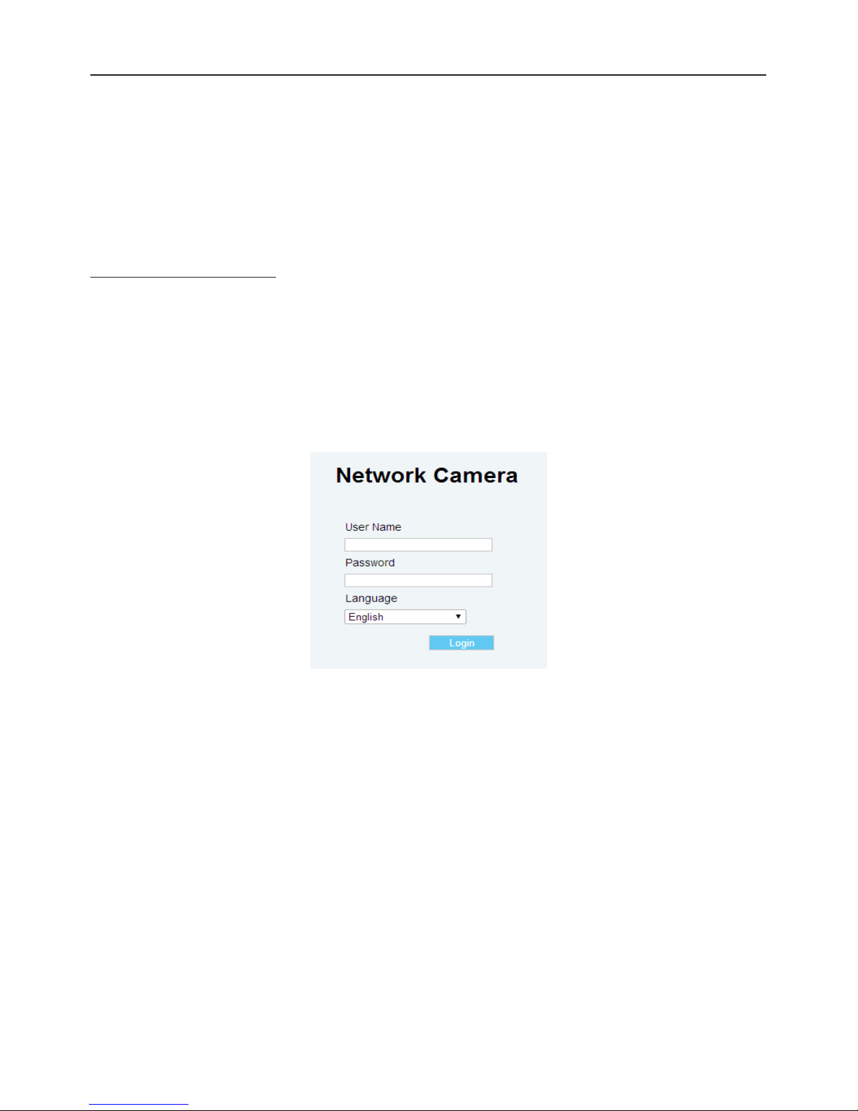
3. Start a browser e.g. Internet Explorer and enter IP address: 192.168.1.30. A login window should pop up. In the window,
enter the default user name: admin, password: 1234 and select a user interface language to log in.
Further administration on the unit can be found in “4. Administration and Conguration".
Figure 3 - 2: Login Window
3.3 Connecting Process
Page 14
13
Viewing Preparation
Images of the unit can be viewed through Microsoft Internet Explorer 8 or above. Before viewing, follow these steps to
enable the display.
1. Enable Cookies as instructions below
In Internet Explorer, click Internet Options on the Tools menu.
On the Privacy tab, move the settings slider to Low or Accept All Cookies.
Click OK.
2. When a proxy server is used, click Internet Options on the Tools menus of Internet Explorer, select Connect tab, click
LAN button, and set proxy server.
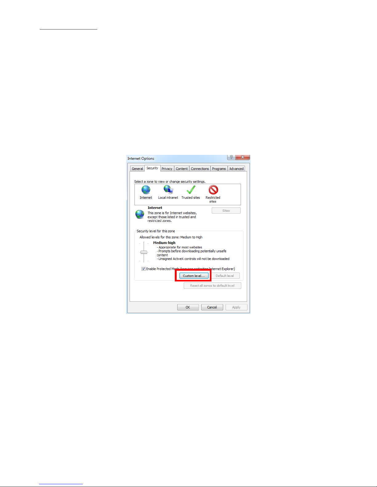
3. Change Security in Internet options as instructions below
On tool menu, click Internet Option.
Press the Security tab.
If the camera operates inside of the intranet, click the Intranet icon.
If the camera operates outside of the intranet, click the Internet icon.
Click Custom Level. This will open the Security Settings – Internet Zone screen.
Figure 3 - 3: Security Settings 1/4
Page 15
14
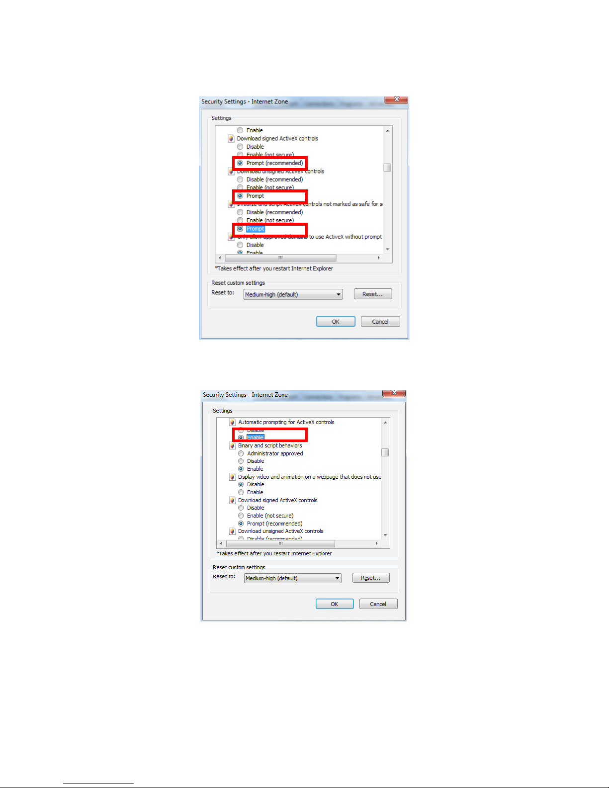
Scroll down to the ActiveX controls and plug-ins radio buttons and set as follows:
【Download signed ActiveX controls
】
Prompt (recommended)
【
Download unsigned ActiveX controls
】
Prompt
【
Initialize and script ActiveX not marked as safe for scripting
】
Prompt
Figure 3 - 4: Security Settings 2/4
【
Automatic prompting for ActiveX controls
】
Enable
Figure 3 - 5: Security Settings 3/4
Page 16
15
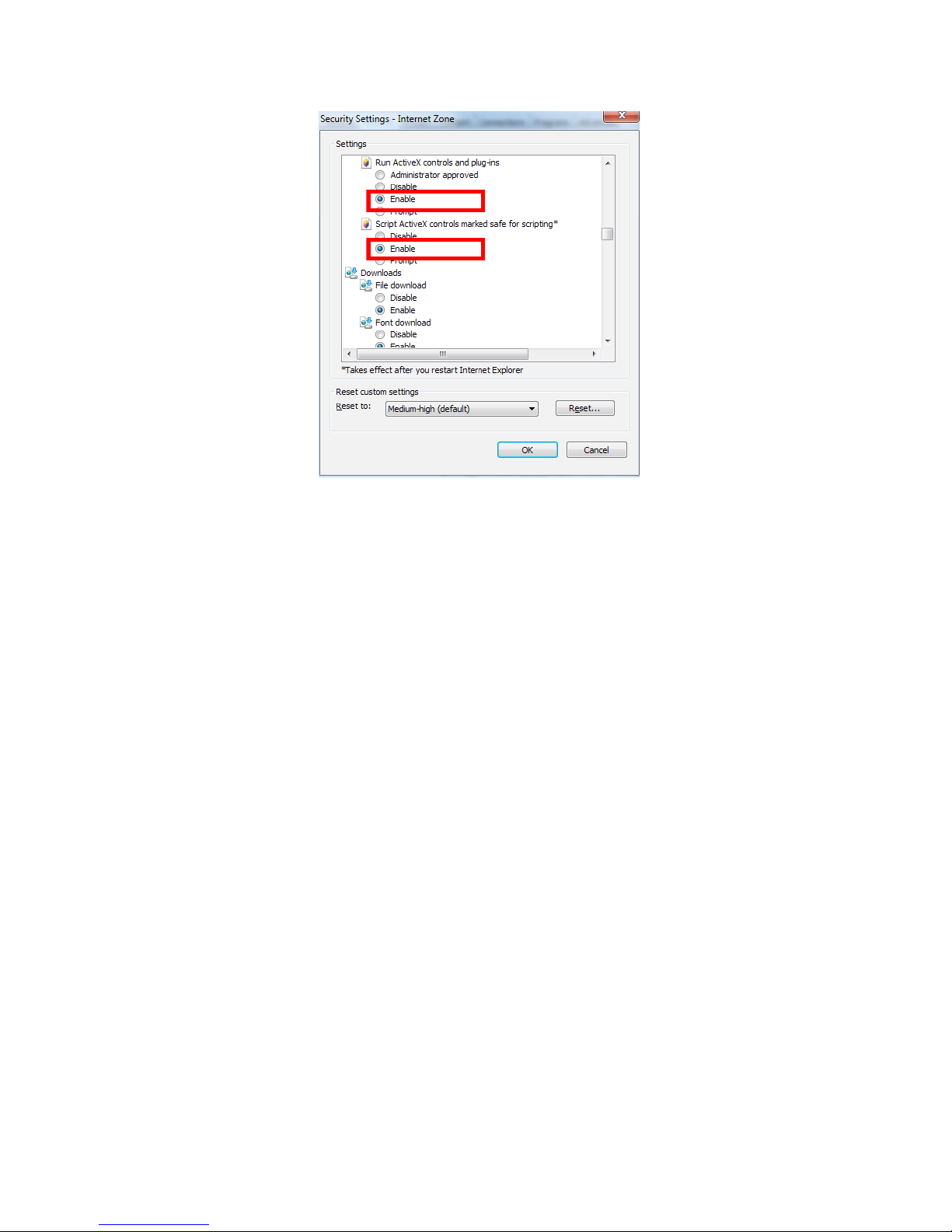
【
Run ActiveX controls and plug-ins
】
Enable
【
Script ActiveX controls marked safe for scripting*
】
Enable
Figure 3 - 6: Security Settings 4/4
Press OK to save the settings.
Close all Microsoft Internet Explorer Windows and restart a new window. This will allow the new settings taking eect.
Type your setting IP address into the browser.
Then you should be able to see the camera image screen.
Page 17
16
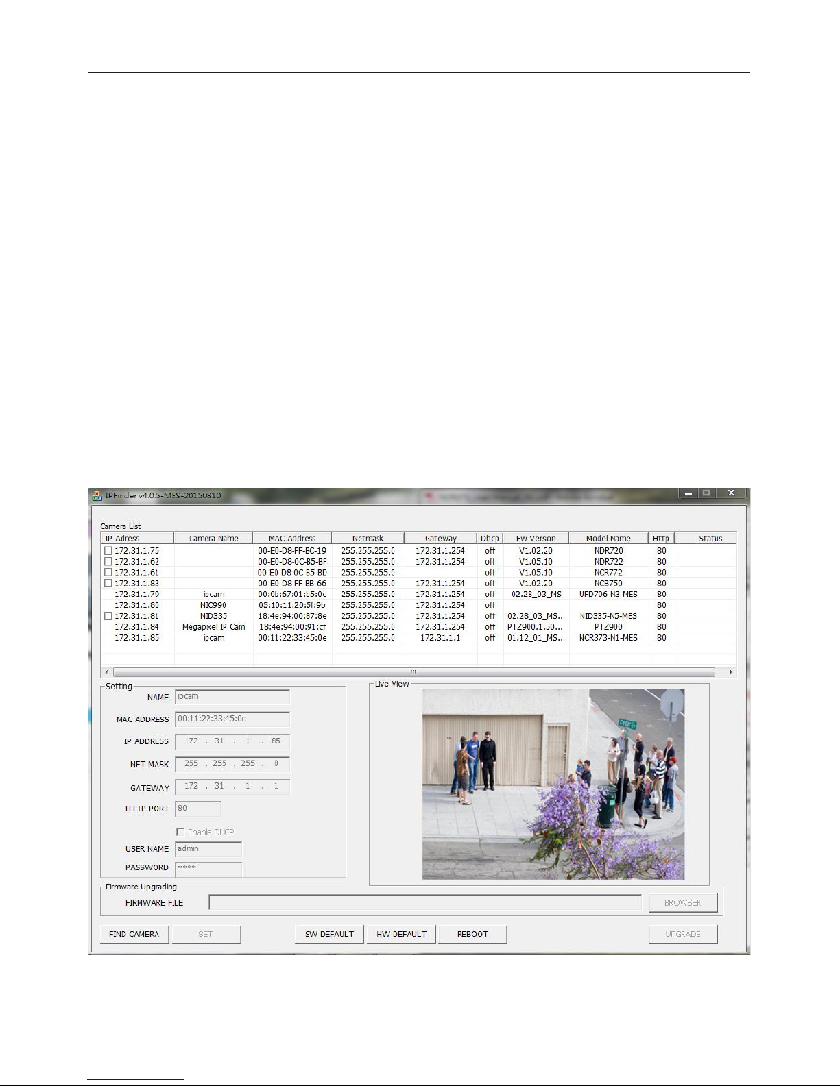
IP Finder is a utility program that helps users to locate the unit in local area network that computer is connected to. Please
note that IP Finder works only in Microsoft Windows XP, Microsoft Windows Vista, and Microsoft Windows 7 or above. Steps to
get the utility program running are listed below.
1. Download IP Finder from MESSOA Website to the computer.
2. Double click on IPFinder.exe in the IP Finder folder, and the IP Finder window should pop out.
3. The window would list information of units in operation at present. Press FIND CAMERA to nd more units.
4. Locate and double-click one of the cameras in the list you want to congure the network settings. If you have multiple
cameras connected to your local network, locate the MAC address on the camera to distinguish the target camera from
others.
5. Congure the following settings as needed.
• NAME: Enter a descriptive name for the camera.
• NETWORK SETTINGS: If you have a DHCP server on your network to assign IP addresses to network devices, enable
the DHCP option. Otherwise, manually enter the IP ADDRESS, NET MASK and GATEWAY values.
• USERNAME & PASSWORD: Manually setup preferred username and password.
• SET: Whenever you make revision of camera settings, click “SET” to take effect.
• SW DEFAULT: To perform the factory defaults excluding network settings of the selected camera.
• HW DEFAULT: To perform the factory defaults of the selected camera.
• REBOOT: To reboot the selected camera.
Click Save to enable the settings and click Exit to exit the utility.
Figure 3 - 7: IP Camera Finder
3.4 IP Finder
Page 18
17
4 Administration and Conguration
4.1 Live View
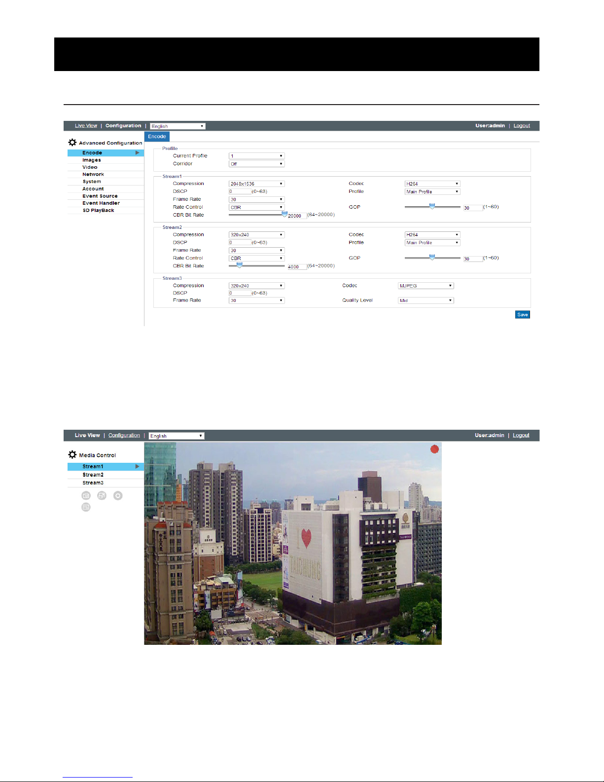
Figure 4 - 1: First Login Page
After accessing and login to the IP address of the camera, the screen will be shown as the screenshot above. There’re 2 main
options on the upper left side: “Live View” and “Conguration”. The upper right corner, on the other hand, indicates the
current user level and the “Logout” option allows user, by clicking, to log out. In addition, the dropdown menu beside the
Conguration is for UI language switch. We mainly focus on Live View part in this chapter and will detail conguration in the
“4.2 Conguration” chapter later.
Figure 4 - 2: Live View
After clicking “Live View”, user will be led to a real-time live view screen. The “Stream1, 2, 3” are available for user to switch
among each stream conguration for better adaptation in dierent network applications, for which you may refer to the
latter chapter “Encode” for more details.
Page 19
18
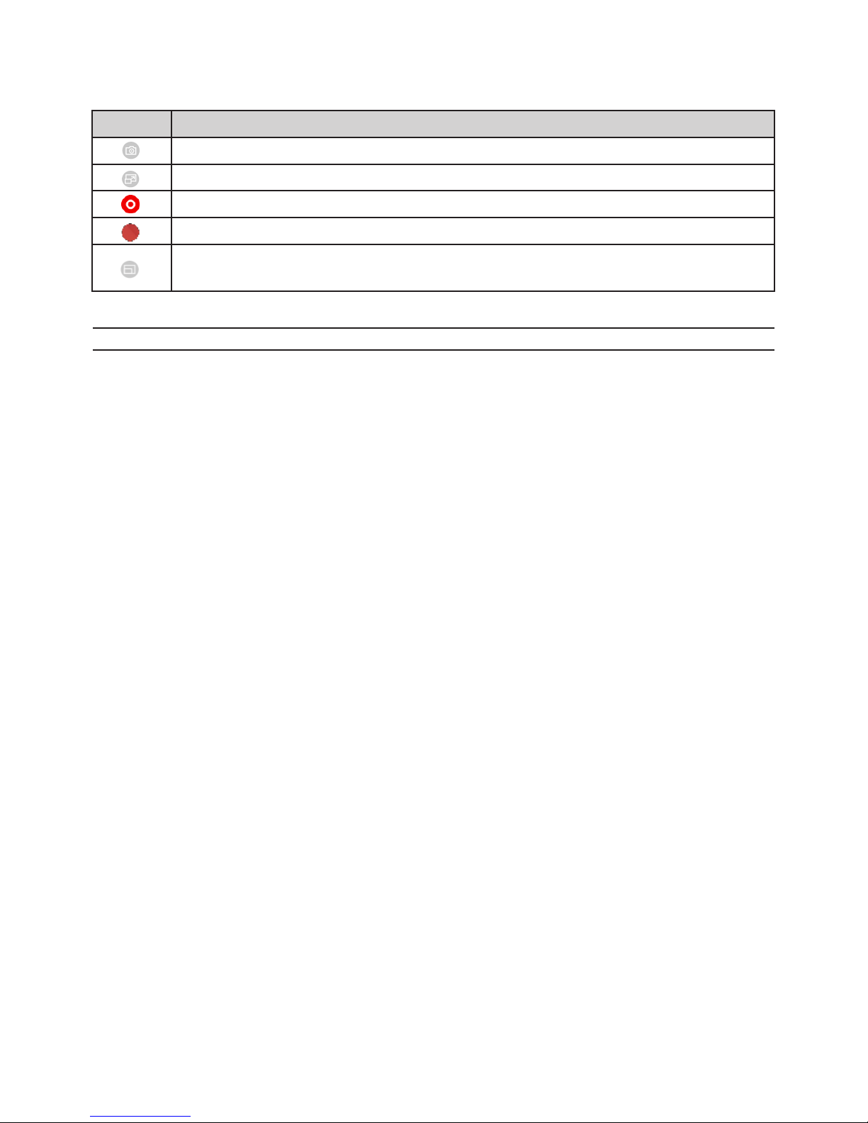
The following icons within the table, which are in the left-side window and on the top of Live View screen, are for several
functions activation and statuses indication. Please refer to the detailed denitions below for more understanding.
Icon Denition
The “Snapshot” button is for taking a snapshot saved in a user-preferred le path.
The “Full Screen” button is for users to display a full screen live view display. (Press Esc to back)
The “Manual Recording” button is for users to activate recording function.
The icon on the upper-right corner indicates live view video is being recorded.
The “Zoom Control” button is for users to manipulate zoom magnication. Place the mouse cursor over the
live view scree followed by using the scroll wheel to perform zoom in or zoom out.
Table 4 - 1: Live View Icon Denition
Note Keep the zoom level of applied browser as 100% to display a normal live view.
Page 20
19
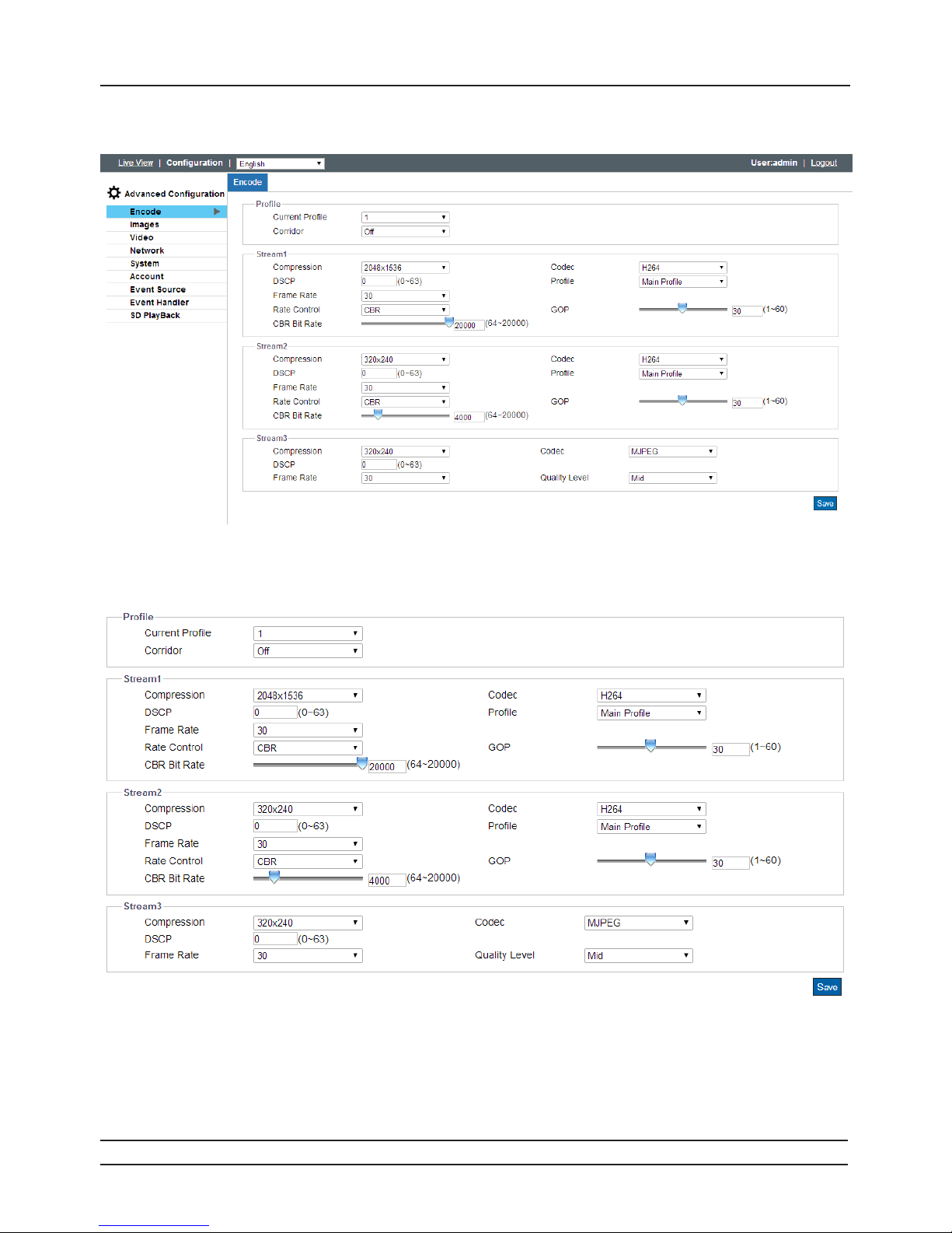
After clicking the “Conguration” option, the screen will be shown as below with several menu options for users to congure
on the left side. We will thoroughly introduce them one by one in the following chapters.
Figure 4 - 3: Congure
4.2.1 Encode
Figure 4 - 4: Encode
By default, there are up to 3 profiles to be selected from and each profile contains 3 streams individually for further
conguration. User is strongly suggested to dene dierent settings under each stream to exibly bring about better video
transmission for varied network environments and applications. The detailed congurations for each stream are explicitly
described as the following table:
Note Please click “Save” button to have your settings taken eect.
4.2 Conguration
Page 21

20
Table 4 - 2: Edit Prole Options
Item Option Description
Corridor
ON
OFF
In certain of the vertical oriented shape applications, e.g., sideway, aisle,
corridor, because of the attribute that requires more details in vertical areas,
the prevailed 16:9 aspect ratio is not that appropriate and large portion of
bandwidth are wasted in landscape field of view. Consequently, in order
to optimize the image result for corridor-like applications, click “On” to
enable this function so that the image will be rotated back 90 degrees to
a 9:16 aspect ratio that perfectly fits portrait-like environments, reducing
bandwidth and storage wastes.
Compression
QXGA(2048×1536) , Full HD(1920×1080),
QuadVGA(1280×960) , HD(1280×720),
SVGA(800×600), VGA(640×480), VGA
Wide(640x360), QVGA(320x240), (320x176)
QXGA(2048×1536) is the highest resolution
(320x176) is the lowest resolution.
Codec
MJPEG
H.264
MJPEG: Each video frame is individually compressed as single jpeg image
with full-scale contents itself and can be retouched freely with ease.
However, due to completeness of each frame, it brings about larger le size
and thus easily tends to lose frames under limited network bandwidth.
H.264: The latest best-renowned video compression format, it adopts
intelligent technology to record variation in each frame rather than record
each full frame. As a result, less network bandwidth it requires and le size is
prone to be smaller compared with MJPEG.
DSCP 0 ~ 63
To classify and manage network trac and provide quality of service (QoS)
on modern IP networks, Differentiated Services Code Point (DSCP) is a
computer networking architecture that specifies a resource allocation to
each device on a priority-based pattern for ideal bandwidth management.
The bigger value, the higher priority it will be.
Prole
Main
High
Baseline
There’re 3 kinds of proles for H.264 codec and the compression ratio with
protocol for each type are different. Users may choose a proper one for
desired applications or contact IT personnel for more information.
Frame Rate
NTSC: 1~30
PAL: 1~25
The utmost fps settings for 2 systems varies as the following:
NTSC:
H.264/MJPEG single stream: 2048×1536 to 320x176@30fps
PAL:
H.264/MJPEG single stream: 2048×1536 to 320x176@25fps
Rate Control
CBR
CVBR
Choose one of the Rate Control modes depending on dierent situations.
Higher bit rate value will result in better quality with bigger file size and
thus consume more network bandwidth, while lower bit rate value, instead,
has slighter loading on network bandwidth due to smaller le size but with
inferior image quality.
GOP (Group Of
Pictures) Length
NTSC: 1~60
PAL: 1~50
Select the GOP length number from NTSC: 1 to 60 / PAL: 1 to 50. Less number
means the distance between 2 I-frames is smaller, which needs more
network bandwidth with better image. By contrast, larger number consumes
less bandwidth but is hard to be recovered. The available length number
options of GOP will vary based on frame rate settings.
M-JPEG Quality
Level
Low/Mid/High
While “Low” produces the highest image quality, it increases the le size; on
the other hand, “High”, the lowest image quality, decreases the le size.
Page 22

21
Table 4 - 3: Correlations of Resolution/Streams/FPS/Codecs – NTSC/PAL
Stream 1 (H.264/MJPEG) Stream 2 (H.264/MJPEG) Stream 3 (H.264/MJPEG)
2048x1536@30/25fps
1920x1080@30/25fps
1280x960@30/25fps
1280x720@30/25fps
800x600@30/25fps
640x480@30/25fps
640x360@30/25fps
320x240@30/25fps
320x176@30/25fps
OFF
800x600@30/25fps
640x480@30/25fps
640x360@30/25fps
320x240@30/25fps
320x176@30/25fps
OFF
800x600@30/25fps
800x600@30/25fps
640x480@30/25fps
640x360@30/25fps
320x240@30/25fps
320x176@30/25fps
OFF
800x600@30/25fps
640x480@30/25fps
640x360@30/25fps
320x240@30/25fps
320x176@30/25fps
OFF
640x480@30/25fps
640x480@30/25fps
640x360@30/25fps
320x240@30/25fps
320x176@30/25fps
OFF
640x480@30/25fps
640x360@30/25fps
320x240@30/25fps
320x176@30/25fps
OFF
640x360@30/25fps
640x360@30/25fps
320x240@30/25fps
320x176@30/25fps
OFF
640x360@30/25fps
320x240@30/25fps
320x176@30/25fps
OFF
320x240@30/25fps
320x240@30/25fps
320x176@30/25fps
OFF
320x240@30/25fps
320x176@30/25fps
OFF
320x176@30/25fps
320x176@30/25fps
OFF
320x176@30/25fps
OFF
Page 23
22
4.2.2 Image
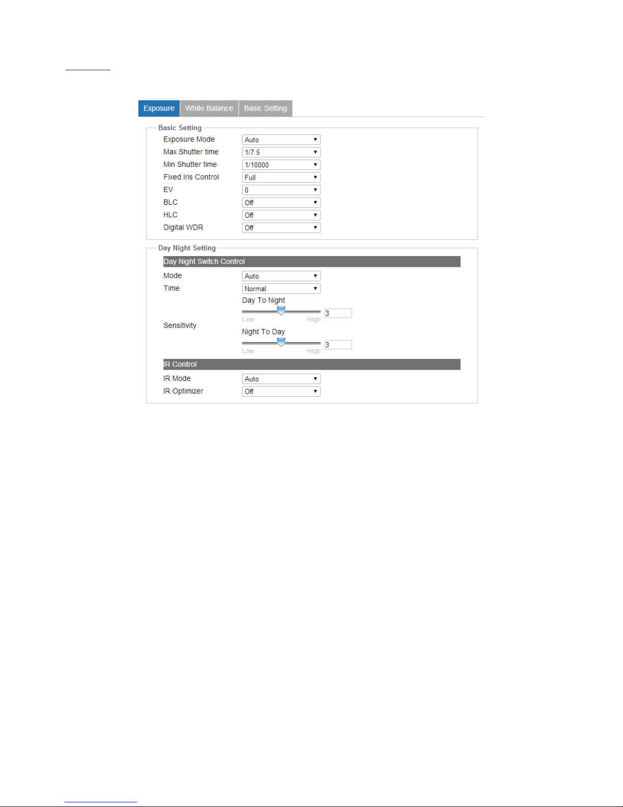
Exposure
This section mainly allows user to control the settings pertaining to exposure mode and day night modes.
Figure 4 - 5: Exposure
Basic Settings
●Exposure Mode
There are 4 modes to select from as follows:
• Auto: with certain pre-settings, the camera automatically determines the correct exposure for pictures without user input
settings for further exposure before taking videos.
• Flickerless: this mode allows camera to override the shutter speed, which will help avoid from the interference of uorescent
lights in some environments.
• Shutter Priority: it enables user to select a specic shutter speed for adjustment of aperture to ensure a correct and proper
exposure.
• Manual: a mode that allows user to manually control both gain value and shutter speed. It is recommended for an
experienced administrator to adopt this mode.
●Max / Min Shutter Time
• Select the minimum and maximum shutter time individually for the “Auto” exposure mode only.
●Fixed Iris Control:
• Full: the Iris will always leep fully open to maintain enough exposure.
●EV
It is the exposure compensation option telling camera by setting value from -2 to 2 for scenes to be either darker or brighter.
(Unavailable when exposure mode is Manual)
Page 24
23
●BLC
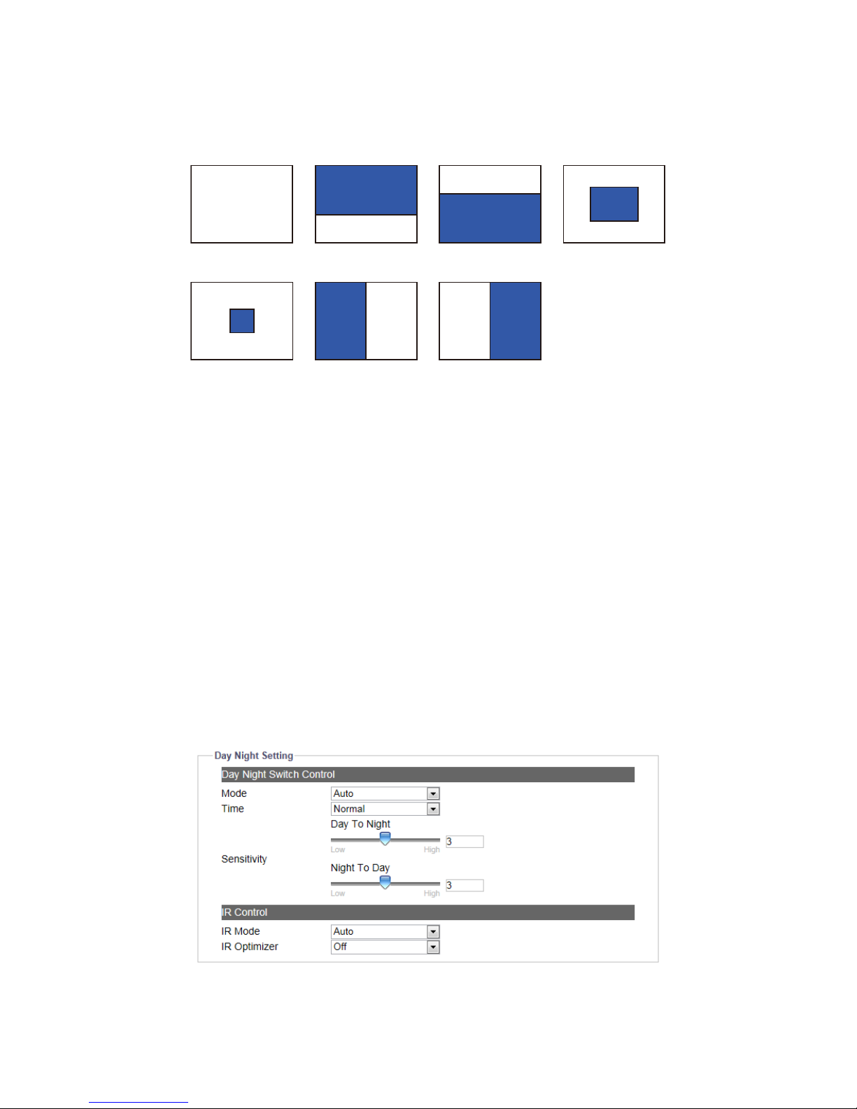
Set an area for Backlight Compensation. Backlight Compensation is a function that achieves the brightness of a selected area to
optimal image level. This function is necessary when an auto iris lens tends to close quickly due to an intense light coming from
back of object in the area wished to view, resulting in the area is too dark and dicult to see. In this case, users may set the area
corresponding to the portion wished to see. The area size illustrations are roughly as follows. (Unavailable when exposure mode
is Manual)
Upper 2/3
Left
Right
OFF
Lower 2/3 Center 1/3
Center 1/6
Figure 4 - 6: BLC Settings Illustrations
●HLC
High Light Compensation (HLC) is a function that suppresses intensied light sources in camera coverage so that image will
be free from disturbance of strong light and thus details like license plate under strong headlight can be recognized clearly.
(Unavailable when exposure mode is “Manual”)
●Digital WDR
It is intended to provide clear images even under backlight circumstances where intensity of illumination can vary excessively,
namely where there are both very bright and very dark areas simultaneously in the eld of view. WDR enables the capture and
display of both bright and dark areas in the same frame, in a way that there are clear details in both areas, i.e. bright areas are not
saturated, and dark areas are not too dark.
●Shutter Speed
Users can adjust preferred shutter speed ranging from the fastest 1/10000 second to the slowest 1/7.5 (1/6.25) second. (Available
when exposure mode is “Shutter Priority” or “Manual”)
●Gain
This option allows user to control the gain value ranging from the lowest 0 to the highest 48. Larger the value, more intensity of
lights come into the camera and vice versa. (Available when exposure mode is “Manual”)
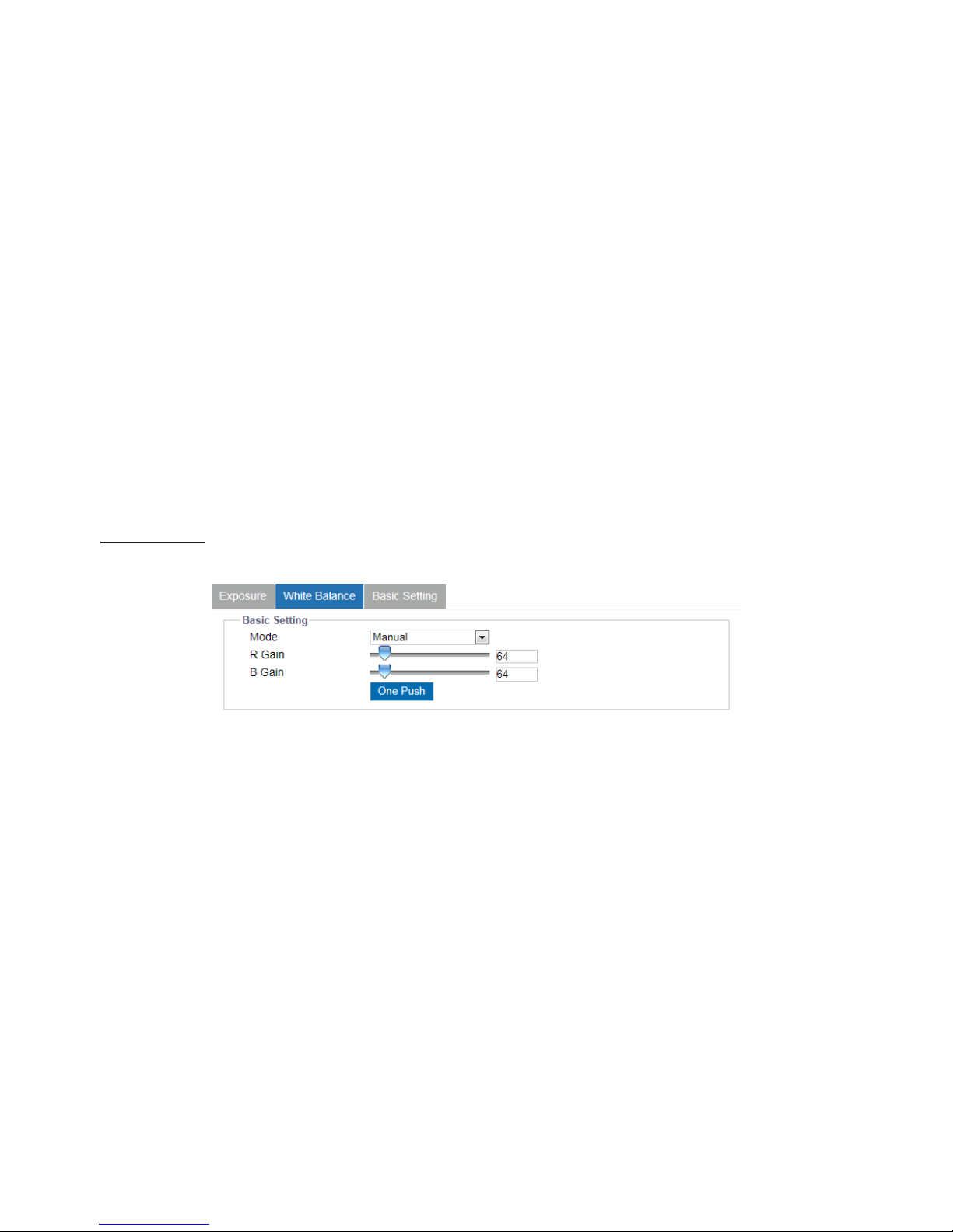
Day Night Settings
Figure 4 - 7: Day Night Setting
Page 25
24
●Day Night Switch Control – Mode
Set Day Night mode from 3 options, Auto, Color and B/W. When Color mode is selected, the camera is forced to stay in
Color mode permanently. On the other hand, the camera keeps within black and white mode when B/W is selected. Auto
simply let the camera to, based on dierent intensity of lights, switch between 2 modes automatically.
●Day Night Switch Control – Time
To set the delay (buered) time for switching between day and night modes. Fast means camera instantly switch with
nearly no delay time between day/night mode. And Slow stands for camera has a longer delay buered time prior to
switching between day/night modes. (Unavailable when exposure mode is Manual)
●Day Night Switch Control – Sensitivity
It determines the sensitivity of the day/night mode switching mechanism. Larger the value (High) represents camera is
prone to auto switch from day to night or night to day mode for minor light intensity change. On the other hand, smaller
the value (Low) indicates camera is going to switch from day to night or night to day mode on the basis of major changes
of surrounding light intensity. (Unavailable when exposure mode is Auto or Manual)
●IR Mode
Click “ON” to let camera enable IR LED permanently, and click “Auto” to let camera switch on or o IR LED based on light
intensity of dierent applications. Click “OFF” to simply turn o IR LED.
●IR Optimizer
Click “ON” to let camera enable IR optimizer, by which the intensity of IR LED will be evenly adjusted based on the focused
object along with the distance so that the events like overexposure can be avoided eciently and a better IR eect can
thus bring about. Note that “BLC” function will be disabled when IR Optimizer is activated.
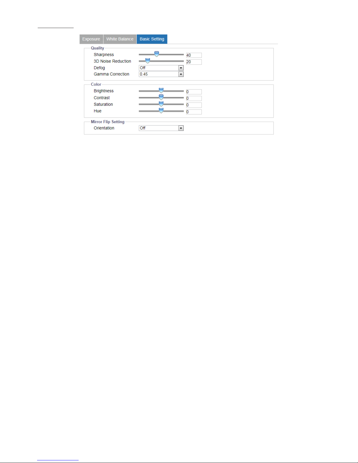
White Balance
This section allows user to set the white balance values to meet ambient conditions for best color rendition.
Figure 4 - 8: White Balance Settings
●Mode
• ATW: Auto Tracing White Balance continuously adjusts the camera color balance in accordance with any change in color
temperature simultaneously.
• Auto: it automatically controls color temperature ranging from 2500°K to 10000°K
• Manual: to manually set preferred gain values including the following:
» R (Red) Gain: it allows users to adjust red color in the image ranging from 0 to 255.
» B (Blue) Gain: it allows users to adjust blue color in the image ranging from 0 to 255.
» One Push: click this button to make the camera adjust to the proper gain values depending on the ambient
environment rapidly.
Page 26
25
Basic Setting
Figure 4 - 9: Basic Settings
●Sharpness
Increasing the sharpness value will sharpen the edges and small feature of viewing images. If the edges appear too
smooth or blurred, increase the sharpness; otherwise, decrease the sharpness. Sharpness value can be set from 0 to 100.
The 100 oers the sharpest image.
●3D Noise Reduction
It is the process of removing noises from a signal and be set from 0-100 to decrease noise on the screen. The 100 oers the
highest eect of noise reduction.
●Defog
When installed under extreme outdoor environments, camera may have inferior image coverage due to certain weather
factors, e.g., snow, frost. As a result, please select "On" to enable Defog function so that it can thaw the frost and fog from
camera for better image results.
●Gamma Correction
Set gamma correction, which matters when you need to display an image accurately on different monitor screens,
between 1 and 0.45 for better rendition in varied screens.
●Brightness
Set image brightness from level -100 to 100. The 100 provides the brightest image.
●Contrast
Set image contrast from level -100 to 100. The 100 provides the highest contrast image.
●Saturation
Increasing saturation deepens the colors of camera images, making reds redder and blues bluer. User can adjust picture
saturation level from -100 to 100. Decreasing saturation brings the image closer to a grayscale (that is, monochrome)
image. Selecting 100 provides the highest image saturation.
●Hue
Set picture hue from level -100 to 100. Selecting 100 provides the deepest hue eect.
●Orientation
Set image to be left right reversal, upside down or both by selecting “Mirror”, “Flip” and “Both” individually. Selecting “OFF”
will disable video orientation function.
Page 27
26
4.2.3 Video
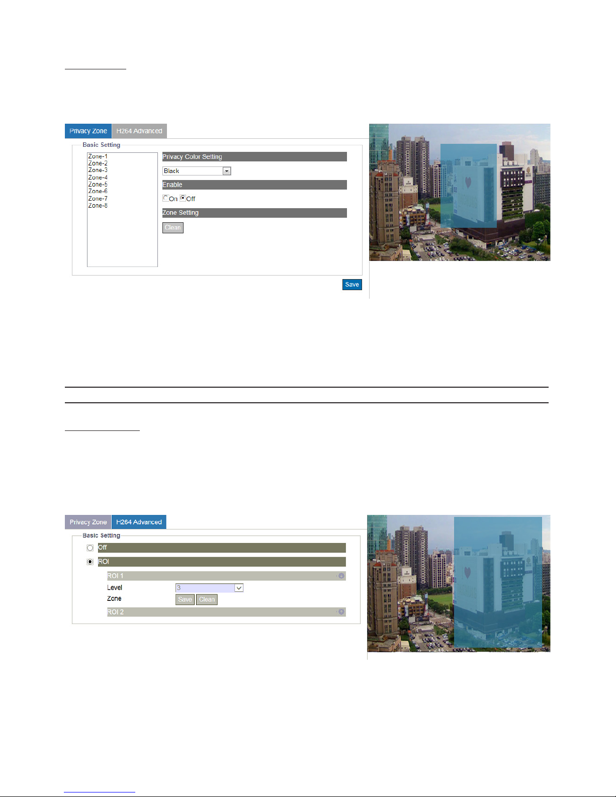
Privacy Zone
Privacy Zone enables user to black out a specic portion of the screen for privacy concern. There are up to 8 sets of privacy
zones for users to dene. After setting up a privacy zone, the live view image will appear a frame, whose color, size and
position can be customized by user’s preference.
Figure 4 - 10: Privacy Zone Setting
To set up a privacy zone, user needs rst to turn ON any of the eight privacy zones (multiple available) and adjust the privacy
mask size by pressing with left click and dragging to outline a desired privacy frame. Also, user can select a desired color (Black,
Grey or White) for privacy zone. Press “Save” to make settings take eect. If you intend to delete settings, click “Clean” to wipe
out privacy zone settings.
Note Please set the privacy zone slightly larger than the actual area to ensure privacy concern.
H264 Advanced
●ROI
ROI (Region Of Interest) is a feature that utilizes the intelligent algorithm to place diverse compression levels upon dierent
areas while retaining the target bitrate. By enabling, user can designate a customized zone, which will be compressed less,
to enhance the crystal image quality within the zone, while the undened zone, given less important, will be sacriced for
image quality by higher compression ratio.
Figure 4 - 11: ROI Settings
First, turn one of the ROI or both on and click and drag left button on the right-side preview image to outline a desired zone.
Also, user can select a wanted level for each ROI. Press “Save” to make settings take eect. If you want to delete settings, click
“Clean” to wipe out the selected Zone settings.
Page 28
27
4.2.4 Network
General
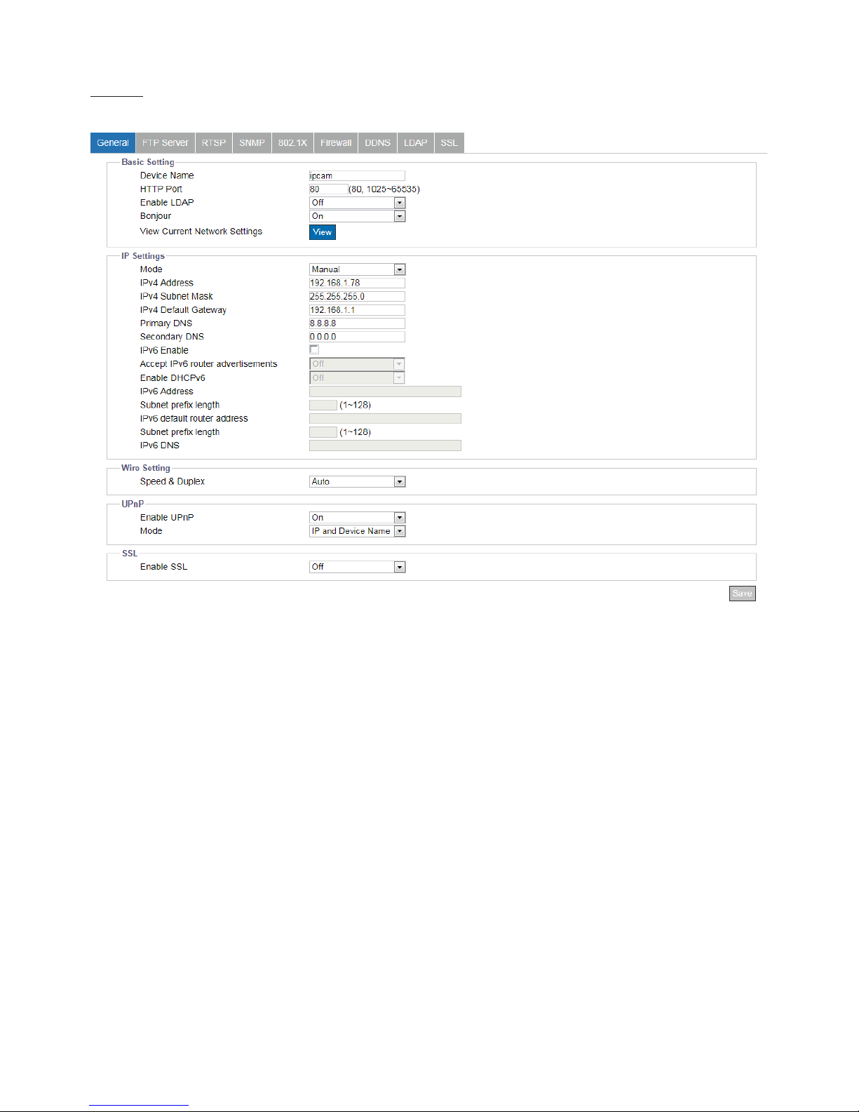
This section is for users to set detailed settings related to wired network condition for the camera.
Figure 4 - 12: Network
●Basic Settings
• Device Name: Input your preferred name for the camera..
• HTTP Port: This protocol allows for TCP protocol quality without having to open specic ports for streaming. Users inside
a rewall can utilize this protocol to allow streaming data through. It is recommended to use the default port number 80;
however, if it is required to change the port number, please contact your system administrator with options ranging from
1025 to 65535.
• Enable LDAP: For accessing and maintaining distributed directory information services over an Internet Protocol network,
the Lightweight Directory Access Protocol (LDAP), an open, vendor-neutral, industry standard application protocol, have a
major role in both intranet and internet applications to facilitate information sharing between devices.
• Bonjour: It’s a specic protocol introduced by Apple Inc. to make IP devices including IP cameras easily found by software
like Safari within local network on the basis of zero conguration.
• View Current Network Settings: Click “View” to see your current network related settings.
●IP Settings
• Mode
» Manual: User can manually input IP address and the related settings.
» PPPoE: This is a point-to-point based protocol which offers authentication, encryption and compression. It
predominantly authenticates user with the predened username and password.
» DHCP: If enabled, the camera will automatically obtain an available dynamic IP address from the DHCP server
each time it connects to the LAN.
• IPv4 Address: To manually set an IP address under IPv4.
• IPv4 Subnet Mask: Please use default address: 255.255.255.0. If subnet mask is not properly congured, the unit may not be
able to communicate with other devices.
Page 29
28
• IPv4 Default Gateway: Leave blank as default setting. No Default Gateway address required if not used. Ask your network
administrator for further information.
• Primary DNS: Same as the above.
• Secondary DNS: Same as the above.
• IPv6 Enable: Check the box to enable IPv6 protocol.
• Accept IPv6 router advertisements: Check the box to activate RA (Router Advertisement) corresponding to RS (Router
Solicitation) for IPv6 address designation.
• Enable DHCPv6: If enabled, the camera will automatically obtain an available dynamic IP address under IPv6 protocol from
the DHCP server each time it connects to the LAN.
• IPv6 Address: To manually set an IP address under IPv6 protocol.
• Subnet prex length: Set prex length for subnet ranging from 1 – 128.
• IPv6 default router address: To manually set a default router address under IPv6 protocol.
• Subnet prex length: Set prex length for subnet ranging from 1 – 128.
• IPv6 DNS: Set a DNS (Domain Name Server) under IPv6 protocol.
●Wire Setting
• Speed & Duplex: Due to the attribute of collision, Half Duplex can only send or receive information at one time, while Full
Duplex is able to receive and transmit in full line rate simultaneously without the issue of collision. For the number to Mbps,
larger the number, faster it results in; smaller the number, on the other hand, slower it brings about. “Auto” simply lets the
camera to decide which mode to adopt.
» 10Mbps Half Duplex:
» 10Mbps Full Duplex:
» 100Mbps Half Duplex:
» 100Mbps Full Duplex:
» Auto:
●UPnP
• Enable UPnP: When UPnP (Universal Plug & Play) is set to “ON”, the unit can be detected automatically by any computer in
the LAN to skip the installation of the IP Finder utility.
• Mode: When the camera connects with the LAN, select one of the modes below for identication:
» IP and Device Name: The device name and IP address will be shown synchronously.
» Device Name: Only device name will be shown.
» User Input: User can input a friendly customized name for the camera.
●SSL
• Enable SSL: Turn Secure Sockets Layer (SSL) ON to enable communication security mechanism over internet network.
Note Please click “Save” button to save your settings.
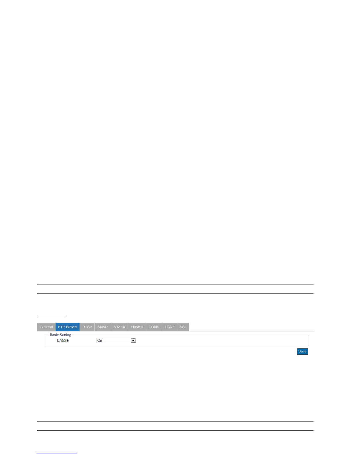
FTP Server
Figure 4 - 13: FTP Settings
●Enable
Simply click “ON” to activate the FTP server function or “OFF” to disable it.
To log on the FTP, simply enter ftp://<Login ID>:<Password>@<ip address> in the location field of Microsoft’s Internet
Explorer and the recordings will be shown up. The default setting, for example, is ftp://admin:[email protected]. The
maximum connection for FTP server is up to 30.
Note Please click “Save” button to save your settings.
Page 30
29
RTSP
RTSP is a standard protocol for connecting a client to establish and control streaming data over the web. If you want to allow
third-party devices or software to access video/audio streams from the IP camera over the network, you must congure the
RTSP ports. The major dierence between Unicast and Multicast is the way how client and server communicate packets with
each other. Specically, unicast transmits packets under 1 to 1 device method and multicast, on the other hand, transmits
via the way of 1 to multiple devices. Hence, unicast requires large network bandwidth and occupies more resources of server
but is more stable because of its simple structure; by contrast, multicast needs less bandwidth with resources and is more
practical for multiple devices broadcast on condition that all relevant peripheral devices like switch or router support the
multicast protocol. Please adopt proper method based on your network applications for better eciency.
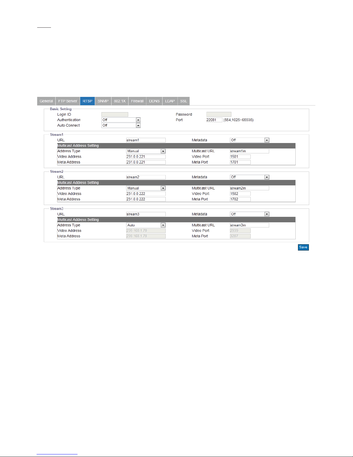
Figure 4 - 14: RTSP Settings
●Basic Settings & Authentication
Enabling the authentication will improve the verifying mechanism and thus make the RTSP connection process more
secured and much safer. To enable it, simply enter the Login ID, Password and Port (554 by default) with selecting “ON” in
Authentication. Turning “ON” for Auto Connect will enable auto connection. Please note that it is not required to enable
authentication beforehand to proceed with RTSP.
●URL
Input a preferred name for representing each RTSP Stream URL. Basically it refers to Unicast URL protocol which
transmitting data via one host to a single host, consuming more network bandwidth but with a direct and simple
transmission method. After dene preferred URL name for each stream, you can, via 3rd party software, enter the address
like the following examples for RTSP URL streaming.
• rtsp://(camera IP address)/(URL stream 1)
• rtsp://(camera IP address)/(URL stream 2)
• rtsp://(camera IP address)/(URL stream 3)
For example: rtsp://192.168.1.30/URL stream1
●Metadata
Turn Metadata ON to enable data about data, which means the data information will be allocated systematically, allowing
similar data together by certain criteria and also distinguishing dissimilar data organizationally to eectively transmitting
date information.
Page 31
30
●Multicast URL
Diering from URL, Multicast URL can transmit data from one host to a single host or to all hosts, thus consuming less
network bandwidth with more exibility. However, it is required to make sure if the peripherals connected with the
camera are all compatible with Multicast in advance. The address for Multicast is roughly same with the previous URL.
Please refer to the samples below:
• rtsp://(camera IP address)/(Multicast URL stream 1)
• rtsp://(camera IP address)/(Multicast URL stream 2)
• rtsp://(camera IP address)/(Multicast URL stream 3)
For example: rtsp://192.168.1.30/Multicast URL stream1
●Address Type
By selecting “Manual”, user can advance to the further Video and Meta settings below, while “Auto” simply keeps the
original settings by the camera
• Video & Meta Address/Port
Complex in its transmitting procedure and layer structure, Multicast streaming requires more specific settings
containing Video Address/Port and Meta Address/Port, both of which, as the UI suggesting, have a certain IP address
range (224.0.1.1 – 239.255.255.254) for user to dene individually.
Note Please click “Save” button to save your settings.
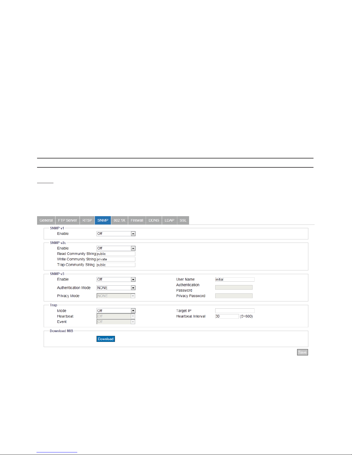
SNMP
SNMP (Simple Network Management Protocol) is an Internet standard protocol on top of application layer that restructures
the exchange of management information among network-attached nodes, which helps administrators to remotely manage
network devices and master network problems with ease.
Figure 4 - 15: SNMP Settings
●SNMP V1
Tick “ON” or “OFF” to enable or disable.
●SNMP V2
Tick “ON” or “OFF” to enable or disable.
• Read Community String: Input a string name for Read Community String
• Write Community String: Input a string name for Write Community String
• Trap Community String: Input a string name for Trap Community String
Page 32
31
●SNMP V3
SNMP V3 provides more security features than SNMP v1/SNMP v2. Tick “ON” to enable the function. Input User Name
for SNMP v3 rst. Then select desired modes for “Authentication” with “Privacy” and enter passwords paired with both
protocols individually.
●Trap
Trap under SNMP allows an agent to notify the management station of signicant events by way of an unsolicited SNMP
message, the asynchronous notication. Select which SNMP mode (v1, v2 or v3) to be enabled with Trap and input Target
IP for Trap Host.
●Heartbeat
To ensure a network free from delayed message, Heartbeat, this communications protocol sends back a message in a
given interval to properly conrm message is alive and in fact with a periodic heartbeat. Tick “ON” or “OFF” to enable or
disable heartbeat function here. Input Target IP & Interval of Heartbeat.
●Event
Specically designed for event occurrence, this option will, when turned ON, automatically record the log le of events
occurred for review afterwards.
● Download MIB
Click “Download” to get specics of MIB (Management Information Base). MIBs describe the structure of the management
data of a device subsystem; which uses a hierarchical namespace containing object identiers (OID). Each OID identies a
variable that can be read or set via SNMP.
Note Please click “Save” button to save your settings.
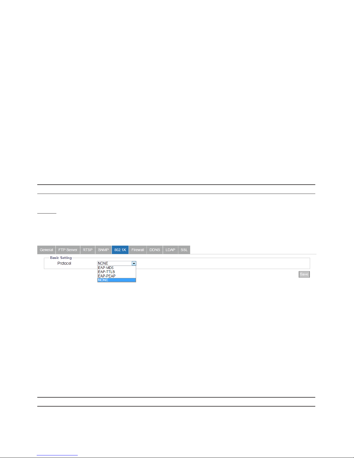
802.1X
802.1X is an IEEE Standard for Port-based Network Access Control and denes the encapsulation of the Extensible
Authentication Protocol (EAP) over IEEE 802 which is known as EAP over LAN. Simply click “ON” to activate it and further
select its related EAP protocol types.
Figure 4 - 16: 802.1X Settings
●NONE
None of the protocols is selected by user.
●EAP-MD5
It is the only IETF Standards Track based EAP method and oers the minimal security.
●EAP-TTLS
Tunneled Transport Layer Security (TTLS) is an EAP protocol and is well-supported among wireless vendors. It further
extends TLS protocol and is widely supported across a variety of platforms.
●EAP-PEAP
The Protected Extensible Authentication Protocol (PEAP) was jointly developed by Cisco Systems, Microsoft, and RSA
Security and provides unique security for users.
Note Please click “Save” button to make your settings take eect.
Page 33
32
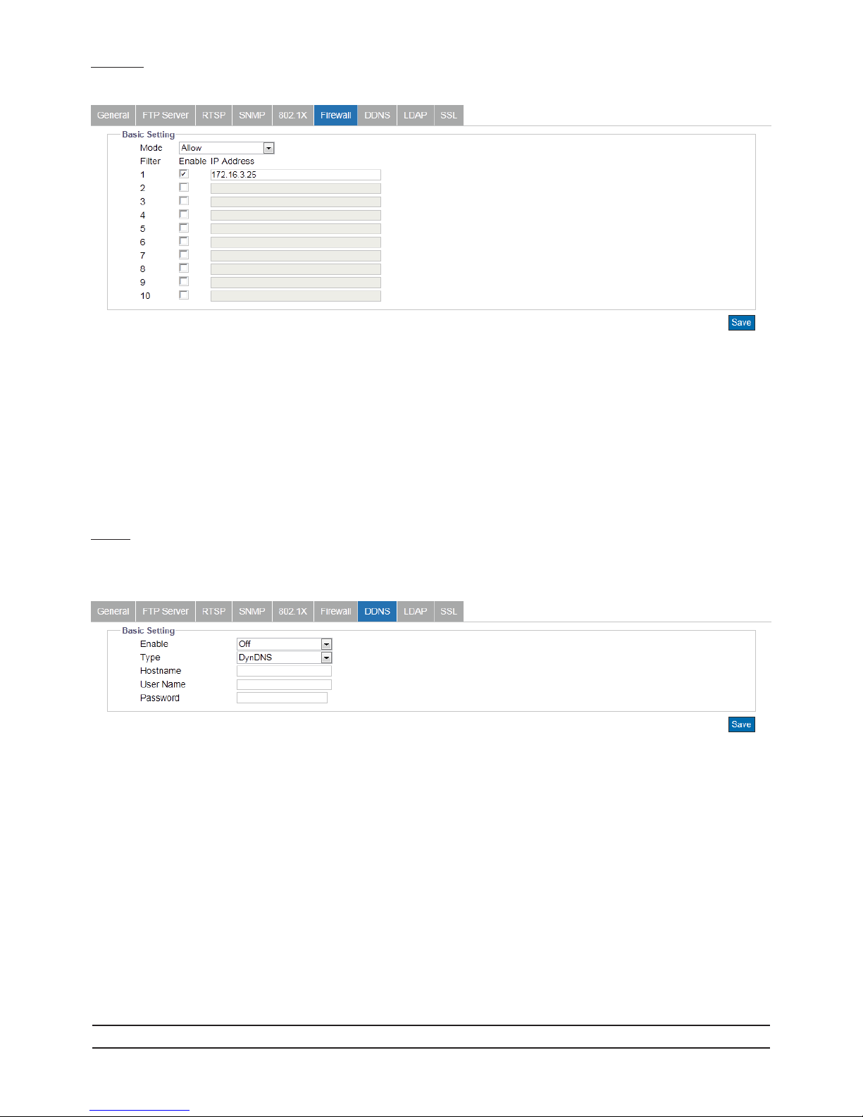
Firewall
Under this menu, users can manually dene several IP addresses to be allowed or denied to access camera.
Figure 4 - 17: Firewall Settings
●Allow: Select this option to make inputted IP addresses allowed to access IP camera.
●Deny: Select this option to make inputted IP addresses denied to access IP camera.
●OFF: By selecting this option, none of actions will be made for inputted IP addresses.
●IP Address (1-10): Manually input IP addresses in each of the elds to be allowed or denied access. After inputting address,
check the box in front of each inputted address to activate the lters of allow or deny.
DDNS
Dynamic Domain Name Server (DDNS) is the system which can automatically update DSN records without further manual
editing in a real time manner, therefore resulting in web address directing faster and smoother.
Figure 4 - 18: DDNS Settings
●Basic Settings
• Enable: Select “ON” to enable DDNS function.
• Type: There are 4 types of DDNS for selection as the following items.
» DynDNS: One of the DDNS providers oering service with fee collection.
» No-IP: A DDNS provider oering free service. Please register yourself before enabling this type.
» Two-DNS: A DDNS provider oering free service. Please register yourself before enabling this type.
» FreeDNS: A DDNS provider oering free service. Please register yourself before enabling this type.
• Hostname: Dene a specic hostname for DDNS.
• User Name: Congure a privileged username for accessing to DDNS.
• Password: Input the password associated with the privileged username.
• Hash: It is required to set up the value when selecting FreeDNS type.
Note Please click “Save” button to save your settings.
Page 34
33
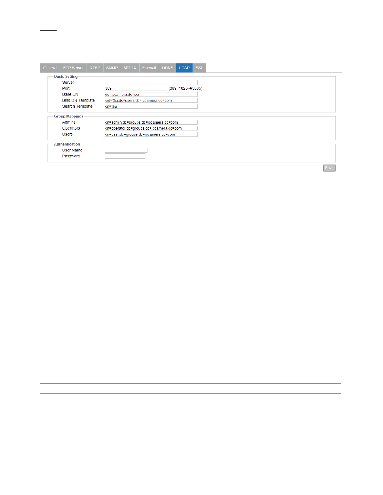
LDAP
For accessing and maintaining distributed directory information services over an Internet Protocol network, the Lightweight
Directory Access Protocol (LDAP), an open, vendor-neutral, industry standard application protocol, have a major role in both
intranet and internet applications to facilitate information sharing between devices.
Figure 4 - 19: LDAP Settings
●Basic Settings
• Server: Input a server for LDAP.
• Port: It is recommended to use the default port number 389; however, if it is required to change the port number, please
contact your system administrator with options ranging from 1025 to 65535.
• Base DN: The string within the eld of Base DN (Distinguish Name) is altered by the LDAP server to be accessed. Refer to the
eld here for manipulation later.
• Bind DN Template: The string within the eld of Bind DN (Distinguish Name), which is the sub level under Base DN, is altered
by the LDAP server to be accessed. Refer to the eld here for manipulation later.
• Search Template: The string within the eld of Search Template is altered by the LDAP server to be accessed. Refer to the eld
here for manipulation later.
●Group Mappings
• Admins: The string within the field of Admins, which relates to the LDAP admin privileges that can operate with full
functions, is altered by the LDAP server to be accessed. Refer to the eld here for manipulation later.
• Operators: The string within the field of Operators, which relates to the LDAP operator privileges that can operate with
live view, snapshot, record file and full screen, is altered by the LDAP server to be accessed. Refer to the field here for
manipulation later.
• Users: The string within the eld of Users, which relates to the LDAP user privileges that can merely watch live view, is altered
by the LDAP server to be accessed. Refer to the eld here for manipulation later.
●Authentication
• User Name: Enter a designated username for authentication to the accessed LDAP.
• Password: Enter the password corresponding to the inputted username for correct authentication.
Note Please click “Save” button to save your settings.
Page 35

34
SSL
Secure Sockets Layer (SSL), the standard security technology for establishing encryption, allows sensitive information such as
login credentials to be transmitted securely.
Figure 4 - 20: SSL Settings
●Self Signed
Self-signed certicate is a private own key that has no connection with person or organization that perform authorized
certificate signing procedure. Select it and input the required fields below to display information of a self-signed
certicate.
Figure 4 - 21: Self Signed & Request Settings
●Request
Roughly similar to the settings of Self-Signed, by clicking the “Generate Certicate” after inputting the required elds,
Request will provide user, apart from showing the information like self signed, with a download option of created
certicate for future utilization.
●Upload Certicate
After downloading the certicate from Request page, user can upload it to the camera via clicking “Browse” to locate
the created certicate for “Upload Certicate”. In addition, it is required to browse and upload the other CA (Certicate
Authority), which is issued by authorized person or organization, followed by clicking the “Upload” to complete the SSL
procedure.
Figure 4 - 22: Upload Certicate
Page 36
35
4.2.5 System
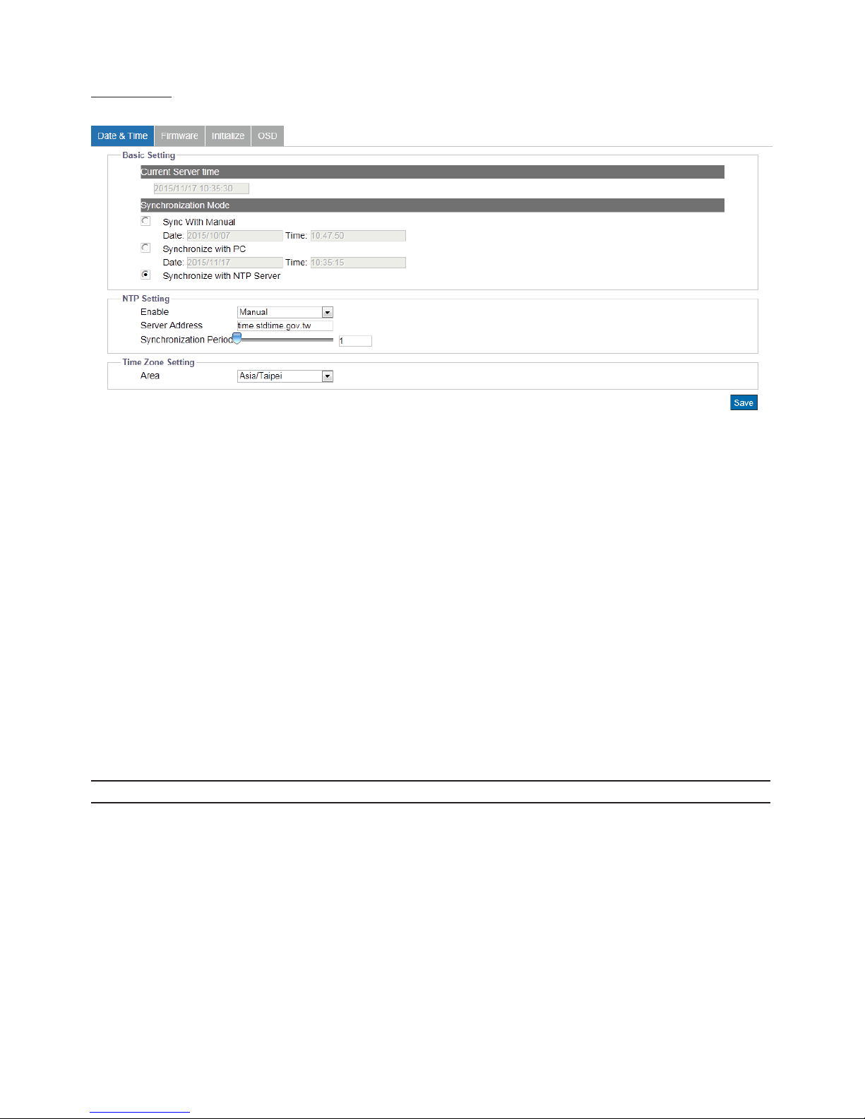
Date & Time
Figure 4 - 23: Date & Time Settings
●Current Server Time
The current date/time is displayed here.
●Synchronization Mode
There’re 3 modes for users to set date/time.
• Sync With Manual: Manually set date and time individually.
• Synchronize with PC: Select it to synchronize date/time consistent with connected computer.
• Synchronize with NTP Server: Select it to synchronize date/time with the assigned NTP server.
●NTP Settings
• Enable: Enable NTP by “Manual”, which allows user to input desired NTP server address, or “From DHCP Server”, which obtains
a NTP address assigned by DHCP Server.
• Server Address: Input desired NTP server address in the eld.
• Synchronization Period: Select sync period ranging from 1 to 24.
●Time Zone Setting
• Area: Choose one of the time zones based on your located country/area.
Note Please click “Save” button to save your settings.
Page 37
36
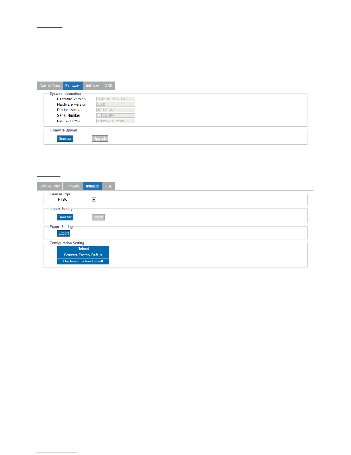
Firmware
The information about the camera are explicitly written under this page. Also, users can manually update System Firmware if
available. All motions of camera will be stopped during the rmware update. Please close any other screens before rmware
update. Never disconnect power or LAN cable during the updating process. It takes approximately 3 minutes for the unit
to reboot after rmware update process. Again, power can’t be lost when updating rmware since it will cause the update
failure and manufacturer maintenance will be therefore required. Click “Browse” to locate a corresponding rmware le and
click “Upgrade” to proceed.
Figure 4 - 24: Firmware Settings
Initialize
Figure 4 - 25: Initialize Settings
●Camera Type
Select “NTSC” or “PAL” in accordance with different requirements. Flickering by fluorescent light can be reduced by
selecting “PAL” for the power frequency 50Hz or “NTSC” for the power frequency 60Hz
● Import Setting
Press “Browse” to locate a le and then click “Import” to upload conguration settings from local to the camera.
●Export Setting
Press “Export” to download conguration settings to local computer.
●Reboot
Press “Reboot” to simply reboot the camera.
●Software Factory Default
Press it to reset all conguration settings back to factory defaults excluding network settings.
●Hardware Factory Default
Press it to reset all conguration settings back to factory defaults.
Page 38
37
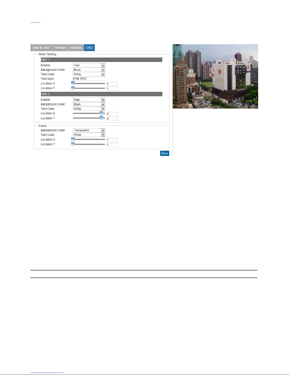
OSD
This section allows user to enable OSD (On Screen Display) settings. In addition, it extends the OSD function to accord with
the occurrence of events.
Figure 4 - 26: OSD Settings
●Basic Settings
There are up to 2 sets of OSD settings can be enabled concurrently as the following details:
• Enable: Select to display “Date” or “Text” on the screen.
• Background Color: Choose a background color (“Transparent” or “Black”) for OSD
• Text Color: Choose text color (“White” or “Black”) for OSD.
• Text Input: Input a wanted text to display on the live view screen.
• Location X: Input a value to decide the exactly horizontal position for OSD.
• Location Y: Input a value to decide the exactly vertical position for OSD.
●Event
When an event is triggered, OSD can be displayed on screen to highlight and inform user.
• Background Color: Choose a background color (“Transparent” or “Black”) for event OSD.
• Text Color: Choose text color (“White” or “Black”) for event OSD.
• Location X: Input a value to decide the exactly horizontal position for event OSD.
• Location Y: Input a value to decide the exactly vertical position for event OSD.
Note Please click “Save” button to save your settings.
Page 39
38
4.2.6 Account
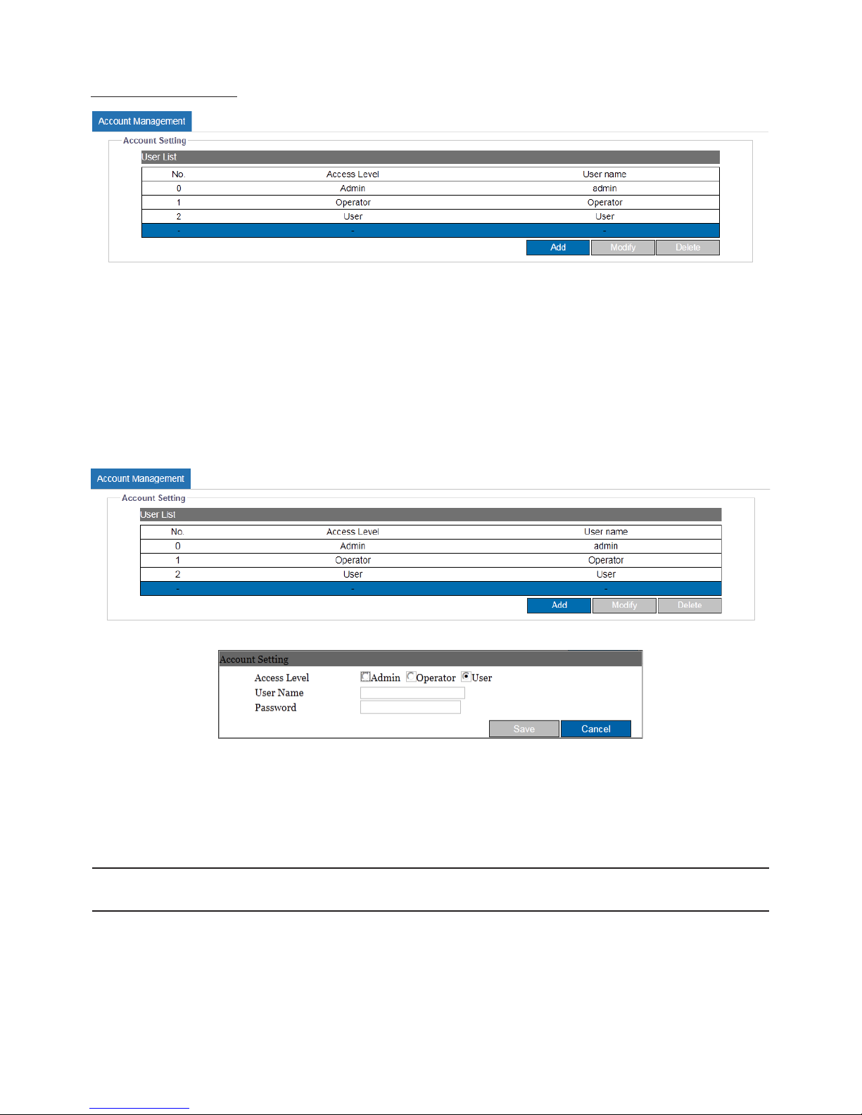
Account Management
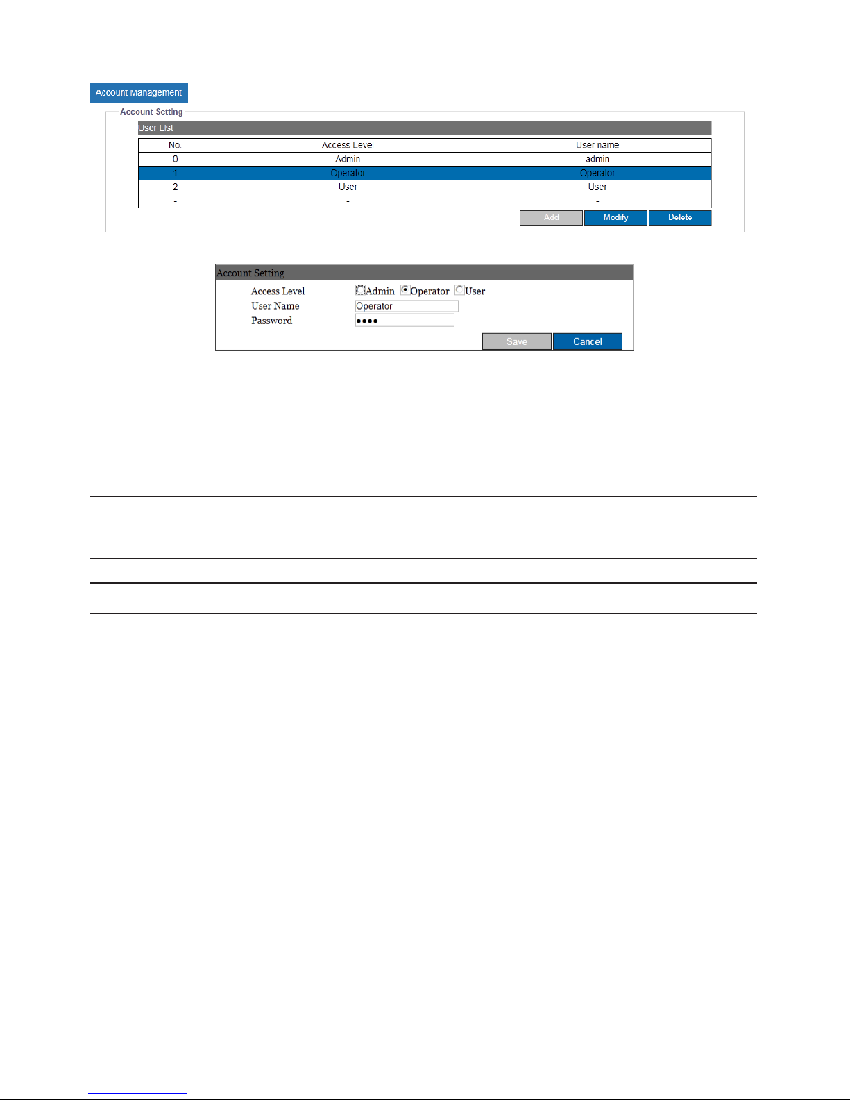
Figure 4 - 27: Account Settings
●User Levels
• Admin: The highest privileged control for the camera is “Admin” level, which can handle both live view and all the
conguration settings. The default username and password for Admin are “admin” and “1234” respectively.
• Operator: Diering from Admin, Operator level can access to camera for live view, storage, and remote lens control functions
merely.
• User: Being the lowest level, User level can only access to camera for live view function.
●Add Users:
Figure 4 - 28: Add Admin/Operator/User
• Add: Place the mouse cursor over the blank column and click the “Add” button. The prompt window will pop up for you to
input customized username and password for new user, the level (Admin, Operator or User) of which is also available to be
selected here.
Note
• Up to 10 users are available to coexist.
• Please click “Save” button to save your settings. Click “Cancel” will exit and discard saving.
Page 40
39
●Modify & Delete Users:
Figure 4 - 29: Modify & Delete Admin/Operator/User
• Delete: Choose one of the users from the list and then click “Delete” to remove it instantaneously. (The default Admin is not
available to be deleted.)
• Modify: Choose one of the users from the list rst, and enter updated information if necessary. Finally click “Save” to take
eect.
Note
• At least 4 texts are required to form a username.
• The login Username and Password are supported within 16 characters with the valid alphanumeric value
merely including '0' to '9', 'a' to 'z', 'A' to 'Z', '.','-','+','_'and '@'.
Note Please click “Save” button to save your settings. Click “Cancel” will exit and discard saving.
Page 41
40
4.2.7 Event Source
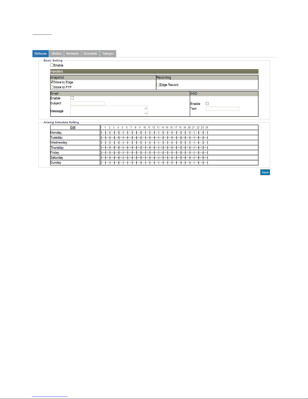
Defocus
This function is designed to establish related actions when the camera is subject to the event of defocus.
Figure 4 - 30: Defocus Settings
●Basic Setting
• Enable: Check the box to enable the function.
●Handlers
• Snapshot
» Store to Edge: This relates to snapshot capture when defocus happens. Check the box to save the snapshot of
defocus event to the inserted SD card.
» Store to FTP: This relates to snapshot capture when defocus happens. Check the box to save the snapshot of
defocus event to the FTP site, which should be properly set up in advance.
• Recording
» Edge Record: This relates to video recording when defocus happens. Check the box to save the recorded video
of defocus event to the inserted SD card.
• Email
» Enable: Check the box to enable the function of Email sending when defocus occurs.
» Subject: To preset a subject of the email to be sent.
» Message: To preset message contents of the email to be sent.
• OSD
» Enable: Check the box to enable the OSD function when defocus occurs.
» Text: Manually input desired text to display when defocus occurs.
Page 42
41
●Arming Schedule Setting
Under this section, user can freely set up an ideal combination to record defocus events. The following table includes 7 days a
week from the upper Monday to the lower Sunday with the hour group from the left 00 to the right 24. Click the “Edit” button
at the upper-left corner to enter the setting page.
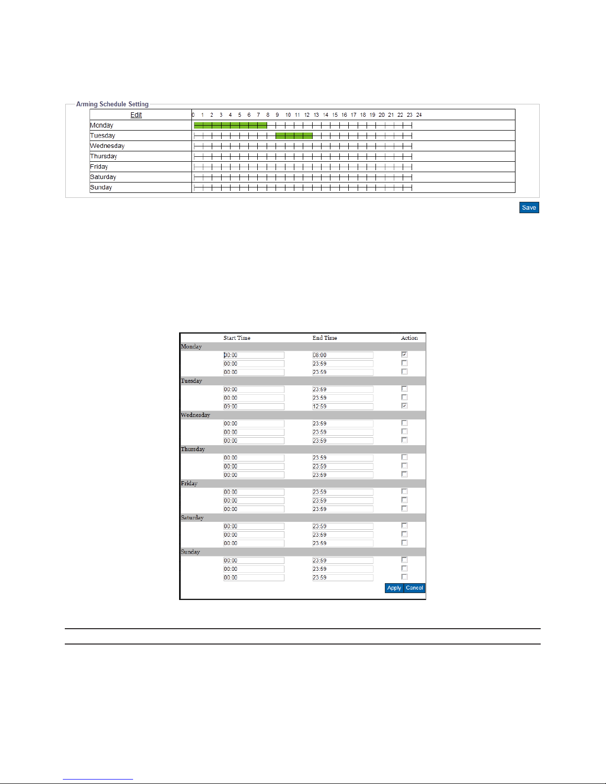
Figure 4 - 31: Arming Schedule Setting for Defocus
After clicking “Edit”, the prompt setting page will be shown as follows. User is able to individually establish up to 3 sets of time
range for each day, where start and end time can be separately dened. Check the box at the right side to concretely enable
the dened time range followed by clicking “Apply” to take eect. Take the screenshot below for example, we can clearly see
that the 2 time ranges, Monday (00:00 – 08:00) and Tuesday (09:00 – 12:59), are properly dened and checked. And the above
screenshot further shows that the dened time ranges are highlighted with bright green color to indicate any defocus event
within the green time ranges will be recorded properly.
Figure 4 - 32: Arming Schedule Setting Page
Note Please click “Save” button to save your settings.
Page 43
42
Motion
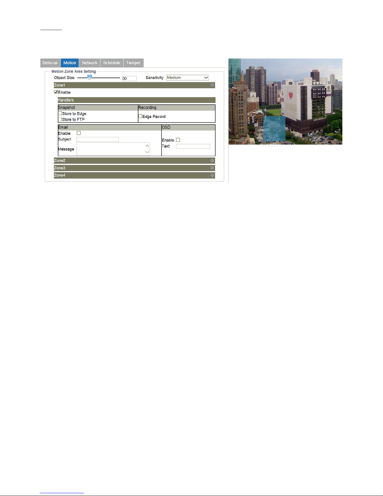
This function is designed to establish related actions when the camera detects motion issues. A maximum of 4 sets of motion
detection areas can be customized by users.
Figure 4 - 33: Motion Detection Settings
●Motion Zone Area Setting
• Object Size: Dene a value ranging from 1 – 100 for object size to be detected. Lower the value, smaller the object can be
detected, and vice versa.
• Sensitivity: Set the sensitivity for motion detection. High stands for that camera is prone to be triggered with slight motion
or light change within the live view, while Low means that camera is triggered with only major change in motion or light.
• Enable: Draw a desired size with position on the right-side preview image for motion detection followed by checking the
box and clicking “Save Area” to have the settings take eect.
●Handlers
• Snapshot
» Store to Edge: This relates to snapshot capture when motion event happens. Check the box to save the snapshot
of motion event to the inserted SD card.
» Store to FTP: This relates to snapshot capture when motion event happens. Check the box to save the snapshot
of motion event to the FTP site, which should be properly set up in advance.
• Recording
» Edge Record: This relates to video recording when motion event happens. Check the box to save the recorded
video of motion event to the inserted SD card.
• Email
» Enable: Check the box to enable the function of Email sending when motion event occurs.
» Subject: To preset a subject of the email to be sent.
» Message: To preset message contents of the email to be sent.
• OSD
» Enable: Check the box to enable the OSD function when motion event occurs.
» Text: Manually input desired text to display when motion event occurs.
Page 44
43
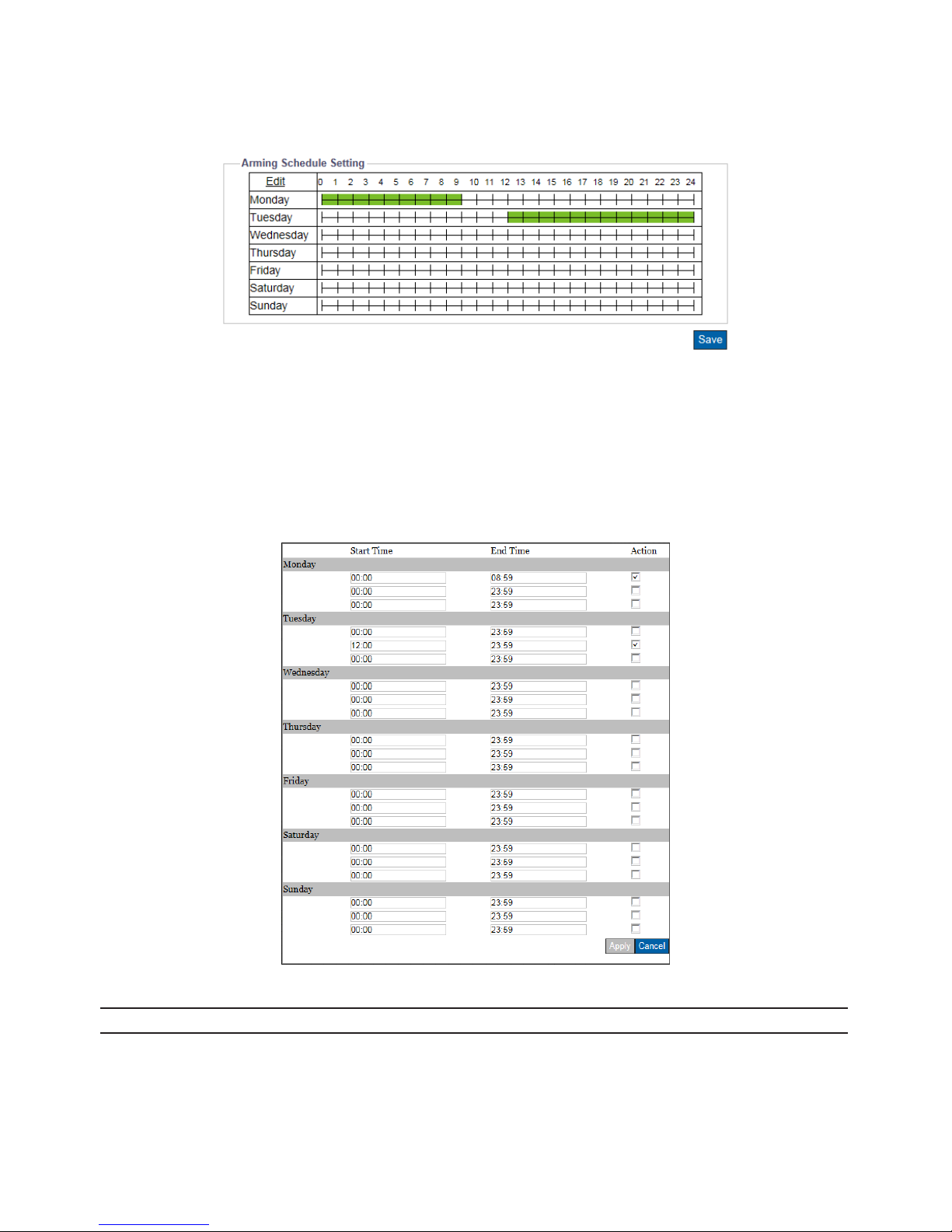
●Arming Schedule Setting
Under this section, user can freely set up an ideal combination to record motion events. The following table includes 7 days a
week from the upper Monday to the lower Sunday with the hour group from the left 00 to the right 24. Click the “Edit” button
at the upper-left corner to enter the setting page.
Figure 4 - 34: Arming Schedule Setting for Motion
After clicking “Edit”, the prompt setting page will be shown as follows. User is able to individually establish up to 3 sets of time
range for each day, where start and end time can be separately dened. Check the box at the right side to concretely enable
the dened time range followed by clicking “Apply” to take eect. Take the screenshot below for example, we can clearly see
that the 2 time ranges, Monday (00:00 – 08:59) and Tuesday (12:00 – 23:59), are properly dened and checked. And the above
screenshot further shows that the dened time ranges are highlighted with bright green color to indicate any motion event
within the green time ranges will be recorded properly.
Figure 4 - 35: Arming Schedule Setting Page
Note Please click “Save” button to save your settings.
Page 45
44
Network
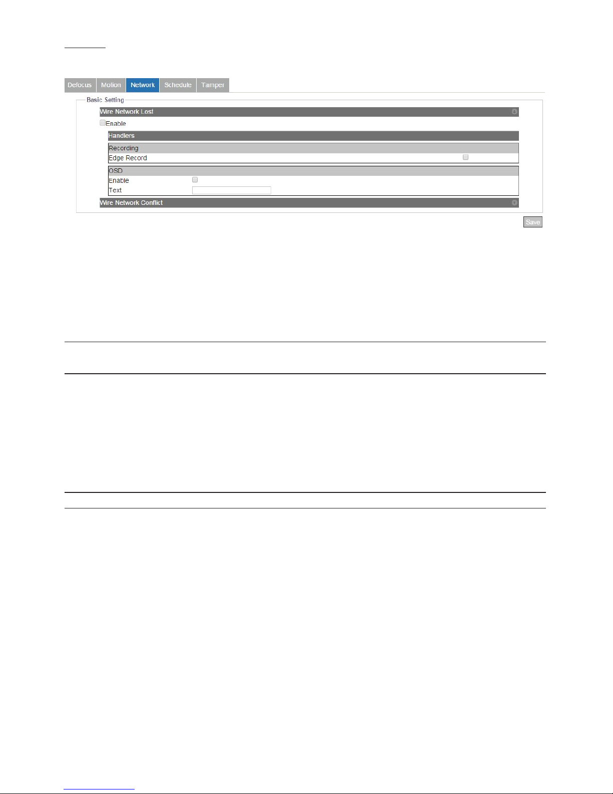
This function is designed to establish related actions when the camera is subject to network conict or network lost events.
Figure 4 - 36: Network Event Settings
●Wire Network Issues
• Network Lost: Check the box to enable the detection of network lost. When the camera loses internet access, the network
lost event will be detected and recorded.
• Network Conict: Check the box to enable the detection of network conict. When there is another IP address conicts with
the camera, the network conict event will be detected and recorded.
Note
Press the arrow buttons at the upper-right corner to expand or collapse the setting pages of Network Lost
and Network Conict.
●Handlers
• Recording
» Edge Record: This relates to video recording when network conict or network lost happens. Check the box to
save the recorded video of network events to the inserted SD card.
• OSD
» Enable: Check the box to enable the OSD function when network events occur.
» Text: Manually input desired text to display when network event occurs.
Note Please click “Save” button to save your settings.
Page 46
45
Schedule
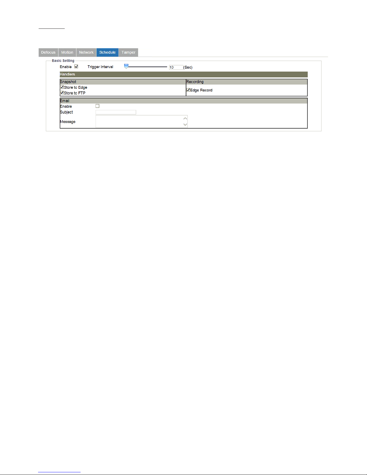
This function is designed to establish related actions for schedule recording.
Figure 4 - 37: Schedule Recoding Settings
●Basic Setting
• Enable: Check the box to enable schedule recording function.
• Trigger Interval: This relates to the following handler actions. The available range is from 1 to 3600 seconds. For example, if
enabling the “Snapshot – Store to FTP” and setting the interval value as “3600”, the camera will regularly save snapshot from
schedule recording to the designated FTP site.
●Handlers
• Snapshot
» Store to Edge: This relates to snapshot capture for schedule recording. Check the box to save the snapshot of
schedule recording to the inserted SD card.
» Store to FTP: This relates to snapshot capture for schedule recording. Check the box to save the snapshot of
schedule recording to the FTP site, which should be properly set up in advance.
• Recording
» Edge Record: This relates to video recording for schedule recording. Check the box to save the recorded video of
schedule recording to the inserted SD card.
• Email
» Enable: Check the box to enable the function of Email sending for schedule recording.
» Subject: To preset a subject of the email to be sent.
» Message: To preset message contents of the email to be sent.
Page 47
46
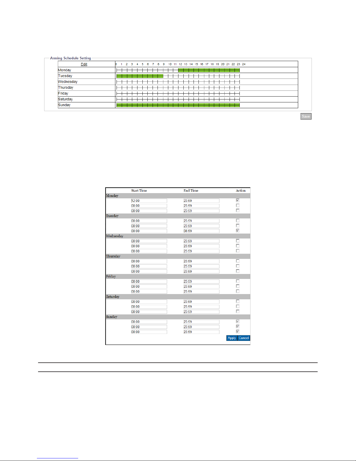
●Arming Schedule Setting
Under this section, user can freely set up an ideal combination for schedule recording. The following table includes 7 days a
week from the upper Monday to the lower Sunday with the hour group from the left 00 to the right 24. Click the “Edit” button
at the upper-left corner to enter the setting page.
Figure 4 - 38: Arming Schedule Setting for Schedule
After clicking “Edit”, the prompt setting page will be shown as follows. User is able to individually establish up to 3 sets of time
range for each day, where start and end time can be separately dened. Check the box at the right side to concretely enable
the dened time range followed by clicking “Apply” to take eect. Take the screenshot below for example, we can clearly see
that the3 time ranges, Monday (12:00 – 23:59), Tuesday (00:00 – 08:00) and Sunday (00:00 - 23:59 ), are properly dened and
checked. And the above screenshot further shows that the dened time ranges are highlighted with bright green color to
indicate that camera will automatically record videos within the dened time ranges.
Figure 4 - 39: Arming Schedule Setting Page
Note Please click “Save” button to save your settings.
Page 48

47
Tamper
This function is designed to establish related actions when the camera is subject to tamper events.
Figure 4 - 40: Tamper Detection Settings
●Basic Setting
• Enable: Check the box to enable the tamper detection.
• Sensitivity: Set the sensitivity for tamper detection. High stands for that camera is prone to be triggered with slight tamper
issue, while Low means that camera is triggered with only major tamper issue.
●Handlers
• Snapshot
» Store to Edge: This relates to snapshot capture when tamper event happens. Check the box to save the snapshot
of tamper event to the inserted SD card.
» Store to FTP: This relates to snapshot capture when tamper event happens. Check the box to save the snapshot
of tamper event to the FTP site, which should be properly set up in advance.
• Recording
» Edge Record: This relates to video recording when tamper event happens. Check the box to save the recorded
video of tamper event to the inserted SD card.
• Email
» Enable: Check the box to enable the function of Email sending when tamper event occurs.
» Subject: To preset a subject of the email to be sent.
» Message: To preset message contents of the email to be sent.
• OSD
» Enable: Check the box to enable the OSD function when tamper event occurs.
» Text: Manually input desired text to display when tamper event occurs.
●Arming Schedule Setting
Under this section, user can freely set up an ideal combination to record tamper events. The following table includes 7 days a
week from the upper Monday to the lower Sunday with the hour group from the left 00 to the right 24. Click the “Edit” button
at the upper-left corner to enter the setting page.
Figure 4 - 41: Arming Schedule Setting for Tamper
Page 49
48
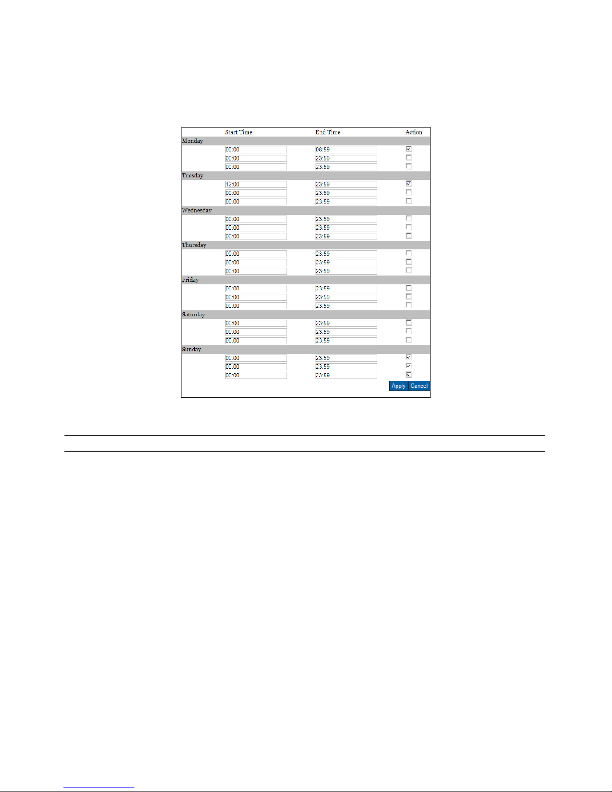
After clicking “Edit”, the prompt setting page will be shown as follows. User is able to individually establish up to 3 sets of time
range for each day, where start and end time can be separately dened. Check the box at the right side to concretely enable
the dened time range followed by clicking “Apply” to take eect. Take the screenshot below for example, we can clearly see
that the 2 time ranges, Monday (00:00 – 08:59) , Tuesday (12:00 – 23:59) and Sunday (00:00 - 23:59), are properly dened and
checked. And the above screenshot further shows that the dened time ranges are highlighted with bright green color to
indicate that any tamper event within the green time ranges will be recorded properly.
Figure 4 - 42: Arming Schedule Setting Page
Note Please click “Save” button to save your settings.
Page 50
49
4.2.8 Event Handler
Email
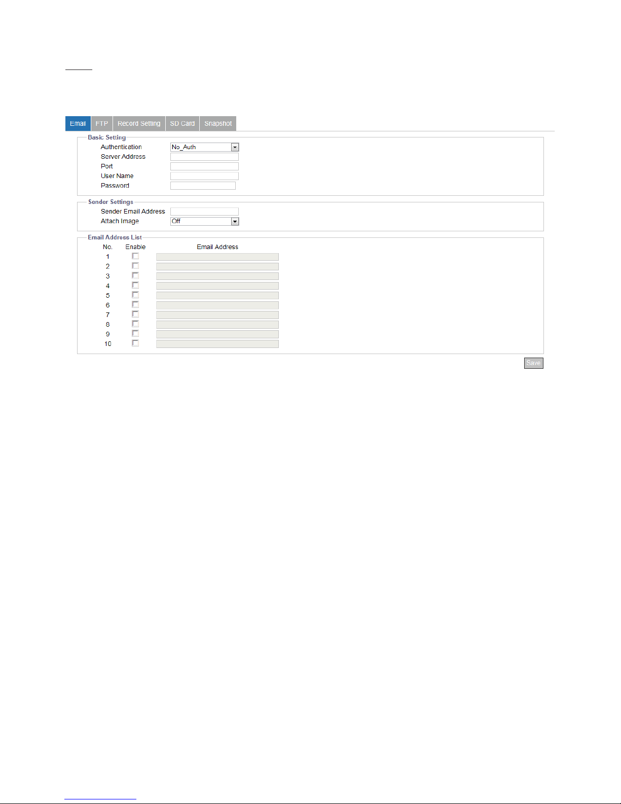
This section is designed to set up detailed settings for email notication when events occur. Make sure you have enabled
email sending function in each event section in advance.
Figure 4 - 43: Email Record Setting
●Basic Setting
• Authentication: Select an authentication type as following details:
» No_Auth: No restriction
» SMTP_Plain: PLAIN is the name of a registered SASL authentication mechanism which serves as a parameter to
the AUTH command. The PLAIN authentication mechanism is described in RFC 2595. Plain is the least secure of
all the SASL authentication mechanisms since the password is sent unencrypted across the network.
» Login: The Login mechanism is supported by Microsoft's Outlook Express and by some other clients.
» TLS_TTLS: TLS is usually implemented on top of any of the Transport Layer protocols encapsulating the
application-specic protocols such as HTTP, FTP, SMTP, NNTP and XMPP. The TLS protocol allows client-server
applications to communicate across a network in a way designed to prevent eavesdropping and tampering. TLS
can also be used to tunnel an entire network stack to create a VPN as is the case with OpenVPN.
• Server Address: Input a designated server address for email notication.
• Port: Set “25” as default or change to dedicated number. Ask technician for details if necessary.
• User Name: Input a username with privilege to access the server.
• Password: Input the password associated with the username.
●Sender Settings
• Sender Email Address: Dene the sender email address into the eld.
• Attach Image: Select “On” to enable attaching the detected image of events to the sending email.
Page 51
50
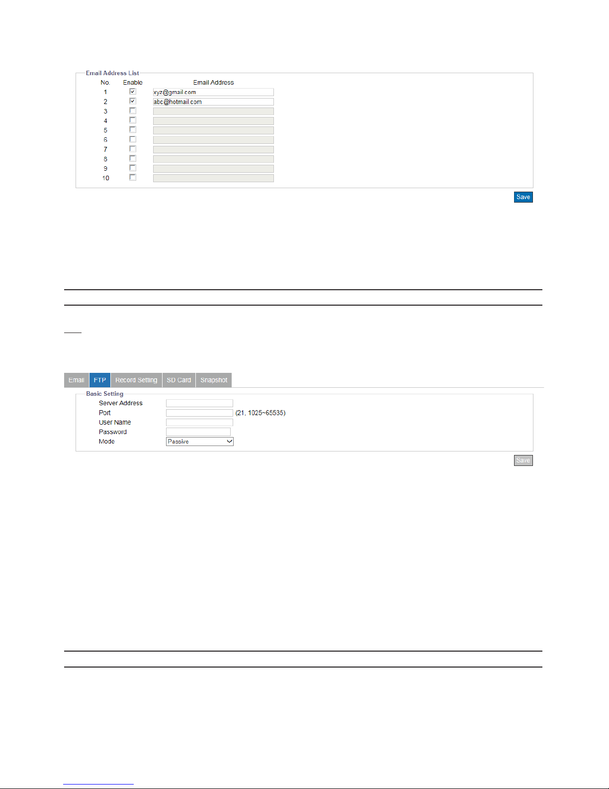
●E-mail Address List:
This function is designed to notify multiple users via email when events occur.
Figure 4 - 44: Email Address List
• Check “Enable” to send email to the selected address.
• Email Address: Input an email address to which events will be sent. There’re maximum 10 email addresses can be dened
here.
Note Please click “Save” button to save your settings.
FTP
This section is designed to set up detailed settings for FTP image storing when events occur. Make sure you have enabled FTP
function in each event section in advance.
Figure 4 - 45: FTP Settings
●Basic Setting
• Server Address: Input a FTP server address.
• Port: Set “21” as default or change to dedicated number. Ask technician for details if necessary.
• Username: Input a username with privilege to access the server.
• Password: Input the password associated with the username.
• Mode: Decide which connection mode to be utilized as the following details:
» Active: The camera will keep reconnecting with the designated FTP site when selecting “Active”, which occupies
more network bandwidth but with instant response to FTP.
» Passive: By selecting this option, the camera will only connect with the designated FTP site when necessary,
which largely help save the network bandwidth.
Note Please click “Save” button to save your settings.
Page 52
51
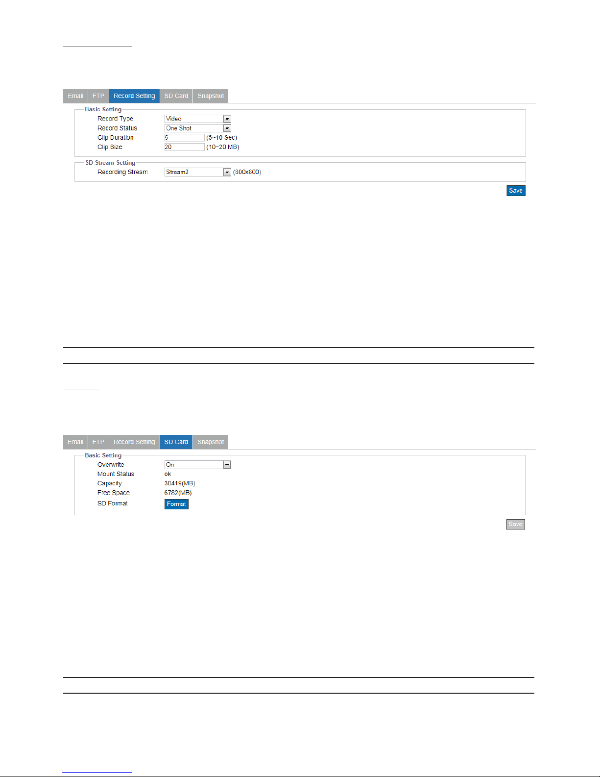
Record Setting
This section is designed to set up detailed settings for video recording. Make sure you have enabled recording function in
each event section in advance.
Figure 4 - 46: Record Setting
●Basic Setting
• Record Type: Select the recording content. Video: camera will only record the video information . Audio and Video: camera
will record both audio and video.
• Record Status: Dene the method of recording. One Shot: camera records with designated duration and le size.
Continuous: camera keeps recording continuously.
• Clip Duration: Set the length limit for recording le. The available range is from 5 to 10 seconds.
• Clip Size: Dene the le size for recording le ranging from 10 to 20MB.
Note Please click “Save” button to save your settings.
SD Card
This section is designed to set up detailed settings for Edge Recording when events occur. Make sure you have enabled Edge
Record function in each event section in advance.
Figure 4 - 47: SD Record Setting
●Basic Setting
•
Overwrite: It stands for that recorded files will be overwritten when SD card is in full capacity. Select ON to enable this
function.
•
Mount Status: It shows status about if the inserted SD card is well mounted.
•
Capacity: To show the capacity of the inserted SD card.
•
Free Space: To show the free space of the inserted SD card.
•
SD Format: Click “Format” to start formatting the mounted SD card right away.
Note Please click “Save” button to save your settings.
Page 53
52
Snapshot
This section is designed to set up detailed settings for snapshot capture when events occur. Make sure you have enabled
Snapshot function in each event section in advance.
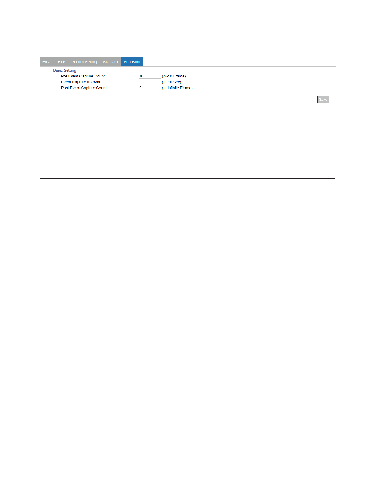
Figure 4 - 48: Snapshot Setting
●Basic Setting
• Pre Event Capture Count: Set a number of snapshots to be captured prior to an event.
• Event Capture Interval: Set a time interval ranging from 1 to 10 seconds between each snapshot capture.
• Post Event Capture Count: Set a number of snapshots to be captured after an event occurred.
Note Please click “Save” button to save your settings.
Page 54

53
Appendix: Specications of Mini Outdoor IR Dome Camera
Video
Sensor Type 1/2.8" image sensor optimized for low-light performance
Active Pixels 2065 x 1553 (HxV)
Compression H.264 / Motion JPEG
Streaming Triple simultaneous streams
Resolution 3MP(2048x1536), Full HD 1080P, 1.3MP(1280x960), HD 720P to 320x176
Max. Frame Rate 3MP(2048x1536) at 30 fps (NTSC) and 25 fps (PAL)
Day/Night Mechanical (ICR) D/N control
Day/Night Mode Auto
Shutter Time
Range from 1/10000s to 1/7.5s selectable (60Hz);
Range from 1/10000s to 1/6.25s selectable (50Hz)
Minimum Illumination 0.1 Lux @50IRE, 0.02 Lux @10IRE, F1.8
Video Output 1 x Mini USB to RJ45 interface for real-time preview
Bit Rate Control
Primary stream bit rate control: CBR/CVBR
Advanced quality of service (QoS)
Multi-level group of picture (Gop)
Region of interest (ROI)
Lens
Lens Type Built-in;xedfocal
Focal Length, F-number f=2.8mm, F1.8
View Angle H: 102° / V:85°
IR LEDs
LED Quantity 10 pcs (850nm)
IR Distance 25 meters (82 ft.)
IR turn on status Under 2 Lux by auto control
LED Life More than 10,000 hours (50ºC)
IR Control
IR Mode Auto / ON / OFF
IR Optimizer ON / OFF
IR Level Auto / Manual
Image Enhancement
Image Settings
AWB, AES, AGC
Exposure Mode: Auto/Flickerless/Shutter Priority/Manual
White Balance: ATW/Auto/Manual/One-Push;
Highlight Compensation: ON/OFF selectable;
Sharpness, Saturation, Brightness, Contrast: 200 level sensitivity
WDR Enhanced Digital WDR
DNR 3DNR
Defog Yes
Privacy Zone Yes, 8 zones selectable
Image Orientation Mirror, Flip
Frequency Control NTSC (60Hz), PAL (50Hz)
Date & Time Stamp Ye s
Intelligent Video & Event Management
Motion Detection Yes
Tamper Detection Yes
Network Loss Detection Yes
Loitering Detection Yes
Others Snapshot
Events Motion Detection, Loitering Detection, Network Loss Detection and Tamper Detection
Event Actions
Event snapshot by schedule and video analytics to
remote FTP storage
Event snapshot by video analytics to multiple email recipients
Recording to SD card
Page 55

54
Store Category
Event snapshot, SD recording, Manual Snapshot, Manual Recording, Routine schedule
recording
Local Storage*
Memory Card Slot Yes, microSDHC/SDXC slot (SD Card not including)
Memory Card Overwrite Yes
Network
Protocol
ARP, DHCP, DNS, DDNS, FTP, HTTP, HTTPS, ICMP, IGMP, IPv4/6, NTP, RTSP/RTCP/RTP, QoS,
SMTP, SNMP, TCP, TLS/TTLS, UDP, UPnP, 802.1X
Ethernet 10Base-T/100Base-TX Ethernet connection for LAN / WAN, RJ-45
PoE IEEE 802.3af, Class 3
ONVIF ProleS,G,Q
Browser Internet Explorer 10.0, Chrome, Firefox, Mac Safari
Security Two-level access with password protection
I/O & Controls
Power PoE (IEEE 802.3af, class 3)
Network RJ-45
Video Output Mini USB
Reset Within 5 sec for rebooting system; more than 5 sec for loading default
Power
Power Requirement W/ Heater: PoE (IEEE 802.3af, class 3)
Power Consumption (Max.) 7.5W
Mechanism
Dimensions(ΦxH) Ø110 x 82mm
Weight 430g (0.95 lb)
Protection IP67, IK10
Environment
Operating Temperature -40°C ~ 50°C (-40°F ~ 122°F)
Operating Humidity
10~ 90% RH
Storage Temperature
-40°C ~ 60°C (-40°F ~ 140°F)
Regulatory
Approvals
CE, FCC, RoHS
Order Information
Model No.
NTSC: NOD316-N3-MES;
PAL: NOD316-P3-MES
*
1. Memory card not included.
2. No memory card slot & local storage function for Argentina and Ecuador.
Note: Product specications and pictures are subject to change without prior notice.
 Loading...