

Page 1

User Manual
2014-04 615 610 A1
(IR) Bullet LPR/ANPR Network
Camera
Page 2

2 User Manual
Safety Notice
Before using the product, please carefully read through the safety information and operation
instructions.
Safely store the User Manual for future reference.
When operating the unit, please follow instructions on the User Manual.
Before cleaning the unit, please rst unplug the power.
Do not place the unit on an unstable cart, tripod, or on a tabletop as personal injury and damage
to the unit may occur due to a fall. Please use ofcially certied support, frames, and accessories
included with the product. Follow the instructions in this User Manual during installation to ensure
the quality and maintain safety.
Please follow the labeled specications on the unit and supply with the correct power. If unsure
of the actual power requirements, please contact the distributor and do not connect the power at
will.
The power cable must be properly secured as improper connections may cause a short circuit, re
hazards, or serious damage and hazards.
During prolonged inactivity, please unplug the power cable and the video cable to avoid damage
from lightning strike and power surges.
Please do not insert any objects into the unit or spill liquids to avoid short circuits.
High voltage circuitry contained within the unit. Do not disassemble to avoid electric shock. All
maintenance operations must be handled by qualied maintenance staff.
When the following occurs, please rst power off the unit and then perform maintenance by
qualied maintenance staff:
• Damaged power cable or socket
• Liquid spills or foreign objects in the unit
• Inoperable unit when proper instructions are followed
• Dropped unit or damaged shell
• Other anomalies
Replaced components by the maintenance staff must be ofcial certied parts of identical
specications. Using unauthorized components can cause re hazards and electric shock damage.
After the unit maintenance has been completed, the maintenance staff must perform safety
inspection to ensure proper operation.
Page 3
User Manual 3
CE Compliance Statement
This equipment complies with the following requirements of the EMC Directive 2004/108/EC for CE
Marking: EN 55022: 2006 + A1: 2007 Class B, EN 61000 and EN 50130.
FCC Compliance Statement
If the declaration of conformity markings are present on the equipment, the following statements
apply:
Tested to comply with FCC standards for HOME OR OFFICE USE.
This device complies with Part 15 of the FCC Rules. Operation is subject to the following two
conditions:
(1) this device may not cause harmful interference, and (2) this device must accept any interference
received, including interference that may cause undesired operation.
This equipment has been tested and found to comply with the limits for a Class B digital device,
pursuant to Part 15 of the FCC Rules. These limits are designed to provide reasonable protection
against harmful interference in a residential installation. This equipment generates, uses, and can
radiate radio frequency energy and, if not installed and used in accordance with the instructions, may
cause harmful interference to radio communications. However, there is no guarantee that interference
will not occur in a particular installation. If this equipment does cause harmful interference to radio
or television reception, which can be determined by turning the equipment off and on, the user is
encouraged to try to correct the interference by one or more of the following measures:
• Reorient or relocate the receiving antenna.
• Increase the separation between the equipment and the receiver.
• Connect the equipment to an outlet on a circuit other than the one to which the receiver is
connected.
• Consult the dealer or an experienced radio/TV technician for help.
WEEE
Waste Electrical and Electronic Equipment
Correct disposal of this product (applicable in the European Union and other
European countries with separate collection systems). This product should
be disposed of, at the end of its useful life, as per applicalbe local lows,
regulations and procedures.
The specications or appearance of this product are subject to change without a prior notice.
Page 4

4 User Manual
Table of Contents
Table of Contents
Safety Notice ....................................................................................................... 2
CE Compliance Statement ...................................................................................... 3
FCC Compliance Statement ..................................................................................... 3
WEEE .................................................................................................................. 3
1. Overview ................................................................................................ 6
Introduction ......................................................................................................... 6
Package Contents.................................................................................................. 6
Hardware Overview ............................................................................................... 7
Part Names ................................................................................................................. 7
Dimensions ................................................................................................................. 7
Specications ....................................................................................................... 8
2. Installation ........................................................................................... 10
Installation of the Camera and Bracket ................................................................... 10
Wiring Cables .............................................................................................................10
I/O Contacts ..............................................................................................................13
Recommended Installation Distance ...............................................................................14
Initial Conguration ............................................................................................. 15
Network Deployment ........................................................................................... 15
Type 1: Direct Connection to a PC ..................................................................................15
Type 2: Connection to LAN ...........................................................................................16
Type 3: Remote Connection via the Internet ....................................................................17
Accessing the Camera for the First Time ................................................................. 18
Using “IP Finder” to Manage Cameras..................................................................... 20
Installing IP Finder ......................................................................................................20
Using IP Finder ...........................................................................................................20
3. Web-based Interface ............................................................................. 23
3.1 Overview ...................................................................................................... 23
3.1.1 Main Screen .......................................................................................................23
3.1.2 Setup Menu........................................................................................................24
3.1.3 Applying Settings ................................................................................................24
3.2 ANPR/LPR Settings ......................................................................................... 24
3.2.1 ANPR/LPR ..........................................................................................................24
3.3 Image Settings ............................................................................................. 28
3.3.1 Codec ..............................................................................................................28
Page 5

Table of Contents
User Manual 5
3.3.2 Exposure ...........................................................................................................31
3.3.3 White Balance ....................................................................................................32
3.3.4 Basic Setting ......................................................................................................33
3.3.5 Smart Encoding ..................................................................................................34
3.3.6 Smart Focus .......................................................................................................34
3.3.7 Privacy Zone ......................................................................................................35
3.4 Network ....................................................................................................... 36
3.4.1 Basic .................................................................................................................36
3.3.2 FTP ...................................................................................................................37
3.3.3 SMTP ................................................................................................................37
3.3.4 NTP ..................................................................................................................38
3.3.5 RTSP .................................................................................................................38
3.3.6 ONVIF ...............................................................................................................39
3.4 System ........................................................................................................ 40
3.4.1 Date and Time ....................................................................................................40
3.4.2 Time Stamp .......................................................................................................41
3.4.3 Firmware ...........................................................................................................41
3.4.4 User Management ...............................................................................................42
3.4.5 Language ..........................................................................................................43
3.4.6 Log ...................................................................................................................43
3.4.7 Audio ................................................................................................................45
3.5 Event ........................................................................................................... 46
3.5.1 Motion Detection .................................................................................................46
3.5.2 External Alarms ..................................................................................................47
3.5.3 Face Detection ....................................................................................................48
3.5.4 Blur Detection ....................................................................................................49
3.5.5 Audio Detection ..................................................................................................50
3.5.6 Ethernet Detection ..............................................................................................51
3.5.7 Event Management ..............................................................................................51
3.6 Recording ..................................................................................................... 52
3.6.1 Settings – Video File ............................................................................................52
3.6.2 Settings – FTP ....................................................................................................52
3.6.3 Settings – SMTP .................................................................................................53
3.6.4 SD Card Storage Format Selection .........................................................................54
3.6.5 Period Setting.....................................................................................................55
4. VLC Player for RTSP Streaming Access .................................................. 56
Page 6

1. Overview
6 User Manual
1. Overview
Introduction
The LPR615 is a 2MP IP LPR camera engineered for detail-demanding trafc surveillance, ranging
from access control to high-speed monitoring up to 180km/h. And the LPR610 is a 2MP IR Bullet LPR
camera engineered for mid-range trafc surveillance, suitable for LPR applications up to 180km/h.
Featuring 1080p resolution, it is perfect for monitoring multi-lane trafc. This industry-leading trafc
network camera utilizes the proprietary CatchAll™ Technology to deliver clearer images of critical
trafc information in detail, regardless of the environment or lighting conditions. The advanced
Intelligent Trafc Mode allows full customization to optimize the identication results. The vandalresistant, die-cast aluminum alloy housing protects the camera from rough weather and vandalism.
Package Contents
Check the items supplied with your network trafc camera against the following list. If any of the
following items is missing, please contact your dealer.
Printed Quick Start Guide x1
Camera power adaptor x1
Hexagonal wrench x1
Bracket pack (with 4 screws) x1
Page 7
1. Overview
User Manual 7
Hardware Overview
Part Names
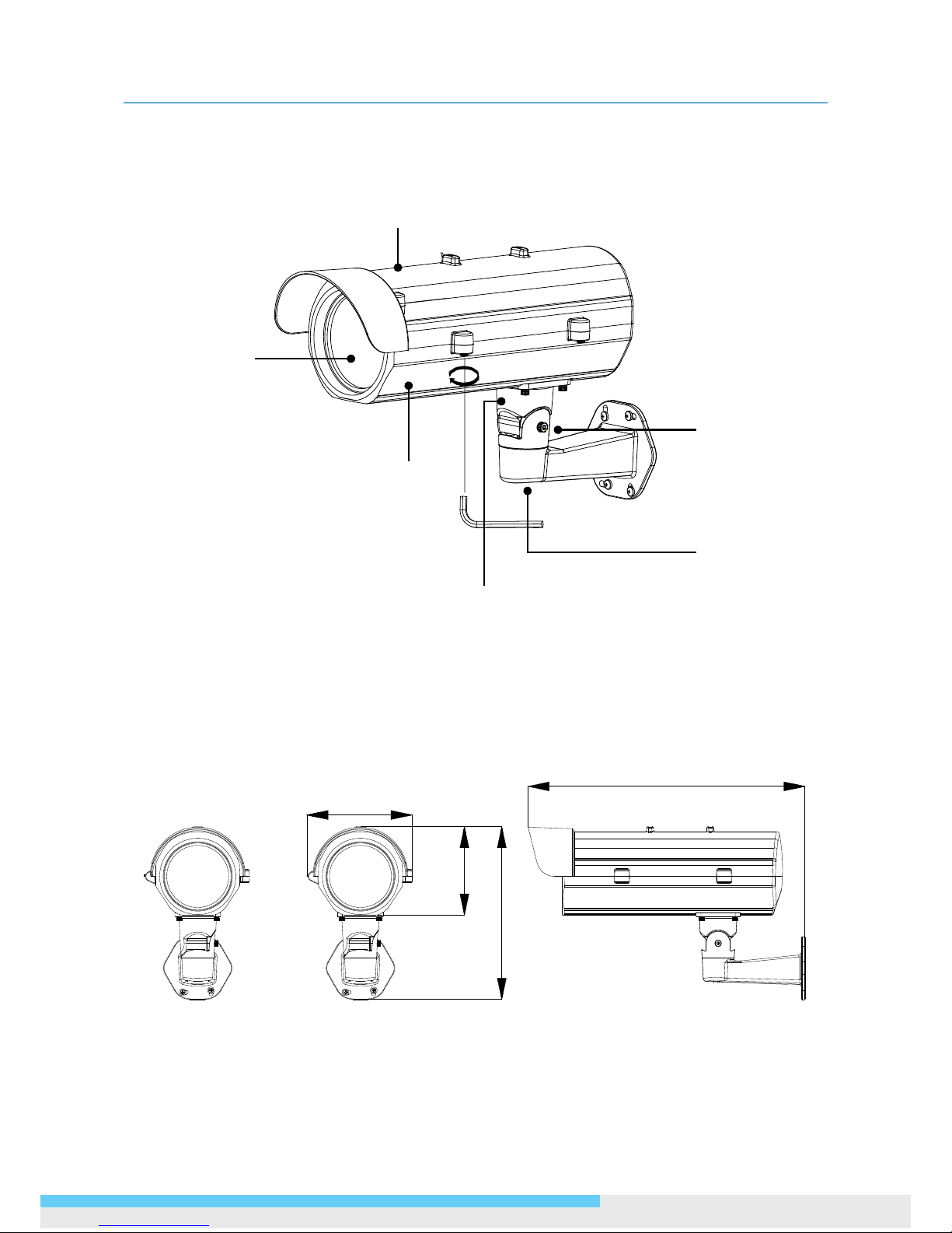
The gure above is the illustration of the housing, which may be used with most of ICR real Day and
Night cameras.
Dimensions
Unit: mm
175
460
147
286
Tempered
Glass
Top Cover
Bottom
Cover
Tilt Adjustment
Screw
Pan Adjustment
Screw
Bracket
Page 8

1. Overview
8 User Manual
Specications
LPR615
Video
Sensor Type 1/2.7" image sensor optimized for low-light performance
Active Pixels 1920x1080 (HxV)
Compression H.264 / MPEG4 / Motion JPEG
Streaming Triple simultaneous streams
Resolution 1080p, SXVGA, 720P, XGA, SVGA, D1, VGA, 2CIF, CIF
Max. Frame Rate 2MP 16:9 (1920x1080) at 30 fps (NTSC) and 25 fps (PAL)
Day/Night
CBR/VBR
Day/Night Mode
Mechanical (ICR) D/N Control
Shutter Time
Auto/ Forced BW/ Forced Color/ External
Minimum Illumination
1/10000s to 1/3.75s selectable (60Hz);
1/10000s to 1/3.125s selectable (50Hz)
Video Output
0.08 Lux @30IRE; 0.20 Lux @50IRE
(Shutter Speed: 1/15 sec)
Bit Rate Control
NTSC: 720 X 480 @30fps; PAL: 720 X 576 @25fps
Lens
Lens Type Built-in; Varifocal
Focal Length, Fnumber
f=8-80mm, F1.6
Focus / Zoom Manual
View Angle (FOV) H: 38.16°(Wide)~3.5°(Tele)/V:22.05°(Wide)~2.09°(Tele)
IRIS Control DC IRIS
Audio
Audio Communication Two-Way Mono Audio, Full-Duplex
Compression G.711, PCM, 8kHz
Audio In/Out External microphone and speaker
Image Enhancement
Image Settings
AES, AWB, AGC
Exposure Mode: AES / ALC / Flickerless / Manual;
White Balance: Auto / Manual;
Backlight Compensation
Congurable Brightness, Contrast, Hue, Saturation, and
Sharpness
Gamma Correction
Digital WDR Yes; 5 level sensitivity
Privacy Zone Yes; customized threshold privacy zone
Frequency Control 50Hz, 60Hz
Date & Time Stamp Yes
Intelligent Video & Event Management
Motion Detection 5 x 5 zones, 5 level sensitivity or customized threshold
Blur Detection Customized sensitivity in seconds
Ethernet Detection Network loss detection
Smart Encoding Congurable ROI for better picture quality
Others Snapshot, Smart Focus, e-PTZ, Optimized i-frame setting
Events
Motion detection, face detection, audio detection, blur
detection, Ethernet detection, external alarm
Event Actions
File upload via FTP, SMTP and SD Card; Notication via
email, HTTP and TCP External output activation; Video
and audio recording to SD Card
Store Category
Alarm / Motion / Schedule/ Un-interrupt recording
Stores video clips and snapshots
Intelligent Trafc Mode
Intelligent Trafc Mode
4 modes including City Surveillance, Highway, Entry/Toll
and Parking lot
Proles
4 customizable parameters options to meet various eld
conditions for best performance on 24/7 application
Local Storage
Memory Card Slot Micro SD / Micro SDHC Card up to 32 GB
Memory Card Overwrite
Yes
Network
Protocol
IPv4, TCP/IP, UDP, HTTP, SMTP, DNS, DHCP, NTP, FTP, RTP,
RTSP, RTCP, ICMP, UPnP
Ethernet
10Base-T/100Base-TX Ethernet connection for LAN /
WAN, RJ-45
ONVIF Yes
Browser IE Browser 6.0 or Above
Security Two-level access with password protection
I/O & Controls
Power Screwless Terminal block
Power LED Indicator Yes
Alarm In/Out Terminal Block 2 in / 1 out
Network RJ-45 with LEDs
Audio In/Out 3.5mm Phone Jack 1 in / 1 out
RS-485 Reserved
Analog Video BNC X1, 1.0Vp-p, 75Ω
Reset Within 5 secs to reboot; More than 5 secs to load default
Power
Power Requirement AC 24V ± 10%
Power Consumption
(Max.)
35W (Max.)
Mechanism
Dimensions(WxDxH) 114 x 66 x 65 mm (4.5" x 2.6" x 2.6")
Weight 4400g (9.7lb)
Protection IP66
Battery Backed-up Realtime Clock
Yes; External RTC
Environment
Operating Temp. -40ºC ~ 50ºC (-40ºF ~ 122 ºF)
Operating Humidity 10~ 90% RH
Storage Temp. -20°C ~ 60°C (-4°F ~ 140°F)
Regulatory
Approvals CE, FCC, RoHS
Ordering Information
Model No.
NTSC: LPR615-N2-US-MES,
PAL: LPR615-P2-EU-MES
Accessories
Easily adjustable 2-axis and cable-concealed bracket with
standard package
Page 9

1. Overview
User Manual 9
LPR610
Video
Sensor Type 1/2.7" image sensor optimized for low-light performance
Active Pixels 1920x1080 (HxV)
Compression H.264 / MPEG4 / Motion JPEG
Streaming Triple simultaneous streams
Resolution 1080p, SXVGA, 720P, XGA, SVGA, D1, VGA, 2CIF, CIF
Max. Frame Rate 2MP 16:9 (1920x1080) at 30 fps (NTSC) and 25 fps (PAL)
Day/Night
CBR/VBR
Day/Night Mode
Mechanical (ICR) D/N Control
Shutter Time
Auto/ Forced BW/ Forced Color/ External
Minimum Illumination
1/10000s to 1/3.75s selectable (60Hz);
1/10000s to 1/3.125s selectable (50Hz)
Video Output
0.08 Lux @30IRE; 0.20 Lux @50IRE
(Shutter Speed: 1/15 sec)
Bit Rate Control
NTSC: 720 X 480 @30fps; PAL: 720 X 576 @25fps
Lens
Lens Type
Built-in; Varifocal
Focal Length, Fnumber
f=15-50mm, F1.5
Focus / Zoom
Manual
View Angle (FOV)
H: 20.01°(Wide)~6.09°(Tele) / V: 23.6°(Wide)~3.8°(Tele)
IRIS Control
DC IRIS
IR LEDs
LED Quantity
96 pcs (850nm)
IR Distance
15-30m (50-100ft)
IR turn on status
Under 5 Lux by auto control
LED Life
More than 10,000 hours (50°C)
Audio
Audio Communication Two-Way Mono Audio, Full-Duplex
Compression G.711, PCM, 8kHz
Audio In/Out External microphone and speaker
Image Enhancement
Image Settings
AES, AWB, AGC
Exposure Mode: AES / ALC / Flickerless / Manual;
White Balance: Auto / Manual;
Backlight Compensation
Congurable Brightness, Contrast, Hue, Saturation, and
Sharpness
Gamma Correction
Digital WDR Yes; 5 level sensitivity
Privacy Zone Yes; customized threshold privacy zone
Frequency Control 50Hz, 60Hz
Date & Time Stamp Yes
Image Enhancement
Image Settings
Exposure Mode: Auto Exp./Manual Exp./Auto IRIS;
White Balance: Auto/Manual;
Backlight Compensation: 5x5 zones selectable;
Gain, Sharpness, Saturation, Brightness, Contrast: 255
level sensitivity
WDR
Digital WDR; 5 level sensitivity
DNR
-
Privacy Zone
Yes; customized threshold privacy zone
Image Orientation
Mirror, Flip
Frequency Control
NTSC(60Hz)/ PAL(50Hz)
Date & Time Stamp
Yes
Intelligent Video & Event Management
Motion Detection Yes, 5-level sensitivity
Others
Ethernet / Blur / Audio Detection, Snapshot, Smart Focus,
e-PTZ, Optimized i-frame setting
Event Actions
File upload via FTP, SMTP and SD Card; Notication via
email, HTTP and TCP External output activation; Video
and audio recording to SD Card
Store Category
Event snapshot, Edge recording, Manual Snapshot,
Manual Recording
Intelligent Trafc Mode
4 modes including City Surveillance, Highway, Entry/Toll
and Parking lot
Prole
4 customizable parameters options to meet various eld
conditions for best performance on 24/7 application
Local Storage
Memory Card Slot Micro SD / Micro SDHC Card up to 32 GB
Memory Card Overwrite
Yes
Network
Protocol
IPv4, TCP/IP, UDP, HTTP, SMTP, DNS, DHCP, NTP, FTP, RTP,
RTSP, RTCP, ICMP, UPnP
Ethernet
10Base-T/100Base-TX Ethernet connection for LAN /
WAN, RJ-45
ONVIF Yes
Browser IE Browser 6.0 or Above
Security Two-level access with password protection
I/O & Controls
Power Screwless Terminal block
Power LED Indicator Yes
Alarm In/Out Terminal Block 2 in / 1 out
Network RJ-45 with LEDs
Audio In/Out 3.5mm Phone Jack 1 in / 1 out
Analog Video BNC X1, 1.0Vp-p, 75Ω
Reset Within 5 secs to reboot; More than 5 secs to load default
Power
Power Requirement AC 24V ± 10%
Power Consumption
(Max.)
45W (Max.)
Mechanism
Dimensions(WxDxH) 422 x 174 x 145mm (16.6" x 6.9" x 5.7")
Weight 6000g (13.22lb)
Protection IP66
Environment
Operating Temp. -40ºC ~ 50ºC (-40ºF ~ 122 ºF)
Operating Humidity 10~ 90% RH
Storage Temp. -20°C ~ 60°C (-4°F ~ 140°F)
Regulatory
Approvals CE, FCC, RoHS
Ordering Information
Model No.
NTSC: LPR610-N2-US-MES;
PAL: LPR610-P2-EU-MES
Accessories
Easily adjustable 2-axis and cable-concealed bracket with
standard package
Page 10
2. Installation
10 User Manual
2. Installation
Installation of the Camera and Bracket
Wiring Cables
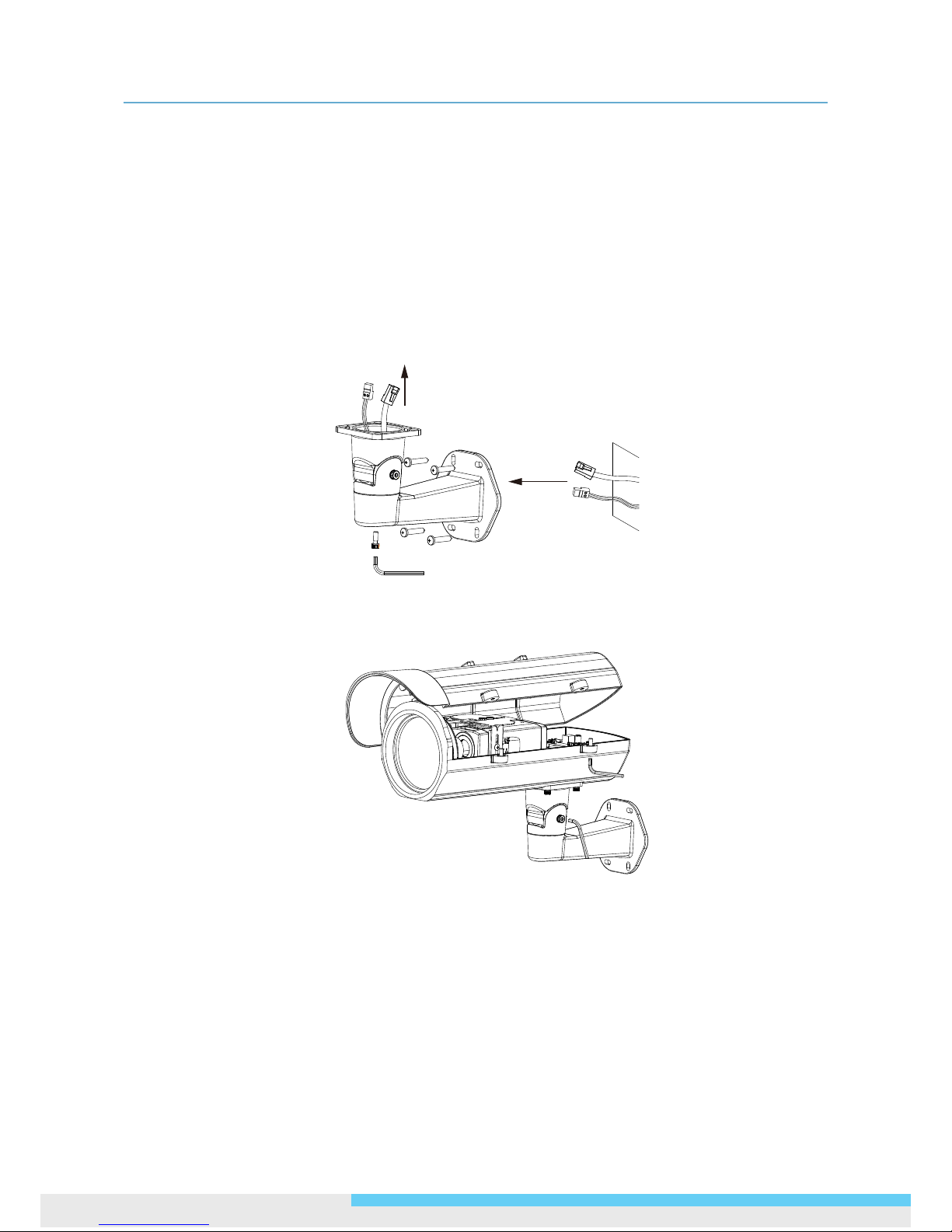
1. Take the bracket from the box and put the power cable and Ethernet cable through the bracket
and then x the bracket to the wall (Loose the screws of the bracket for easy assembly if
necessary).
2. Take out the housing and open the side cover with the hexagonal wrench.
Page 11
2. Installation
User Manual 11
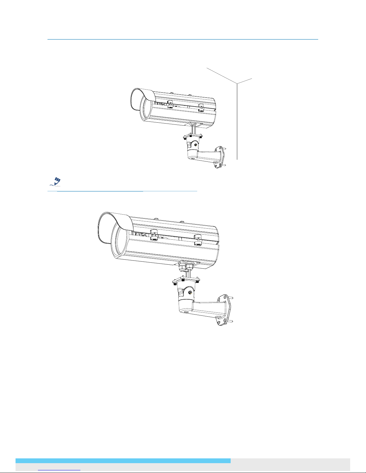
3. Put the Ethernet cable through the bottom of the housing and let it pass from the hole. Make
connection of power by plugging the terminal block into the power socket.
Note
For waterproof installation, use the provided spacer and stick it right by the outlet. Then install the
three glands to get the power cable and Ethernet cable pass through the hole of the gland covers.
Page 12
2. Installation
12 User Manual
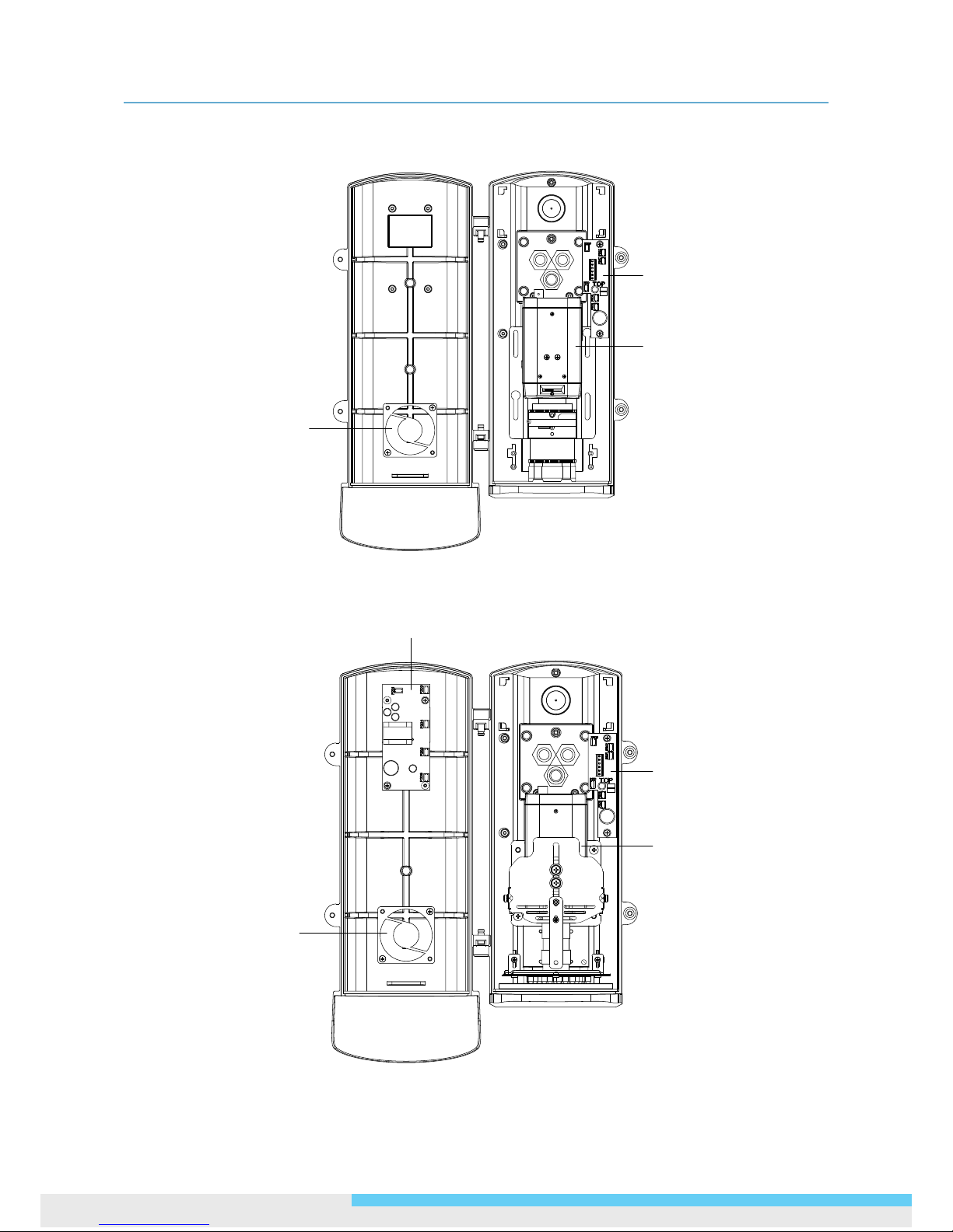
4. Open the side cover and you can see the housing inner part as the gure shown below.
LPR615 Inner Part Denition
LPR610 Inner Part Denition
Fan
Camera
Camera
Fan
IR LED driver board
I/O board
I/O board
Page 13
2. Installation
User Manual 13
I/O Contacts
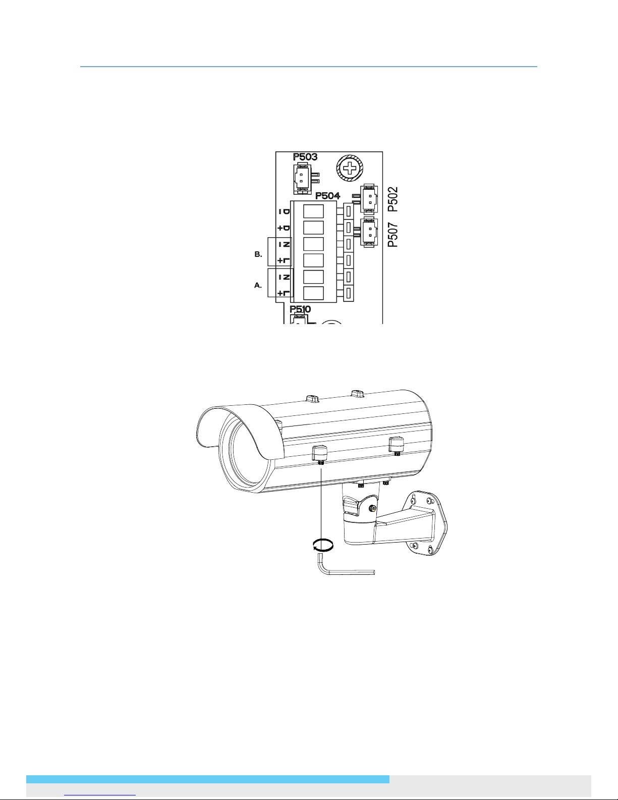
Connect the power cable to the power port of the AC24V camera and to the A section (L+: power +/
N-: power- ) as below. And connect the outside AC24V power supply to the section B( L+: power+/
N-: power- ).
Contact positions on the heater board
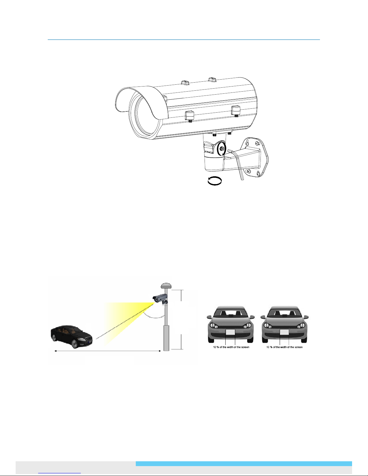
5. After you have nished wiring the Ethernet cable, close the side cover and use the provided
screws to x the housing on the bracket with the hexagonal wrench.
Page 14
2. Installation
14 User Manual
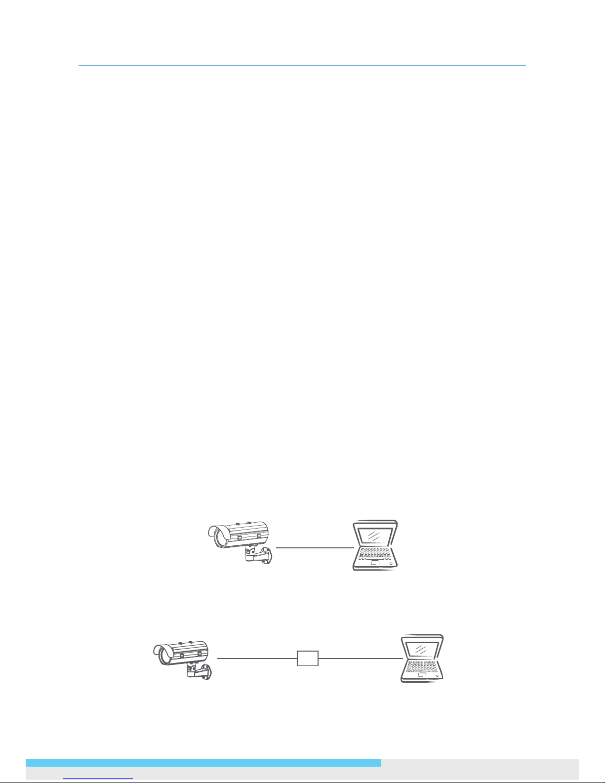
6. Loosen the pan and tilt adjustment screws of the bracket to adjust the angle of the housing and
then tighten the screws.
Recommended Installation Distance
LPR615 & LPR610 is built in with a 8 ~80mm and 15 ~50mm lens respectively, which can capture
a wide 24~26 ft. (7.5~8 meters) eld. To ensure an optimal view, please adjust the lens under the
conditions we suggest.
1. The camera height should be higher than 11.5 ft. (3.5 meters).
2. The width of the license plate should cover approximately 10% of the width of the screen.
3. Vertical angle should not be less than 40 degrees.
Height
11.5~20 ft.
(3.5~6 meters)
Distance: 39~60 ft.
40°(min.)
Page 15
2. Installation
User Manual 15
Initial Conguration
Before connecting the camera to your network infrastructure, it’s suggested that you connect the
camera to a computer rst to perform initial congurations.
1. To access the camera, the PC must be on the same network segment as the camera. The default
IP address of the camera is a static one (192.168.1.30). Congure your PC’s IP address as
192.168.1.X (X is a number between 2 to 254 excluding 30) and subnet mask as 255.255.255.0,
and then your PC should be able to access the camera.
• IP Address: 192.168.1.30
• Subnet Mask: 255.255.255.0
2. Using an Ethernet cable, connect the camera to the computer.
The LAN port of the camera supports auto MDI/MDIX so there is no need to use a cross-over
cable.
3. On the PC, launch a web browser and enter the IP address of the camera in the URL eld:
http://192.168.1.30
4. When prompted for login, enter the default user name: admin and password: 1234 to log in.
Note that the user name and password are case-sensitive.
5. Congure the settings to meet your requirements. For more information, refer to the User Manual
on the provided CD-ROM.
Network Deployment
There are many different ways that you can connect the camera to your network, depending on
your applications requirements. You should always set the camera’s network settings according to
your network congurations. The following diagrams depict some typical applications with guidelines
on network settings. For more information on network settings, always consult with your network
administrator or ISP as required.
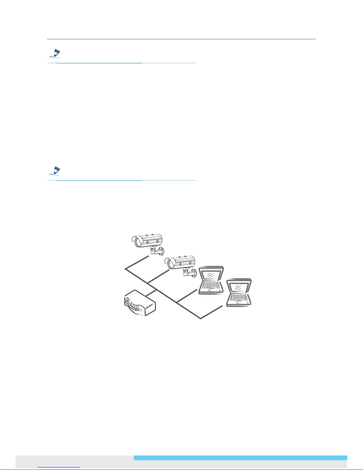
Type 1: Direct Connection to a PC
Directly connect the RJ-45 cable of the camera to a PC.
To extend the connection length, you should use an RJ-45 female/female coupler to connect two
category 5/5e UTP/STP cables together.
RJ-45 Coupler
Page 16
2. Installation
16 User Manual
Note
Although an RJ-45 coupler is used to extend the connection length, the total length between the PC
and the IP camera must not exceed 100 meters (328 feet). The LAN port of the camera supports auto
MDI/MDIX (Medium dependent interface crossover) so there is no need to use cross-over cable.
To access the camera, the PC must be on the same network segment as the camera. The default IP
address of the camera is a static one (192.168.1.30). Congure your PC’s IP address as 192.168.1.X
(where X is a number between 2 to 254 excluding 30) and subnet mask as 255.255.255.0, and then
your PC should be able to access the camera.
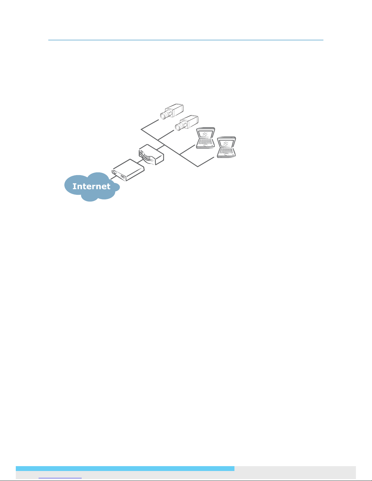
Type 2: Connection to LAN
To add the camera(s) to an existing LAN, just connect the camera(s) to the router, switch or hub on
your network.
Note
The LAN port of the camera supports auto MDI/MDIX (Medium dependent interface crossover) so
there is no need for an uplink port or the use of a cross-over cable.
Assign an IP address to your camera following your network IP allocation policy. The IP address can
be manually specied by users or by a DHCP server, if available on your network.
Then, you can monitor and mange the camera via a web browser from a local PC.
Router/Switch/Hub
Page 17
2. Installation
User Manual 17
Type 3: Remote Connection via the Internet
If the network where the camera resides is connected to the Internet, you can also provide remote
access to your camera over the Internet.
Typically a broadband router has a built-in DHCP function to assign a local IP address to your camera.
You can alternatively assign a xed IP address to the camera to prevent it from frequently changing.
Router
xD S L/Ca b le
Modem
To access the camera from a local PC, simply use the local IP address of the camera.
To enable remote access, you must congure your router/rewall to forward an incoming request to
that xed local IP address of the camera. Therefore, when an external host sends a request to access
your camera, the request will rst reach the router’s external IP address and then be forwarded to
the local IP address of the camera.
Port forwarding is based on the service you want to provide. For example, forward HTTP port to
enable remote web access to your camera, or RTSP port to enable access to video/audio streams
from the camera.
If your camera is congured to use a non-standard HTTP port, then you have to forward that port
accordingly.
Page 18
2. Installation
18 User Manual
Accessing the Camera for the First Time
The camera comes with a web-based setup utility, allowing you to view the video of the camera and
congure the camera for optimal use in your environment.
To access the camera’s web-based control utility, you need a PC that meets the following
requirements:
Operating System: Windows Vista® or XP
Browser: Internet Explorer Version 6.0 or later
CPU: Intel® Pentium® 4 Processor 2GHz or higher
RAM: 512 MB or more.
Then take the following steps to connect your PC to the camera.
Step 1: Make the connection
For initial setup purposes, connect one end of an Ethernet cable to the RJ45 connector of the camera
and the other end to the LAN port on your PC.
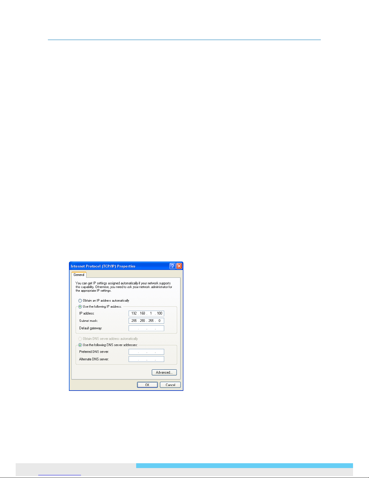
Step 2: Congure your PC’s IP address
The camera uses a default IP address of 192.168.1.30 and subnet mask of 255.255.255.0. To have
your PC on the same network with the camera, congure your PC’s IP settings as below:
IP address: 192.168.1. X, where X is a number between 2 to 254, excluding 30.
Subnet mask: 255.255.255.0.
Ignore all other settings and click OK.
Page 19
2. Installation
User Manual 19
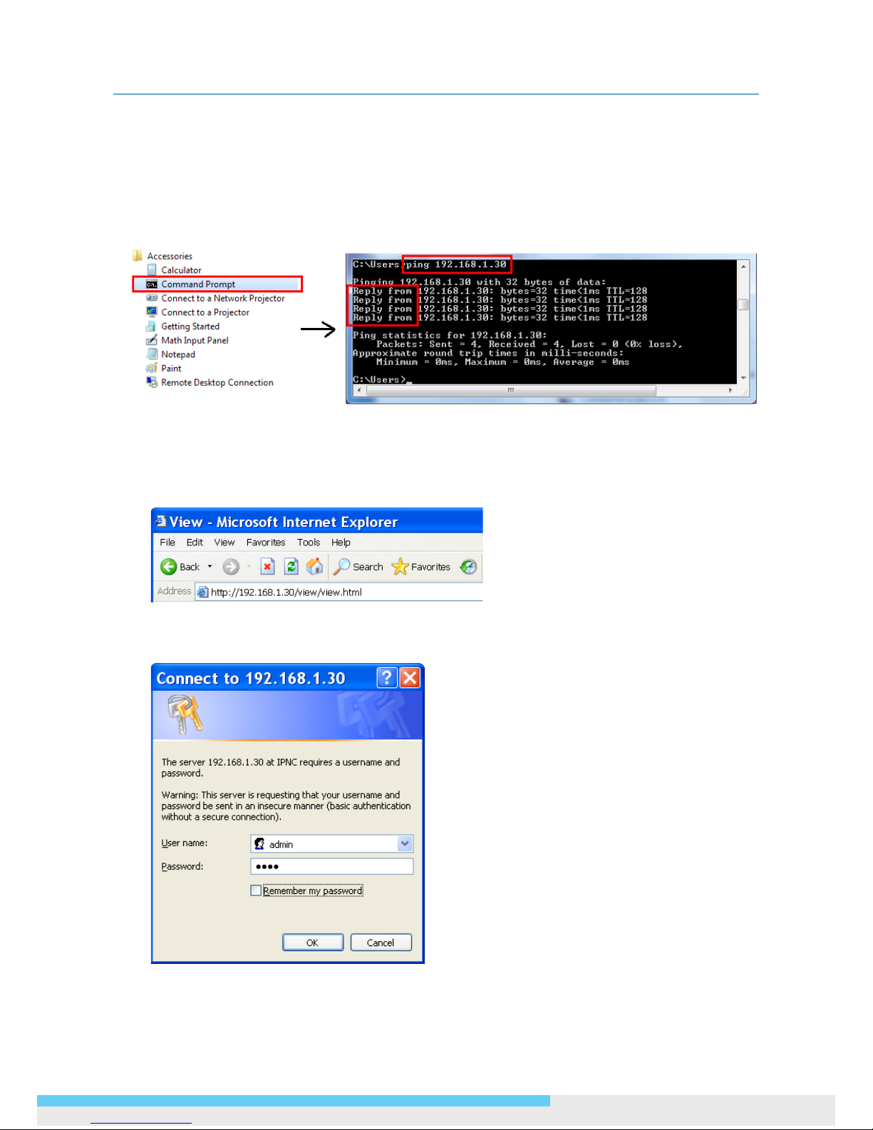
Step 3: Link Verication between PC and Camera
1. Launch the Command Prompt by clicking the Start menu, Programs, Accessories and then
Command Prompt.
2. At the prompt window, type
ping x.x.x.x
, where x.x.x.x is the IP address of the camera (the
default is 192.168.1.30).
If the message of “Reply from…” reponds, it means the connection is established.
Step 4: Accessing the Camera from IE Browser
Open the IE browser and enter the IP address of the camera in the URL eld. The default is
192.168.1.30.
When prompted for login, enter the user name and the password (The defaults: admin, 1234). Note
that the user name and password are case-sensitive.
Page 20
2. Installation
20 User Manual
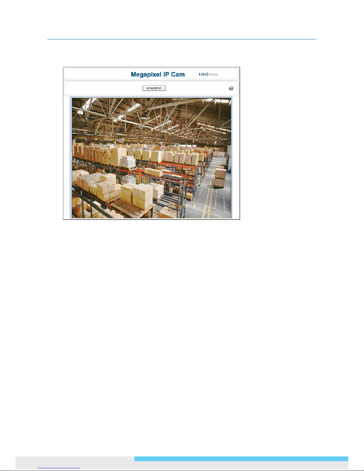
Upon successful login, you will see the live view screen shown below, which is an example for series
introduction.
Using “IP Finder” to Manage Cameras
IP Finder is a management tool included on the product CD. It is designed to manage your network
cameras on the LAN. It can help nd multiple network cameras, set IP addresses, show connection
status and manage rmware upgrades.
Installing IP Finder
Before proceeding, make sure your operating system is Windows Vista or Windows XP.
To install the software, simple locate and double-click the IP Finder setup le on the provided CD.
Then follow the on-screen prompts to proceed.
Using IP Finder
To launch IP Finder, double-click the IP Finder shortcut on the desktop or click Start > Programs >
IP Finder > IP Finder.
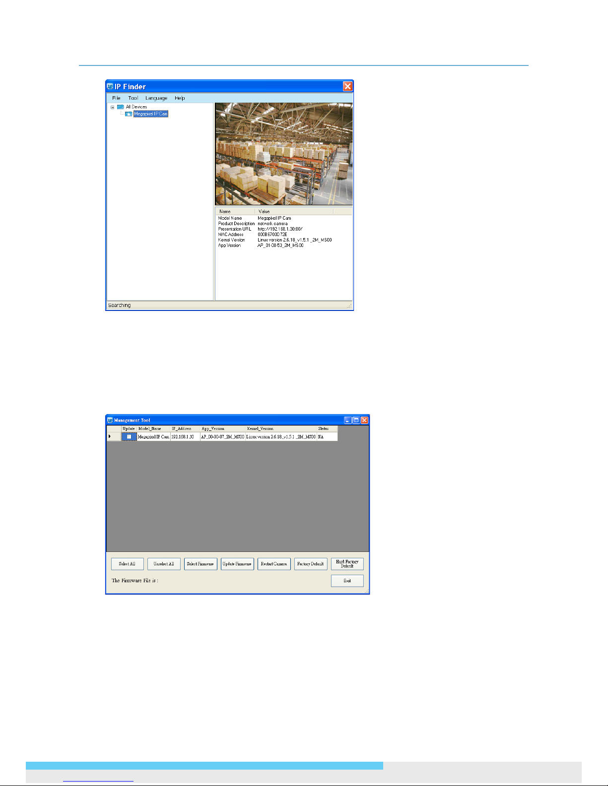
After you launch IP Finder, it will search for all the available cameras on the same network. Click
the plus sign next to “All Devices” to expand the menu and display all the found cameras.
Clicking a target camera will show the live view (if available) and the detailed information of the
camera, including the MAC address. Each camera comes with a unique MAC address, which is
indicated on the product label. It helps identify which camera is currently accessed, particularly when
multiple cameras are connected on your network.
Page 21
2. Installation
User Manual 21
The Tool menu of the IP Finder allows you to perform these tasks:
Search Network: This option allows you to search the cameras on the network.
Set Master ID and Password: Allows you to set a master ID and password for managing the
cameras with IP Finder.
Management Tool: Allows you to restart the camera, update rmware, reset all of the camera
settings to default (except network settings) and reset all of the camera parameters to default.
For an individual camera, right-click the camera and a menu will provide these options:
Go to Presentation URL: Launch IE browser to access the web-based utility of the camera.
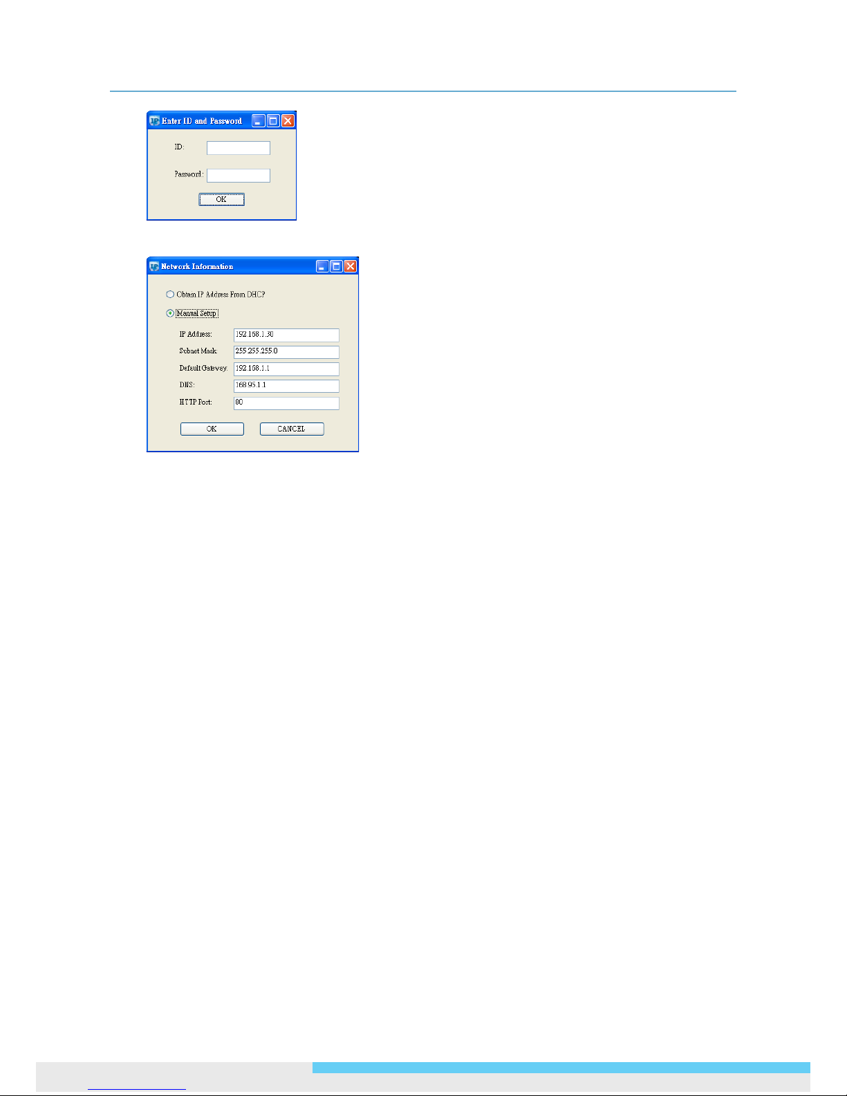
Set Device ID and Password: Set the login ID and password for managing the camera with IP
Finder.
Page 22
2. Installation
22 User Manual
Network Information: Allows you to congure the camera’s network settings.
Page 23
3. Web-based Interface
User Manual 23
3. Web-based Interface
3.1 Overview
3.1.1 Main Screen
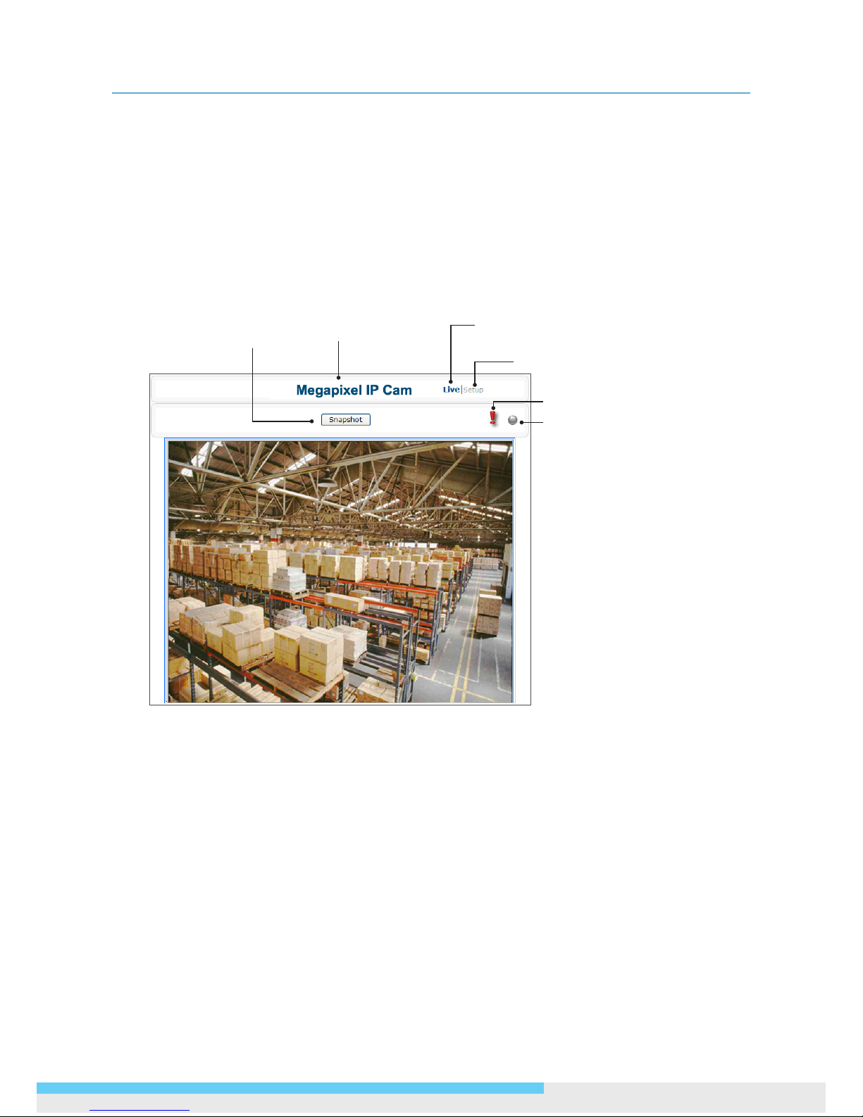
After you log in to the camera’s web-based control utility, you will rst see the live view screen of the
camera. The screen below is an example for series introduction.
Snapshot button
Setup button
Live view video
Alarm Indicator
Recording Indicator
Camera name
The live view screen of the utility provides these options:
Snapshot: Pressing this button takes a snapshot of the current live view screen.
Live: Pressing this button displays the live view of the camera.
Setup: Pressing this button allows you to access the setup page.
Camera name: Displays the name of the camera.
Recording Indicator: Turns red when the recording is proceeding.
Alarm Indicator: Appears when an alarm is triggered.
Live view video: Shows the live view of the camera.
Note that the accessibility to the options varies according to the login account.
Viewer: Allowed to view only the live view screen. Access to other options is restricted.
Administrator: Can access all the options on the live view page and make congurations on the
setup pages.
Page 24
3. Web-based Interface
24 User Manual
3.1.2 Setup Menu
The Setup options are categorized into six groups: ANPR/LPR, Image, Network, System, Event
and Recording. Clicking the name will expand its sub-menu. See the ensuing sections for more
information.
3.1.3 Applying Settings
Each conguration page provides a Save button. Settings are applied right after you press the Save
button. And the browser will refresh to load the latest setting or otherwise pop up the “Save OK”
message to indicate that settings have been applied.
3.2 ANPR/LPR Settings
3.2.1 ANPR/LPR
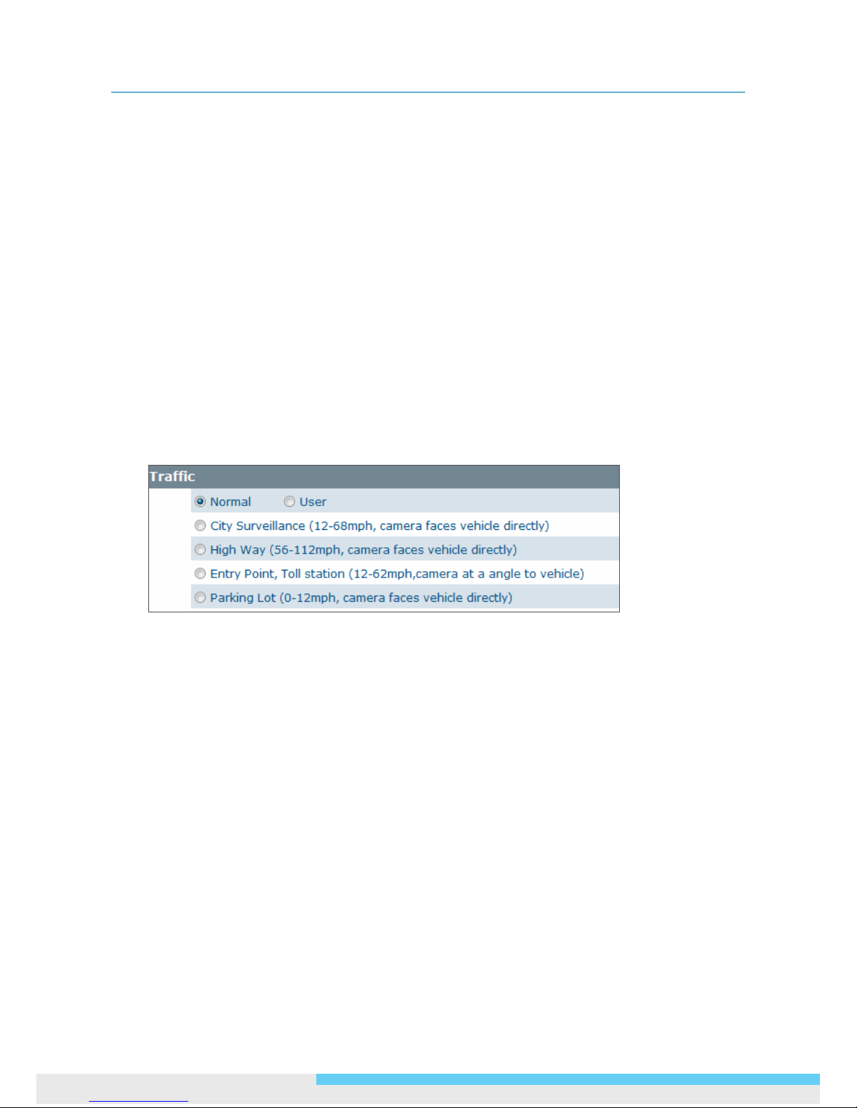
Trafc
Built in with 4 preset modes with optimizedparameter settings in accordance with different car speeds
and camera angles to help inexperienced users easily achieve the best capture results in these
preprogrammed scenarios, e.g. city surveillance, highway, entry point/toll station, and parking lot.
Normal: Set the exposure mode to improve image quality.
User: Allows you to set exposure mode and desired time frames to meet different conditons
during a day
City Surveillance: Applied to the speed from 20 kmph to 110 kmph (12mph to 68mph). Please
set the camera facing vehicle directly.
High Way: Applied to higher auto speed environment, such as freeway. The speed is around 90
kmph to 180 kmph (56mph to 112mph). Please set the camera facing vehicle directly.
Entry Point, Toll station: Applied to the speed from 20 kmph to 110 kmph (12mph to 68mph).
Please set the camera facing the car front with angle.
Parking Lot: Applied to parking area. The auto speed is around 0 kmph to 20 kmph (0mph to
12mph). Please set the camera facing vehicle directly.
Page 25
3. Web-based Interface
User Manual 25
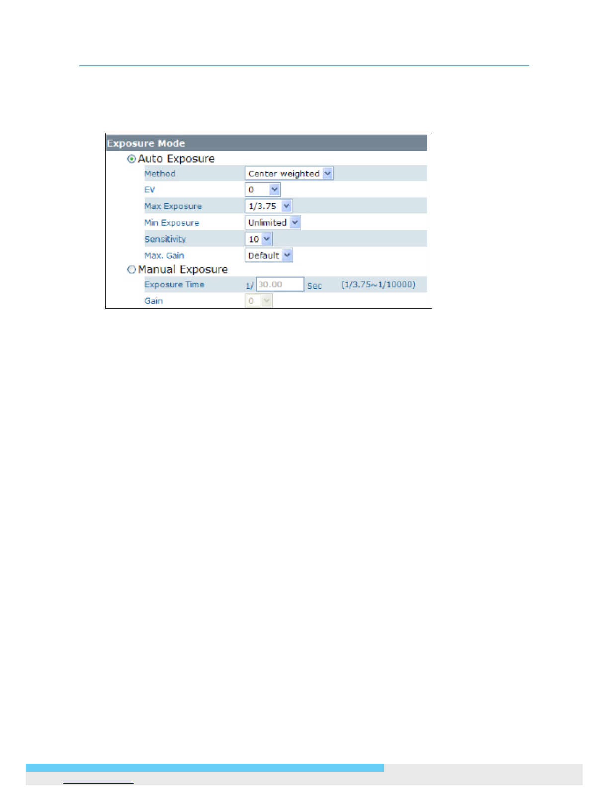
Exposure Mode
The Exposure Mode allows you to congure the exposure settings to meet the image quality
requirements in relation to lighting and other considerations.
Auto Exposure Settings
Method: Select which area of the image will be used to measure the amount of light to achieve
best exposure.
• Center Weighted: Exposure metering is averaged over the entire frame but emphasis is
placed on the central area.
• Object Targeted: This option meters the exposure based on the targets you specify. When
this option is selected, dene your target by clicking squares displayed on the image and
then press Save Spot Window to save the setting.
EV: In a scene with predominantly light or dark areas, the image will be underexposed or
overexposed, causing an image to be too dark or bright. In such situations, you can adjust a
compensation value to optimize the exposure. Decrease the value if images appear too light
(overexposed). Increase the value if images are too dark (underexposed).
Max/Min. Exp: Select the maximum / minimum exposure time according to the light source. The
selectable value will change according to the frequency setting under Image > Basic Settings.
Sensitivity: Select how sensitive the camera reacts to the light. A higher value enables the
camera to be more sensitive to the light conditions and adjust the exposure in the shortest time
interval.
Max Gain: Specify the maximum amount of amplication applied to the image. A high level of
gain allows images to be viewable in very low light, but will increase the image noise.
Manual Exposure Settings
Exposure Time: Enter a desired exposure time.
Gain: Select a gain value from 0 to 16. A high level of gain allows images to be viewable in very
low light, but will increase image noise.
Page 26
3. Web-based Interface
26 User Manual
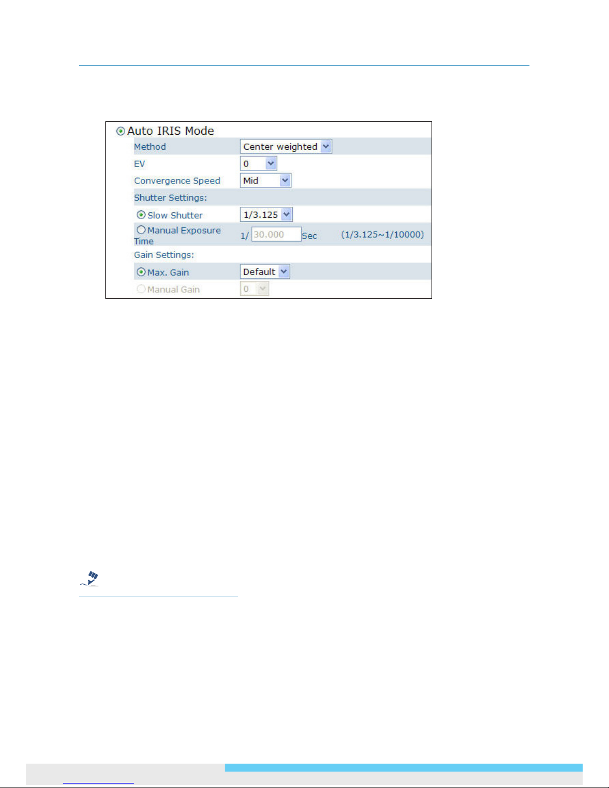
Auto IRIS Mode
Select Auto IRIS Mode to congure the exposure settings with the auto iris control enabled.
Method: Select which area of the image will be used to measure the amount of light to achieve
best exposure.
• Center Weighted: Exposure metering is averaged over the entire frame but the emphasis is
placed on the central area.
• Object Targeted: Dene your target by clicking squares displayed on the image and then
press Save Spot Window to save the setting.
EV: Decrease the value if images appear too light (overexposed). Increase the value if images are
too dark (underexposed).
Convergence Speed: Select the lens’ convergence speed from the drop-down list. Higher the
convergence speed, the faster the lens iris opening responds to changes in light levels.
Shutter Settings:
Slow Shutter: Set the exposure time from a set of xed shutter speeds.
Manual Exposure Time: Manually input a desired exposure time.
Gain Settings:
Max. Gain: Specify the maximum amount of amplication applied to the image. A high level of
gain allows images to be viewable in very low light, but will increase the image noise.
Manual Gain: Select a gain value from 0 to 16.
Note
For optimal LPR results, users are recommended to adjust the Manual Exposure Time and Manual
Gain appropriate for the actual environment at the monitored site.
Page 27
3. Web-based Interface
User Manual 27
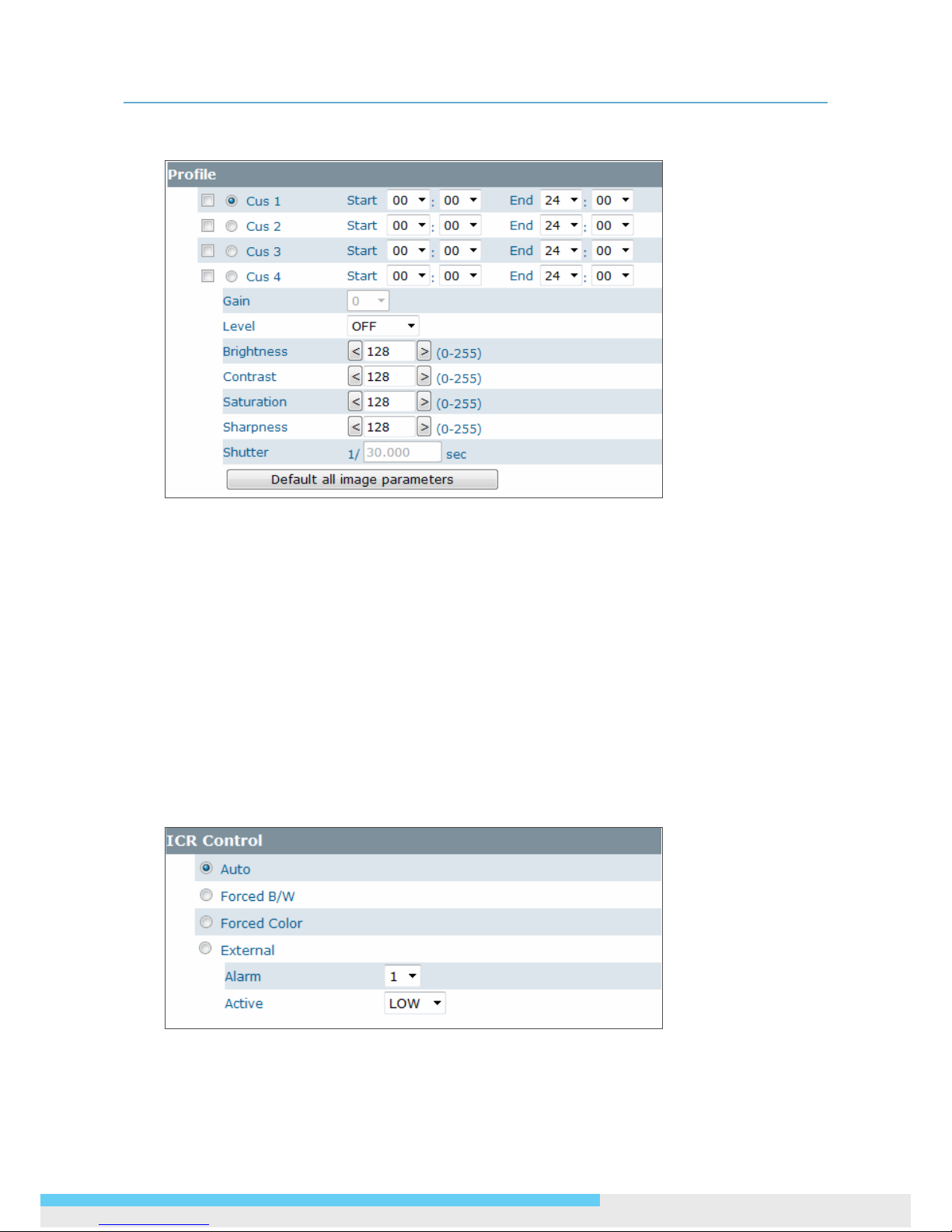
Prole
Prole Setting provides users with exibility to customize and apply different parameter settings at
up to 4 different time frames in order to meet the variation in light, weather and other environmental
factors during a day.(Unavailable when trafc mode is normal)
• Gain: Unavailable
• Brightness: Adjust the image brightness level.
• Contrast: Adjust the image contrast level.
• Saturation: Adjust the image saturation level.
• Sharpness: Adjust the image sharpness level.
• Shutter: Unavailable
• Default All Image parameters: Pressing this button will restore all the image settings to
the defaults.
ICR Control
The camera incorporates an IR cut lter. In ICR Control you can specify how the camera switches
between color and black/white modes.(Unavailable when trafc mode is normal)
Page 28
3. Web-based Interface
28 User Manual
Auto: Allows the camera to automatically switch between color and black/white modes.(Available
only when trafc mode is user)
Forced B/W: Forces the camera stay in black/white mode at all times.
Forced Color: Forces the camera stay in color mode at all times.
External: Enable this option if an external alarm input device is connected to control the IR cut
lter.
• Alarm: Set alarm input as 1 or 2 according your actual connection.
• Active: Select (electricity) current status as high or low to dene active status.
3.3 Image Settings
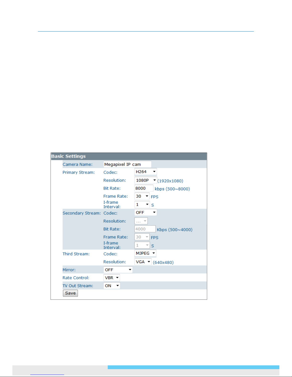
3.3.1 Codec
The Codec page allows you to congure the video streams for the camera. You can optionally
congure a secondary or third stream to a resolution as required by your third-party device or
software.
Camera Name Settings
Enter a descriptive name of the camera. Note that if you want to make the camera ONVIF
compliant (see Network > ONVIF ), no space is allowed in the camera name.
Page 29
3. Web-based Interface
User Manual 29
H.264 Codec Settings
Resolution: Click the drop-down menu to choose a resolution for the video.
Bit Rate: According to your bandwidth, specify a value for data transmission rate (kbps). Higher
value gets higher video quality but consumes more bandwidth.
Frame Rate: Choose the intended frame rate, i.e., the number of frames to transmit per second.
I-fram Interval: While keeping the same frame rate, you can specify longer I-frame interval
to achive reduced bit rate, optimized bandwidth consumption and minimized storage space
consumption. Generally, it’s recommended setting longer interval for less motion and sufcient
lighting conditions, and shorter interval for scenes with lots of motion and low lighting conditions.
Click the drop-down menu to select options including 1/2, 1, 2, 3, 4 seconds.
MPEG4 Codec Settings
Resolution: Click the drop-down menu to choose a resolution for the video.
Bit Rate: According to your bandwidth, specify a value for data transmission rate (kbps). Higher
value gets higher video quality but consumes more bandwidth.
Frame Rate: Choose the intended frame rate, i.e., the number of frames to transmit per second.
I-fram Interval: While keeping the same frame rate, you can specify longer I-frame interval
to achive reduced bit rate, optimized bandwidth consumption and minimized storage space
consumption. Generally, it’s recommended setting longer interval for less motion and sufcient
lighting conditions, and shorter interval for scenes with lots of motion and low lighting conditions.
Click the drop-down menu to select options including 1/2, 1, 2, 3, 4 seconds.
MJPEG Codec Settings
Resolution: Click the drop-down menu to choose a resolution for the video.
Quality: Set the image’s quality as High, Normal or Low.
Frame Rate: Choose the intended frame rate, i.e., the number of frames to transmit per second.
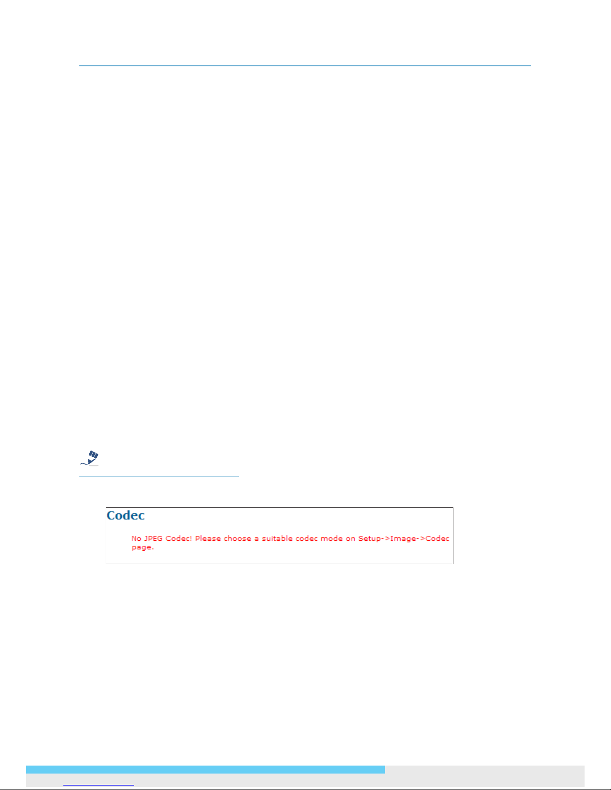
Note
1. Live View uses the MJPEG codec. If no streaming is using MJPEG, it will result in no video for Live
View.
2. If MJPEG is selected for both the primary stream and the third stream, Live View will always
display video using the third stream codec settings.
Page 30

3. Web-based Interface
30 User Manual
Refer to the tables below for selectable codec types for each streaming:
2MP Model Streaming Combination
Primary Secondary Third
Codec Resolution Codec Resolution Codec Resolution
MJPEG
1080P
OFF N/A
OFF N/A
H264
MPEG4
D1
VGA
2CIF
CIF
SXVGA
720P
XGA
SVGA
D1
OFF N/A
OFF N/A
MJPEG
VGA
CIF
H264
MPEG4
D1
VGA
2CIF
CIF
OFF N/A
MJPEG
VGA
CIF
MPEG4
1080P OFF N/A
OFF N/A
MJPEG
VGA
CIF
SXVGA
720P
XGA
SVGA
D1
OFF N/A
OFF N/A
MJPEG
VGA
CIF
H264
MPEG4
D1
VGA
2CIF
CIF
OFF N/A
MJPEG
VGA
CIF
H264
1080P
OFF N/A
OFF N/A
MJPEG
VGA
CIF
H264
MPEG4
D1
VGA
2CIF
CIF
OFF
N/A
MJPEG
VGA
CIF
SXVGA
720P
XGA
SVGA
D1
OFF N/A
OFF N/A
MJPEG
VGA
CIF
H264
MPEG4
D1
VGA
2CIF
OFF N/A
MJPEG VGA
Page 31
3. Web-based Interface
User Manual 31
Mirror Settings
This option allows you to mirror or ip the video image if required.
OFF: Turns off this function.
HORIZONTAL: Flips the images horizontally.
VERTICAL: Flips the images vertically.
BOTH: Flips the images vertically and horizontally.
Rate Control
Choose a bit rate control to manage your bandwidth usage.
Variable Bit Rate (VBR): VBR keeps the video stream quality as constant as possible by varying
bit rate. This mode ensures high quality image for motion scene and is often selected when image
quality demands priority. However, this mode requires more bandwidth in order to vary the bit
rate.
Constant Bit Rate (CBR): CBR maintains a specic and constant bit rate by varying the stream
quality. With CBR, streaming is smooth and network throughput is stable for any scene. This
mode is typically used with a limited bandwidth environment.
TV Output Stream
Turn on this option if you connect an analog monitor to the camera’s Video connector for video
output.
3.3.2 Exposure
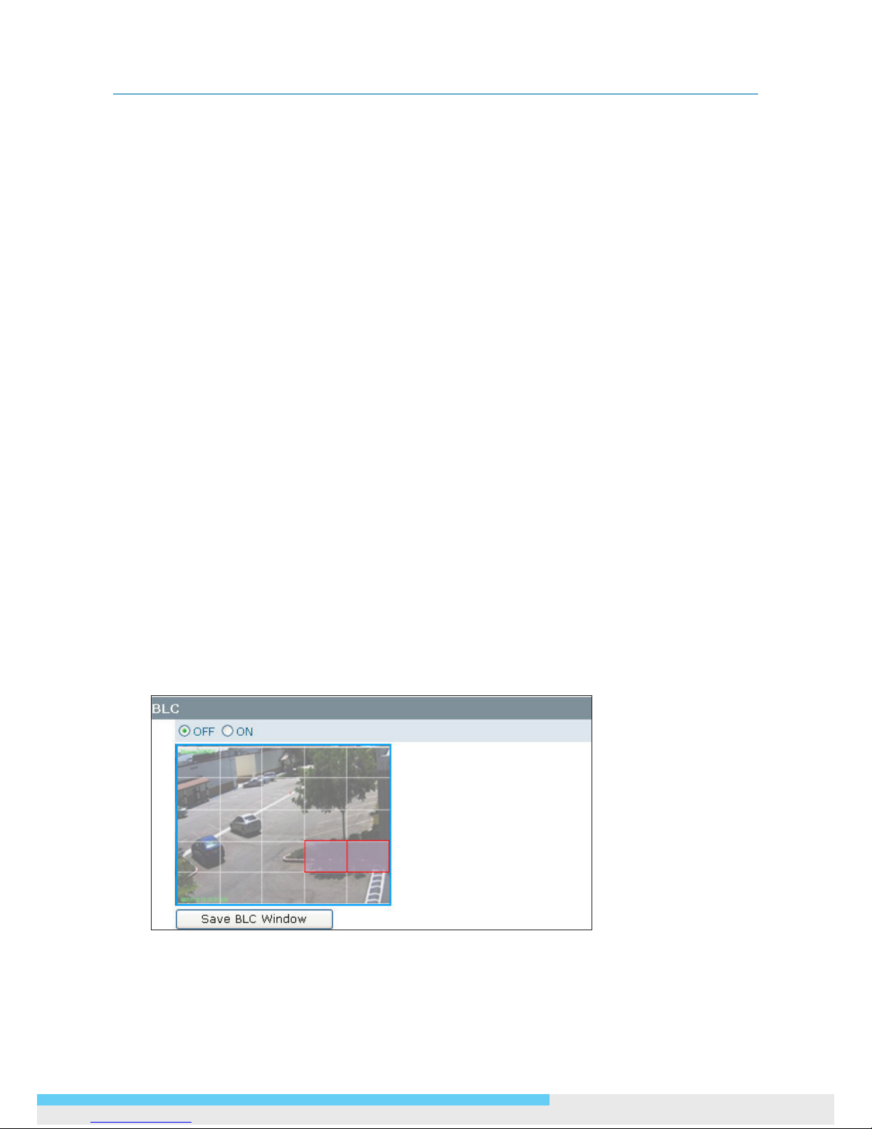
BLC (Backlight Compensation)
The Backlight Compensation function allows you to provide the optimal exposure of subjects under
back light circumstances.
OFF/ON: Choose to enable or disable the BLC function.
BLC area setting: BLC area refers to the dark area where more details are expected. Dene your
BLC area by clicking squares displayed on the screen and then press Save BLC Window to save
the setting.
Page 32
3. Web-based Interface
32 User Manual
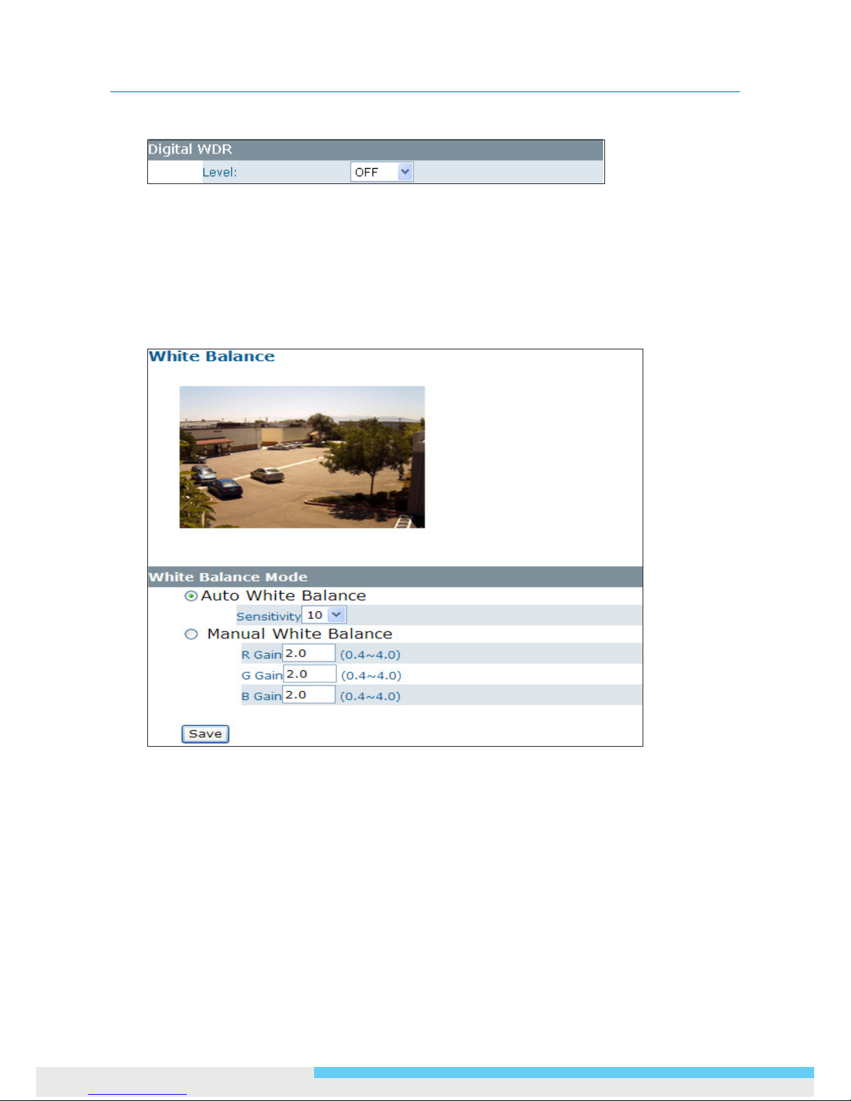
Digital Wide Dynamic Range
When there are both very bright and very dark areas simultaneously in the eld of view, you can
enable Digital Wide Dynamic Range (WDR) function. It optimizes an image to ensure that dark areas
are more visible while retaining details in bright areas.
Level: Depending on the contrast/dynamic range of a scene, you can select different level of
WDR. Higher level of WDR suits for higher contrast/dynamic scene.
3.3.3 White Balance
Select a white balance mode according to external light condition for the best color temperature.
Auto White Balance: Use this option when there is no special lighting in the environment. The
camera will automatically adjust the color temperature according to the light conditions and
the sensitivity you specify. The higher the sensitivity, the faster the adjustment. If the lighting
conditions change frequently, select a lower sensitivity to prevent the camera from frequently
changing white balance.
Manual White Balance: With any special light in the environment, you can use this option to
manually adjust the red, green and blue channels, which are mostly affected by the special light.
For example, if red color is too bright, then you should lower the R Gain value.
Page 33
3. Web-based Interface
User Manual 33
3.3.4 Basic Setting
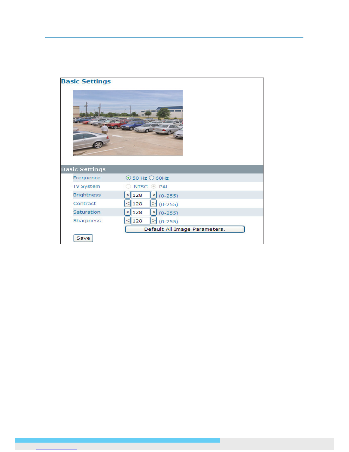
The Basic Setting allows you to specify a frequency and adjust the basic image settings to optimize
your video image.
Frequency: Select an appropriate frequency to reduce the icker on the image. “50 Hz” and
“60 Hz” are provided Frequencies settings will affect the Max. Exposure and Min. Exposure
settings under
Image > Exposure.
TV System: Displays the current video standard: NTSC or PAL. This setting cannot be changed
via web interface.
Brightness: Adjust the image brightness level.
Contrast: Adjust the image contrast level.
Saturation: Adjust the image saturation level.
Sharpness: Adjust the image sharpness level.
Default All Image parameters: Pressing this button will restore all the image settings to the
defaults.
Page 34
3. Web-based Interface
34 User Manual
3.3.5 Smart Encoding
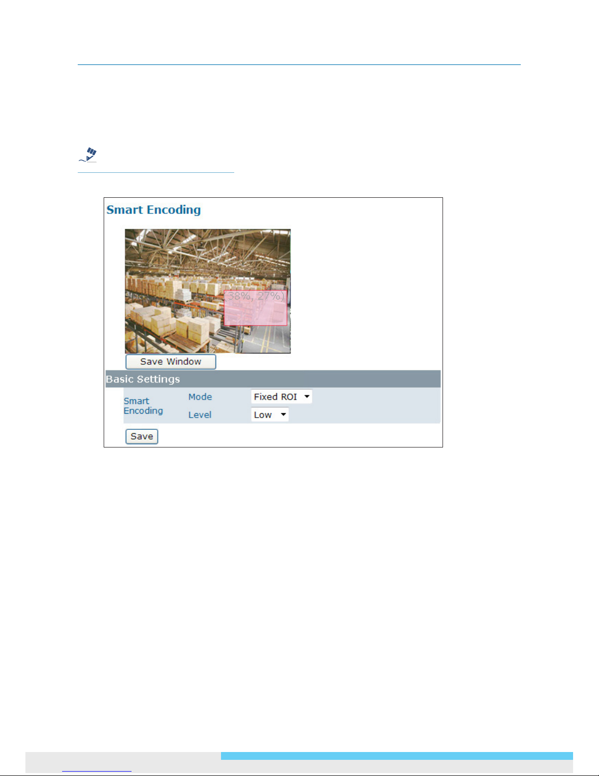
On the Smart Encoding page you can specify a specic region of the video as more important, i.e.,
a region of interest (ROI). When a ROI is specied, the camera will assign a higher number of bits to
the ROI area to deliver better video quality than non-ROI areas.
Note
The Smart Encoding function is only available when H.264 is selected for one of the streams.
Basic Setting
To dene a smart encoding area, click and drag your mouse on the image to dene the region of
interest and click Save Window to save the region. Click anywhere on the image to cancel the
current dened area.
Mode: Select Fixed ROI to enable smart encoding function.
Level: Select a priority level (Low or High) for the ROI.
3.3.6 Smart Focus
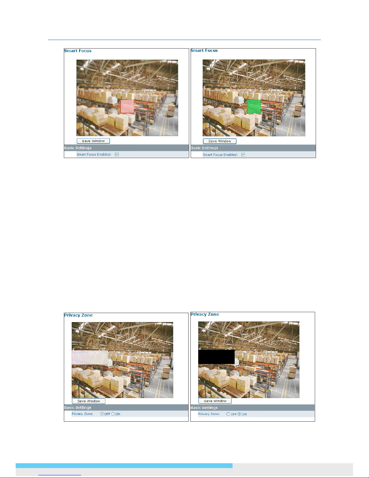
In addition to observing the live view image to see if focus is achieved, you can also enable Smart
Focus to help you verify if focus is locked. If this function is enabled, whenever focus is achieved,
the focus window turns green.
Page 35
3. Web-based Interface
User Manual 35
Basic Settings
To focus on a desired subject using the Smart Focus function:
1. Click on the subject that you want to focus on and then click Save Window.
2. Check the Smart Focus Enabled box. This will turn the smart focus indicator to red.
3. Use the focal length and focus controls to optimize the focus. When focus is achieved, the
indicator turns green.
3.3.7 Privacy Zone
Privacy Zone allows you to mask sensitive areas of the image for privacy protection. If enabled, it
will mask the live view and the recorded video clips/JPEG les.
To turn on the privacy zone function:
1. Click and drag your mouse on the image to dene the region to be masked and then click Save
Window.
2. Select ON to enable Privacy Zone. This will turn the masked area to black.
Page 36
3. Web-based Interface
36 User Manual
3.4 Network
3.4.1 Basic
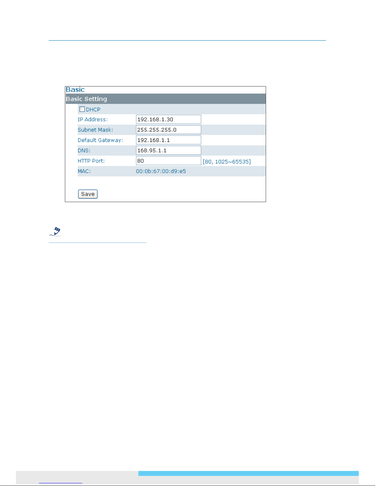
DHCP: If there is a DHCP server on the network and you enable this option, the server will
automatically assign an IP address and related information to the camera.
Note
If there is no DHCP server on your network or you prefer to manually assign an IP address to the
camera, leave the DHCP checkbox blank.
IP Address & Subnet Mask: If the DHCP function is not enabled, you have to assign an IP
address with the subnet mask to the camera.
Default Gateway: Enter the IP address of the gateway if required. Please contact your network
administrator whether you need to set up the gateway.
DNS: Enter the IP address of a DNS server. If you enter a domain name instead of an IP address
in server-related elds, e.g., FTP, SMTP or NTP server, then the camera will need a DNS server
to translate domain names into an IP address that is actually used for communication on the
Internet.
HTTP Port: Use the standard HTTP port number 80 or alternatively specify another port number
between 1025 and 65535.
If you choose to use a non-standard port, and the camera on the LAN is to be accessible from the
Internet, then you must congure your router/rewall to forward incoming HTTP request to that
specied port (via NAPT/port forwarding settings).
MAC: Display the MAC address of the camera. Each camera comes with a unique MAC address,
which is indicated on the product label. It helps you to identify which camera is currently
accessed, particularly when multiple cameras are connected to your network.
Page 37
3. Web-based Interface
User Manual 37
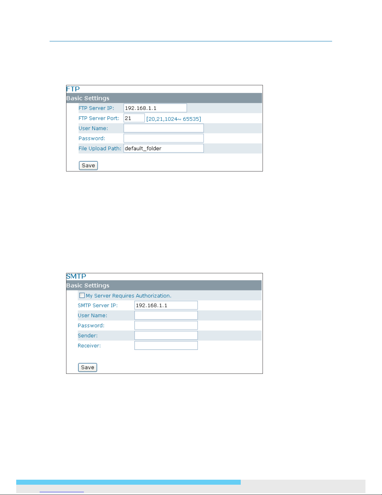
3.3.2 FTP
To allow the camera to upload recorded video clips/JPEG les to an FTP server, you have to specify an
FTP server and congure related settings.
FTP Server IP: Enter the IP address of the FTP server.
FTP Server Port: Enter the port number of the FTP server.
User Name: Enter the user name to logon to the FTP server.
Password: Enter the password to logon to the FTP server.
File Upload Path: Specify the folder which has been created under FTP server root directory.
3.3.3 SMTP
To enable the camera to send you email notications when an alarm is triggered, you need to specify
an SMTP server to send the emails.
My Server Requires Authorization: If your SMTP server requires authorization to send emails,
enable this option.
SMTP Server IP: Enter the IP address of the SMTP server.
User Name: Enter the user name to log on to the SMTP server.
Password: Enter the password to log on to the SMTP server.
Sender: Enter the email address to be shown as the sender of the notication email.
Receiver: Enter the email address to which the notication email is sent.
Page 38
3. Web-based Interface
38 User Manual
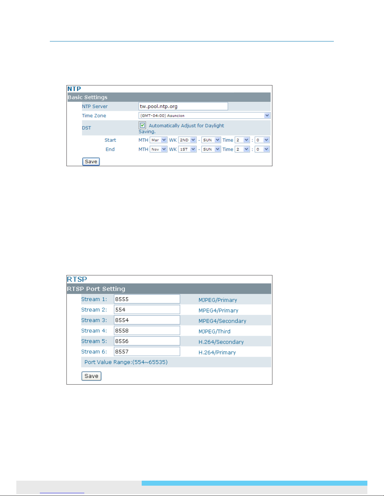
3.3.4 NTP
If you want the camera to synchronize its time clock with an NTP (Network Time Protocol) sever,
congure the NTP server settings here.
NTP Server: Enter the IP address or the domain name of the NTP server to synchronize with.
Time Zone: Select a time zone in which the camera is located.
DST: Tick the Automatically Adjust for Daylight Saving Time Changes check box to apply
the daylight saving time and users are supposed to congure the start/end time period by clicking
the drop-down menus respectively.
3.3.5 RTSP
RTSP is a standard for connecting a client to establish and control streaming data over the web. If
you want to allow third-party devices or software to access video/audio streams from the IP camera
over the network, you must congure the RTSP ports. You can provide up to 6 streams according to
the specic codec mode with different RTSP port.
To use an RTSP player to access the camera’s streams, you have to use correct RTSP URL to request
the streams. Refer to the table below for RTSP URLs:
Page 39
3. Web-based Interface
User Manual 39
Stream URL
MJPEG Primary rtsp://192.168.1.30:8555/mjpeg
MJPEG Third rtsp://192.168.1.30:8558/mjpeg
H.264 Primary rtsp://192.168.1.30:8557/h264
H.264 Secondary rtsp://192.168.1.30:8556/h264
MPEG4 Primary rtsp://192.168.1.30:554/mpeg4
MPEG4 Secondary rtsp://192.168.1.30:8554/mpeg4
*Replace the IP address and the port number with the camera’s settings if otherwise congured.
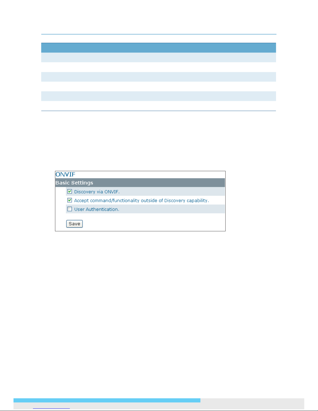
3.3.6 ONVIF
ONVIF is a standard that ensures interoperability between IP-based physical security products
regardless of the manufacturers. This camera is ONVIF compliant and you can congure whether the
camera can be found by other ONVIF compliant products and the related settings.
Basic Settings
Discovery via ONVIF: Check the box if you want the camera to be found by other ONVIF
compliant devices in a network, e.g., an ONVIF compliant NVR.
Accept command/functionality outside of Discovery capability: If checked, the camera
is allowed to accept commands from ONVIF compliant device thus changing the camera’s
functionality.
User Authentication: If an ONVIF compliant device needs authentication for communication,
enable this option.
Page 40
3. Web-based Interface
40 User Manual
3.4 System
3.4.1 Date and Time
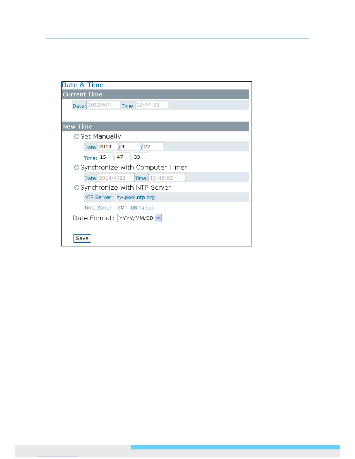
Current Time
Displays the current date and time of the camera. Date and time will be updated after you congure
new settings in the New Time section and click Save to apply the settings.
New Time
You can set the camera time by one of the following methods:
Set Manually: Manually enter the camera’s date and time settings in the given elds.
Synchronize with Computer Timer: Use this option to synchronize the camera’s date and time
with the computer timer.
Synchronize with NTP Server: Use this option to synchronize the camera’s date and time with
an NTP (Network Time Protocol) server, which can be congured under Network > NTP.
Date Format: Allows you to specify a desired date format.
Page 41
3. Web-based Interface
User Manual 41
3.4.2 Time Stamp
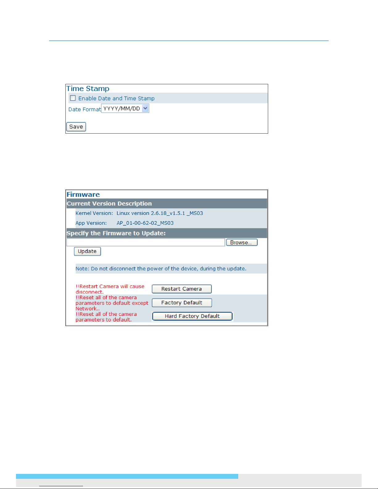
The Time Stamp function allows you to overlay the date and time stamp on the video. When
enabled, the recorded video will be displayed with the date and the time.
Enable Date and Time Stamp: Check this box to enable the date and time stamp on images/
video clips; to disable this function, uncheck the box.
Date Format: Select the desired date format for the time stamp.
3.4.3 Firmware
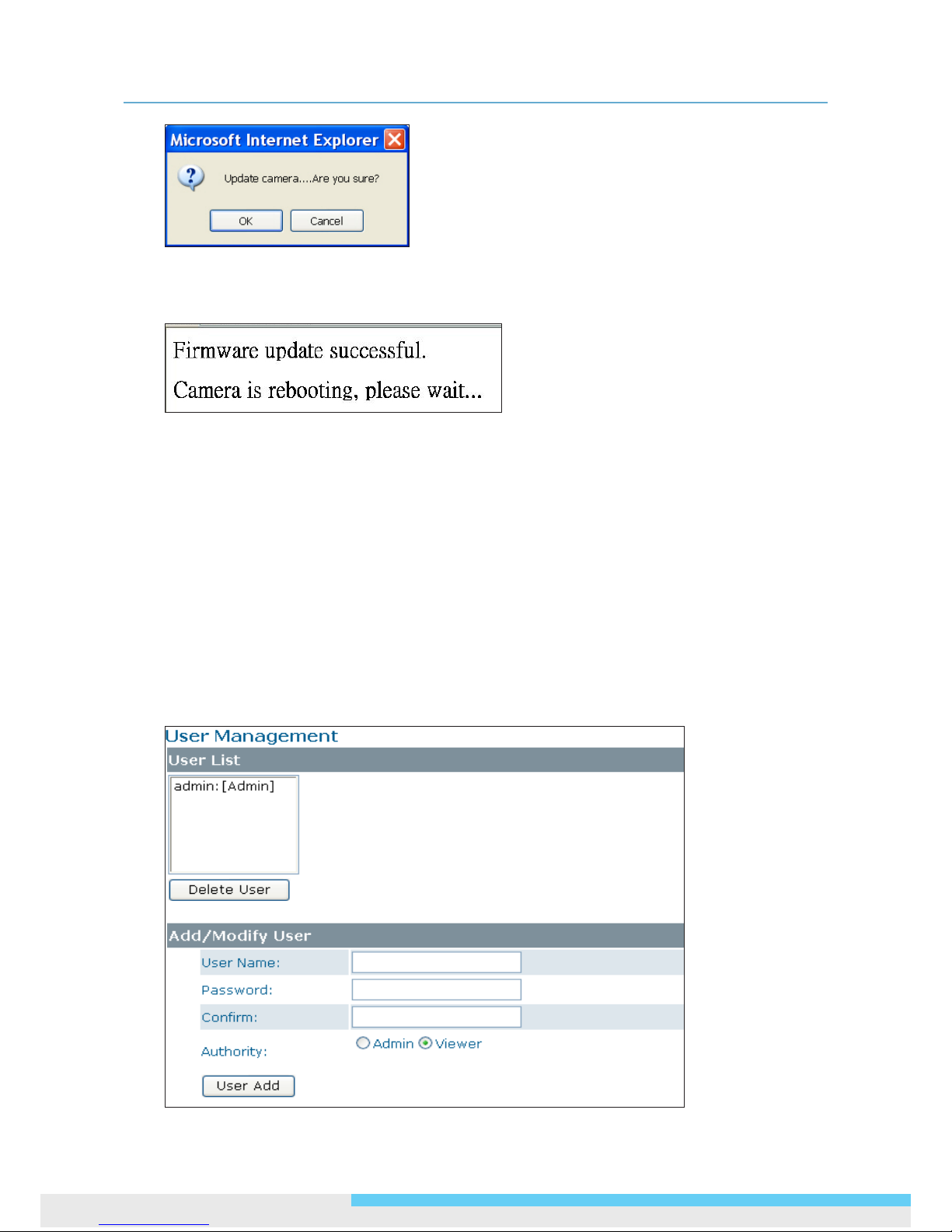
Current Version Description: Displays the current version of the rmware.
Specify the Firmware to Update: This function is designed to update the rmware of the camera.
To perform the rmware upgrade, follow these parameters:
Keep the network connected during the update process.
DO NOT turn off or restart the camera during the rmware update process.
To update the rmware:
1. Click the Browse button to locate the rmware le.
2. Click the Update button to start update.
3. When prompted, click OK to proceed.
Page 42
3. Web-based Interface
42 User Manual
1. Wait about 20~60 seconds until the le is successfully updated. Once the update is completed,
the browser will show a message reads “Firmware update successful”. Then it will take 60 seconds
to restart the camera.
2. The utility will automatically go back to live view screen after rmware has been updated
successfully.
You can also perform these tasks on the Firmware page:
Restart camera: Restart the camera. This will cause all streams to disconnect.
Factory Default: Reset all of the camera settings to the defaults, except network settings. After
you conrm to reset, the camera will reset and restart automatically. When complete, you will
return to the live view page.
Hardware Factory Default: Reset all of the camera parameters to the defaults, including the
network settings.
3.4.4 User Management
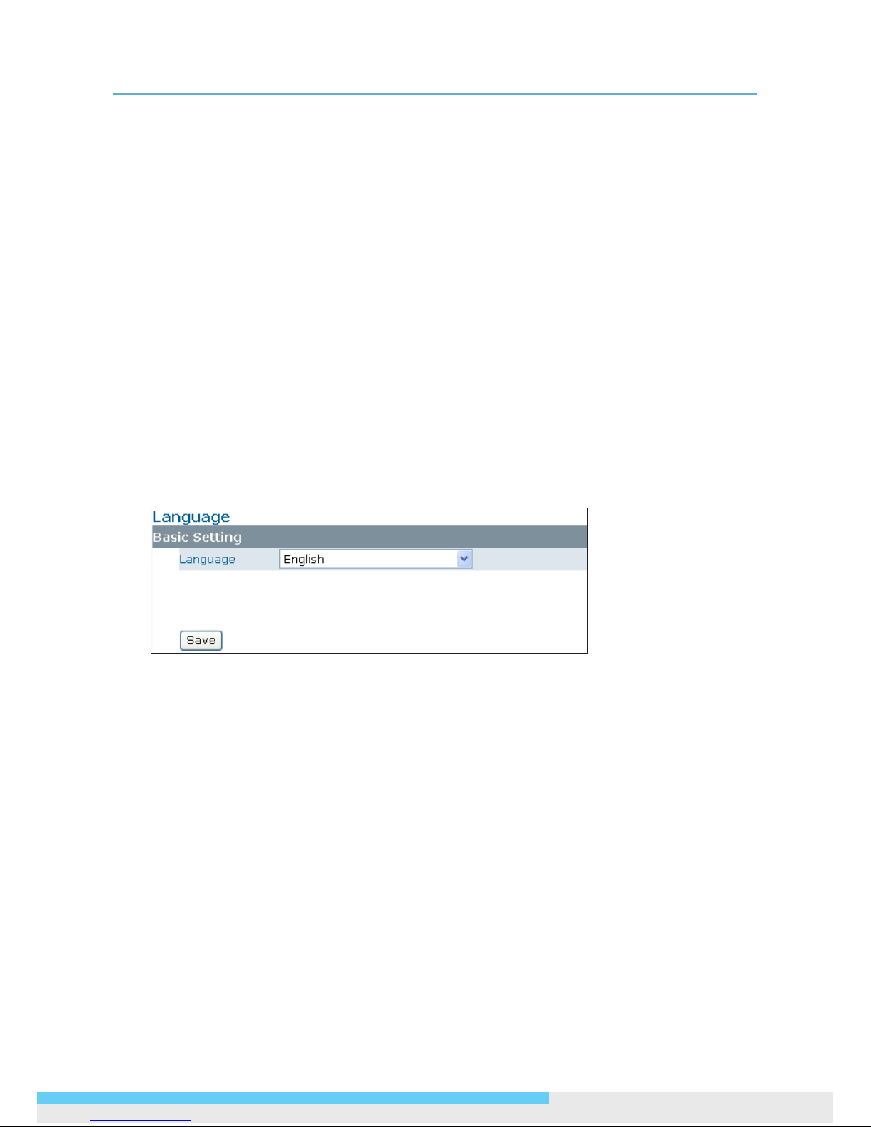
The User Management page allows you to manage user accounts and access privileges.
Page 43
3. Web-based Interface
User Manual 43
User List
Displays the list of current user accounts of the camera. To delete a user account, select the
unwanted user account from the list and then click Delete User.
Add/Modify User
You can add a new user or modify current user’s account or authority.
To add a new user, enter the user name and password and specify the authority. Then click User
Add to add a user.
To modify the password of the existing user, enter the user name and modify the password.
Two types of account can be specied:
• Admin (Administrator): Can access all camera functions, pages and make congurations.
• Viewer (Guest): Can only access the live view page and take snapshots.
3.4.5 Language
The Language drop-menu allows you to change the language of the web interface. Supported
languages include English, Spanish, Italian, Simplied Chinese and Traditional Chinese. Click Save to
apply the language setting, and the browser will automatically refresh to reect the change.
3.4.6 Log
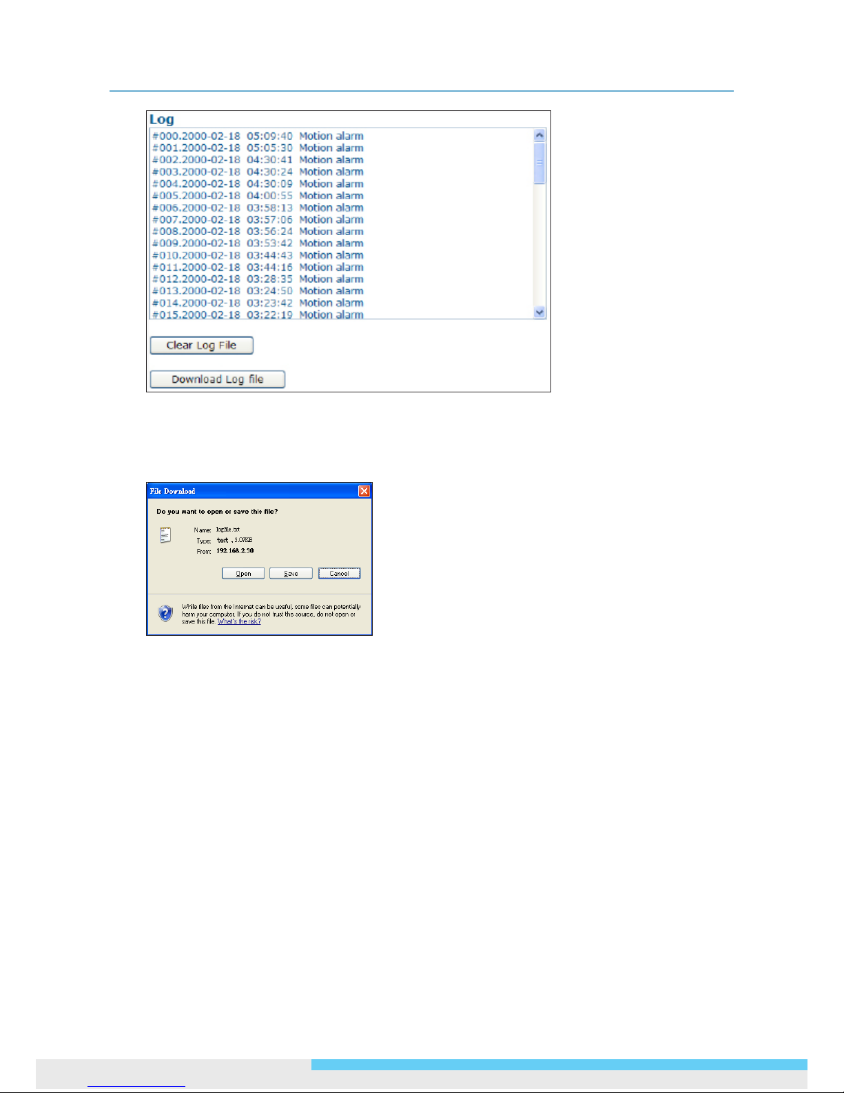
This page displays detailed information about the camera’s operations and activities, including all the
login and alarm records.
Page 44
3. Web-based Interface
44 User Manual
Clear Log File: Click the button to clear the log cache.
Download Log File: Click the button to save the current log into a text le. When a dialog
window shows up, click the Save button to locate the directory where the logle.txt is to be
stored.
Page 45
3. Web-based Interface
User Manual 45
3.4.7 Audio
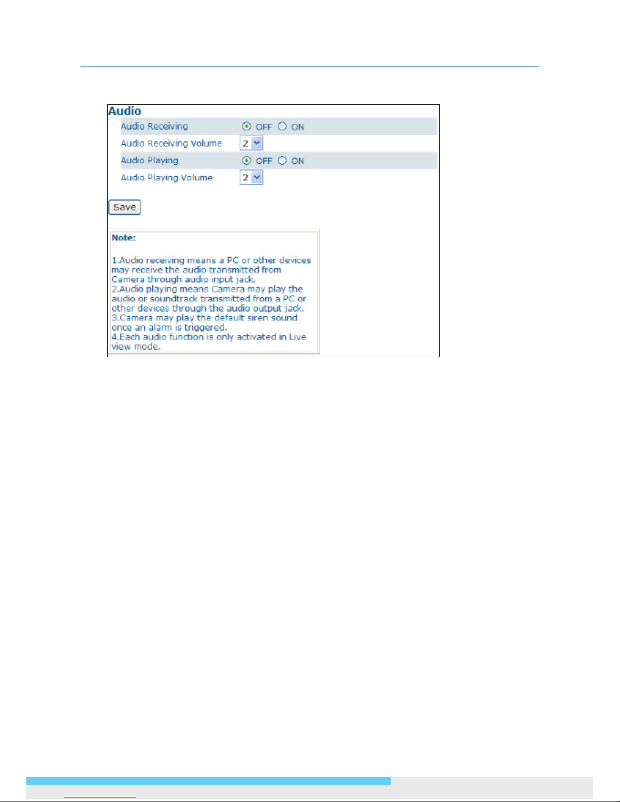
Audio Receiving: If a microphone is connected to the camera, you can select ON to allow the
camera to record the audio and transmit to your PC. This enables the camera to pick up sounds in
the background.
Audio Receiving Volume: Allows you to adjust the audio recording volume of the camera
ranging from 1 to 4.
Audio Playing: If a speaker is connected to the camera, you can select ON to allow the camera
to play the audio transmitted from your PC. This enables you to speak to the person(s) around
the camera.
Audio Playing Volume: Allows you to adjust the audio playing volume of the camera ranging
from 1 to 4.
Using the two-way audio function
Note that the two-way audio function is only active in the live view page using the web browser.
To use the two-way audio function:
1. Make sure a speaker is connected to the Audio Out port and a microphone is connected to the
Audio In port of the camera.
2. Enter System > Audio and enable both the Audio Receiving and Audio Playing functions.
Then adjust the audio volume to the desired level.
3. To access the two-way audio streams:
4. Make sure your computer is connected to a microphone and speaker. Enter the live view page of
the web-based utility.
5. Speak into the microphone and the person(s) around the camera should hear your voice.
6. When people around the camera are talking to you, you should hear them from the speaker that
is connected to the computer.
Page 46
3. Web-based Interface
46 User Manual
3.5 Event
When an event occurs, it triggers an alarm and the camera will take a pre-dened action, e.g.,
sending a recorded video clip or JPEG les to a designated server. With this camera, an event can
be triggered by external alarm devices or the camera’s detection mechanism, including motion, blur,
audio and Ethernet detection.
Note
1. When there is more than one recording to be carried out at the same time, the scheduled video
recording takes top priority, followed by the recording triggered by an Ethernet disconnection and
lastly the recording triggered by other events.
2. Only one event will be handled at a time. If an event is already triggered, other event will be
logged to the system but no action will be taken.
3.5.1 Motion Detection
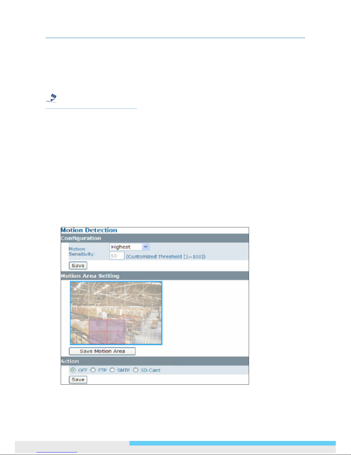
When the Motion Detection is enabled, the camera detects motion under a pre-specied condition
within a designated area. When motion is detected, the camera will generate an alarm and then take
a specied action.
Note that to use the motion detection function, the following two conditions must be met:
1. You must select MJPEG codec for one of the streams to enable the live view.
2. You must select H.264 or MPEG4 codec for one of the streams to process the motion detection.
Page 47
3. Web-based Interface
User Manual 47
Conguration
Motion Sensitivity: Specify the sensitivity to moving objects before the camera triggers an
alarm. The higher the sensitivity, the slighter the movement is required to set off an alarm.
You can alternatively select User Dene and enter a value from 1 to 100 in the Customized
Threshold eld. When the motion within a specied area exceeds the threshold, an alarm will be
triggered.
Select OFF to disable the motion detection
Motion Area Setting
Motion area setting: Click target squares displayed on the screen to dene detection areas;
once congured, click Save Motion Area to save settings.
Action
Specify the action to be taken when an alarm is triggered upon motion detection:
OFF: No action will be taken, but an alarm will be logged.
FTP: Recorded video clips/JPEG les will be uploaded to the FTP server when alarm is triggered.
SMTP: Notication email with the recorded JPEG les attached will be sent to the SMTP server.
SD Card: Recorded video clips will be saved to the SD card when the alarm is triggered.
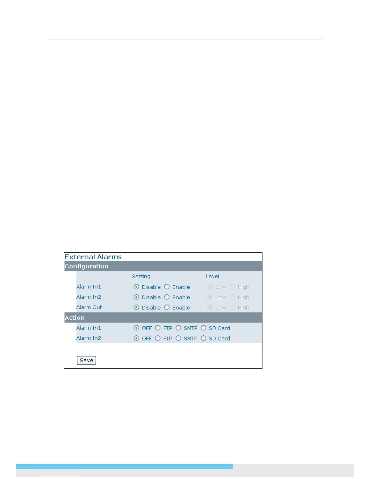
3.5.2 External Alarms
If external alarm devices, e.g., sensors and alarms, are connected to the camera’s alarm input/
output, the following settings must be made:
Conguration
Setting: Enable the Alarm I/O that is connected with the respective external alarm device.
Level: Set the (electricity) current as low or high to dene the active state.
Page 48
3. Web-based Interface
48 User Manual
Action
Specify the action to be taken when external alarm is triggered:
OFF: No action will be taken, but an alarm will be logged.
FTP: Recorded video clips/JPEG les will be uploaded to the FTP server when alarm is triggered.
SMTP: Notication email with the recorded JPEG les attached will be sent to the SMTP server.
SD Card: Recorded video clips will be saved to the SD card when the alarm is triggered.
Note
To perform a video recording, you must select MJPEG codec for one of the streams.
3.5.3 Face Detection
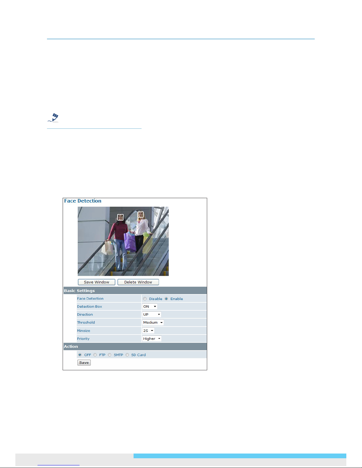
With the Face Detection enabled, one or multiple square frames will cover the faces detected in
the scene. You can specify a particular area by clicking and dragging your mouse, and then click the
Save Window button. People’s faces appearing within the area will be detected. Click the Delete
Window button followed by clicking Save to remove the dened region.
Basic Settings
Face Detection: Enable/Disable face detection. When the selected radio button is changed and
the Save button is clicked, the camera may take around 25 seconds to restart while the web
displaying the status being loading.
Detection Box: Select ON to show square frames on the screen for the detected faces.
Page 49
3. Web-based Interface
User Manual 49
Direction: Select the orientation of faces in the video stream. UP means the top of the face
is generally in the up direction. The orientation may need to be adjusted when the camera is
installed on its side or at an angle.
Threshold: Select a face detection acceptance tolerance (High/Medium/Low).
Minsize: Select the minimum size of the detection box. Options include 20, 25, 32 and 40;
smaller value means smaller faces in the distance can be detected.
Priority: Select whether face regions have higher or lower encoding priority when the Advanced
Settings ROI feature is applied.
Action
Select the radio buttons for actions in response to the pictures saved to FTP server, SMTP server or
SD card if a face detection alarm is triggered. OFF is set by default.
OFF: No action will be taken (but an alarm is logged).
FTP: Recorded AVI/JPEG les will be uploaded to an FTP server when the alarm is triggered.
SMTP: Notication e-mail attached with the recorded JPEG les will be sent to a SMTP server.
SD Card: Recorded AVI/JPEG les will be saved to the SD card when the alarm is triggered.
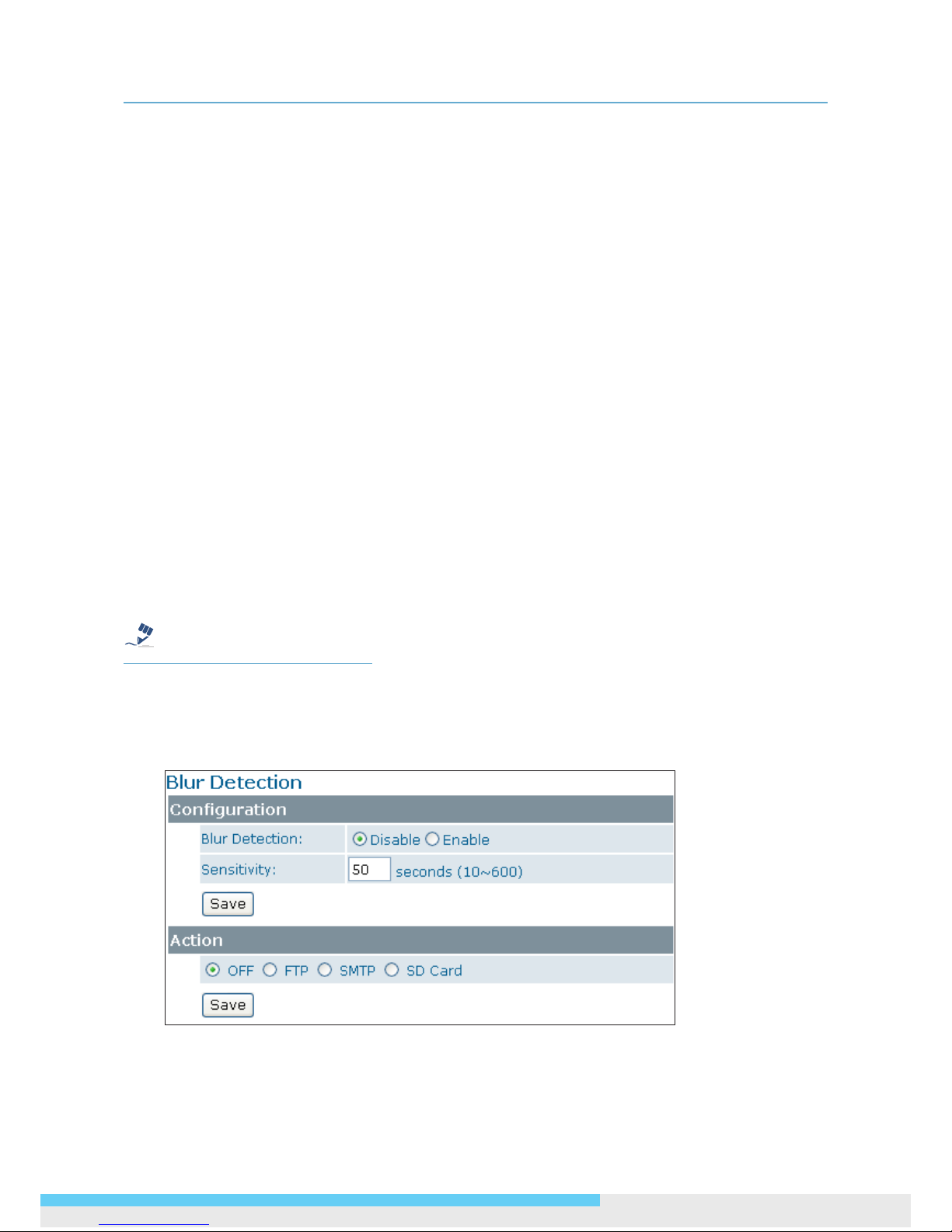
3.5.4 Blur Detection
With the Blur Detection enabled, when the camera detects incidents that make video image blur,
e.g. redirection, blocking or defocusing, the camera will generate an alarm and then take a specied
action.
Note
Note that to use the blur detection function, the following two conditions must be met:
1. You must select MJPEG codec for one of the streams to enable the live view.
2. You must select H.264 or MPEG4 codec for one of the streams to process the motion detection.
Conguration
Blur Detection: Select Enable to enable Blur Detection; select Disable to disable this function.
Page 50
3. Web-based Interface
50 User Manual
Sensitivity: You can alternatively customize the camera’s sensitivity to a blur. The camera will
judge whether it has been tampered based on the sensitivity threshold specied.
Action
OFF: No action will be taken, but an alarm will be logged.
FTP: Recorded video clips/JPEG les will be uploaded to the FTP server when alarm is triggered.
SMTP: Notication email with the recorded JPEG les attached will be sent to the SMTP server.
SD Card: Recorded video clips will be saved to the SD card when the alarm is triggered.
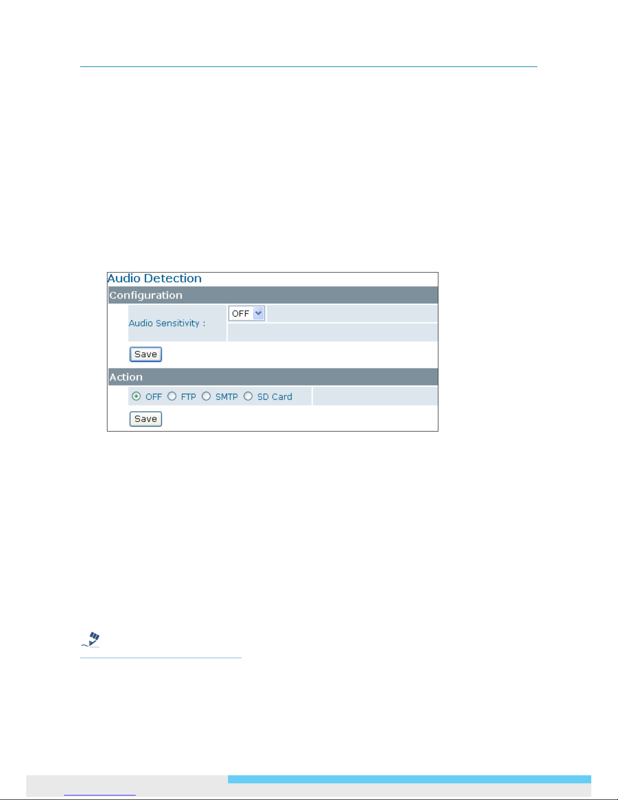
3.5.5 Audio Detection
With the Audio Detection enabled, when the camera detects any sound, the camera will generate
an alarm and then take a specied action.
Conguration
Audio Sensitivity: Specify the camera’s sensitivity level to the audio signal. The higher the
sensitivity, the lower the volume is required to set off an alarm.
When set to OFF, the audio detection is disabled.
Action
Specify the action to be taken when an alarm is triggered upon audio detection:
OFF: No action will be taken, but an alarm will be logged.
FTP: Recorded video clip will be uploaded to the FTP server when the alarm is triggered.
SMTP: A notication email attached with the recorded video clip will be sent to the SMTP server.
SD Card: Recorded video clip will be saved to the SD card when the alarm is triggered.
Note
To perform a video recording, you must select MJPEG codec for one of the streams.
Page 51
3. Web-based Interface
User Manual 51
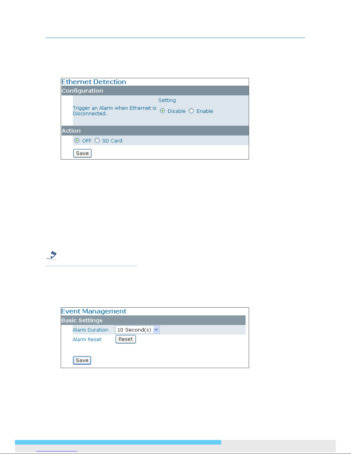
3.5.6 Ethernet Detection
With Ethernet detection enabled, when the camera detects an Ethernet disconnection, the camera
will generate an alarm and then take a specied action.
Conguration
Trigger an Alarm When Ethernet is Disconnected: Select whether to disable/enable this
function.
Action
Specify the action to be taken when an alarm is triggered upon audio detection:
OFF: No action will be taken, but an alarm will be logged.
SD Card: Recorded video clips will be saved to the SD card in AVI format when the alarm is
triggered.
Note
Regardless of your settings in Recording > SD card, when an Ethernet disconnection is triggered,
the video clip recording will always be saved in AVI format.
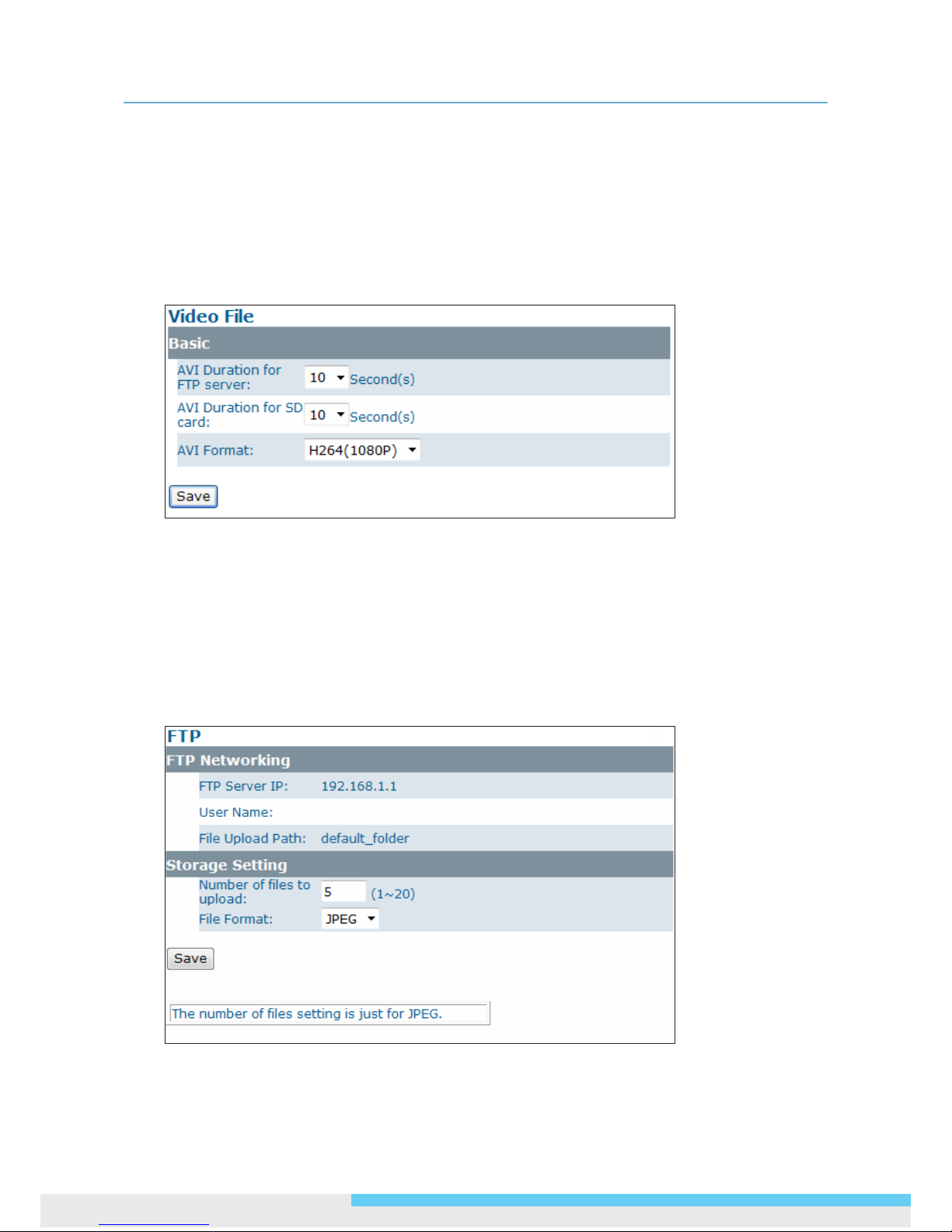
3.5.7 Event Management
Basic Setting
Alarm Duration: Specify the duration of the alarm when an event is triggered.
Alarm Reset: Use this button to stop the current alarm and to restart event detection again.
Page 52
3. Web-based Interface
52 User Manual
3.6 Recording
Recording allows you to congure recording-related settings and schedule recording. The defaults are
listed in the table below:
3.6.1 Settings – Video File
Congure the duration and format of video to be recorded when an alarm is triggered.
Basic Settings
AVI Duration for FTP Server: Select recorded video duration in seconds for the FTP server.
AVI Duration for SD Card: Select recorded video duration in seconds for the SD card.
AVI Format: Select a desired video format. Available formats depend on the primary and the
secondary streaming codec/resolution settings.
3.6.2 Settings – FTP
Page 53
3. Web-based Interface
User Manual 53
FTP Networking
Displays the current FTP settings, which are specied via Network > FTP.
Storage Setting
Number of les to upload: Enter the number of JPEG les to be uploaded to the FTP per event.
File Format: Select the format in which to upload the recorded video le to the FTP server when
an event has been triggered.
• JPEG les: The camera will record specied number of JPEG les and upload to the FTP
server.
• AVI les: The camera will record AVI les and upload to the FTP sever. For the duration and
AVI format, see Recording > Setting > Video File.
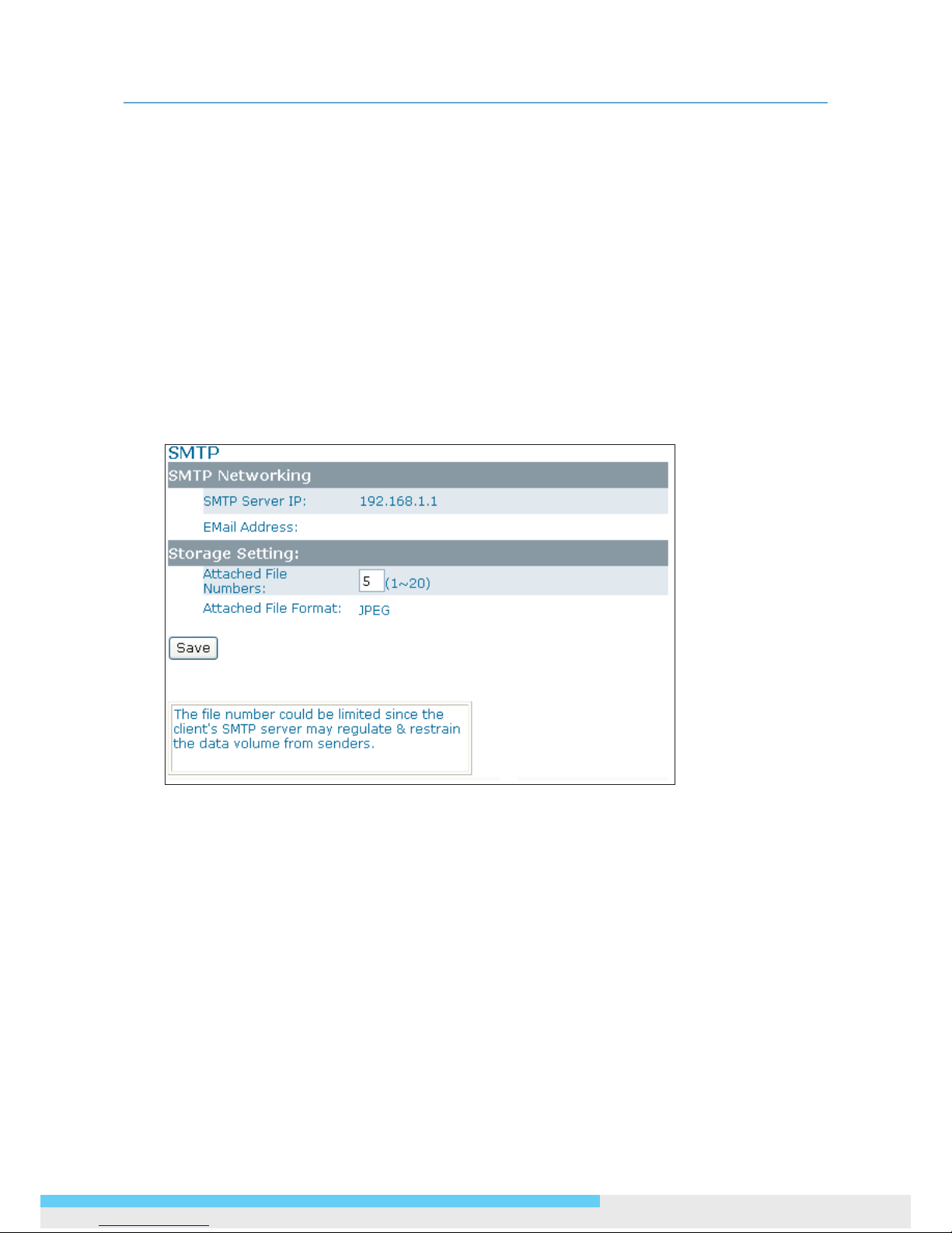
3.6.3 Settings – SMTP
SMTP Networking
Displays the current SMTP settings, which are specied via Network > SMTP.
Storage Setting
Attached File Numbers: Enter the number of JPEG images that will be attached to the
notication email. Set a lower number if SMTP server has an email size limit.
Attached File Format: In JPEG format always.
Page 54
3. Web-based Interface
54 User Manual
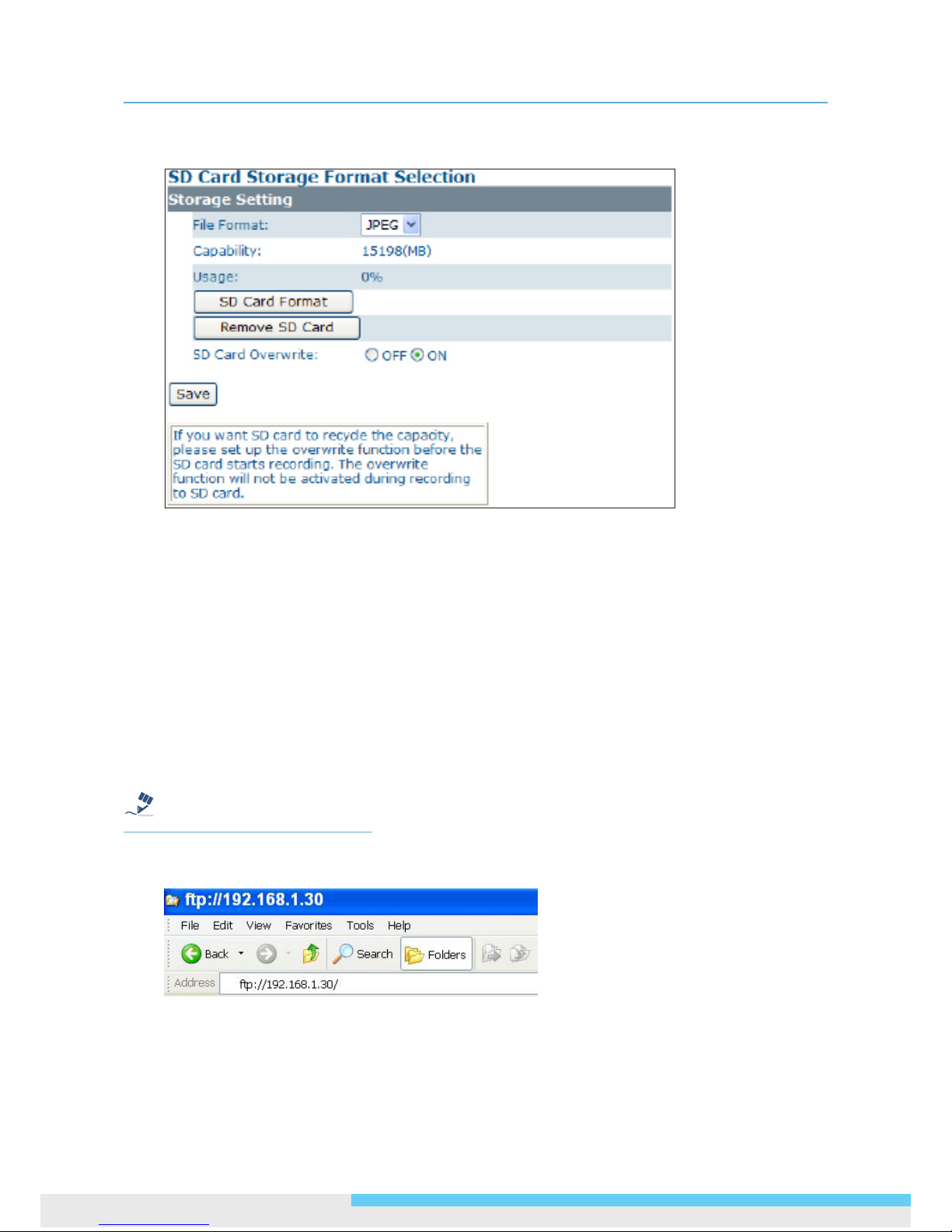
3.6.4 SD Card Storage Format Selection
Storage Setting
File Format: Specify the format of the video/picture to be saved to the SD card when an event is
triggered.
Capacity/Usage: Shows the card capacity and the space usage percentage.
SD Card Format: Use this button to format the SD card. This option is not available if an SD card
has not been inserted in the camera.
Remove SD Card: Click this button before safely removing the SD card. This option is not
available if an SD card has not been inserted in the camera.
SD Card Overwrite: Select ON to enable overwriting once the storage is full.
Accessing SD Card
Note
Users can access the SD card via the FTP service by entering the FTP address (ftp://192.168.1.30
by default) in the URL eld of the web browser.
Then an FTP login window shows up asking for login ID and password. After lling in the login ID and
password elds (defaults are admin and 1234 respectively), you can see the the FTP directory with
successful login.
Page 55

3. Web-based Interface
User Manual 55
Besides, users can also just launch the Windows Explorer to access SD card. The same, users are
supposed to enter the FTP address (ftp://192.168.1.30 by default) in the address eld and nish
login process. Then you can directly get into the directory.
3.6.5 Period Setting
The Period Setting allows you to schedule video recordings at specied times. Set the automatic
recording times by selecting the desired weekday and the period of time. Up to 7 scheduled
recordings can be set. Check Save to SD Card should you wish to save the recorded video clips to
the SD card.
Note
The scheduled recording always demands higher priority than the alarm-based recording. When a
scheduled recording is proceeding, the alarm-based recording will be disabled but the alarms will be
logged.
Page 56
4. VLC Player for RTSP Streaming Access
56 User Manual
4. VLC Player for RTSP
Streaming Access
Note
This information is provided for convenience only. We will not provide support for the installation
or use of VLC software.
The IP addresses used in the document are the default URLs and are provided for example
purposes only. You will need to use an IP address that is appropriate for your network.
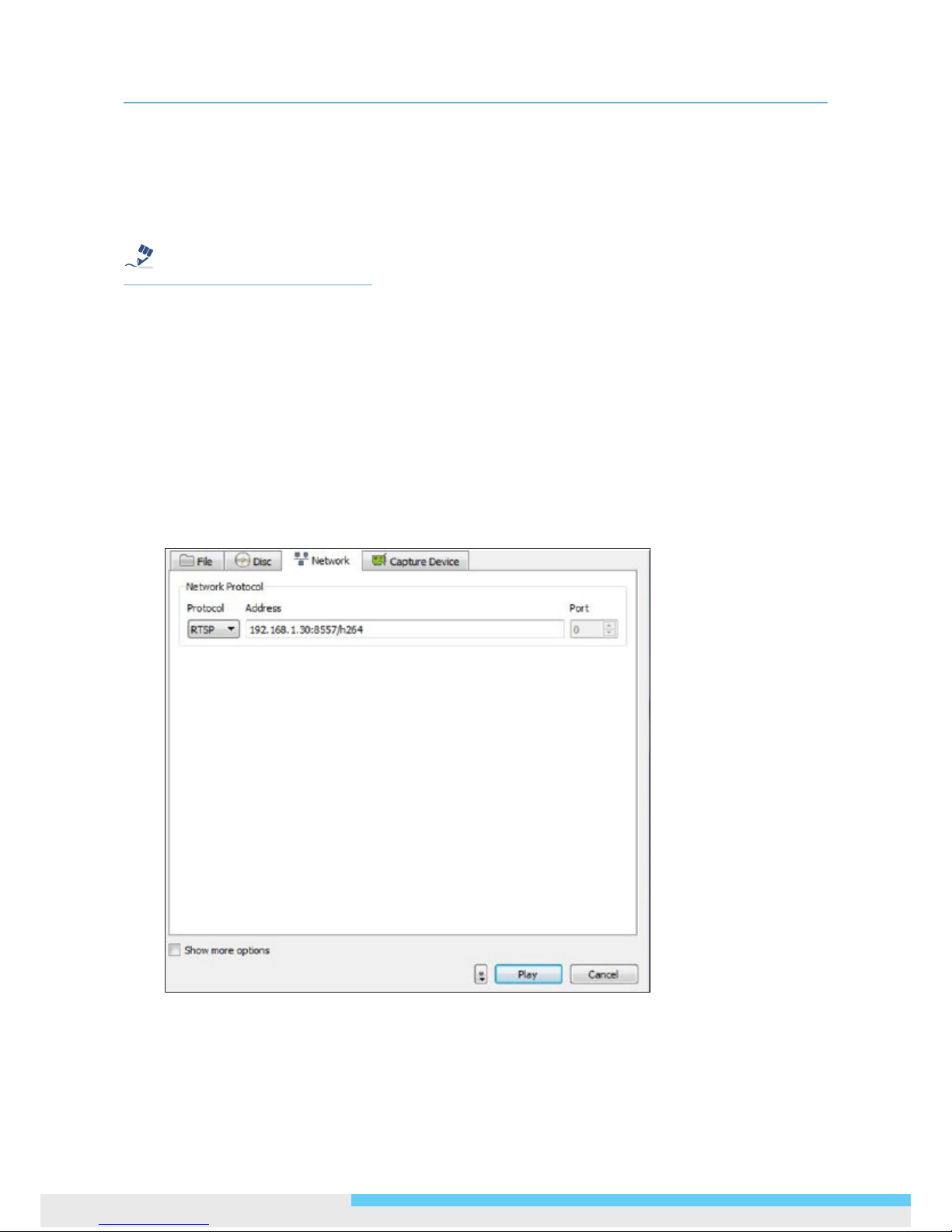
To use VLC player to view RTSP streaming, follow these steps to proceed:
1. Download and install VLC Player (version 1.0.5) from http://www.videolan.org/vlc.
2. Launch VLC Player.
3. Click Media _Open Network Stream.
4. On the Network tab, choose RTSP from the Protocol menu.
5. In the Address eld enter the IP address of the stream that you want to view.
Page 57

4. VLC Player for RTSP Streaming Access
User Manual 57
The table below lists default URLs.
Stream URL
MJPEG Primary rtsp://192.168.1.30:8555/mjpeg
MJPEG Third rtsp://192.168.1.30:8558/mjpeg
H.264 Primary rtsp://192.168.1.30:8557/h264
H.264 Secondary rtsp://192.168.1.30:8556/h264
MPEG4 Primary rtsp://192.168.1.30/mpeg4
MPEG4 Secondary rtsp://192.168.1.30:8554/mpeg4
6. Click Play and you will see the image streaming.
 Loading...