

Page 1

MeshLinx
MWI-5000 User Guide
Version 1.06
MeshLinx MWI-5000 User Guide © 2006, MeshLinx Inc. All rights reserved.
The information contained in this document, including design, text, and graphics is the property of MeshLinx,
Inc. Time-Based Auto-Recognition (TBAR) is a registered trademark of MeshLinx, Inc. Other trademarks
are the proper of the entities referenced herein.
MeshLinx, Inc.
Richardson, TX
MESHLINX CONFIDENTIAL
Page 2

MeshLinx MWI-5000 User Guide
Table of Contents
1.0 Scope....................................................................................................................... 3
1.1 Reference Documents .................................................................................................. 3
1.2 Guide Content .............................................................................................................. 4
2.0 Introduction............................................................................................................ 4
2.1 MWI-5000 System Features........................................................................................ 4
3.0 Installation ............................................................................................................. 5
3.1 Finding the Correct Site.............................................................................................. 5
3.1.1 SDMA Capacity vs. Range Mode........................................................................................... 5
3.1.2 User Distribution.................................................................................................................... 5
3.1.3 Avoiding Reflective Surfaces................................................................................................. 5
3.1.4 Minimizing Interference.........................................................................................................5
3.1.5 Obstacles................................................................................................................................. 6
3.2 Power and Network Connections ............................................................................... 6
3.2.1 Serial Port............................................................................................................................... 6
3.2.2 Power-over-Ethernet Connection ........................................................................................... 7
3.2.3 Using the External Power Supply........................................................................................... 7
3.2.4 Changing the Factory Default MAC Address......................................................................... 7
4.0 Configuration and Operation................................................................................ 8
4.1 Default Settings ............................................................................................................ 8
4.2 Command Line Interface .......................................................................................... 13
4.2.1 Command Conventions ........................................................................................................ 13
4.2.2 Getting Started...................................................................................................................... 13
4.2.3 Commands............................................................................................................................ 13
4.2.4 Firmware Update.................................................................................................................. 37
4.3 Web Interface............................................................................................................. 39
4.3.1 The Status Page .................................................................................................................... 41
4.3.2 Configure Menu.................................................................................................................... 44
4.3.3 Configure - System :............................................................................................................. 45
4.3.4 Configure - SSID/Security/VLAN : ..................................................................................... 47
4.3.5 Configure - Filter :................................................................................................................ 48
4.3.6 Configure - Password :......................................................................................................... 49
4.3.7 Configure - TCP/IP :............................................................................................................. 50
4.3.8 Configure – DHCP :............................................................................................................. 51
4.3.9 Configure – HTTP :..............................................................................................................52
4.3.10 Configure – RADIUS : .................................................................................................... 53
4.3.11 Configure - SNMP........................................................................................................... 54
4.3.12 Configure – Ethernet :...................................................................................................... 55
4.3.13 Configure - Wireless Interfaces : ..................................................................................... 56
4.3.14 Configure – Basic Settings: ............................................................................................. 56
4.3.15 Configure – Advance Settings : ....................................................................................... 57
4.3.16 Configure- Spectrum Management:................................................................................. 58
4.3.17 Configure – Backhaul Settings : ...................................................................................... 60
4.3.18 Configure Listen and Learn : ........................................................................................... 61
MESHLINX CONFIDENTIAL 2
Page 3

MeshLinx MWI-5000 User Guide
4.3.19 Configure – QoS :............................................................................................................ 62
4.3.20 Configure DFS :............................................................................................................... 68
4.3.21 Configure RRM : ............................................................................................................. 69
4.3.22 Configure TPC :............................................................................................................... 70
4.3.23 Configure Date and Time : .............................................................................................. 72
4.3.24 Commands - Configurations :.......................................................................................... 73
4.3.25 Statistics Window ............................................................................................................ 76
4.3.26 The Support Page............................................................................................................. 80
5.0 Trouble Reporting................................................................................................ 81
6.0 Specifications ....................................................................................................... 81
6.1 Reference Design........................................................................................................ 82
7.0 Configurable Parameters..................................................................................... 83
7.1 Wireless Sectors (interfaces)..................................................................................... 83
7.1.1 MAC Address....................................................................................................................... 83
7.1.2 Mode..................................................................................................................................... 84
7.1.3 Channel................................................................................................................................. 85
7.1.4 Self-CTS (11G Protection Mode)......................................................................................... 85
7.1.5 Transmit Power..................................................................................................................... 86
7.1.6 Automatic Transmit Power Adjustment............................................................................... 86
7.1.7 Digital Pre-distortion............................................................................................................ 86
7.1.8 Sensitivity............................................................................................................................. 87
7.1.9 Maximum Data Rate............................................................................................................. 87
7.1.10 Diversity .......................................................................................................................... 88
7.1.11 Header (preamble) ........................................................................................................... 88
7.1.12 Beacon Interval................................................................................................................ 89
7.1.13 Fragmentation.................................................................................................................. 89
7.1.14 RTS/CTS .......................................................................................................................... 89
8.0 Glossary................................................................................................................ 90
1.0 Scope
This User guide is the primary document for installation and operation of the
System. It provides basic information and product background for system
integrators and designers evaluating one or more of MeshLinx’s technologies
related to the MWI-5000 Spatial Division Multiple Access (SDMA).
1.1 Reference Documents
Programmer’s Reference (MeshLinx P/N 960320-9001): Includes the API
Reference and System Software information for system integrators and system
designers.
MWI-5000 System Command Line Interface (CLI) Reference (MeshLinx P/N
730180-9001): Includes the full list of advanced commands available through the
CLI for advanced users. It contains many commands not accessible via the web
interface.
MESHLINX CONFIDENTIAL 3
Page 4

MeshLinx MWI-5000 User Guide
1.2 Guide Content
This guide contains tabletop installation instructions including:
• Selecting a site
• Connecting to power and the network
• Installing software and powering up the unit
• Changing the factory default MAC address
• Configuration
• Focusing on the web interface, including a summary of Command Line
Interface (CLI) commands
• Managing the MWI-5000 System via the web interface and the CLI
• Troubleshooting
• Specifications
• Glossary of important terms
2.0 Introduction
The MWI-5000 System is designed to help in the testing and evaluation of the
MeshLinx MWI-5000, a tri-channel IEEE 802.11 MAC/Base Band processor. The
system is a complete operating three channel Access Point that can be configured
as a three sector SDMA AP or a dual-band (2.4 and 5GHz) AP with a monitoring
channel. MWI-5000 System Features
The MWI-5000 System can operate three concurrent channels of IEEE 802.11b, g
or a (or any combination) using the three sector SDMA antenna provided.
Alternately, omni-directional antennas can be used for a dual-band AP with
continuous monitoring. In either mode, the MWI-5000 Listen+Learn protocol
simplifies the installation and management of one or more MWI-5000 System
access points by automatically configuring the channel and transmit power settings
for the AP. When enabled, the MWI-5000 Listen+Learn protocol monitors RF
activity in the environment when the access point is powered on. This monitoring
process discovers other access points (both MWI-5000 and non-MWI-5000 access
points) in the vicinity of the MWI-5000 System. The data gathered during the
monitoring process is then used to select channel and transmit-power settings that
minimize interference between the MWI-5000 System and other access points,
resulting in increased performance of wireless data transfer through the MWI-5000
System. When multiple MWI-5000 Systems are connected to the same wired
network, the MWI-5000 Systems work cooperatively to determine the channel and
transmit-power settings that provide optimal wireless data transfer performance for
the wireless network.
MESHLINX CONFIDENTIAL 4
Page 5

MeshLinx MWI-5000 User Guide
3.0 Installation
This section contains information about proper installation of the system to
maximize performance. Following these guidelines will enable the best possible
results for the evaluation.
3.1 Finding the Correct Site
One of the major advantages of the MWI-5000 System is that it greatly simplifies
the site selection process. However, there are some guidelines that should be
followed to optimize performance.
3.1.1 SDMA Capacity vs. Range Mode
Although the simultaneous use of three channels is the main benefit of the
sectorized antenna SDMA, it is also possible to increase range by setting all three
sectors on the same channel. For maximum capacity the three sectors must be set to
channel 1, channel 6 and channel 11.
3.1.2 User Distribution
As a general rule, it is a good idea to locate the MWI-5000 System in the center of
the distribution of users, but this assumes a fairly even distribution.
Because configuration (and reconfiguration) of the sectors is so simple, and
MeshLinx’s Listen+Learn software can help with interference mitigation and load
balancing, this consideration for site selection is not very critical.
3.1.3 Avoiding Reflective Surfaces
The most important concern in the selection of a mounting site is the avoidance of
walls, ceilings, floors and metal surfaces close to the MWI-5000 System. These
surfaces tend to reflect radio frequency (RF) signals and, if they are close, reflect
strong signals. This results in a reduction of SDMA effectiveness, which means
more interference and therefore poorer signal quality.
Wherever possible, keep the MWI-5000 System 10-20 feet from walls. Ideally, it
should be placed at a height that is equidistant from the ceiling and the floor
(tabletop mount). It will work well where these goals can’t be met, but where they
can, performance will be better.
3.1.4 Minimizing Interference
The MeshLinx Listen+Learn software enables the MWI-5000 System to operate
efficiently even in the presence of interfering signals, but when looking for the
ideal site, you should avoid certain things, including:
MESHLINX CONFIDENTIAL 5
Page 6

MeshLinx MWI-5000 User Guide
• 802.11b, 802.11g and Bluetooth Access Points
• 2.4GHz cordless telephones
• 2.4GHz wireless cameras, area monitors, etc.
• Microwave ovens in regular use
3.1.5 Obstacles
RF signals at 2.4GHz do not easily pass through obstacles. Depending on the
construction material used, walls between the MWI-5000 System and the intended
station(s) attenuate the signal, thereby reducing the effective range. It is always best
to avoid as many walls as possible, especially if the walls have significant metal
content or foil-backed insulating materials.
Signals will traverse floors or ceilings, so it is possible to cover more than one floor
with a single MWI-5000 System, but they do tend to be severe attenuators, and you
should expect reduced range on the other side.
3.2 Power and Network Connections
The ideal location must also provide for power and network connections for the
MWI-5000 System. Because it is 802.3af compliant, a single Power over Ethernet
cable will provide both. If PoE hubs are not in use, the MWI-5000 System must be
located where a source of AC power is available.
3.2.1 Serial Port
The serial port is RS-232C compliant. We recommend that this port be used for
initial configuration and testing. Once the settings for the wired Ethernet port and
the wireless interfaces are set to work with your network, any one of them (serial
port, Ethernet port, or wireless) may be used for configuration changes or AP
management. Be sure that the serial port settings of the attached terminal device are
the same as those of the MWI-5000 System.
MESHLINX CONFIDENTIAL 6
Page 7

MeshLinx MWI-5000 User Guide
Table 3.1 Serial Port Settings
Item Setting
Bit Rate
Data Bits
Stop Bits
Parity
Flow Control
115200bps
8
1
None
None
3.2.2 Power-over-Ethernet Connection
When connected to an IEEE 802.3af compliant powered hub, the MWI-5000
System receives all of its required power from the hub. No external power supply is
required. Once the PoE cable is plugged into the MWI-5000 System, the unit
begins its initialization. This will take approximately one minute.
3.2.3 Using the External Power Supply
If you are not using powered Ethernet, the MWI-5000 System is powered by the
included external power supply. Plug the external supply into an AC source (100–
250V, 50–60Hz) and plug the DC side into the MWI-5000 System External Power
Supply connector. The unit will begin its initialization. This will take
approximately one minute.
3.2.4 Changing the Factory Default MAC Address
The MWI-5000’s Ethernet MAC address is programmed at the factory and should
not require user modification. If the user wishes to change the factory default MAC
address to a user-specific MAC address, the serial interface must be used. After
setting up the serial interface as specified in Serial Port above, follow the procedure
given below to change the MAC address.
1. Power cycle the AP.
2. When it begins to boot, press <Ctrl><C> simultaneously (bootloader prompt
appears).
3. Execute the following command to set the MAC Address of the Ethernet port.
set_npe_mac -p 0 xx:xx:xx:xx:xx:xx<Enter> (xx:xx:xx:xx:xx:xx is the MAC
address)
4. Power cycle the AP. The new MAC address should take effect.
5. The wireless interface MAC addresses should also be updated.
MESHLINX CONFIDENTIAL 7
Page 8

MeshLinx MWI-5000 User Guide
4.0 Configuration and Operation
This section discusses the configuration and operation of the MWI-5000 System.
4.1 Default Settings
The table below displays the settings contained in the defaults configuration file,
and therefore represents the state of the system at initial startup.
MESHLINX CONFIDENTIAL 8
Page 9

MeshLinx MWI-5000 User Guide
Table 4.2 MWI-5000 System Default Configuration Settings
AP
Parameter Setting
Boot Configuration File defaults
Country Code Off
AP Security Mode Legacy-clear
VLAN ID 1
VLAN Priority 0
Open System Authentication On
Open System 802.1X Authentication Off
Shared Key Authentication Off
Shared Key 802.1X Authentication Off
802.1X Authentication Off
WPA Authentication Off
WEP Key Length 64
WEP Key Select 1
WEP Key #1 31:32:33:34:35
WEP Key #2 31:32:33:34:35
WEP Key #3 31:32:33:34:35
WEP Key #4 31:32:33:34:35
WPA Cipher Suites tkip
WPA Key Management Suite dot1x
WPA Shared Key wpa-passkey
Allow Wireless AP Management On
MAC Filter Status Off
MAC Filter Default Access Allowed
Telnet Off
MESHLINX CONFIDENTIAL 9
Page 10

MeshLinx MWI-5000 User Guide
Wireless Sectors
Sector 1
Parameter
Sector Status Started Started Started
SSID BEK BEK BEK
Channel 1 6 11
RX Sensitivity (NIC Dependent) High High High
Maxrate 54 54 54
Automatic Rate Adjustment On On On
Basic Rates 1,2,5.5,11 1,2,5.5,11 1,2,5.5,11
RTS Off Off Off
RTS Threshold 2346 2346 2346
Self CTS Off Off Off
Fragmentation Off Off Off
Fragmentation Threshold 2346 2346 2346
Txpower 7 7 7
Auto Transmit Power Adjustment Off Off Off
Setting
Sector 2
Setting
Sector 3
Setting
Beacon Interval 100 100 100
Header Type Long Long Long
Auto Transmit Power Adjustment Off Off Off
Backhaul Off Off Off
Backhaul VLAN Dot1Q Tagging Off Off Off
Broadcast Public SSID On On On
Allow only 802.11g Clients Off Off Off
Allow All-OFDM Basic Rate Off Off Off
MESHLINX CONFIDENTIAL 1
Page 11

MeshLinx MWI-5000 User Guide
TCPIP
Parameter Setting
Subsystem Status Started
IP Address 192.168.1.1
Net Mask 255.255.255.0
Gateway Address 0.0.0.0
Primary DNS Address 0.0.0.0
Secondary DNS Address 0.0.0.0
DHCP Client Off
Ethernet
Parameter Setting
Port Status Started
Speed Auto
Auto-Negotiation On
Full Duplex Mode Auto
Flow Control On
VLAN 802.1Q Tagged Off
DHCP
Parameter Setting
Subsystem Status Stopped
Leasetime 86400
DNS 192.168.1.242
Domain meshlinx.com
Subnet Mask 255.255.255.0
Broadcast Address 192.168.1.255
Router 192.168.1.241
Address Start 192.168.1.100
Address End 192.168.1.110
IP Range Comment The Main IP Range.
MESHLINX CONFIDENTIAL 1
Page 12

MeshLinx MWI-5000 User Guide
RADIUS
Parameter Setting
Subsystem Status Stopped
IP Address 192.168.1.250
Port 1812
Reauthentication Timeout 3600
Reauthentication Status Disabled
Authentication Retries 2
Authentication Retry Interval 60
Key Cache Time
Secret Key
HTTP Server
Parameter Setting
HTTP Server Enabled
WLAN Access Enabled
Ethernet Access Enabled
Port Number 80
Listen And Learn
Parameter Setting
Auto Configuration/LnL Off
Auto Configuration Status Stopped
Mode Sector
Monitor NIC 2
2Ghz_NIC 1
5Ghz_NIC 3
MESHLINX CONFIDENTIAL 1
Page 13

MeshLinx MWI-5000 User Guide
4.2 Command Line Interface
This section explains the Command Line Interface (CLI) used with the MWI-5000
System.
Note: Although the CLI can be used to change settings while the MWI-5000
System is running, we recommend that it be stopped before making changes
and restarted once the changes have been made. Changes do not take affect
until the system is restarted. The system uses NICs that require significant
processor power while running, which limits the time available to the CLI and
causes it to miss occasional characters.
4.2.1 Command Conventions
The commands are shown using the following conventions:
• Triangular brackets (< >) indicate a required choice.
• Square brackets ([ ]) indicate optional items.
• Vertical bars ( | ) separate mutually exclusive choices.
• Boldface indicates commands and keywords that are entered exactly as shown.
• Italics indicate values that must be supplied by you.
Examples:
• Examples show screen displays and the command line in the screen font.
• Information you need to enter in examples are shown in boldface font.
• Variables that you must supply are shown in italic font.
Selecting a menu item (or screen) is indicated by the following convention:
• Click Start>Settings>Control Panel.
4.2.2 Getting Started
When the MWI-5000 System completes its initialization following power up, the
terminal equipment attached to the serial port will display a login prompt. Type
admin and press Enter, then enter m3shl1nx for the password and press Enter
again. This will bring the prompt IXP425>. The system can now be configured,
operated, and managed using the CLI.
4.2.3 Commands
This section describes the commands provided by the MWI-5000 System
Command Line Interface (CLI). These commands can be used to modify the
MWI-5000 System configuration.
MESHLINX CONFIDENTIAL 1
Page 14

MeshLinx MWI-5000 User Guide
Configuration changes made to the MWI-5000 System can be saved to a
configuration using the save command described in section 4.2.3.3. The
configuration file used to boot the can be selected using the bootconfig command
described in section 4.2.3.7.
IMPORTANT NOTE: To keep the system configuration persistent between power
reset cycles, the save command described in section 4.2.3.3 must be used before
doing a power cycle reset otherwise the configuration will be lost.
4.2.3.1 Help
help delete
help get [bootconfig | ethernet | tcpip | ap | sector |
stations | stats | radius | switch | http | snmp | version |
log | autoconfig | dfs | tpc | rrm ]
help list
help load
help reset
help save
help set [bootconfig | ethernet | tcpip | ap | sector |
radius | switch | http | snmp | autoconfig | dfs | tpc |rrm ]
help start
help stop
4.2.3.2 Password
passwd – Change the administrator password.
4.2.3.3 Save
save <cfg_filename> – Create and save a configuration file
containing the currently active configuration.
4.2.3.4 Delete
delete <cfg_filename> – Delete a configuration file.
4.2.3.5 List
list – List all configuration files.
4.2.3.6 Load
load <cfg_filename> – Load a configuration file that was
previously created using the save command. The AP must be
stopped using the stop ap command prior to using the load
command. After the load command has been issued, the start ap
command must be issued to restart the AP.
MESHLINX CONFIDENTIAL 1
Page 15

MeshLinx MWI-5000 User Guide
4.2.3.7 Bootconfig
get bootconfig – Display the boot configuration file for next
boot.
set bootconfig <cfg_filename> - Select the configuration file
used to boot the MWI-5000 System. The change takes effect on
the next system boot.
4.2.3.8 Start
start [ap | eth | wif<1|2|3|*> | tcpip | dhcp | http |
autoconfig | radius | snmp | dfs ]
4.2.3.9 Stop
stop [ap | eth | wif<1|2|3|*> | tcpip | dhcp | http |
autoconfig | radius | snmp | dfs]
4.2.3.10 Reset
reset - this command resets the AP system.
4.2.3.11 WIF (WLAN Interface)
get wif* - Get all sectors status.
get wif<1|2|3> opmode – Get operating mode of the wireless
interface
get wif<1|2|3> channel - Get channel number and AICS.
get wif<1|2|3> maxrate - Get sector max rate.
get wif<1|2|3> basicrate – Get sector basic rate setting.
get wif<1|2|3> sensitivity – get sector RX sensitivity.
get wif<1|2|3> rts – Get RTS setting (enabled/disabled).
get wif<1|2|3> cts – Get self-CTS setting (enabled/disabled)
get wif<1|2|3> frag - Get frag
get wif<1|2|3> txpower – Get Tx power and ATPC.
get wif<1|2|3> beacon - Get beacon interval.
get wif<1|2|3> header - Get header type.
get wif<1|2|3> mode – displays operating mode 11G, 11A, 11BG
or 11B.
get wif<1|2|3> diversity – displays antenna diversity.
get wif<1|2|3> dpd – displays Digital Pre-Distortion
configuration of sector baseband.
Set wifX sets the specified parameter for the sector number used for X, where X is
1-3. The selected parameter is set for all WIFs if wif* is used with this command.
MESHLINX CONFIDENTIAL 1
Page 16

MeshLinx MWI-5000 User Guide
There are no commands specifically to set 802.11g mode or 802.11a mode. To set a
sector to 802.11g mode, the wif maxrate is set to an 802.11g data rate (6, 9, 12, 18,
24, 36, 48 or 54) with the wif channel set to a 2.4GHz channel (1 – 11). To set
802.11a mode, the wif channel must be set to a standard 802.11a channel (36, 40,
44, 48, 52, 56, 60, 64, 149, 153, 157 or 161). An attempt to set an illegal
combination, i.e., 802.11a maxrate with 802.11b channel, will result in an error
message.
Set wif<1|2|3> opmode [normal|bsa|monitor] – Set the
operating mode of wireless interface (normal- the wireless
interface will operating as access point to service stations,
bsa- the wireless interface to operate in Spectrum Analyzer
mode and will not service stations, monitor – the wireless
interface to operate in background scanning mode for
interferer and rogue device monitor)
set wif<1|2|3|*> mode [11B|11BG|11G|11A] - Set the sector’s
radio band. For 2.4Ghz band, select the type(s) of stations
allowed to associate.
set wif<1|2|3|*> channel [<channel_number>|auto|fixed] - Set
channel number and AICS on the wireless interface.
• channel_number – the channel number defined by IEEE
802.11 standards as following:
o For 802.11b and 802.11g the channel_number
selections are 1 – 11.
o For 802.11a the channel_numbers selections are 36,
40, 44, 48, 52, 56, 60, 64, 149, 153, 157 or 161.
• auto – the AICS is enabled to select best channel for
wireless interface regardless the channel_number input.
• fixed – the AICS is disabled and the channel is
selected by the channel_number input.
set wif<1|2|3|*> maxrate <rate_value> [auto | fixed] - Set
max rate.
For 802.11b the maxrate rate_values are 1, 2, 5.5 or 11
For 802.11g and 802.11a the maxrate rate_values are 6, 9, 12,
18, 24, 36, 48 or 54
set wif<1|2|3|*> basicrate <rate_value1> <rate_value2>… - set
basic rate.
For 802.11b the basicrate rate_values are 1, 2, 5.5, 11.
For 802.11g and 802.11a the basicrate rate_values are 6, 9,
12, 18, 24, 36, 48, 54.
set wif<1|2|3|*> sensitivity [high | medium | low] - set RX
sensitivity
MESHLINX CONFIDENTIAL 1
Page 17

MeshLinx MWI-5000 User Guide
set wif<1|2|3|*> rts [rts_value] [enable | disable] – Set
RTS; usable values are 256 - 2346.
set wif<1|2|3|*> frag [frag_value] [on | off] – Set frag;
usable values are 256 – 2346.
set wif<1|2|3|*> txpower [ <tx_power_value>] | [auto] |
[fixed] | [max54] ] – Set Tx power in dbm unit; usable values
are 0 – 20. The max54 sets the transmit power to the maximum
level that can achieve a 54Mbps datarate.
• auto – ATPC is enabled on the wireless interface and
best transmit power is selected automatically
regardless of tx_power_value input.
• fixed – ATPC is disabled on the wireless interface and
transmit power is selected from the tx_power_value
input.
set wif<1|2|3|*> beacon <beacon_interval> - Set beacon
interval; usable values are 20 - 1000.
set wif<1|2|3|*> header [short | long | both] – Set header.
set wif<1|2|3|*> allofdmbasic [enable | disable] – enable or
disable all OFDM rates as basic rate.
set wif<1|2|3|*> diversity [antenna1 | antenna2 | both] – Set
antenna diversity per-wif basis.
set wif<1|2|3|*> dpd [enable | disable] – Enable or disable Digital
Pre-Distortion per wif basis.
set wif<1|2|3|*> radiomeasure [enable | disable] – Enable or
disable radio measurement feature.
start wif<1|2|3|*> - starts the selected wif.
stop wif<1|2|3|*> - stops the selected wif.
4.2.3.12 AP
get ap macaddr – Get AP MAC address
get ap filter – Get the MAC address filter settings
set ap filter enable – Enable MAC address filtering
set ap filter Disable – Disable MAC address filtering
set ap filter allow – Set default to allow listed MAC
addresses
set ap filter disallow – Set default to disallow listed MAC
addresses
set ap filter xx:xx:xx:xx:xx:xx [allow | disallow | clear] –
Add/delete MAC address lists
allow: Add the MAC address to the allowed list
disallow: Add the MAC address to the disallowed
list
MESHLINX CONFIDENTIAL 1
Page 18

MeshLinx MWI-5000 User Guide
clean: Delete the MAC address from the lists
set ap sessiontimeout [[HH]h[MM]m[SS]s] – Set login session timeout.
get ap sessiontimeout – Get login session timeout
4.2.3.13 TCPIP
get tcpip – Get current settings for the TCP/IP stack.
Example:
TCPIP Subsystem Configuration and Status
========================================
Subsystem Status .................... : Started
IP Address .......................... : 10.1.4.85
MAC Address ......................... : 00:1A:52:00:04:C0
Subnet Mask ......................... : 255.255.255.0
DHCP Client ......................... : On
Gateway Address ..................... : 10.1.4.1
Primary DNS Address ................. : 10.1.1.1
Secondary DNS Address ............... : 10.1.1.2
get tcpip ipaddr - Get IP address for the AP. Ex. 10.1.4.85.
get tcpip mac – Get MAC address for wifX
get tcpip netmask - Get the subnet mask for the AP. Ex.
255.255.255.0.
get tcpip gateway - Get gateway router address used by AP.
Ex. 10.1.4.1.
get tcpip dns - Get address(es) of DNS servers to be used by
AP.
get tcpip dhcp - Get DHCP client setting for AP.
set tcpip ipaddr <ip_address> - Statically assign IP address
for the AP.
set tcpip netmask <net_mask> - Set the subnet mask for the
AP.
set tcpip gateway <gateway_address> - Set the gateway router
address to be used for forwarding packets not on the subnet.
set tcpip dns <pri_dns_address> [<sec_dns_address>] – Set DNS
server address(es) to be used by the AP.
set tcpip dhcp [enable | disable] – Set DHCP to
enable/disable. If set to enable the AP will use a DHCP
MESHLINX CONFIDENTIAL 1
Page 19

MeshLinx MWI-5000 User Guide
client to obtain its IP address. If set to disable the AP
will use the statically assigned IP address you specify.
4.2.3.14 Ethernet
get ethernet – Get Ethernet configuration parameters.
Example:
Ethernet Port Configuration and Status
======================================
Port Status ......................... : Started
Auto Negotiation .................... : On
Speed ............................... : Auto
Full Duplex Mode .................... : Auto
Flow Control ........................ : On
VLAN 802.1Q Tagged .................. : Off
Link Status:
Link ................................ : Up
Linked Speed ........................ : 100
Linked Duplex ....................... : Full
STP Root Path Cost .................. : 10
get ethernet link – Get Ethernet link status. Includes
up/down status, link speed in Mbps, and duplexing status.
Example:
Link Status:
Link ................................ : Up
Linked Speed ........................ : 100
Linked Duplex ....................... : Full
get ethernet stats – Get Ethernet statistics.
Example:
Ethernet Statistics:
======================================
Tx Packet Count ..................... : 88
Rx Packet Count ..................... : 4639417
MESHLINX CONFIDENTIAL 1
Page 20

MeshLinx MWI-5000 User Guide
Tx Error Packet Count ............... : 0
Rx Error Packet Count ............... : 0
Missing Packet Count ................ : 0
Frame Aligment Error Count .......... : 3
Tx Collision Count .................. : 2
Tx Multiple Collision Count ......... : 0
PHY Rx Packet Count ................. : 4636508
PHY Rx Broadcast Packet Count ....... : 1166
PHY Rx Multicast Packet Count ....... : 2909
Tx Abort Packet Count ............... : 0
Tx Underrun Packet Count ............ : 0
get ethernet speed - Get Ethernet data rate in Mbps.
get ethernet duplex - Get Ethernet duplexing status, i.e.
half or full.
get ethernet auto - Get Ethernet auto-negotiation setting.
set ethernet speed [10 | 100 | 1000] – Set Ethernet data rate
to 10Mbps/100Mbps/1000Mbps.
set ethernet duplex [enable | disable] – Set Ethernet
duplexing to full/half. This is dependant on the type of
Ethernet network you will be connecting to.
set ethernet auto [enable | disable] – Set Ethernet autonegotiation enable/disable. Autonegotiation determines
duplex/data rate settings automatically so you don’t have to
specify them.
set eth dot1q [enable | disable] - enable/disable 802.1Q VLAN
tagging on Ethernet port.
4.2.3.15 DHCP
get dhcp – Get current parameters for the DHCP server.
DHCP Server Configuration and Status
========================================
Subsystem Status ............. : Stopped
Lease Time ................... : 86400
Primary DNS Address .......... : 192.168.1.242
Secondary DNS Address ........ : 0.0.0.0
Domain ....................... : meshlinx.com
Subnet Mask .................. : 255.255.255.0
Broadcast Address ............ : 192.168.1.255
Primary Router ............... : 192.168.1.241
Secondary Router ............. : 0.0.0.0
Start IP Address ............. : 192.168.1.10
MESHLINX CONFIDENTIAL 2
End IP Address ............... : 192.168.1.254
Range Comment................. : The Main IP Range.
Exam
ple:
Page 21

MeshLinx MWI-5000 User Guide
get dhcp leasetime – Get current DHCP lease time in seconds.
get dhcp dns – Get addresses of current DNS servers to be
used by DHCP.
get dhcp domain – Get the domain currently associated with
DHCP.
get dhcp netmask – Get the subnet mask associated with the
DHCP address space.
get dhcp broadcast – Get the broadcast address for DHCP.
get dhcp router – Get the address of the default gateway
(router) to be used by DHCP clients.
get dhcp range – Get the IP range to be used for DHCP-
assigned addresses.
set dhcp - Display DHCP parameters that can be set.
set dhcp leasetime <int> - Set the DHCP lease time in
seconds.
set dhcp dns <dns ip addr1> [dns ip addr2] – Set DNS server
IP addresses to be used by DHCP (maximum two, minimum one).
When specifying two addresses, the addresses must be
separated by a space.
set dhcp domain <domain name or ip> – Set domain for DHCP.
The domain name can be a conventional domain name such as
“meshlinx.com” or an IP address such as “12.23.34.100”.
set dhcp netmask <IP addr> – Set the subnet mask for DHCP.
set dhcp broadcast <IP address> – set the broadcast address
for DHCP.
set dhcp router <string, "12.23.34.45 12.23.34.200"> – Set
the gateway router to be used by DHCP clients.
set dhcp range <IP addr start> <IP addr end> - Set the IP
address range for assignment to DHCP clients.
set dhcp range comment <string> – Set comments for DHCP IP
address range.
4.2.3.16 Time-Based Auto-Recognition (TBAR)
By default, Autoconfig/LnL is disabled on the system. In this
default condition the basic AP functionality will be exactly the
MESHLINX CONFIDENTIAL 2
Page 22

MeshLinx MWI-5000 User Guide
same as a standard AP. Autoconfig/LnL must be enabled by the user
for it to be operational. This is set as the default to simplify
certification testing.
set <autoconfig|LnL> <enable | disable> – enable or disable the
Autoconfig/LnL on the wireless access point. Enable Autoconfig/LnL
is only the initial step before starting the Autoconfig/LnL. LnL is
still not running, it is only enabled. Note: if Autoconfig/LnL is
running, ‘stop <autoconfig|LnL>’ must be executed before ‘set
<autoconfig|LnL> off ‘ can be run. Otherwise, an error message will
be returned.
set <autoconfig|LnL> mode <sector|omni> – set the operational mode
of Autoconfig/LnL on the wireless access point (sector –
Autoconfig/LnL will be running in SDMA mode, omni – Autoconfig/LnL
will be running in omni-directional access point mode).
set <autoconfig|LnL> superscan <enable | disable> - enable or
disable super scanning mode when Autoconfig/LnL is started. Super
scanning mode will allow all the wireless interface scan all the
channel before selecting the best channel.
set <autoconfig|LnL> metric <1> – configure channel selection
metric policy setting. 1) Sum RSSI-based.
set <autoconfig|LnL> config <1> – configure channel configuration
policy setting. 1) Pre-defined sequence/rotation-based channel
configuration.
set <autoconfig|LnL> smooth <1|2> – configure channel adaptation
smoothing algorism policysetting. 1) No channel adaptation with
any station associated. 2) No channel adaptation if number of
stations associated is greater than threshold.
set <autoconfig|LnL> sta_thresh <1:100> – configure channel
adaptation smoothing algorism threshold.
set <autoconfig|LnL> feedback <1> – configure dynamic transmit
power control feedback policy setting. 1) Transmit power control
closed-loop feedback.
set <autoconfig|LnL> coop <1|2> – configure interference
mitigation policy setting. 1) Minimize interference with only L&L
capable APs 2) Minimize interference with all APs in vicinity.
set <autoconfig|LnL> sdma <1> – configure channel scanning policy
setting in SDMA mode. 1) Initial full all-sector scan only.
set <autoconfig|LnL> roguemitigation <enable|disable>
Enables/Disables the rogue AP detection and mitigation feature.
get <autoconfig|LnL> - get the summary of all the configuration of
Autoconfig/LnL.
get <autoconfig|LnL> mode – get the current mode of Autoconfig/LnL.
It is either ‘sector’ or ‘omni’ (sector – Autoconfig/LnL will be
MESHLINX CONFIDENTIAL 2
Page 23

MeshLinx MWI-5000 User Guide
running in SDMA mode, omni – Autoconfig/LnL will be running in
omni-directional access point mode).
get <autoconfig|LnL> superscan – get the super scanning mode
configuration of Autoconfig/LnL.
get <autoconfig|LnL> metric – get the channel selection metric
policy setting.
get <autoconfig|LnL> config – get the channel configuration policy
setting.
get <autoconfig|LnL> smooth – get the channel adaptation smoothing
algorism policysetting.
get <autoconfig|LnL> sta_thresh – get the channel adaptation
smoothing algorism threshold.
get <autoconfig|LnL> feedback – get the dynamic transmit power
control feedback policy setting.
get <autoconfig|LnL> coop – get the interference mitigation policy
setting.
get <autoconfig|LnL> sdma – get the channel scanning policy setting
in SDMA mode.
get <autoconfig|LnL> roguemitigation
Returns the current status of the rogue detection and mitigation.
start <autoconfig|LnL> - start Autoconfig/LnL on the access point.
Note: ‘set <autoconfig|LnL> on’ must be executed before this
command can be run, otherwise, an error message will be returned.
stop <autoconfig|LnL> - stop Autoconfig/LnL on the access point.
: When Autoconfig/LnL is running, the following wireless
Note
command will return error messages. The reason is the system design
doesn’t allow user intervention in setting wireless RF parameters
when Autoconfig/LnL is running.
Examples
To start Autoconfig/LnL in SDMA mode from a default system
configuration
set autoconfig enable
set autoconfig mode sector
start autoconfig
To start Autoconfig/LnL in OMNI mode from a default system
configuration with super scanning enabled
set autoconfig enable
set autoconfig mode omni
set autoconfig superscan enable
MESHLINX CONFIDENTIAL 2
Page 24

MeshLinx MWI-5000 User Guide
start autoconfig
To stop and disable Autoconfig/LnL when Autoconfig/LnL is running
stop autoconfig
set autoconfig disable
4.2.3.17 HTTP Server
get http – get all HTTP parameters
get http wlanaccess – display Ethernet access
get http ethaccess – display Ethernet access
get http port – display port number
set http [enable | disable] – set HTTP state
set http port <int> - set port number
Note: WEP is enabled when either open enencryp or share enencryp is set;
disabled when both open disencryp and share disencryp are set.
4.2.3.18 Security
This section lists CLI commands used to display and configure the
MWI-5000 security features.
The following commands display and modify the global security
settings for the AP.
set ap security [legacy-clear|legacy-encrypt|wpa|wpa2|wpa+wpa2|tsn]
Sets the global security mode for the AP. The following table
shows the type of wireless stations allowed to associate for
each security mode.
get ap security - Displays the selected security mode.
The following commands are used to display and modify security
settings when the MWI-1500 System is configured for legacy-encrypt
mode.
set ap keylength [64|128] – Sets static WEP key length (64-bit or
128-bit).
get ap keylength - Displays the static WEP key length.
get ap keyselect - Displays the static WEP key index used for
encrypting packets prior to transmission.
The following commands are used to display and modify security
settings when the MWI-1500 System is configured for the wpa, wpa2,
wpa+wpa2, or tsn security modes.
get ap wpa - display the WPA security configuration.
MESHLINX CONFIDENTIAL 2
Page 25

MeshLinx MWI-5000 User Guide
4.2.3.19 Stations
get stations – Get current associated client stations and
statistics for each station
.
4.2.3.20 Authentication (RADIUS) Server
get radius - get all parameters for RADIUS server configuration
get radius ip - get RADIUS IP address
get radius port - get RADIUS port number
get radius key - get RADIUS secret key. The key is displayed as *****
get radius keycachetime - get RADIUS key cache time
get radius timeout - get RADIUS re-authentication time
get radius retries - get RADIUS authentication retries
get radius interval - get RADIUS authentication retry interval
get radius reauthentication - get re-authentication enable
Encryption setting for Open System authentication and Shared Key
authentication should be both either enabled or disabled. Otherwise
undefined behaviors could happen and cause problems for the association
of wireless client to the Gypsy AP. The problem is caused by the
inability of wireless client to choose the authentication method to
associate.
set radius ip <IP address "12.23.34.45"> - set RADIUS ip address
set radius port <int> - set RADIUS port
set radius key - set RADIUS secret key. CLI prompts user for the key.
The key is displayed as *****
set radius keycachetime - set RADIUS key cache time.
set radius timeout <int> - set RADIUS re-authentication timeout
set radius retries <int> - set RADIUS authentication retries
set radius interval <int> - set RADIUS authentication retry interval
set radius reauthentication [enable | disable] - set re-authentication
enable
4.2.3.21 Wireless Bridging/Backhaul
The MWI-5000 supports a flexible wireless bridging technology. The
system supports up to 16 wireless bridge links on each WIF, and up
to 48 total per transceiver card on the AP. Wireless bridging can
be used to form mesh networks with other MeshLinx AP’s. This is
accomplished by allocating multiple bridge endpoints on an AP with
a desired SSID. These bridge endpoints automatically discover other
endpoints with the same SSID, and establish bridges on-the-fly.
Spanning Tree Protocol runs in order to prevent forwarding loops.
bridge add wif<1|2|3> <ssid> – Add a bridge to wif<1|2|3> with the
specified SSID. By default mode is set to manual.
bridge del wif<1|2|3> <ssid> - Delete the specified bridge endpoint
SSID from the specified WIF. This will disconnect any connected
bridge endpoints using this SSID.
MESHLINX CONFIDENTIAL 2
Page 26

MeshLinx MWI-5000 User Guide
bridge wif<1|2|3> <ssid> ssid <new-ssid> - Change the SSID of a
particular bridge.
bridge wif<1|2|3> <ssid> passphrase <string> - set passphrase to
encrypt the wireless backhaul link, this has to be the same on all
bridge endpoints using this SSID.
bridge wif<1|2|3> dot1q [enabled | disabled] – enable/disable
802.1Q VLAN tagging on the wireless bridge.
bridge wif<1|2|3> <ssid> security <enabled|disabled> – Enable the
use of AES CCMP encryption on the wireless bridge. This utilizes
the pre-shared key specified in the passphrase command.
bridge wif<1|2|3> <ssid> mode <auto <num> |manual> - Sets the mode
of the bridge SSID. If set to manual, then only 1 bridge endpoint
is allocated/configured on the WIF. If set to auto, multiple bridge
endpoints (up to 16) are allocated on the WIF, and allows the AP to
form as many wireless bridges as needed.
bridge list - Displays the currently configured wireless bridges.
Example:
To setup a wireless bridge mesh network, configure a number of
MeshLinx AP’s in the following way. In this example, the network
can have up to 5 AP’s, however a user could select up to 16.
set wif3 channel 64
bridge wif3 add bridge-test
bridge wif3 bridge-test security enable
bridge wif3 bridge-test passphrase secret
bridge wif3 dot1q disable
bridge wif3 mode auto 4 # Could be as big as 16
Use the following commands to check the wireless bridge status:
bridge list
cat /proc/management/bridge
4.2.3.22 Bridge Spanning Tree Protocol (STP) Configuration (switch)
set switch stp <enable|disable|auto> - Controls the
enabling/disabling of STP on the AP. “auto” will only turn STP on
when necessary, i.e. when more than one bridge port is enabled on
the access point.
set switch priority <0-65535> - Sets the bridge priority used by
STP. The industry standard value is 32768 (0x8000). The default
used by the MeshLinx access point is 0x8010, in order to provide
out-of-box compatibility with existing network infrastructures.
set switch ale <10 - 1000000> - Controls the time (in seconds) a
MAC address will stay in the access points memory before being aged
out.
MESHLINX CONFIDENTIAL 2
Page 27

MeshLinx MWI-5000 User Guide
get switch – Displays the relevant switch/bridge paremeters
currently being used by the access point
4.2.3.23 Service Group Configuration
The MWI-5000 System supports multiple service groups, each with its own
SSID. For each service group, the MWI maintains a separate SG
configuration. Each SG configuration contains security settings, and
the VLAN settings for the SG.
The following commands are used to view, create, destroy, and modify a
Service Group’s settings.
get sg – List service groups
set sg add <ssid> - Creates a service group with the specified
name/SSID.
set sg del <ssid> - Destroys the service group with the specified
name/SSID.
set sg <ssid> mapwifs [ 1 ] [ 2 ] [ 3 ]- Maps the service group
onto the specified WIFs.
set sg <ssid> unmapwifs [ 1 ] [ 2 ] [ 3 ]- Unmaps the service group
from the specified WIFs.
set sg <ssid> activate – Activates this service group on all WIFs
that it is mapped to.
set sg <ssid> deactivate – Deactivates this service group on all
WIFs that it is mapped to, that are already active.
set sg <ssid> security [none | wep | wpa | wpa+wpa2 | wpa2] – Sets
the security mode for the service group.
No
Security Mode
none
wep
wpa
wpa2
wpa+wpa2
set sg <ssid> wpa cipher [wep64 | wep128 | tkip | ccmp] – Set the
type of cipher to be used to encrypt unicast cipher suite supported
by the AP.
set sg <ssid> wpa keymanagement [dot1x | psk] - set key management
suite.
Security WEP STA WPA STA WPA2 STA
Y N N N
N Y N N
N N Y N
N N N Y
N N Y Y
set sg <ssid> wpa-psk ascii <string> - set WPA PSK with an ASCII
string.
set sg <ssid> wpa-psk hex <hex_string> - set WPA PSK with a hex
string.
MESHLINX CONFIDENTIAL 2
Page 28

MeshLinx MWI-5000 User Guide
set sg <ssid> wepkey<1|2|3|4> ascii <string> - Sets the static WEP
key(1-4) value with an ASCII string.
set sg <ssid> wepkey<1|2|3|4> hex <hex_string> - Set the static WEP
key(1-4) value with a hex string.
set sg <ssid> keyselect <1|2|3|4> - Selects the static WEP key to
be used for packet transmission.
set sg <ssid> open [enable | disable] [en-dot1x|dis-dot1x] Enable/disable Open System authentication. Enable/disable 802.1X
authentication requirement.
set sg <ssid> shared [enable | disable] [en-dot1x|dis-dot1x] Enable/disable Shared Key authentication with the Public SSID;
Enable/disable 802.1X authentication requirement with Public SSID.
set sg <ssid> dot1x [enable | disable] - Enable/disable 802.1X
authentication with the Public SSID.
set sg <ssid> vlanid <vlan id> - Set the VLAN ID used by the
service group.
set sg <ssid> vlanpr <0-7> - Set the VLAN priority used by the
service group.
4.2.3.24 SNMP Server
get snmp – display SNMP configuration settings
get snmp wlanaccess – display wlan access
get snmp ethaccess – display Ethernet access
get snmp name - display system name string
get snmp location - display system location string
get snmp admin - display admin contact info string
get snmp rwstring - display read-write community string
get snmp rostring - display read-only community string
get snmp trapip - display trap IP address
set snmp [enable|disable] – set SNMP state
set snmp wlanaccess [enable|disable] – set wlan access
set snmp ethnaccess [enable|disable] – set Ethernet access
set snmp name <string> - set system name string
set snmp location <string> - set system location string
set snmp admin <string> - set admin contact info string
set snmp rwstring <string> - set read-write community string
set snmp rostring <string> - set read-only community string
set snmp trapip <x.x.x.x> - set trap IP address
4.2.3.25 Country Code
set ap country [off|US (USA)|CN (China)|FR (France)
|AU (Australia)|KR (Korea)|JP (Japan)|CA (Canada)|BR (Brazil)
MESHLINX CONFIDENTIAL 2
Page 29

MeshLinx MWI-5000 User Guide
|MX (Mexico)|AT (Austria)|BE (Belgium)|HK (Hong Kong)
|NZ (New England)|TW (Taiwan)|GB (UK)|DE (Germany)|IE (Ireland)
|IT (Italy)|NL (Netherlands)|PT (Portugal)|DK (Denmark)
|FI (Finland)|NO (Norway)|SE (Sweden)|SG (Singapore)|CH (Switzerland)]
[I(Indoor) O(Outdoor) otherwise (Indoor/Outdoor)]
System has to be power reset after changing country code.
Examples:
set ap country CH - set China Indoor/Outdoor
set ap country USI - set US Indoor
set ap country GBO - set UK Outdoor
get ap country – displays the selected country code
4.2.3.26 Spectrum Management
set wif<1|2|3|*> specmgmt <enable | disable> – make spectrum
management enable or disable on a per-wif basis
set wif<1|2|3> chansw <channel> <count> - causes a wif to switch
channels and the count is the number of Target Beacon Transmission
Times until the channel switch is to take place.
set wif<1|2|3> quiet <count> <duration> - causes a wif to stop
transmitting, including beacons and count is the number of Target
Beacon Transmission Times until the quiet interval is to take
place. The duration is the number of Time Units that the quiet
interval is to last. A TU is 1024 microseconds. Note that the wif
will continue to receive traffic, especially in the case where
promiscuous mode is enabled on the wif. Neither the host driver nor
the MAC firmware will transmit anything during this period.
set wif<1|2|3> quiet <count> <duration> <STA MAC address> – same as
the command above except that this is for remote measurement.
Notes:
channel (required)is the channel to perform the measurement on
delay (required) is the time until the start of the measurement
interval (TUs)
duration (required)is the length of the measurement
interval(TUs)
MACAddress (optional)is the MAC address of the STA that will
perform the measurement. It is local measurement if no MAC
address is set
MESHLINX CONFIDENTIAL 2
Page 30

MeshLinx MWI-5000 User Guide
4.2.3.27 Dynamic Frequency Selection (DFS)
start dfs – start the dfs periodic measurement
stop dfs – stop the dfs periodic measurement
set wif<1|2|3|*> dfs localmeasure <enable | disable> –
enable/disable the promiscuous mode in the wif so as to
accept/reject the abort frames.
set wif<1|2|3|*> dfs remote measure <enable | disable> –
enable/disable internal sending of the measurement request to
remote associated stations.
set dfs measurement remote period <period> – set the time interval
between the end and start of DFS measurement procedure in seconds.
set dfs measurement remote interval <interval> – set the time
interval between each successive measurement request sent to the
stations in seconds.
set dfs measurement remote duration <duration> – set the duration
for which the measurement should be carried out by the station in
seconds.
set dfs measurement remote starttime <start time> – set the time to
start the measurement after the station receives the measurement
request.
set dfs channelswitch count <count> - sets the value after which
the channelswitch is to take place in TBTTs.
set dfs default - load all the default values for the DFS
parameters
get dfs – get the current values of all the DFS parameters
get dfs measurement local – get the status of DFS local
measurement
get dfs measurement Remote – get the status of DFS remote
measurement
get dfs measurement remote period – get the value of DFS
measurement remote period
get dfs measurement remote interval – get the value of DFS
measurement remote interval
get dfs measurement remote duration – get the value of DFS
measurement remote duration
MESHLINX CONFIDENTIAL 3
Page 31

MeshLinx MWI-5000 User Guide
get dfs measurement remote starttime – get the value of DFS
measurement remote start time
get dfs channelswitch count - get the value DFS channelswitch count
get dfs default - get the default values of DFS parameters
4.2.3.28 Transmit Power Control (TPC)
set tpc localmaxtxpower <channel> <maxpower> – set the local
maximum power for a particular channel permitted in the regulatory
domain.
get tpc – get the local maximum power set for the all the channels
in the current regulatory domain.
get tpc <channel> – get the local maximum power set for the
specified channel in the current regulatory domain.
4.2.3.29 Radio Resource Measurement (RRM)
get wif<1|2|3> rrmreport channelload <channel> [STA MAC address] -
issue channel load measurement request and retrieves report.
Station Address is optional, It can be Unicast/broadcast/multicast
address. If station address is not given, then it is considered to
be a local measurement.
get wif<1|2|3> rrmreport noisehistogram <channel> [STA MAC Address]
- issue noise histogram measurement request and retrieves report.
Station Address is optional, It can be Unicast/broadcast/multicast
address. If station address is not given, then it is considered to
be a local measurement.
get wif<1|2|3> rrmreport frame <channel> [STA MAC Address] - issue
frame measurement request and retrieves report. Station Address is
optional, It can be Unicast/broadcast/multicast address. If station
address is not given, then it is considered to be a local
measurement.
get wif<1|2|3> rrmreport hiddennode <channel> [STA MAC Address] –
issue hidden node measurement request and retrieves report. Station
Address is optional, It can be Unicast/broadcast/multicast address.
If station address is not given, then it is considered to be a
local measurement.
get wif<1|2|3> rrmreport statistics <channel> [STA MAC Address] –
issue Station statistics measurement request and retrieves report.
Station Address is optional, It can be Unicast/broadcast/multicast
address. If station address is not given, then it is considered to
be a local measurement.
get wif<1|2|3> rrmreport beacon <active|passive|table> <channel>
[STA MAC Address] – issue Beacon measurement request and retrieves
report. Station Address is optional, It can be
MESHLINX CONFIDENTIAL 3
Page 32

MeshLinx MWI-5000 User Guide
Unicast/broadcast/multicast address. If station address is not
given, then it is considered to be a local measurement.
get wif<1|2|3> rrmreport mediumsensing <ccaidle|ccabusy|navbusy>
<channel> [STA MAC Address] – issue Medium Sensing measurement
request and retrieves report. Station Address is optional, It can
be Unicast/broadcast/multicast address. If station address is not
given, then it is considered to be a local measurement.
get wif<1|2|3> rrmreport neighbor – retrieve neighbor report
locally.
get rrm report <tokennumber> – retrieve the received report for the
given token number.
get rrm tokens - retrieve all the tokens for the transmitted but
not timedout measurement request.
set rrm beacon interval <interval> - set the Randomization
Interval.
set rrm beacon duration <duration> - set the measuremet duration.
set rrm beacon period <period>[m|s|t] - set the measurement period,
m – msec. s-seconds t – TU, Default is TU.
set rrm beacon measurement_interval <interval>[m|s|t] - set the
measurement Interval m – msec. s - seconds t - TU, Default is TU.
set rrm beacon condition <1 - 10> - set the condition.
set rrm beacon threshold <-127 - 127> - set threshold.
set rrm beacon hystersis <0 - 255> - set hysteresis.
set rrm beacon bssid <BSSID> - set BSSID.
get rrm beacon - get the current values.
set rrm mediumsensing interval <interval> - set the Randomization
Interval.
set rrm mediumsensing duration <duration> - set the measuremet
duration.
set rrm mediumsensing rpithreshold <threshold> - set RPI threshold.
set rrm mediumsensing binoffset <bin offset> - set Bin Offset.
set rrm mediumsensing binduration <bin duration> - set bin
duration.
set rrm mediumsensing bins <bins> - set the number of bins.
get rrm mediumsensing – get the current values.
set rrm frame interval <interval> - set the Randomization Interval.
MESHLINX CONFIDENTIAL 3
Page 33

MeshLinx MWI-5000 User Guide
set rrm frame duration <duration> - set the measurement duration.
get rrm frame – get the current values.
set rrm noisehistogram interval <interval> - set the Randomization
Interval.
set rrm noisehistogram duration <duration> - set the measurement
duration.
get rrm noisehistogram – get the current values.
set rrm channelload interval <interval> - set the Randomization
Interval.
set rrm channelload duration <duration> - set the measurement
duration.
get rrm channelload – get the current values.
set rrm hiddennode interval <interval> - set the randomization
interval.
set rrm hiddennode duration <duration> - set the measurement
duration.
get rrm hiddennode – get the current values.
set rrm statistics interval <interval> - set the randomization
interval.
set rrm statistics duration <duration> - set the measurement
duration.
get rrm statistics – get the current values
set rrm threshold <threshold> – set the threshold for the request
to be blocking or non-blocking in seconds.
set rrm reportttl <expiration time> - report time to live in the
list, i.e. the expiration time after the measurement timeout in
seconds.
4.2.3.30
4.2.3.31 Quality of Service (QoS)
Qos control
set qos [enable|disable] – enable/disable 802.11e QOS on Access Point.
set qos qbssload [enable|disable] – enable/disable QBSS Load IE.
set qos loadbalance <enable|disable>
Enable/Disable the Load Balance feature.
MESHLINX CONFIDENTIAL 3
Page 34

MeshLinx MWI-5000 User Guide
set qos maxapload <load>
Sets the maximum number of STAs with which the AP can be associated.
get qos qbssload – display qbssload.
get qos – display 802.11e QOS configuration.
get qos loadbalance
Returns the current status of the Load Balance feature.
get qos apload
Returns the maximum load allowed and the current load on the AP
EDCA parameters for class of service
set qos be ecwmin <0-15> - set minimum contention window for best
effort class of service.
set qos be ecwmax <0-15> - set maximum contention window for best
effort class of service.
set qos be aifsn <0-15> - set number of defer slots for best effort
class of service.
Set qos be txop [11b|11ag] <range> -set txop limit for different mode
for best effort class of service.
set qos be default – set all parameters for best effort class of
service to default settings.
get qos be – displays all parameters for best effort class of service.
set qos bk ecwmin <0-15> - set minimum contention window for background
class of service.
set qos bk ecwmax <0-15> - set maximum contention window for background
class of service.
set qos bk aifsn <0-15> - set number of defer slots for background
class of service.
Set qos bk txop [11b|11ag] <range> -set txop limit for different mode
for background class of service.
set qos bk default – set all parameters for background class of service
to default settings.
get qos bk – displays all parameters for background class of service.
set qos vi ecwmin <0-15> - set minimum contention window for video
class of service.
set qos vi ecwmax <0-15> - set maximum contention window for video
class of service.
MESHLINX CONFIDENTIAL 3
Page 35

MeshLinx MWI-5000 User Guide
set qos vi aifsn <0-15> - set number of defer slots for video class of
service.
Set qos vi txop [11b|11ag] <range> -set txop limit for different mode
for video class of service.
set qos vi default – set all parameters for video class of service to
default settings.
get qos vi – displays all parameters for video class of service.
set qos vo ecwmin <0-15> - set minimum contention window for voice
class of service.
set qos vo ecwmax <0-15> - set maximum contention window for voice
class of service.
set qos vo aifsn <0-15> - set number of defer slots for voice class of
service.
Set qos vo txop [11b|11ag] <range> -set txop limit for different mode
for voice class of service.
set qos vo default – set all parameters for voice class of service to
default settings.
get qos vo – displays all parameters for voice class of service.
Admission Control
set qos acm [enable|disable] – enable/disable Admission Control for
802.11 Qos.
get qos acm – displays Admission Control setting.
Frame classification
set qos ip_protocol <int> [be|bk|vi|vo|disable] – set a frame
classification based on IP protocol field in the IP header to a class
of service (be – best effort, bk – background, vi – video, vo – voice,
disable - clear a frame classification based on IP protocol field in
the IP header).
get qos ip_protocol - Displays the configured values for different
types of data streams.
set qos ip_dscp <0-63> [be|bk|vi|vo|disable] – set a frame
classification based on IP DSPC value in TOS field of IP header to a
class of service (be – best effort, bk – background, vi – video, vo –
voice, disable - clear a frame classification based on IP DSCP value in
TOS field of IP header).
get qos ip_dscp - Displays the configured values for different types
of data streams.
MESHLINX CONFIDENTIAL 3
Page 36

MeshLinx MWI-5000 User Guide
set qos ip_precedence <0-7> [be|bk|vi|vo|disable] – set a frame
classification based on IP precedence value in TOS field of IP header
to a class of service (be – best effort, bk – background, vi – video,
vo – voice, disable - clear a frame classification based on IP
precedence value in TOS field of IP header).
get qos ip_precedence - Displays the configured values for different
types of data streams.
set qos mapping [vlan | ip_dscp | both] – Apply QoS based on vlan id`s
or ip_dscp values or via both.
get qos mapping – Displays whether the current mapping is done based on
vlan id`s or ip_dscp values or both.
Action Frames
set qos blockack immediate [enable|disable] – set/reset Immediate Block
Ack.
get qos blockack immediate - Displays whether immediate Blockack is
enabled or not.
set qos blockack delayed [enable|disable] – set/reset Delayed Block
Ack.
get qos blockack delayed – Displays whether Delayed Blockack is enabled
or not.
set qos blockack timeout <int> – sets the block ack timeout.
get qos blockack timeout – Displays Blockack Timeout.
set qos addba_timeout <int> – set the AddBA Response Timeout.
get qos addba_timeout - Displays AddBA response timeout
set qos addts_timeout <int>– set the AddTS Response Timeout.
get qos addts_timeout – Displays AddTS Response timeout.
set qos qap_retrylimit <int> - set the Missing Ack Retry limit.
set qos dls [enable|disable] – Allow/Disallow DLS in QBSS.
get qos dls – Displays whether Dls is enabled or disabled.
Operations
set qos chan_util_bcn_interval <int> - set the Channel Utilization
Beacon Interval.
MESHLINX CONFIDENTIAL 3
Page 37

MeshLinx MWI-5000 User Guide
4.2.3.32 get qos chan_util_bcn_interval - displays the Channel
Utilization Beacon Interval.
4.2.4 Redboot and Firmware Update
The MWI-5000 System includes a utility to manage the firmware update process,
which uses the Trivial File Transport Protocol (TFTP) to upload the revised
firmware. The following describes the procedure for performing the update.
A TFTP server is required to accomplish these updates. The flash update uses a
TFTP client on the AP to download the new firmware image from a TFTP server
on the network.
4.2.4.1 Updating Redboot
Set up a TFTP server on either a Linux or Windows system and connect it to the
network.
With the MWI-5000 booted to normal mode enter use TFTP to copy the new
Redboot image to the unit. It is recommended that the /tmp directory be used:
tftp –r <redboot file> -l <redboot file> hostaddr
Ex: tftp –r X890-ixp425-le-gnu_redboots.bin –l X890-ixp425-
le-gnu_redboots.bin 192.168.1.1
Once the file has been transferred, use the dd command to load it into the flash:
dd if=/tmp/<redboot file> of=/dev/mtdblock0
The output of this command should show:
651+1 records in
651+1 records out
It is important that the records in and out match with 651+1 being the output. If the
numbers do not match then Do Not Reboot the unit. Ensure the Redboot filename
is correct (not compressed with gzip or some other issue) and retry the dd
command. If necessary repeat the TFTP sequence to re-copy the file to the unit.
Once the process is completed successfully, the unit can be rebooted.
4.2.4.2 Update from the Command Line
Setup a TFTP server on either a Linux or Windows system and connect it to the
network.
Copy three image files (XXX_ixp425-le-gnu_waps.jffs2, XXX_ixp425-legnu_rootfs.jffs2, and XXX_ixp425-le-gnu_kernel.bin, where XXX is the build
number) to the TFTP server directory (/tftpboot on Linux).
Start the AP and configure its IP address so it can reach the TFTP server.
Type flash at the AP command line prompt ( IXP425> ).
MESHLINX CONFIDENTIAL 3
Page 38

MeshLinx MWI-5000 User Guide
Type y when asked to confirm the flash update.
Enter the TFTP server’s IP address followed by enter when asked.
Enter XXX (where XXX is the build number) followed by enter when asked for the
version number.
Programming Firmware. This will take about 1 minutes. Please wait will be
displayed. Wait for it to finish.
If the update failed, an error message will be display. Please check the TFTP
server’s IP address, build number, and network connection before trying it again.
If the update is successful, please power the MWI-5000 System off and then on.
The next boot will use the newly installed image.
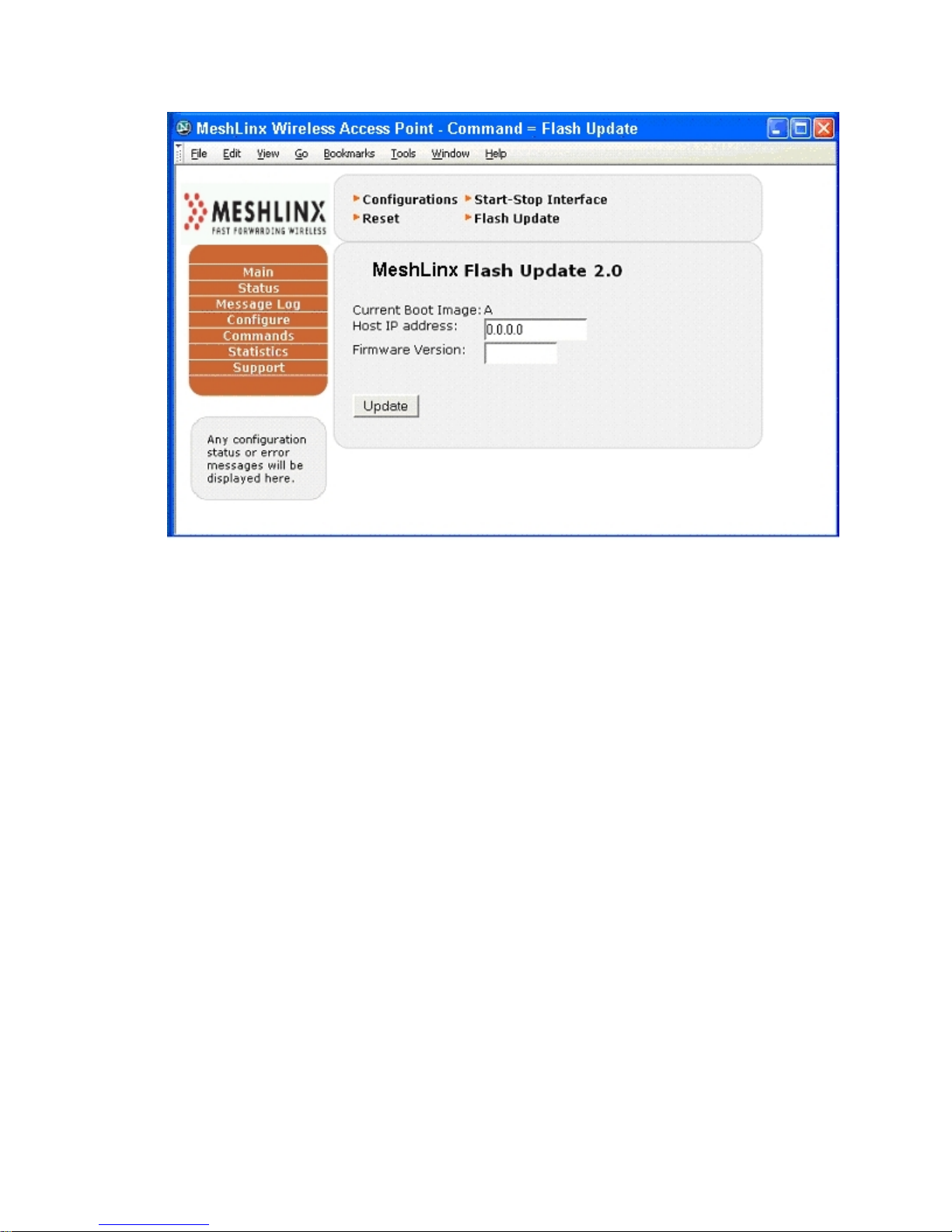
4.2.4.3 Update from the Web Interface
Setup a TFTP server on either a Linux or Windows system and connect it to the
network.
Copy three image files (XXX_ixp425-le-gnu_waps.jffs2, XXX_ixp425-legnu_rootfs.jffs2, and XXX_ixp425-le-gnu_kernel.bin, where XXX is the build
number) to the TFTP server directory (/tftpboot on Linux).
Start the AP and configure its IP address so it can reach the TFTP server.
Launch the web browser
Connect to the AP by typing in the IP address of the AP in the browser
Log into the Ap via web interface when prompted. (NOTE: password is case-
sensitive)
Login: admin
Password: MeshLinx
Navigate and select Commands->Flash Update
Type TFTP server IP address into the Host IP address slot
Type XXX build number into the Firmware Version slot
Click on the Update button
If the update is successful, please power the MWI-5000 System off and then on.
The next boot will use the newly installed image.
MESHLINX CONFIDENTIAL 3
Page 39
MeshLinx MWI-5000 User Guide
4.2.4.4 Update from via RedBoot
If the previous flash image is damaged, it may be necessary to revert to the last
known-good flash image via RedBoot.
Setup a TFTP server on either a Linux or Windows system and connect it to the
network.
Copy three image files (XXX_ixp425-le-gnu_waps.jffs2, XXX_ixp425-legnu_rootfs.jffs2, and XXX_ixp425-le-gnu_kernel.bin, where XXX is the build
number) to the TFTP server directory (/tftpboot on Linux).
Reboot the AP and press Control-C immediately to get in the RedBoot screen
Type flash –l <local IP address> –h <TFTP server IP address>
-t XXX
available on the same subnet with the TFTP server.
Once the firmware update is completed, the AP should automatically reboot itself.
The AP is now operational.
( at the RedBoot> prompt) where local IP address is any static IP address
4.3 Web Interface
The Web interface provides the simplest means for configuring and managing the
MWI-5000 System. You can access it through the wired Ethernet connection or the
MESHLINX CONFIDENTIAL 3
Page 40
MeshLinx MWI-5000 User Guide
wireless interface. The IP address of the client device (Ethernet NIC or wireless
NIC) should be set to an address in the same subnet as the MWI-5000 System,
(e.g., if the MWI-5000 System is set to IP address 192.168.1.1, the NIC should be
set to 192.168.1.x, where x is a number between 2 and 255, so that the full IP
address does not conflict with another device in the subnet).
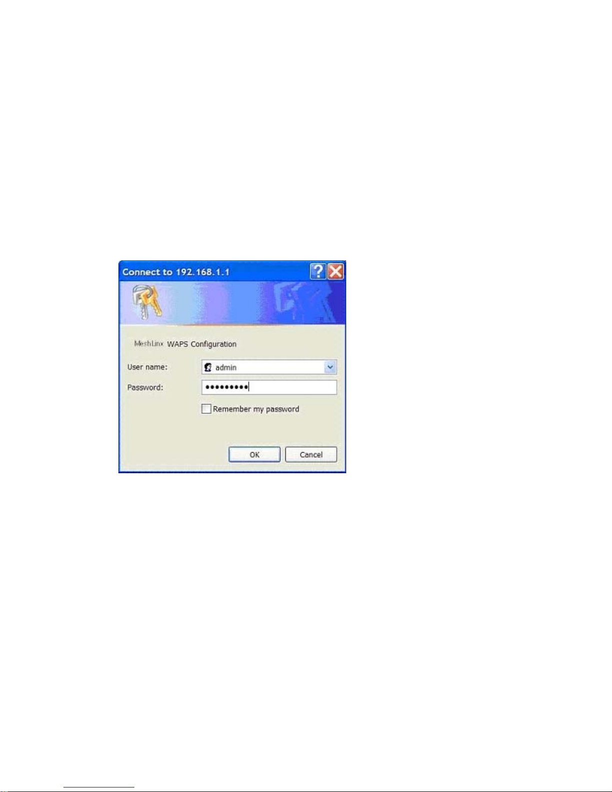
Open a Web browser and enter the address of the MWI-5000 System (e.g.,
http://192.168.1.1). A login and password are required to access the system, as
shown in Figure 4.. The defaults are login: admin and password: m3shl1nx.
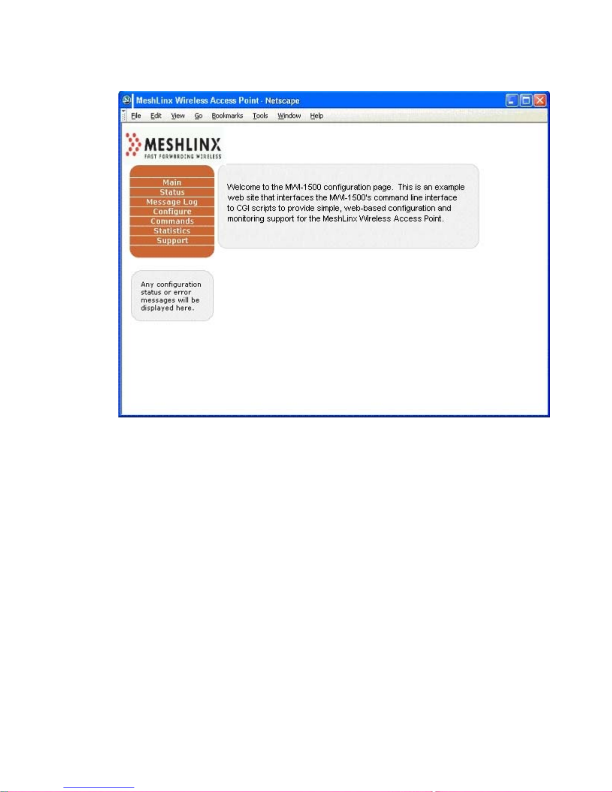
(passwords are case-sensitive) This connects to the MWI-5000 System Web
interface, and the main screen displays, as shown in Figure 4.3
Figure 4.2 Login Window
MESHLINX CONFIDENTIAL 4
Page 41
MeshLinx MWI-5000 User Guide
Figure 4.3 MWI-5000 System Main Window
The box on the left side of the screen is the main menu. The Status window
provides information about the current system version numbers, and about the
associated stations and wif-by-wif throughput information. Access basic system
configuration via Configure. The Commands option allows you to set and change
the configuration files, and contains controls for starting and stopping all system
interfaces as well as a system reset button. While the MWI-5000 System is in
operation, statistics are being captured and can be accessed from the Statistics
window. The Support page provides links to the online Help files and the
MeshLinx Web site, and contains the link for updating system firmware.
The Web interface is designed for easy customization, enabling OEMs to change
the look and feel to match their own equipment interfaces.
4.3.1 The Status Page
The Status page displays the current system status.
MESHLINX CONFIDENTIAL 4
Page 42
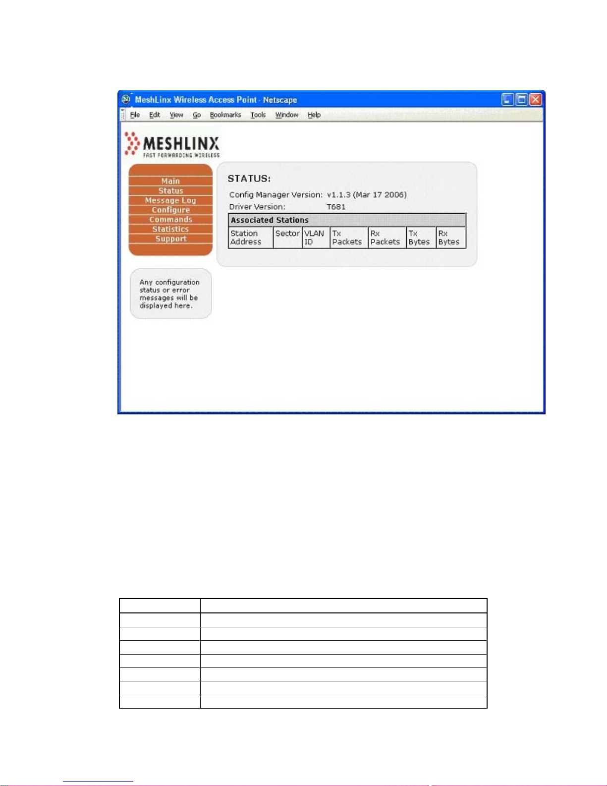
MeshLinx MWI-5000 User Guide
Figure 4.4 Status Page
The Status page displays software and firmware versions, and the
status of the stations associated with the MWI-5000 System.The
Message Log
The message log page displays events that are capt ured during the startup and
operation of the MWI-5000 System. Table 4.1 lists all of the possible messages
with the message category. The time shown in the log represents the time since the
last power-on, in days:hours:minutes:seconds.hundredths. Figure 4.4 shows a
typical message log shortly after system startup.
Table 4.1 Message Log Information
Category Message
information Station "MAC" associated with se ctor "X".
information Station "MAC" disassociated with sector "X" due to: "Y".
information Station "MAC" denied authentication on sector "X" due to: "Z"
information Station "MAC" denied association on se ctor "X" due to: "Z"
information Backhaul link establishe d between "MAC" on channel X
warning Backhaul link disconnected.
information Access point running firmware version "VERSION"
MESHLINX CONFIDENTIAL 4
Page 43

MeshLinx MWI-5000 User Guide
information HTTP server started.
warning HTTP server failed to start.
information SNMP server started.
warning SNMP server failed to start.
information TCP/IP stack started with address "X"
warning Failed to connect with DHCP server.
warning TCP/IP stack failed to start due to IP address conflict.
information DHCP server started.
warning DHCP server failed to start due to: "Y"
warning Sector "X" failed to start due to: "Y".
information RADIUS server started.
warning RADIUS server failed to start due to: "Y"
error Failed to connect to radius server "IP Address"
information Link established on ethernet port at "X speed"
warning Link lost on ethernet port.
information Access point started.
warning Access point failed to start due to: "Y"
information Auto configuration starte d.
information Auto configuration com pleted.
error Auto configuration failed to complete due to "Y"
error "Error X occurred that should never occur."
information Station "MAC" re-associated with sector "X".
information Sector "X" started.
information
information
information
information
warning TKIP MIC error in packet received from station "X"
Sector "X" stopped.
Link established on ethernet port.
Ethernet auto negotiated "X" speed" and "Y" duplex mode.
Ethernet forced to "X" speed and "Y" duplex mode
Figure 4.5 Message Log Display
MESHLINX CONFIDENTIAL 4
Page 44
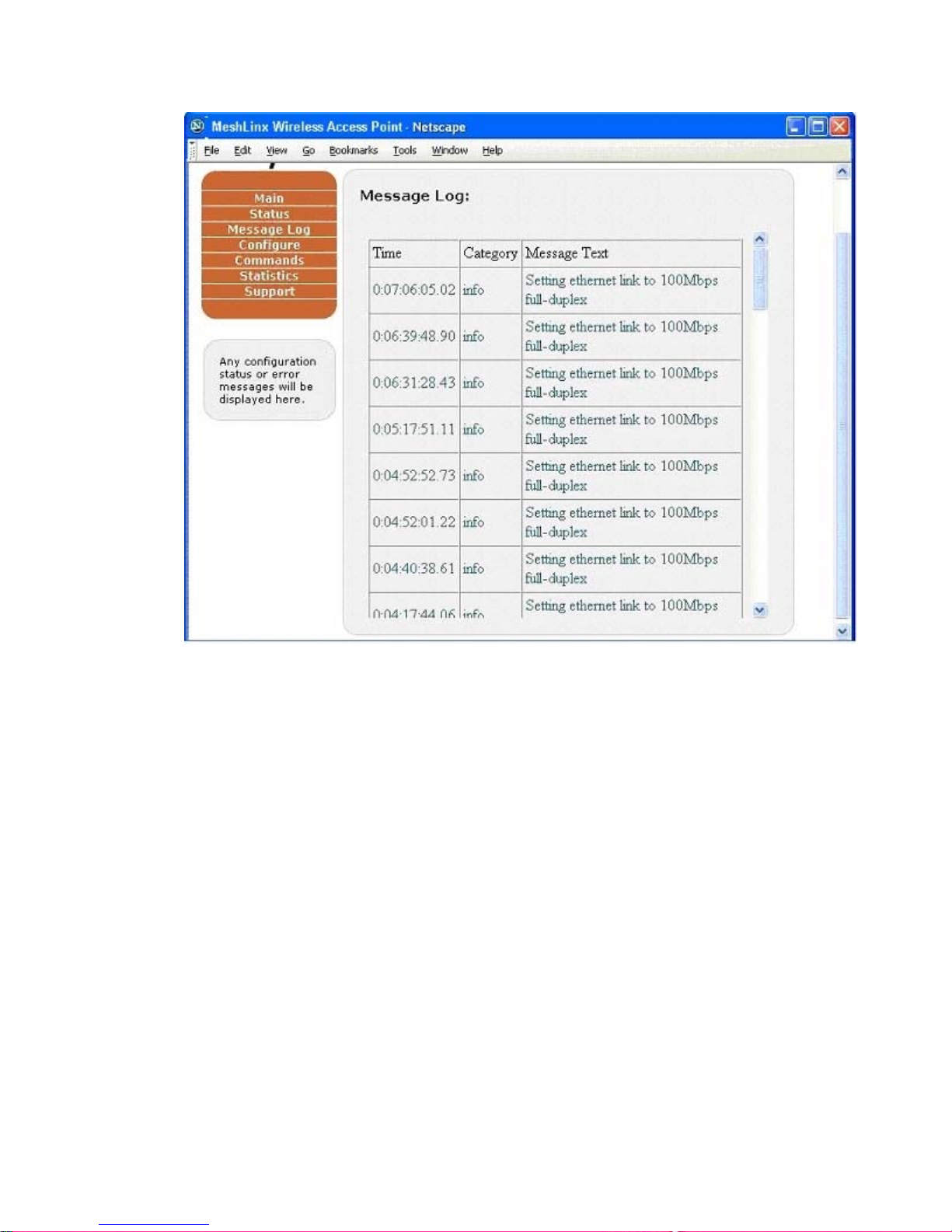
MeshLinx MWI-5000 User Guide
4.3.2 Configure Menu
The Configure menu has fourteen submenus that group system configuration into
logical categories:
• System
• SSID/Security/VLAN
• Filter
• Password
• TCP/IP
• DHCP
• HTTP
• RADIUS
• SNMP
• Ethernet
MESHLINX CONFIDENTIAL 4
Page 45
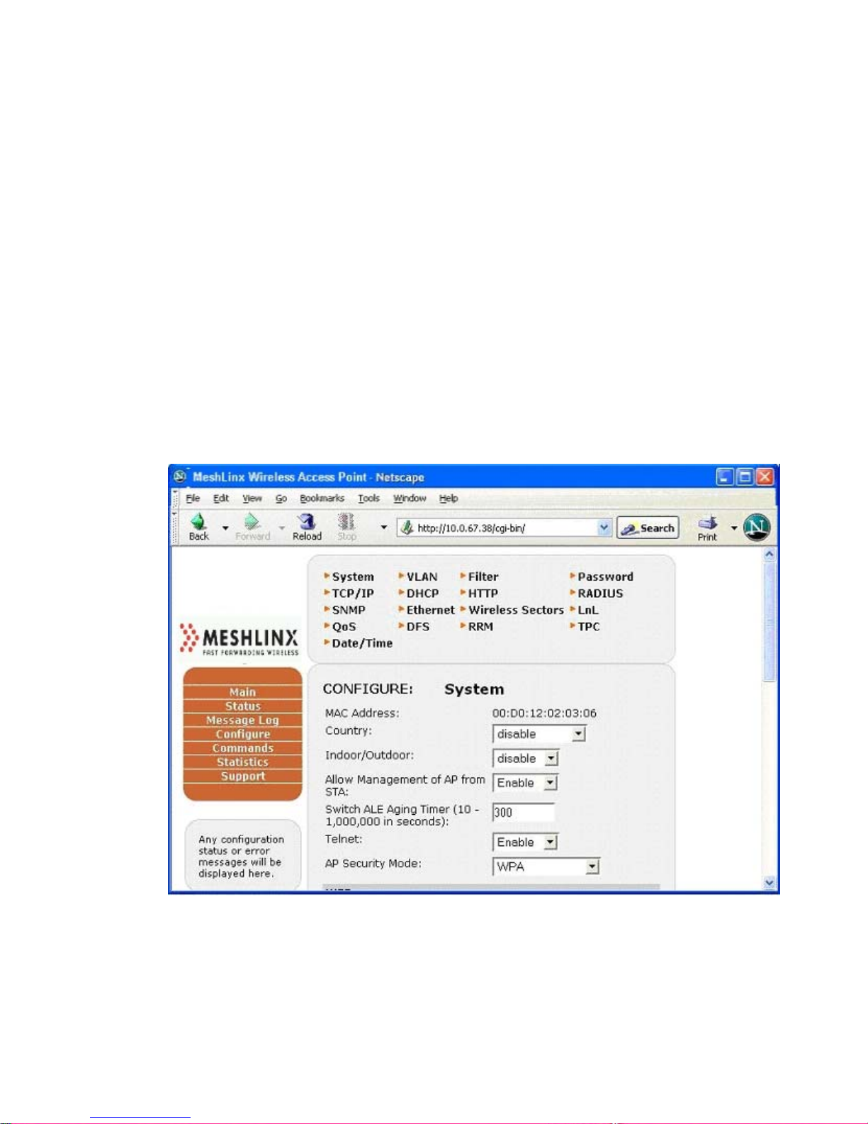
MeshLinx MWI-5000 User Guide
• Wireless Sectors
• Listen and Learn
• QoS
• DFS
• RRM
• TPC
• Date and Time.
4.3.3 Configure - System :
Figure 4.6a Configure System Window (Top Portion)
The Configure>System menu includes the auto-configuration setting, and all of
the authentication and security settings. The Mode menu includes selections for
Range or Capacity. This determines the sector preferences during autoconfiguration, for support for either range mode (3-channel mode) or capacity
mode (6-channel mode).
MESHLINX CONFIDENTIAL 4
Page 46
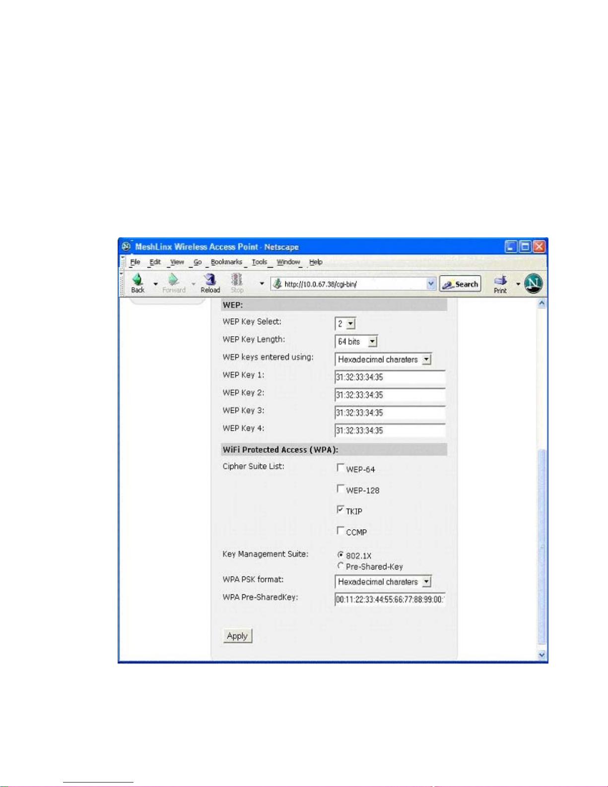
MeshLinx MWI-5000 User Guide
The AP Security Mode drop-down menu includes settings for Open
(authenticate only stations with no security enabled), WEP (authenticate only
stations with WEP enabled), WPA-Only (authenticate only stations with WPA
enabled), WPA2, WPA+WPA2 (authenticate only stations with WPA or WPA2
enabled) or TSN (Transition Security Network – authenticates stations regardless
of security mechanism used).
Figure 4.6b Configure System Window (bottom section)
MESHLINX CONFIDENTIAL 4
Page 47
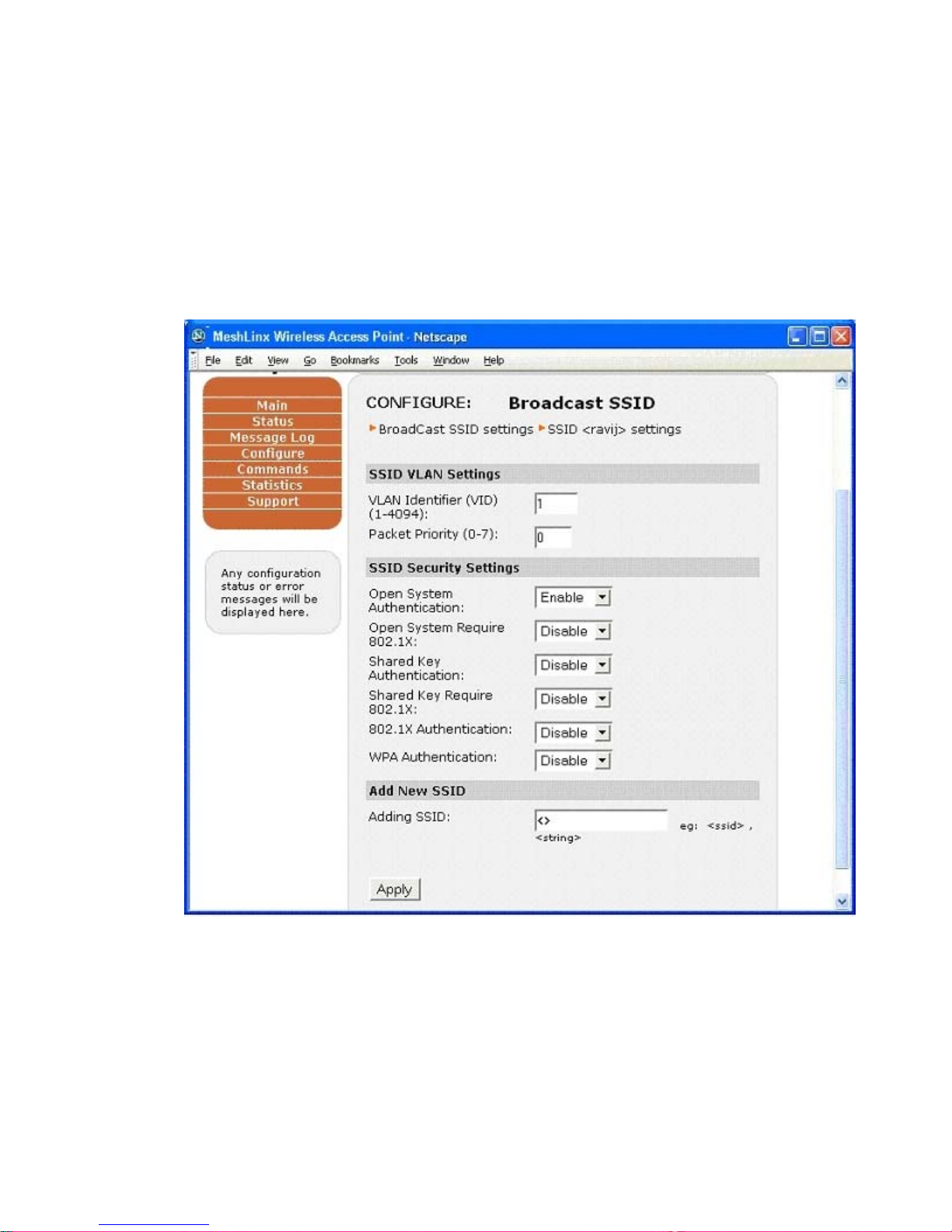
MeshLinx MWI-5000 User Guide
4.3.4 Configure - SSID/Security/VLAN :
Figure 4.7 Configure SSID/Security/VLAN Window
The Configure>SSID/Security/VLAN window includes all of the settings used for
setting VLAN configuration.
MESHLINX CONFIDENTIAL 4
Page 48
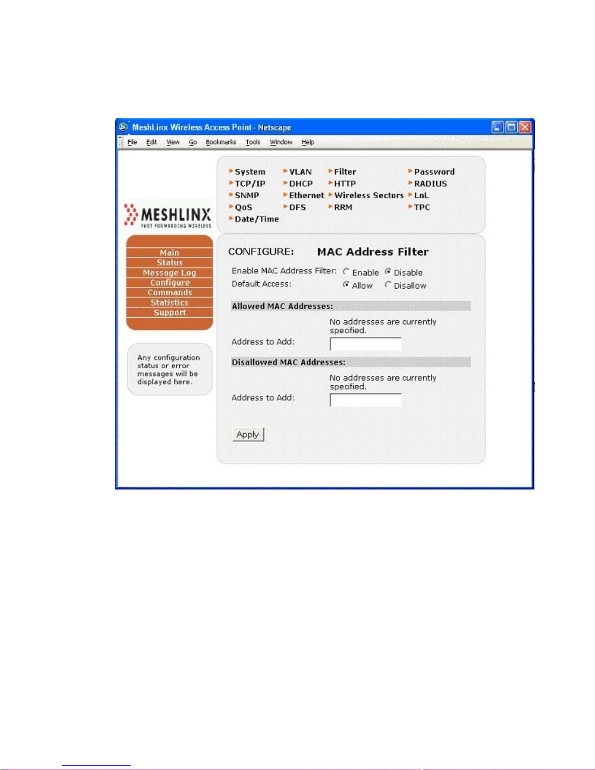
MeshLinx MWI-5000 User Guide
4.3.5 Configure - Filter :
Figure 4.8 Configure Filter Window
MESHLINX CONFIDENTIAL 4
Page 49
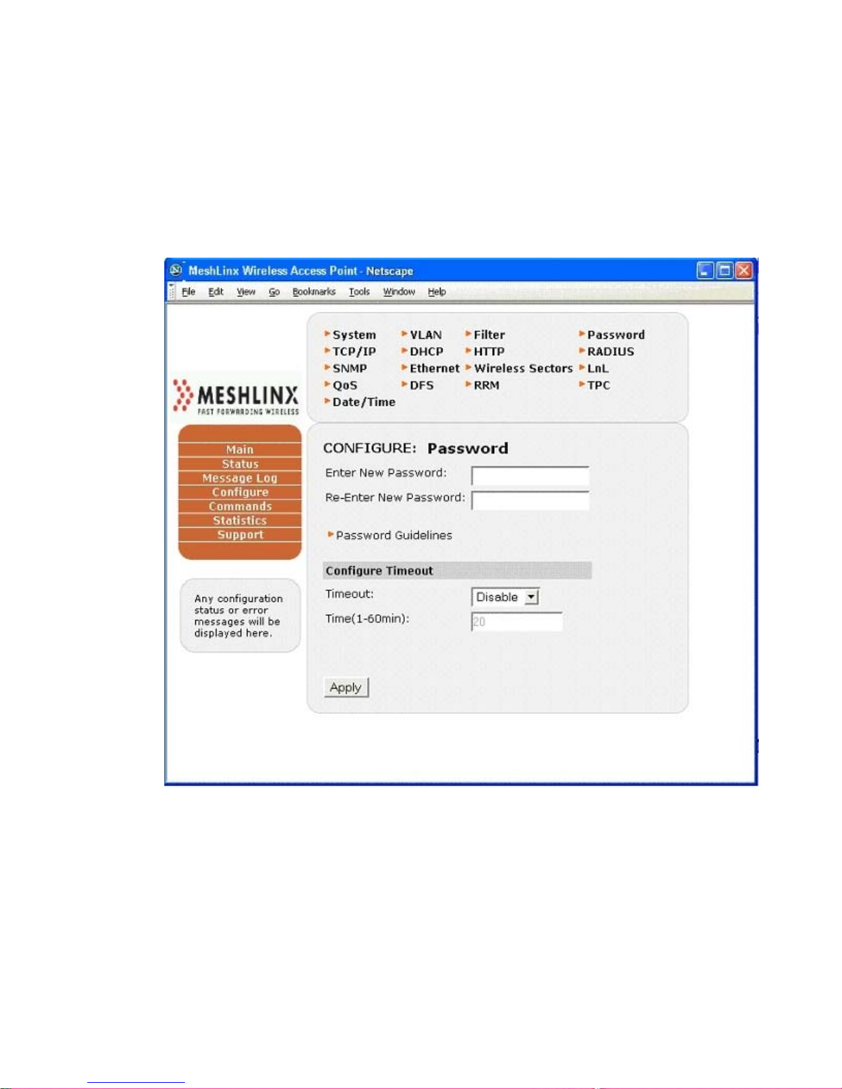
MeshLinx MWI-5000 User Guide
The Configure>Filter window allows you to select MAC
addresses to allow or to disallow.
4.3.6 Configure - Password :
Figure 4.9 Configure Password Window
MESHLINX CONFIDENTIAL 4
Page 50
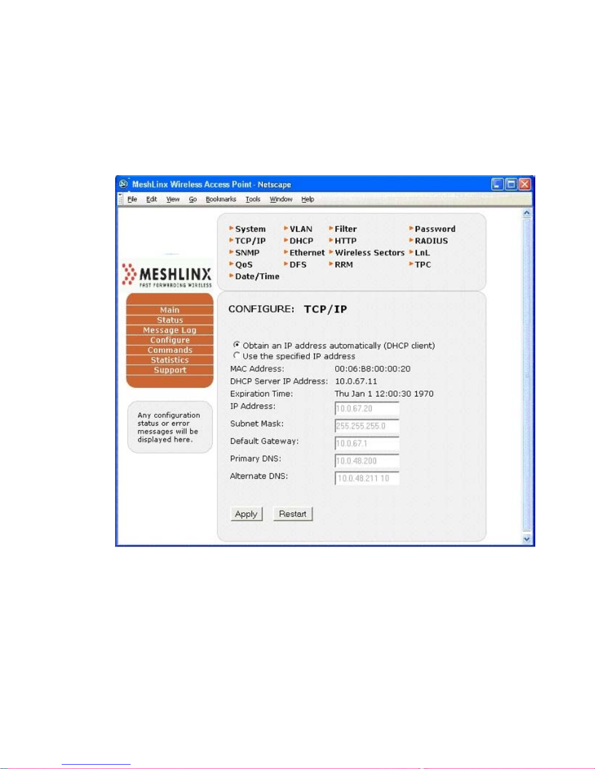
MeshLinx MWI-5000 User Guide
The Configure>Password window allows you to change the default
password.
4.3.7 Configure - TCP/IP :
Figure 4.10 Configure - TCP/IP Window
The Configure>TCP/IP window contains the settings for the system IP addresses,
and the option to have it obtain its IP address automatically (DHCP client).
MESHLINX CONFIDENTIAL 5
Page 51
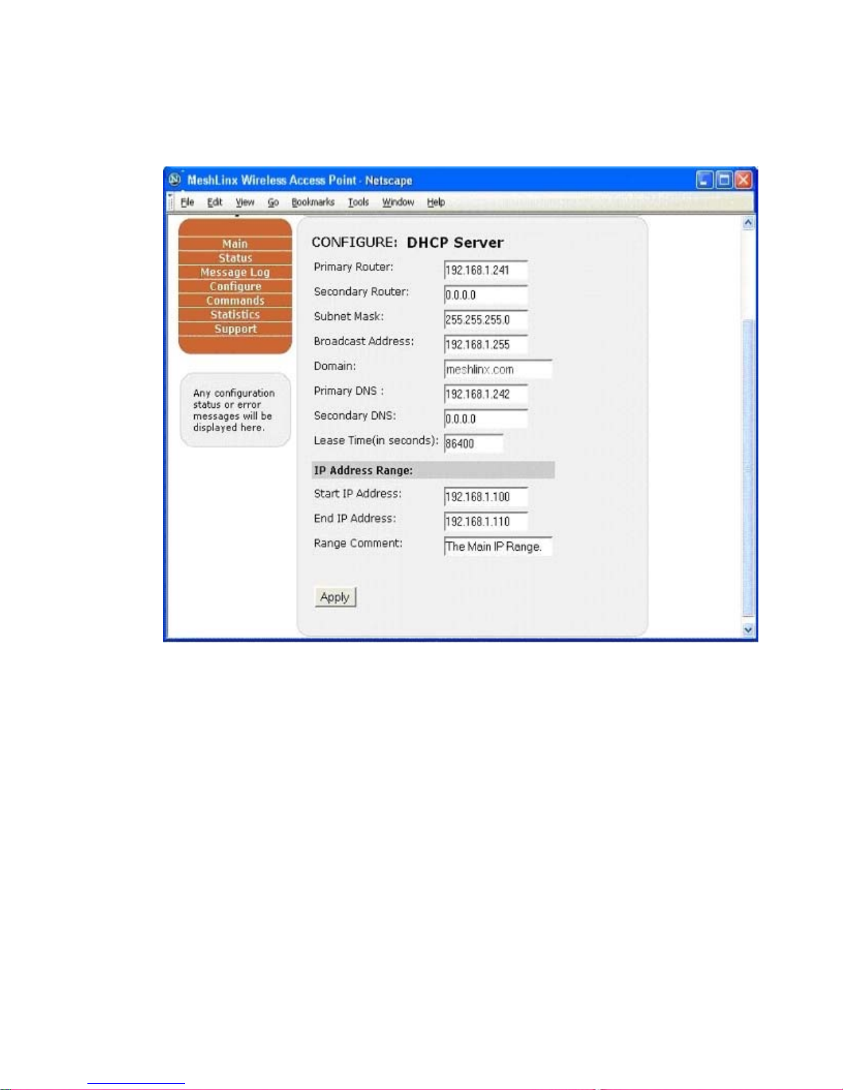
4.3.8 Configure – DHCP :
Figure 4.11 Configure – DHCP Window
MeshLinx MWI-5000 User Guide
MESHLINX CONFIDENTIAL 5
Page 52
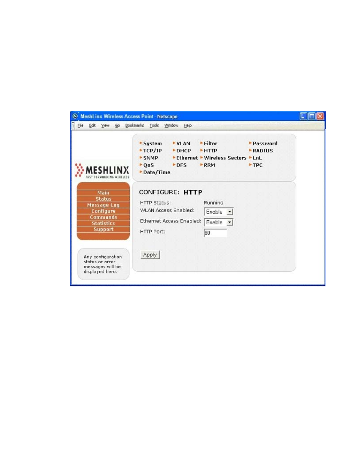
MeshLinx MWI-5000 User Guide
The Configure>DHCP window includes all of the settings for
DHCP hosting.
4.3.9 Configure – HTTP :
Figure 4.12 Configure HTTP Window
MESHLINX CONFIDENTIAL 5
Page 53
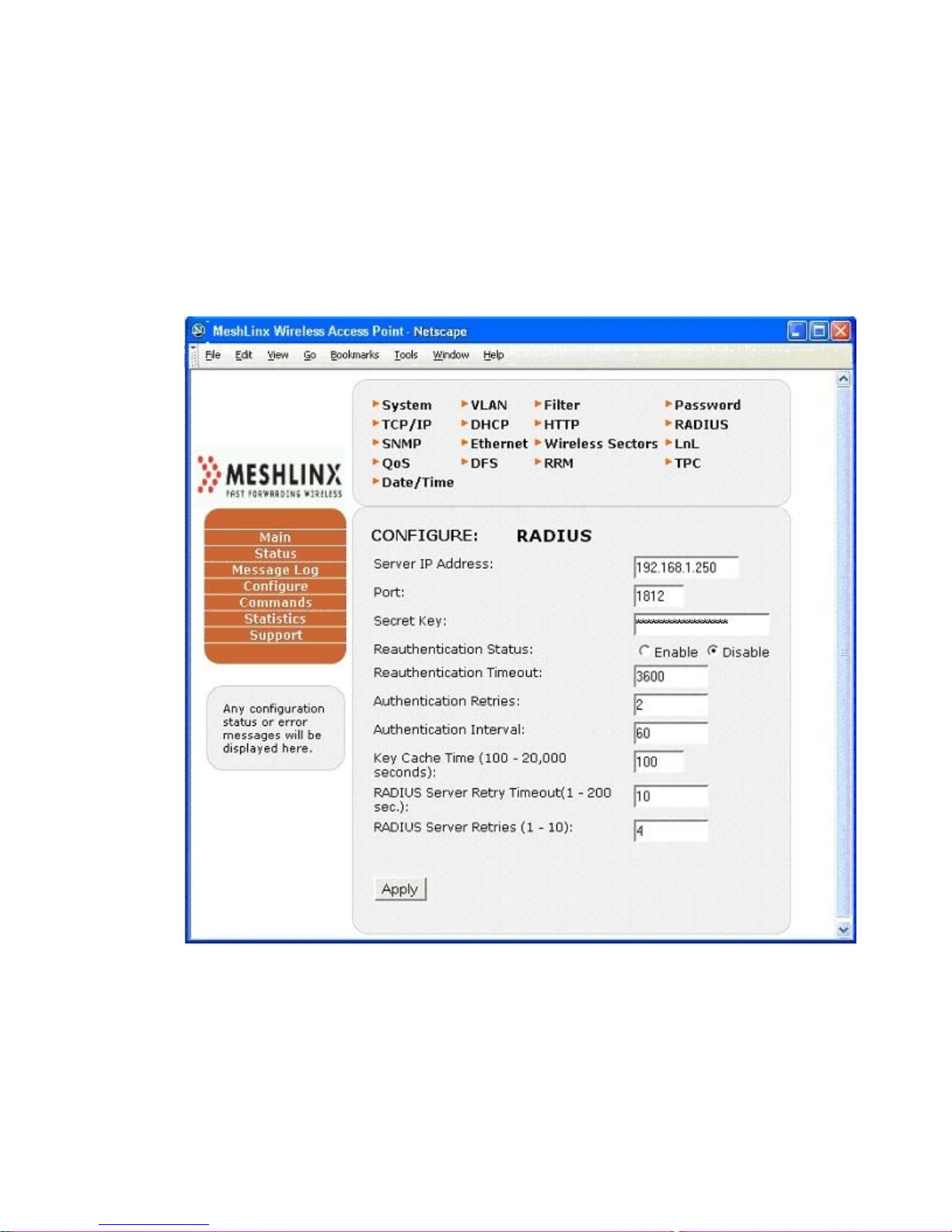
MeshLinx MWI-5000 User Guide
The Configure>HTTP window displays the status of HTTP
Interface, allows you to configure WLAN Access Enable,
Ethernet Access Enable, and also to change the HTTP port.
4.3.10 Configure – RADIUS :
Figure 4.13 Configure RADIUS Window
The Configure>RADIUS window includes all of the settings used for the
RADIUS server, and sets the re-authentication parameters.
MESHLINX CONFIDENTIAL 5
Page 54
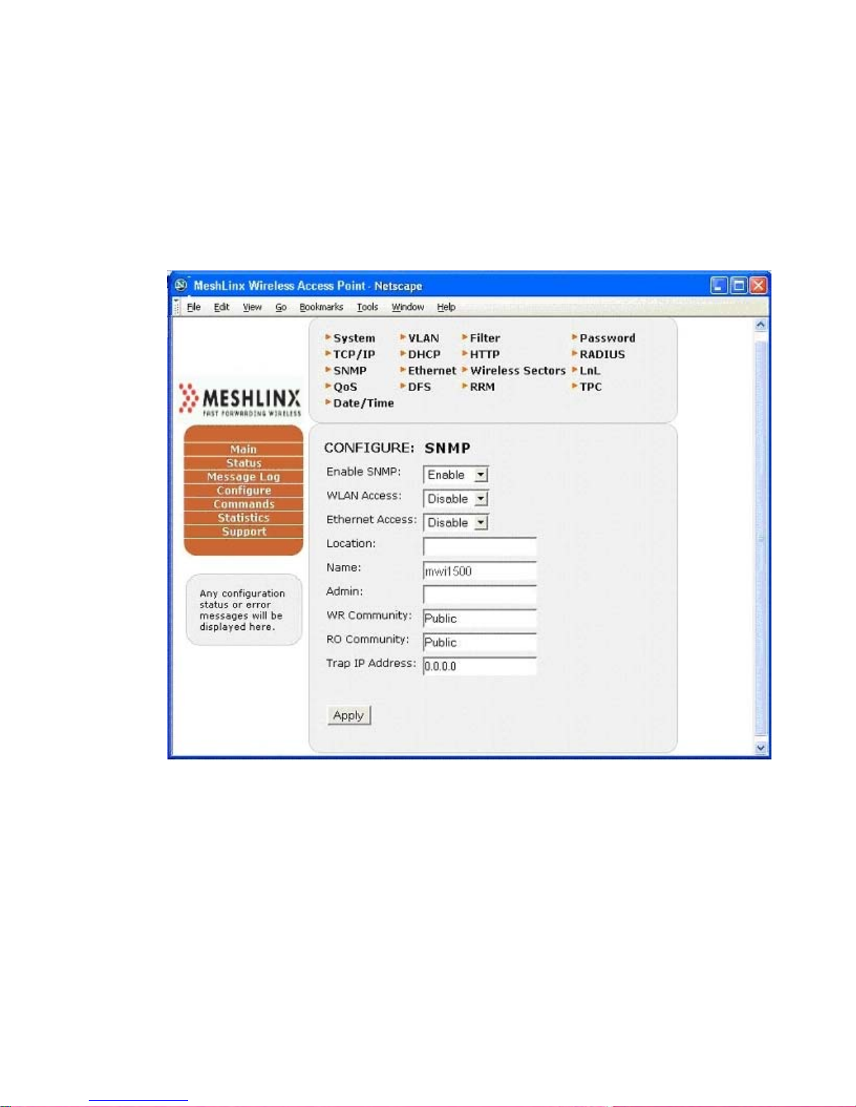
MeshLinx MWI-5000 User Guide
4.3.11 Configure - SNMP
Figure 4.14 Configure SNMP Parameters.
MESHLINX CONFIDENTIAL 5
Page 55

MeshLinx MWI-5000 User Guide
The Configure > SNMP Interface contains the Access Points` SNMP
Server Parameters.
4.3.12 Configure – Ethernet :
Figure 4.15 Configure Ethernet Window
The Configure>Ethernet menu includes the link speed with duplex and flow
control settings, and displays the current Ethernet port status.
MESHLINX CONFIDENTIAL 5
Page 56
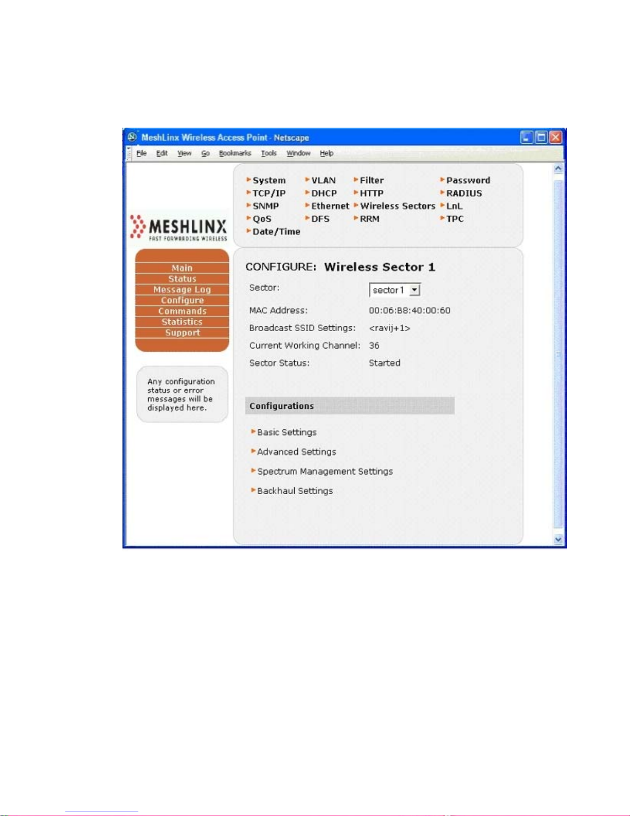
MeshLinx MWI-5000 User Guide
4.3.13 Configure - Wireless Interfaces :
Figure 4.16 Configure Wireless Interfaces Window .
The Configure>Wireless Interface menu has submenus for the
individual WIFs. These menus contain all of the AP settings for the
selected WIF.
4.3.14 Configure – Basic Settings:
Figure 4.17 Configure Wireless Interfaces – Basic Settings.
MESHLINX CONFIDENTIAL 5
Page 57
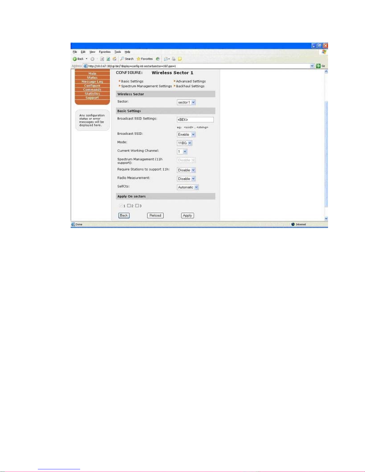
MeshLinx MWI-5000 User Guide
The Configure>Basic Settings includes the basic parameters such as Broadcast
SSID and Enabling or Disabling Spectrum Management and Radio
Measurement and the working Channel of each wif.
4.3.15 Configure – Advance Settings :
Figure 4.18 Configure Wireless WIFs – Advance Settings
MESHLINX CONFIDENTIAL 5
Page 58
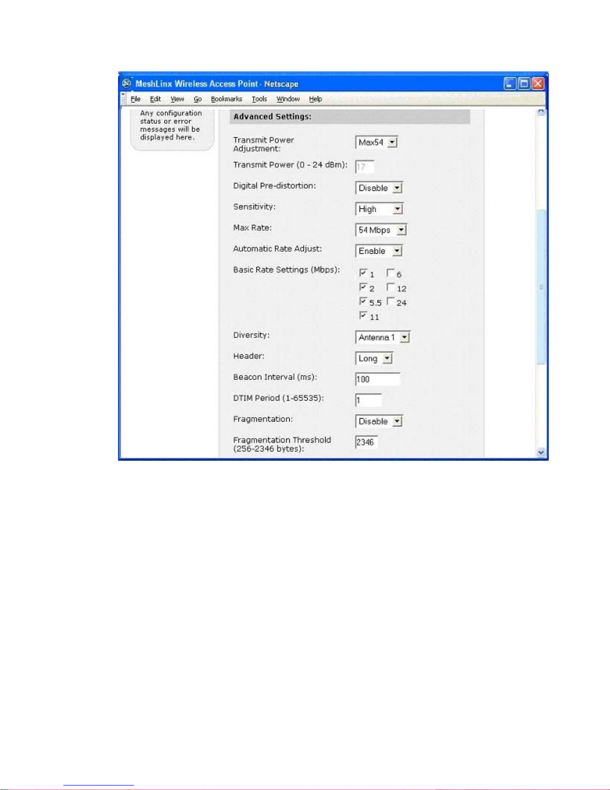
MeshLinx MWI-5000 User Guide
The Configure>Advanced Settings include all the advanced parameters that can
be configured for each WIF.
4.3.16 Configure- Spectrum Management:
Figure 4.19 Configure WIFs – Spectrum Management Settings.
MESHLINX CONFIDENTIAL 5
Page 59
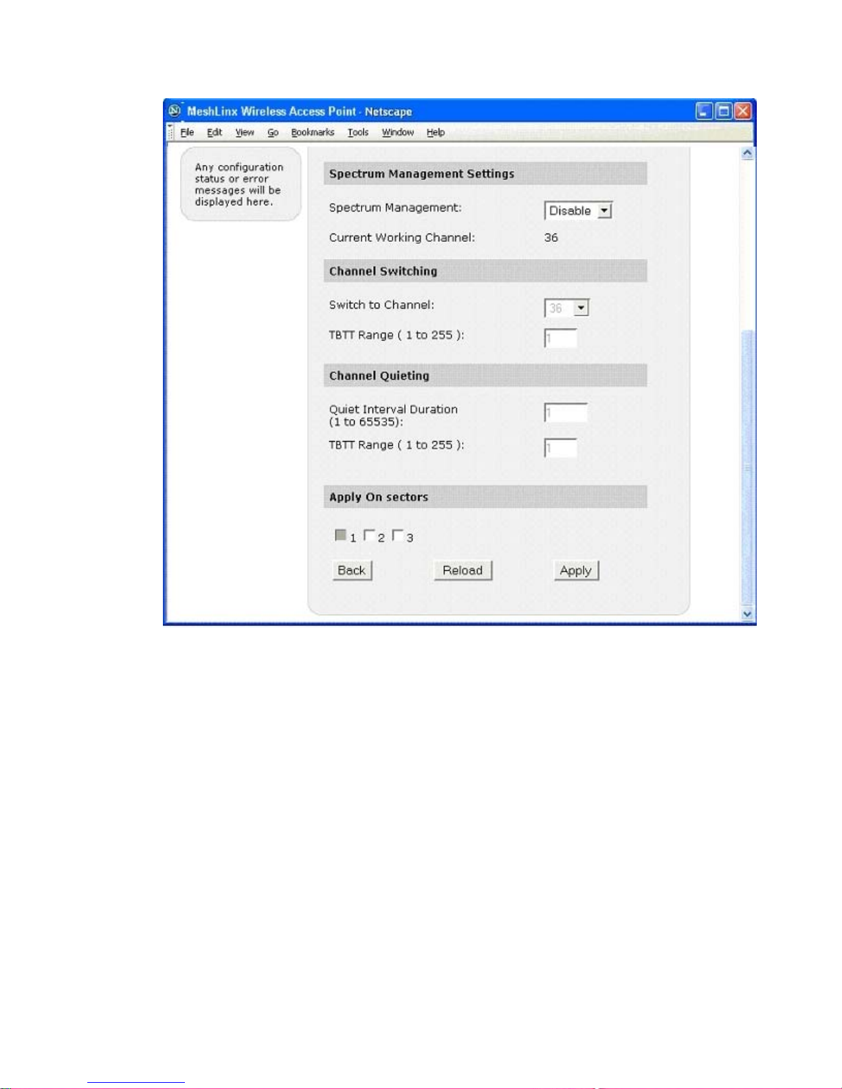
MeshLinx MWI-5000 User Guide
The Configure >Spectrum Management contains the parameters to be set for
Spectrum Management.
MESHLINX CONFIDENTIAL 5
Page 60
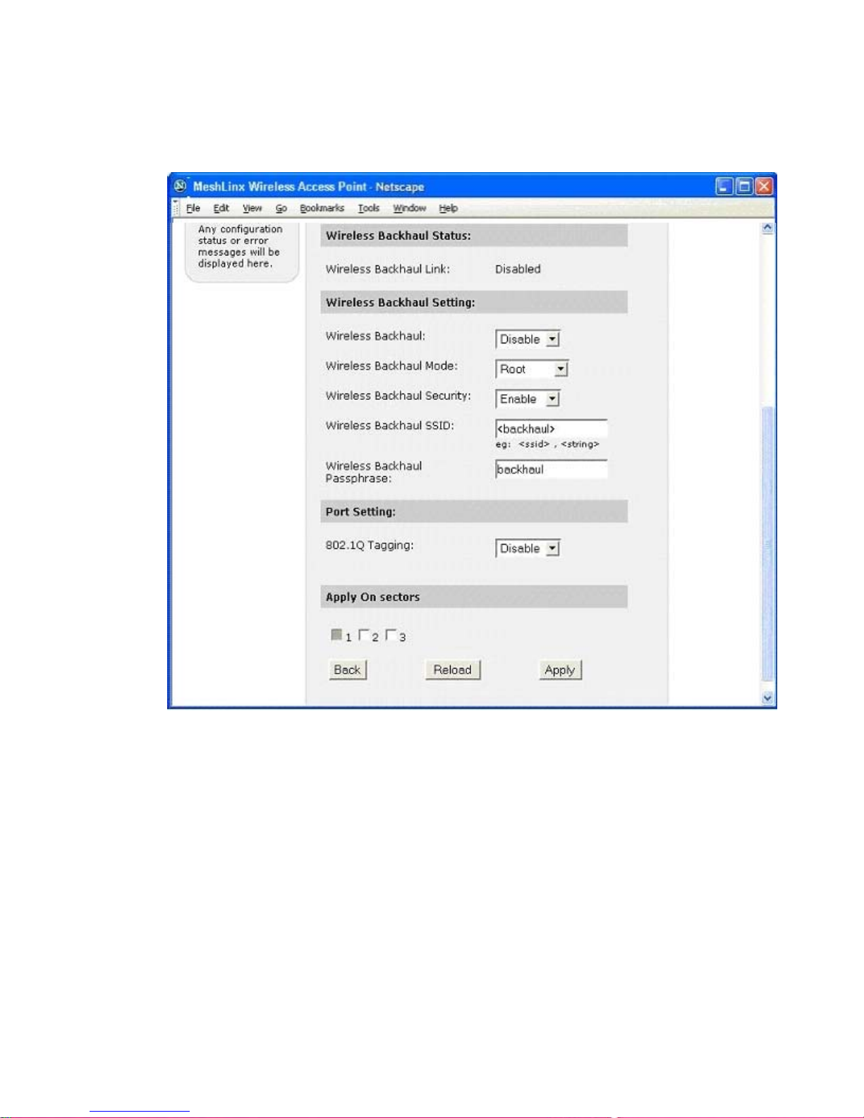
MeshLinx MWI-5000 User Guide
4.3.17 Configure – Backhaul Settings :
Figure 4.20 Configure WIFs – Backhaul Settings.
The Configure > Backhaul Sett ings is used to configure the Backhaul settings on
a particular WIF.
MESHLINX CONFIDENTIAL 6
Page 61
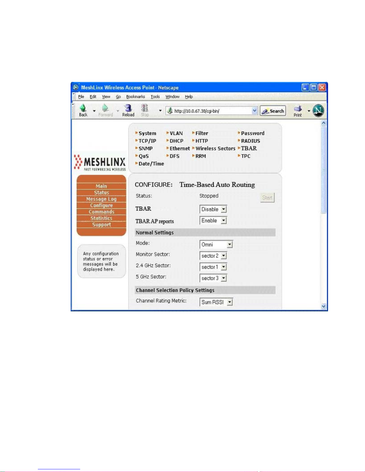
MeshLinx MWI-5000 User Guide
4.3.18 Configure Listen and Learn :
Figure 4.21a Configure Listen and Learn Features (Top
Portion)
Figure 4.21b Configure Listen and Learn Features (Bottom Portion)
MESHLINX CONFIDENTIAL 6
Page 62
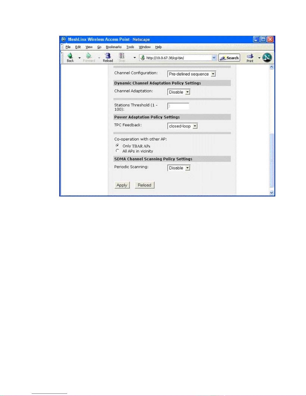
MeshLinx MWI-5000 User Guide
The Configure>Listen and Learn menu provides a convenient interface to all Listen
and Learn features. These features apply to the AP as a whole and allow automatic
configuration and adaptation to the wireless environment.
4.3.19 Configure – QoS :
Figure 4.22a Configure QoS Parameters (Top Portion)
MESHLINX CONFIDENTIAL 6
Page 63
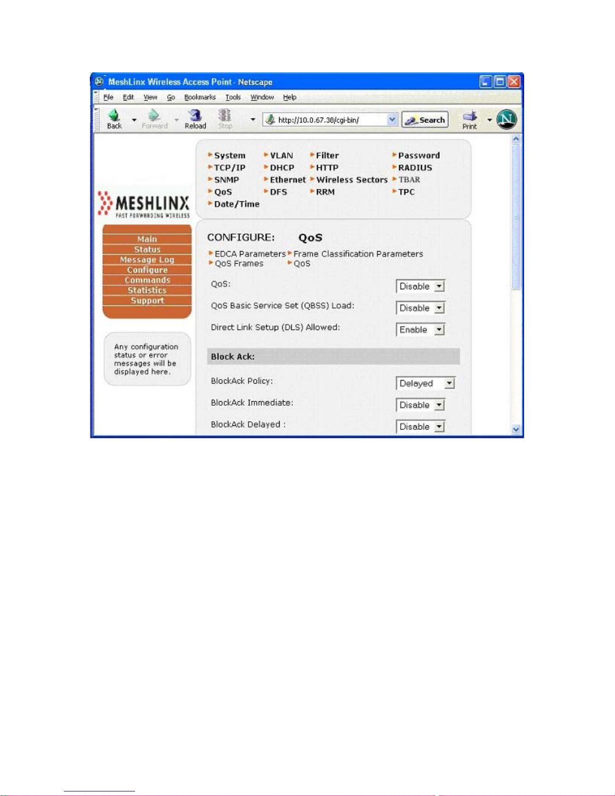
MeshLinx MWI-5000 User Guide
Figure 4.22b Configure QoS Parameters (Bottom Portion)
MESHLINX CONFIDENTIAL 6
Page 64
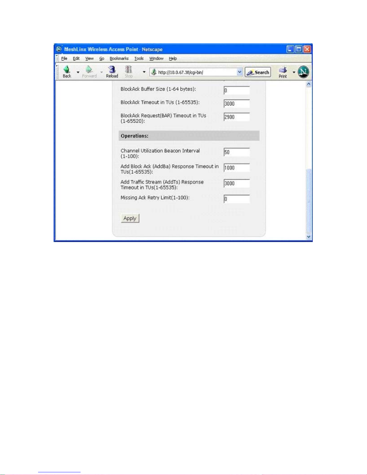
MeshLinx MWI-5000 User Guide
The Configure > QoS contains the standard QoS configurations.
4.3.19.1 Configure QoS – EDCA Parameters :
Figure 4.23a Configure QoS – EDCA Parameters (Top Portion)
MESHLINX CONFIDENTIAL 6
Page 65
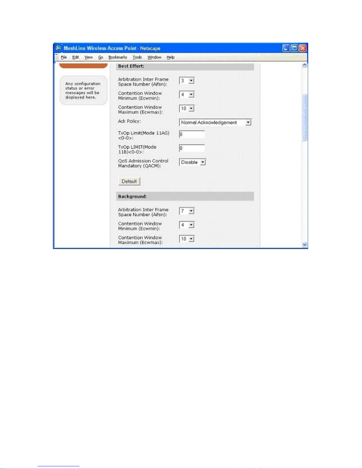
MeshLinx MWI-5000 User Guide
Figure 4.23b Configure QoS – EDCA Parameters (Bottom Portion)
MESHLINX CONFIDENTIAL 6
Page 66
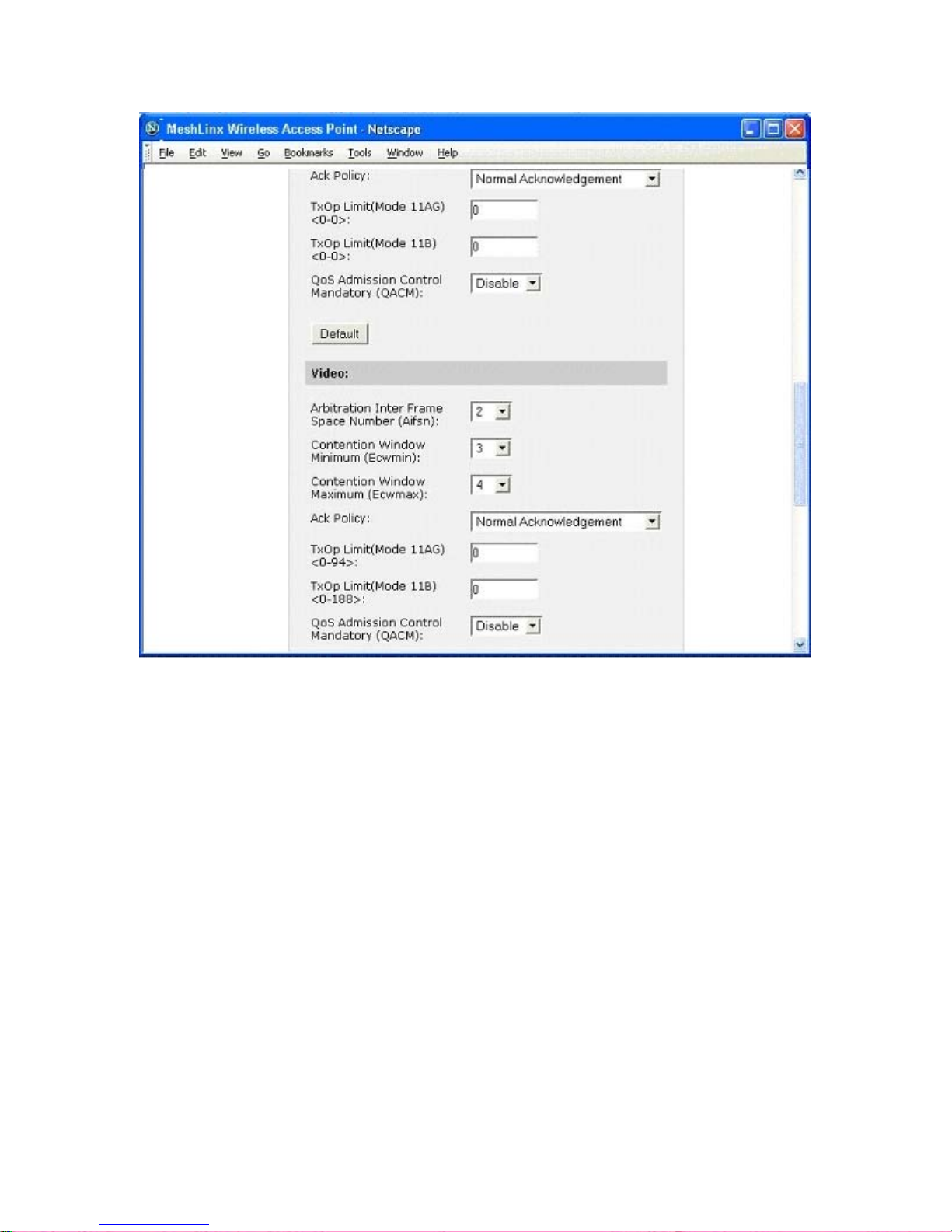
MeshLinx MWI-5000 User Guide
The Config > EDCA Parameters configures the QoS parameters for different types of
Data streams.
4.3.19.2 Configure QoS – Frame Classification Parameters :
Figure 4.24 Configure QoS – Frame Classification Parameters
MESHLINX CONFIDENTIAL 6
Page 67
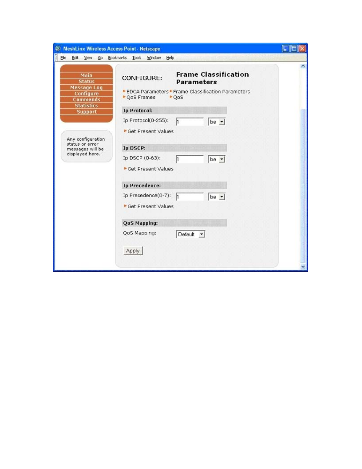
MeshLinx MWI-5000 User Guide
The configure > Frame classification parameters configures the IP protocol attributes
for different types of data streams.
4.3.19.3 Configure QoS – QoS Frames :
Figure 4.25 Configure QoS – QoS Frames
MESHLINX CONFIDENTIAL 6
Page 68
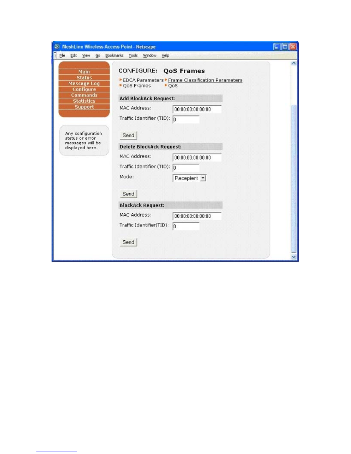
MeshLinx MWI-5000 User Guide
The configure > QoS Frames configures the BlockAck configurations for a MAC
Address.
4.3.20 Configure DFS :
Figure 4.26 Configure DFS Control Parameters
MESHLINX CONFIDENTIAL 6
Page 69
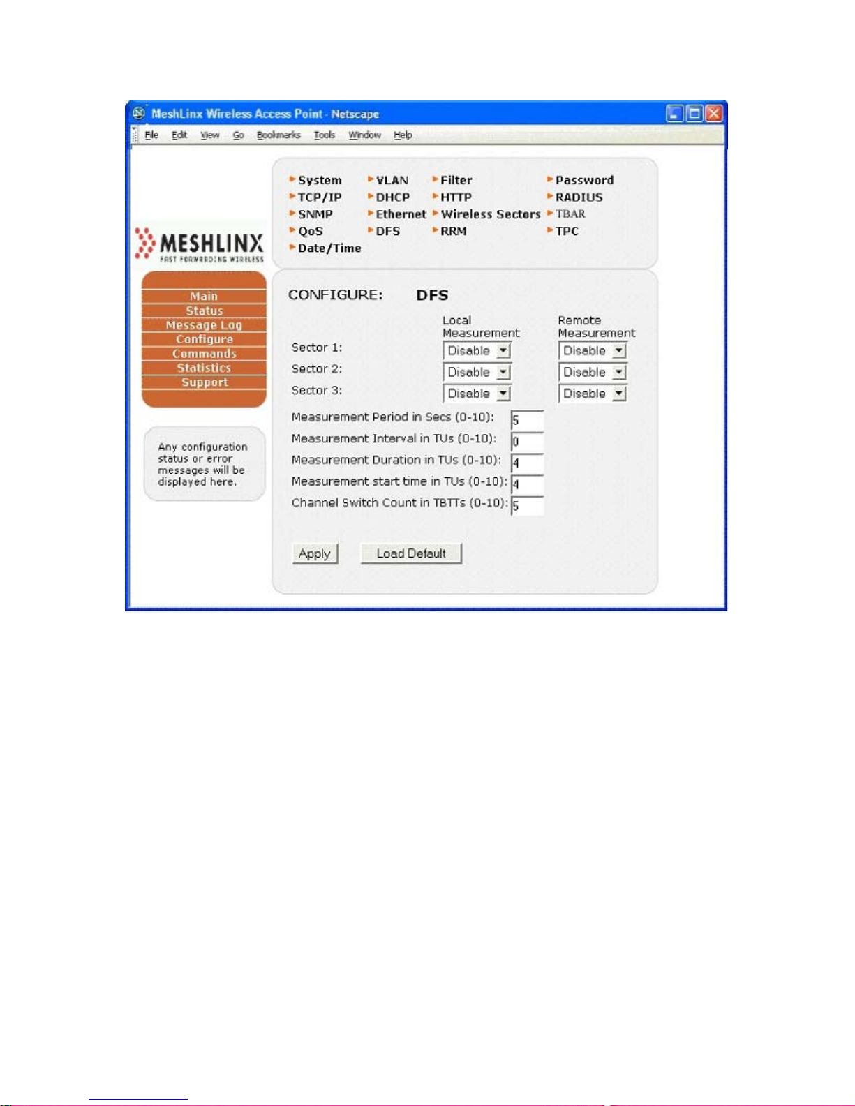
MeshLinx MWI-5000 User Guide
The Configure>DFS menu provides a convenient interface to all 802.11h DFS process
control parameters. These features apply to each WIF.
4.3.21 Configure RRM :
Figure 4.26 Configure RRM Measurement Requests
MESHLINX CONFIDENTIAL 6
Page 70
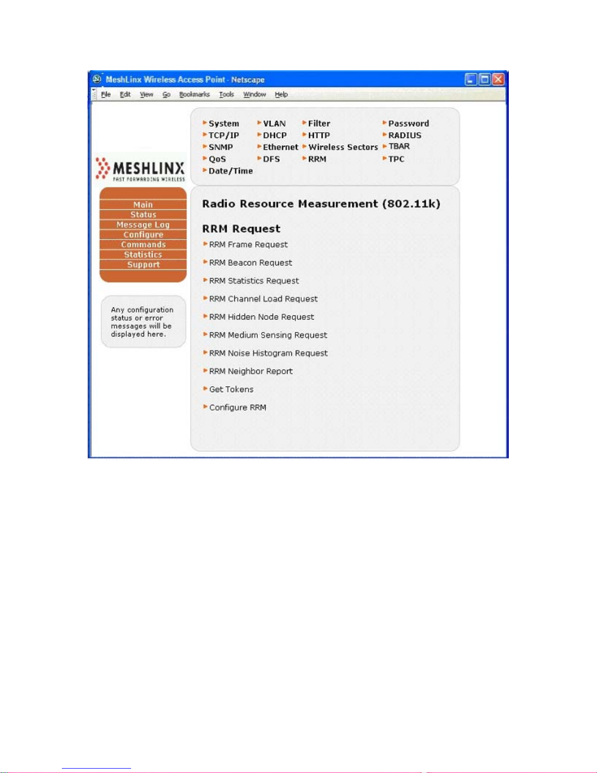
MeshLinx MWI-5000 User Guide
The Configure>RRM menu provides a convenient interface to all 802.11k Remote
Radio Measurement requests. Measurement requests may be issued on any WIF.
4.3.22 Configure TPC :
Figure 4.27 Configure TPC Process Parameters
MESHLINX CONFIDENTIAL 7
Page 71
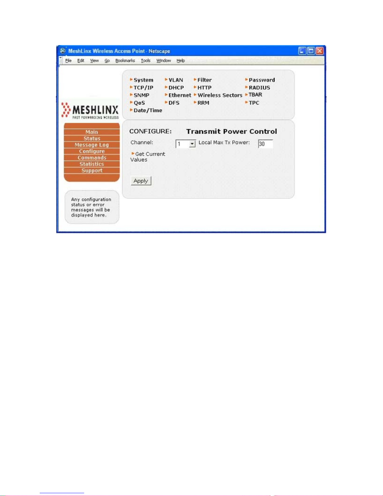
MeshLinx MWI-5000 User Guide
The Configure>TPC menu provides an interface to Transmit Power Capabilities. These
capabilities apply to the AP as a whole, on a per-cha nnel basis.
MESHLINX CONFIDENTIAL 7
Page 72
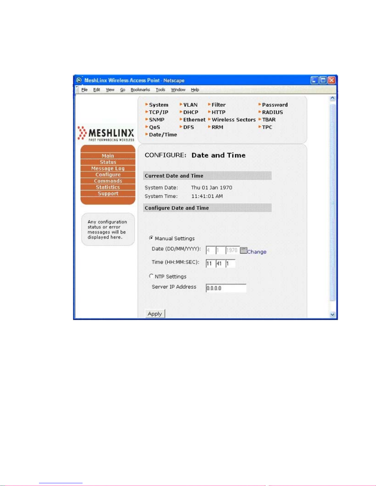
MeshLinx MWI-5000 User Guide
4.3.23 Configure Date and Time :
Figure 4.28 Configure Date and Time
The Configure>Date and Time can be used to configure the system Date and
Time Commands Menu
The Commands menu includes three submenus:
• Configurations
• Start/Stop Interface
• Reset
• Flash Update
MESHLINX CONFIDENTIAL 7
Page 73
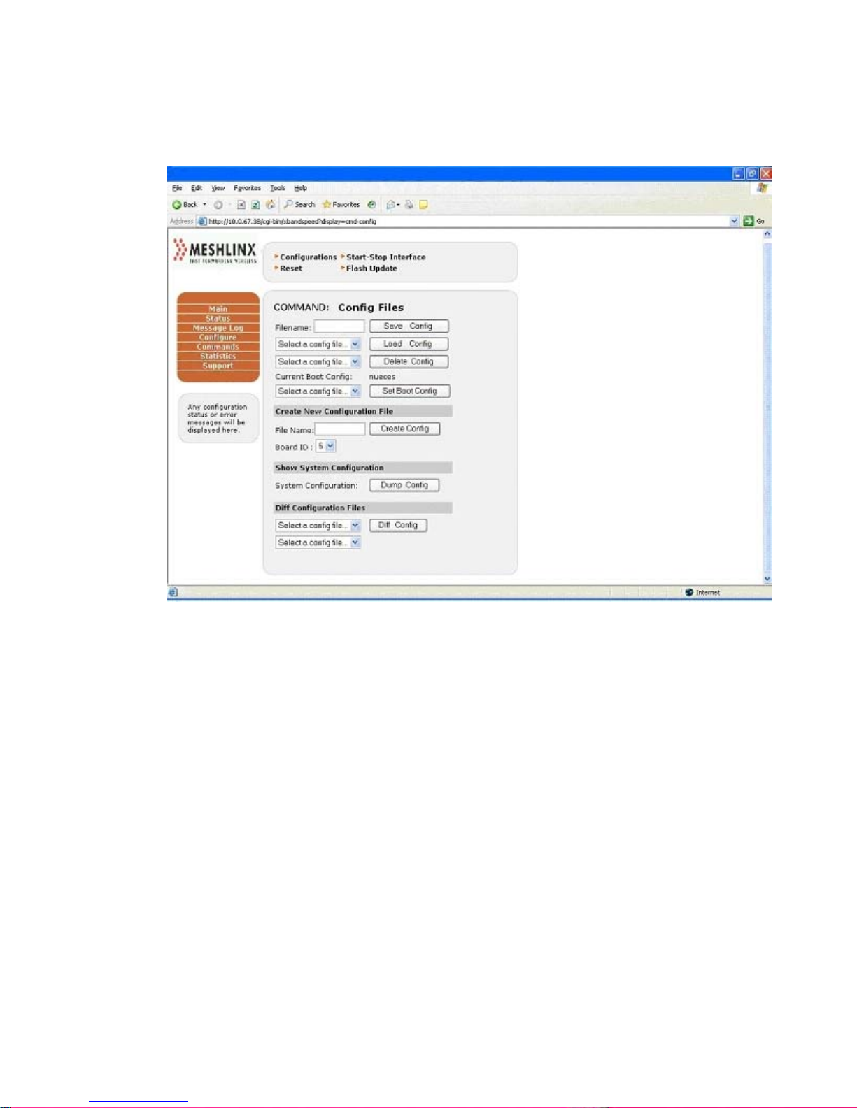
MeshLinx MWI-5000 User Guide
4.3.24 Commands - Configurations :
Figure 4.29 Command Configuration Window
Use the Commands>Configurations menu to manage the configuration files.
Management includes creating a new configuration file, displaying the contents of
current configuration file and displaying the differences of two configuration files.
MESHLINX CONFIDENTIAL 7
Page 74
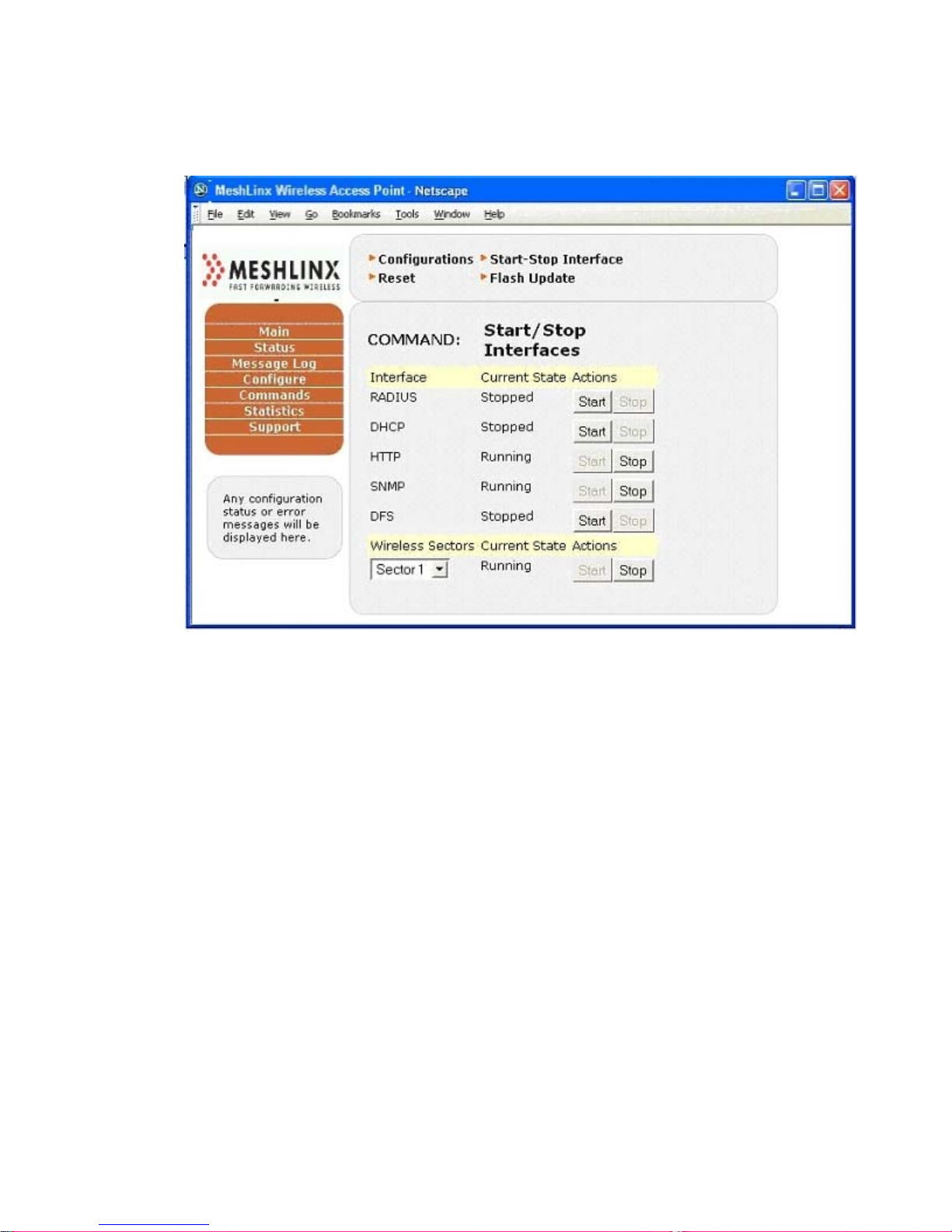
MeshLinx MWI-5000 User Guide
4.3.24.1 Commands - Start/Stop Interface :
Figure 4.30 Command Start/Stop Interface Window
The Commands>Start/Stop Interface window allows you to directly start and
stop all of the system interfaces and shows the current status for each.
MESHLINX CONFIDENTIAL 7
Page 75
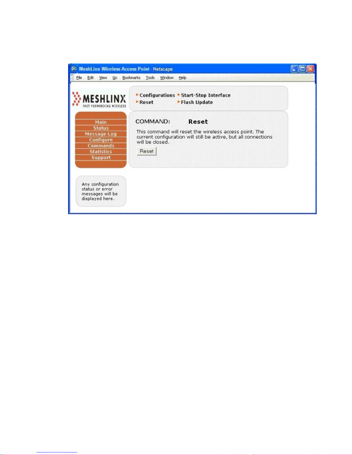
4.3.24.2 Commands – Reset :
Figure 4. 31 Command Reset Window
MeshLinx MWI-5000 User Guide
The Commands>Reset window allows you to perform a system reset. It does not
change the configuration but does close all of the connections.
MESHLINX CONFIDENTIAL 7
Page 76
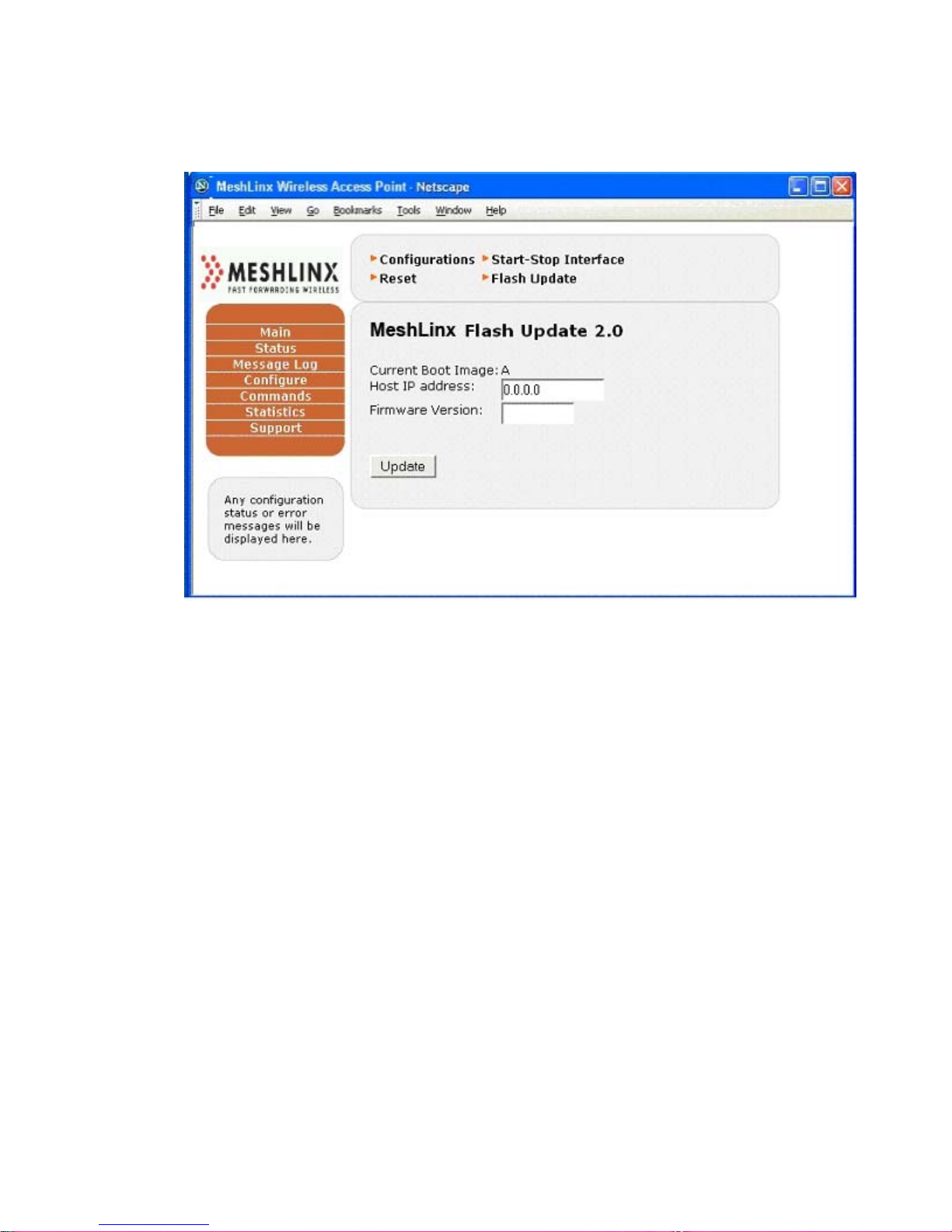
MeshLinx MWI-5000 User Guide
4.3.24.3 Commands – FlashUpdate :
Figure 4. 32 MeshLinx Flash Update.
The Command > Flash Update is used to update the Firmware Image
on the Access Point.
4.3.25 Statistics Window
The Statistics window includes five submenus:
• Ethernet
• WLAN Interfaces
• System
Each of the windows displays the statistics compiled since the last Reset, off-on
power cycle, or Stop/Start cycle of individual interfaces.
MESHLINX CONFIDENTIAL 7
Page 77
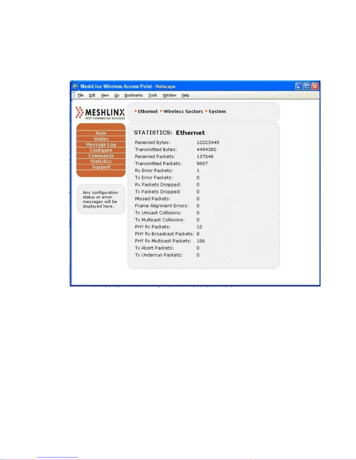
4.3.25.1 Statistics – Ethernet :
Figure 4. 33 Ethernet Statistics Window
MeshLinx MWI-5000 User Guide
MESHLINX CONFIDENTIAL 7
Page 78
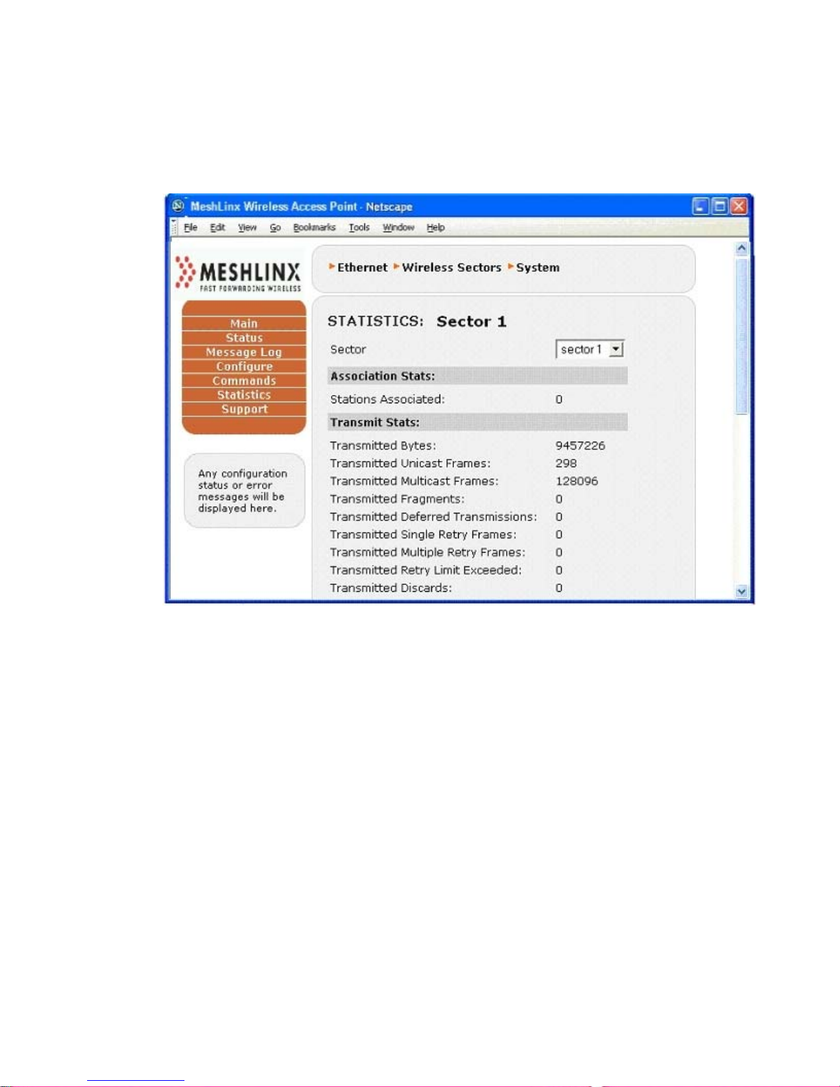
MeshLinx MWI-5000 User Guide
4.3.25.2 Statistics – Wireless Interfaces :
Figure 4.34a Sector 1 (of 3) Statistics Window (Top Portion)
Figure 4.35b Sector 1 (of 3) Statistics Window (Bottom Portion)
MESHLINX CONFIDENTIAL 7
Page 79
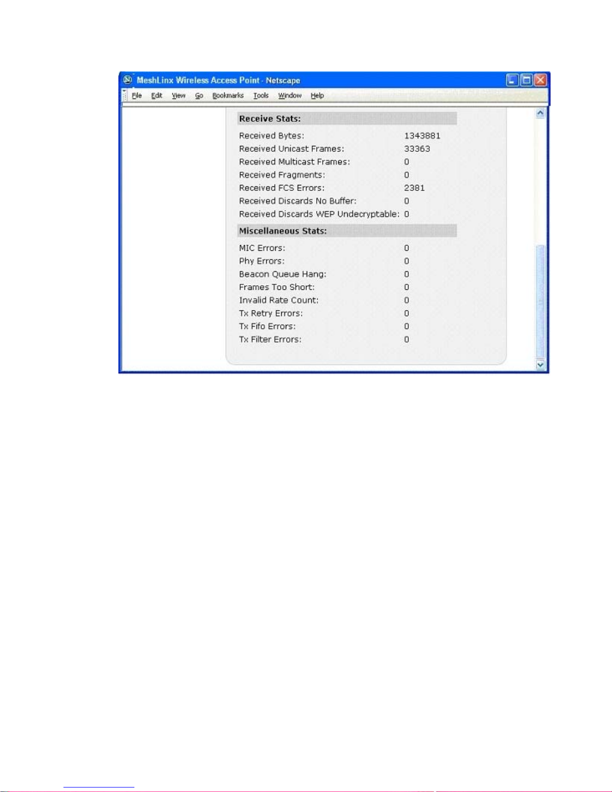
MeshLinx MWI-5000 User Guide
MESHLINX CONFIDENTIAL 7
Page 80
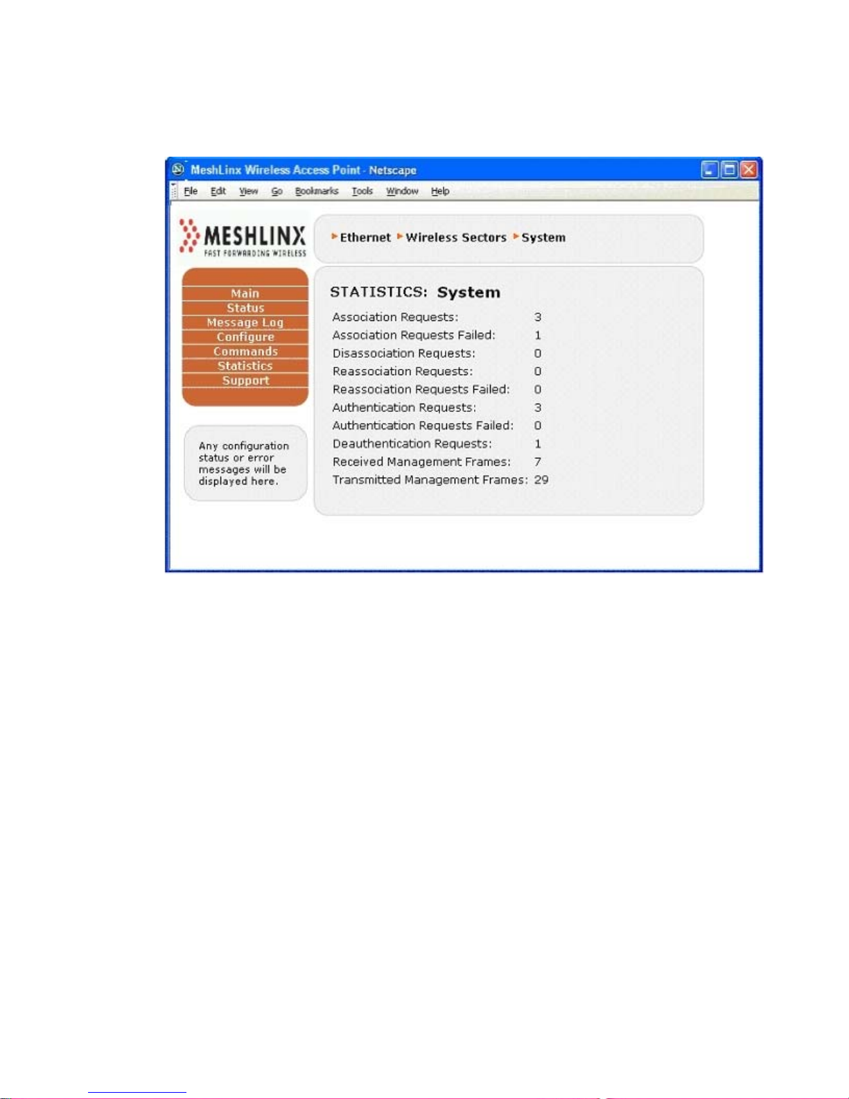
MeshLinx MWI-5000 User Guide
4.3.25.3 Statistics – System :
Figure 4.36 System Statistics Window
4.3.26 The Support Page
The support page provides important links to the MeshLinx Web site, online Help
files, and to the firmware update site to get the latest firmware for the MWI-5000
System.
MESHLINX CONFIDENTIAL 8
Page 81
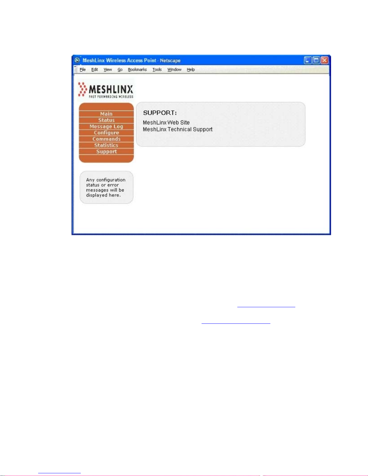
Figure 4.32 Support Window
MeshLinx MWI-5000 User Guide
5.0 Trouble Reporting
Trouble reporting is done via the MeshLinx Web site. At www.meshlinx.com, click
Technical Support. After supplying your username and password, click Ticket to
fill out a trouble ticket, or the email address ([email protected]) to send the
report in an email.
6.0 Specifications
This section provides technical specifications for the MeshLinx MWI-5000
System.
MESHLINX CONFIDENTIAL 8
Page 82

MeshLinx MWI-5000 User Guide
Table 6.3 Electrical and Mechanical Specifications
Electrical
Coverage
Frequency Range
Gain
VSWR
Halfpower Beamwidth (±4°)
Side Lobe Level
Front-to-Back Ratio
Port-to-Port Isolation
Polarization
Diversity
Maximum Input Power
Mechanical
Connectors
Material
Three 60° beams covering 360°
ISM-band (extended), 2.39 GHz to 2.5 GHz
7dBi
<2.5:1 over the entire band
Horizontal: 60°
Vertical: 70°
>20dB below main lobe
>25dB
>50dB
Linear vertical
Dual, vertical spatial
10 watts
SMB Female (12)
Reflector: Aluminum
Radome: n/a
Overall Dimensions
Weight (Indoor Version)
10.33” H × 16.0” Diameter (26cm × 40.6cm)
4.55 lbs (2.1 kg)
6.1 Reference Design
The MeshLinx MWI-5000 System is compliant with all applicable standards
including 802.11b, 802.11g, 802.11a, 802.3 PHY (10/100Mbit/s), 802.3af, JTAG,
and mini-PCI v1.0.
Power Supply Interface includes:
• Power Over Ethernet (POE) using 10/100 FE Interface, or
• Optional—AC Power Supply Interface
• Supports +3.3V Power requirements for SOC-RDP system
• Supports +1.5V for low power devices.
10/100 Fast Ethernet Controller (MAC/PHY) Interface supports:
• External 10/100 signaling
MESHLINX CONFIDENTIAL 8
Page 83

MeshLinx MWI-5000 User Guide
• Single integrated MAC/PHY device in a single package
• Auto-negotiation and parallel detection
• 10/100 BaseT Transformer with POE hooks
• Standard RJ45 Modular Jack
7.0 Configurable Parameters
This section provides details of the configurable parameters that are accessible through
either the CLI or HTTP user interfaces. It focuses on the effects of the parameters and
why one would want to change them.
Each configurable parameter has an associated API function that provides access to
modify it. Both the CLI and HTTP methods of changing a particular parameter access the
same API function. The user interfaces are different (see preceding sections on CLI and
HTTP) but the underlying mechanisms are t h e same.
7.1 Wireless Sectors (interfaces)
The term sector in the MWI-5000 product represents a wireless interface consisting of
radio, base-band and MAC components. Wireless sector and wireless interface are used
interchangeably to describe the same thing.
The MWI-5000 production product has three or more wireless interfaces, each of which
can function as a physical AP.
Each of the three interfaces has a number of configurable parameters that can impact
operation of the radio, base-band or MAC components. The use of each parameter is
discussed below. See the CLI or HTTP sections for information on setting parameters.
7.1.1 MAC Address
The MAC address for each wireless interface can be changed to suit the needs of a
particular user and/or site. Although the MWI-5000 factory default configuration
provides unique MAC addresses for the Ethernet interface and all wireless interfaces, the
user may override these with lo cally-administered MAC addresses or with MAC
addresses prefixed with a user-specific OUI.
There is no need for a user to change the MAC address. It is entirely optional.
MESHLINX CONFIDENTIAL 8
Page 84

MeshLinx MWI-5000 User Guide
7.1.2 Mode
Each wireless interface may be set to operate in one of four 802.11 modes, 11A, 11B,
11BG and 11G. Switching modes may have side-effects that must be anticipated. For
example, switching from 11A to 11B causes the selection of a new default channel
appropriate to that mode. More on this under each mode discussed below.11A Mode
11A mode selects the 5 GHz band (channels 36, 40, 44, 48 etc). The 5 GHz band has the
advantages of less interference than the 2.4 GHz band, more channels to choose from and
data rates up to 54 Mbps. Setting the mode of a wireless interface to 11A restricts
associations on that interface to stations operating in 11A mode.
One disadvantage of 11A mode is the regulatory domain specific restrictions on operating
in the presence of radar signaling. In the US, Europe and Australia, it is a requirement to
immediately vacate certain channels where known radar signatures are detected. The sets
of channels to be concerned about are 52 – 64 (US and Europe) and 100 – 140 (Australia,
parts of Europe and soon to be US).
The MWI-5000 will automatically monitor for known radar signatures when Spectrum
Management is enabled (see discussion of this parameter below). If radar signatures are
detected, the MWI-5000 will switch to a radar-free channel. The process of switching
channels may disrupt the quality of time-sensitive services like voice. Since radar
avoidance is required by law (see the 802.11h standard and associated FCC and ETSI
documents), this potential disruption is unavoidable when operating in affected channels.
7.1.2.1 11B Mode
11B mode selects the 2.4 GHz band (channels 1 through 11). The 2.4 GHz band is
considerably more congested than the 5 GHz band and is limited to data rates up to 11
Mbps. Setting the mode of a wireless interface to 11B restricts associations on that
interface to stations operating in 11B mode.
Select 11B mode when the BSS needs to support only 11B stations and not 11G stations.
7.1.2.2 11BG Mode
11BG mode selects the 2.4 GHz band (channels 1 through 11) in “mixed” mode. The 2.4
GHz band is considerably more congested than the 5 GHz band and is limited to data
rates up to 11 Mbps for 11B stations and 54 Mbps for 11G stations.
Note that the overall throughput for a station operating in mixed mode may be
significantly lower, due to 11G protection mode (self-CTS). 11G protection mode adds
some overhead to 11G transmissions to prevent them from impacting legacy 11B traffic.
The MWI-5000 (and participating 11G stations) automatically engage this mode when
MESHLINX CONFIDENTIAL 8
Page 85

MeshLinx MWI-5000 User Guide
required. The result of engaging protection mode is that the performance of 11G stations
is substantially reduced. See the discussion of self-CTS for more information.
Select 11BG mode when the BSS needs to support both 11B and 11G stations.
7.1.2.3 11G Mode
11G mode selects the 2.4 GHz band (channels 1 through 11) in “pure G” mode. The 2.4
GHz band is considerably more congested than the 5 GHz band and is limited to data
rates up to 54 Mbps.
Note that “pure G” mode assumes there are no 11B stations operating in the BSS and that
protection mode (self-CTS) is not required. This allows the interface to operate at optimal
efficiency, achieving throughput similar to 11A mode in the 5 GHz band. This of course
will depend on local interference in the selected channel.
Select 11G when the BSS needs to support only 11G stations and not 11B stations.
7.1.3 Channel
Selection of a particular mode results in selection of a default channel for that mode.
Depending on interference and congestion in that default channel, it may or may not yield
optimal performance. Manually selecting a new channel is experimental at best. You can
simply try another channel and see if your throughput improves. Avoiding channel 6 in
the 2.4 GHz band is a good idea, since many access points default to that channel and it
tends to be congested.
If the Listen + Learn feature is enabled, the process of channel selection is continuous
and fully automatic. The MWI-5000 monitors for interference in all channels and either
stays on the current channel or switches channels if overall performance would benefit
from the switch. Needless to say, enabling Listen + Learn is recommended over manual
channel selection.
7.1.4 Self-CTS (11G Protection Mode)
11G Protection Mode is automatically enabled whenever both 11G and 11B stations
interoperate within a BSS. The 802.11g standard requires that this be fully automatic.
Turning 11G Protection Mode off is an option for 11G (“pure G”) mode if the user
wishes to completely eliminate the possibility that use of self-CTS is adversely affecting
11G throughput (for benchmarking, etc).
There is no need for a user to change this parameter. It is entirely optional and probably
better avoided.
MESHLINX CONFIDENTIAL 8
Page 86

MeshLinx MWI-5000 User Guide
7.1.5 Transmit Power
The Transmit Power setting determines the power level in dBm that frames will be
transmitted at. The Transmit Power level must be carefully balanced with the Maximum
Data Rate to avoid distortion. For example, setting the Transmit Power to 25 dBm with
the Maximum Data Rate at 54 Mbps will likely result is distortion and therefore failed
attempts to transmit. Lowering either the Transmit Power or the Maximum Data Rate will
eliminate the distortion, thus a Transmit Power of 25 dBm will work much better with a
Maximum Data Rate of 48 Mbps or 36 Mbps.
If the user wishes to elevate the Transmit Power in order to reach a distant station, it is
likely that the Maximum Data Rate will need to be lowered to avoid distortion.
Normally, this parameter should not be adjusted by the user as it is overridden by the
default Automatic Transmit Power Adjustment setting. See the section on Automatic
Transmit Power Adjustment for more information.
7.1.6 Automatic Transmit Power Adjustment
The Automatic Transmit Power Adjustment parameter determines behavior of the MWI5000 device driver with respect to transmit power limitation. It defaults to a setting of
Max54, which ensures that the device driver will never transmit a frame with a transmit
power level too high for the data rate. This setting overrides the Transmit Power value in
dBm.
It is recommended that this parameter be set to Max54 and not modified by the user, as
doing so guarantees the MWI-5000 will never transmit a distorted frame due to an
excessive transmit power level (optimizes range and throughput together).
If the Listen + Learn feature is enabled, the process of transmit power adjustment is
continuous and fully automatic. The MWI-5000 monitors all channels and adjusts its
transmit power to accommodate nearby MWI-5000 access points. Needless to say,
enabling Listen + Learn is recommended over manual Transmit Power selection.
7.1.7 Digital Pre-distortion
Digital Pre-distortion is a MeshLinx-proprietar y feature that improves transmit efficiency
when used with certain radios. For the Maxim radio in the MWI-5000 production
hardware, this parameter has no effect. Future versions of the MWI-5000 hardware may
use radios where this parameter does have effect and this document will be updated to
advise its use.
MESHLINX CONFIDENTIAL 8
Page 87

MeshLinx MWI-5000 User Guide
7.1.8 Sensitivity
The receive sensitivity parameter determines how sensitive a wireless interface radio is to
low-energy signals. A low-energy signal could be a distant station that is legitimately
trying to associate with the MWI-5000 AP or it could be cross-interface interference from
another wireless interface on the same MWI-5000 mini-PCI board.
The sensitivity parameter is set to “high” by default, to ensure that distant stations are
“heard” by the MWI-5000. If it is known that all stations needing network access through
the MWI-5000 are relatively close the receive sensitivity can be set to “medium” or
“low”.
The only reason to set sensitivity to anything but “high” is to avoid cross-inter face
interference between wireless interfaces on the same MWI-5000 mini-PCI board. This
might occur if you are running two or three interfaces in the same mode (e.g. 11G) and
on adjacent channels.
Sensitivity is an advanced tuning parameter that normally does not need to be changed
from its default “high” setting. Avoid changing it unless you suspect cross-interface
interference between two or more interfaces on your MWI-5000 board.
7.1.9 Maximum Data Rate
The maximum data rate parameter limits the data rate used on a MWI-5000 interface. It
defaults to the maximum rate allowed for an operating mode (e.g. 54 Mbps for 11A and
11G, 11 Mbps for 11B). The maximum data rate is used in the MWI-5000 software’s
auto-rate-adjusting algorithm and is the maximum rate that the software will adjust to
when up-rating.
There is typically no need to modify the maximum data rate, except for a situation where
high transmit power levels are required to reach distant stations. In this case, a data rate
of 54 Mbps might not be achievable at a high power level like 20 dBm (due to distortion)
and the maximum data rate should be set to something lower like 48 Mbps or 36 Mbps.
Note that the MWI-5000 software’s auto-rate-adjusting algorithm will work around a
problem with high transmit power by retransmitting at a lower data rate when a higher
data rate fails. Although this works, it is not as efficient as avoiding the failing data rate
altogether. In cases where the transmit power needs to be set higher than normal to reach
distant stations, it may be necessary and will be more efficient to reduce the maximum
date rate to account for the potential distortion at the default maximum data rate.
See the discussion of transmit power for more information.
MESHLINX CONFIDENTIAL 8
Page 88

MeshLinx MWI-5000 User Guide
7.1.10 Diversity
Diversity controls the use of antennas on the MWI-5000. Each wireless interface has a
primary antenna (Antenna 1, default) and a secondary antenna (Antenna 2). Either of
these antennas can be selected manually for an interface. The setting applies to both
receive and transmit operations.
Setting Diversity to Both causes the device driver to al ternately try each antenna,
eventually settling on the antenna that yields the best performance.
For transmit (using Both), the preferred antenna setting is maintained on a per-station
basis and attempts to transmit to a station are tried first using the preferred antenna from
the last transmission.
For receive (using Both), the antenna setting is mostly driven by the transmit diversity
algorithm (transmit diversity trumps receive diversity). When there is little transmit
activity to drive diversity, the receive diversity algorithm selects an antenna that has the
highest RSSI for all stations combined. Typically, it is not the case that traffic will be
mostly receive traffic and most of the time, diversity will be driven by the transmit
algorithm.
The need to modify this parameter is site-dependent. Some users may find that setting
Diversity to Both yields better overall performance for all stations. Other users may find
that best performance is achieved by selecting a particular antenna. The best way to
establish this is to experiment with the three settings, measure the performance yield of
each setting and make a decision based on those results.
7.1.11 Header (preamble)
The Header parameter determines the default preamble type that the MWI-5000 MAC
will use to transmit in 11B mode. It has no meaning in OFDM modes (11G or 11A).
In 11B mode, a longer preamble allows the receiving side greater time to synch-up on the
incoming frame (144 microseconds for long, 72 microseconds for short). The MWI-5000
will receive 11B frames that are transmitted by a station with either long or short
preamble and will respond to (acknowledge) received frames using the same preamble
length as the received frame. To summarize:
• The header parameter is specifi c to 11B mode
• It determines only how the MWI-5000 will transmit 11B frames
• It takes 72 microseconds longer to transmit a 11B frame with a long preamble
• Using long preamble may achieve greater interoperability with legacy 11B
stations
MESHLINX CONFIDENTIAL 8
Page 89

MeshLinx MWI-5000 User Guide
7.1.12 Beacon Interval
The Beacon Interval is the period in milliseconds between beacon transmissions in a
BSS. This parameter can be adjusted higher or lower as a user requires, however
adjusting it to too high a value may cause stations to disassociate (station-dependent).
This is set to 100 milliseconds by default and the user should not need to modify it.
7.1.13 Fragmentation
The Fragmentation parameter determines whether or not the MWI-5000 MAC will
fragment frames into smaller pieces, as indicated by the Fragmentation Threshold
parameter. Typically, fragmentation is done to ensure that frames are transmitted cleanly
on the first try, by reducing the number of continuous bits transmitted and thereby the
likelihood of a transmission error.
Fragmentation overhead is significant, due to the acknowledgement required for every
fragment (as opposed to a single acknowledgement for the complete frame). Typically,
modern auto-rating algorithms obviate fragmentation . . . although there may be extreme
cases where better throughput could be achieved using fragmentation. Users in this
situation probably have a serious problem in their network that needs correcting first.
Normally, this parameter should not be modified by the user and should only be modified
either as an experiment or by a wireless expert who has determined that fragmentation
will solve a specific problem he’s experiencing.
7.1.14 RTS/CTS
The RTS/CTS parameter determines whether or not the MWI-5000 MAC will initiate an
RTS/CTS sequence preceding transmission of certain data frames, as indicated by the
RTS/CTS Threshold parameter. Typically, RTS/CTS exchanges are done to ensure the
medium is clear prior to transmitting data. Often, this is done to avoid the so-called
“hidden node problem”.
RTS/CTS overhead is significant, due to the RTS and CTS transmission times and the
SIFS times between them.
Normally, this parameter should not be modified by the user and should only be modified
either as an experiment or by a wireless expert who has determined that use of RTS/CTS
will solve a specific problem he’s experiencing (such as the hidden node problem).Sector
(interface) Operating Mode
MESHLINX CONFIDENTIAL 8
Page 90

MeshLinx MWI-5000 User Guide
This parameter should be left at the “Normal” setting, unless there is a specific need to
use the interface for spectrum analysis. Note that setting this parameter to Basic Spectrum
Analyzer disables all access point functionality previously running on that interface.
8.0 Glossary
802.11: 802.11 is a family of specifications for Wireless Local Area Networks
(WLANs) developed by a working group of the Institute of Electrical and
Electronics Engineers (IEEE). The original specification provides for an Ethernet
Media Access Controller (MAC) and several physical layer (PHY) options, the
most popular of which uses GFSK modulation at 2.4GHz, enabling data rates of 1
or 2Mbps. Since its inception, two major PHY enhancements have been adopted
and become “industry standards”. 802.11b adds CCK modulation enabling data
rates of up to 11Mbps, and 802.11a specifies OFDM modulation in frequency
bands in the 5 to 6GHz range, and enables data rates up to 54Mbps.
AICS: Automatic Intelligent Channel Selection is the capability for the Access
Point to select best channel based on the RF environment conditions.
ATPC: Automatic Transmit Power Control is the capability for the Access Point to
select best transmit power based on the RF environment conditions.
Authentication: The process of establishing the identity of another unit (client,
user, device) prior to exchanging sensitive information.
Bluetooth: An open specification for short-range wireless voice and data
communication. Bluetooth is a trademark owned by Telefonaktibolaget L M
Ericsson, Sweden, and licensed to promoters and adopters of the Bluetooth Special
Interest Group (SIG).
DFS: Dynamic frequency selection refers to the radar avoidance algorithm
referred by 802.11h amendment.
DHCP: Dynamic Host Configuration Protocol (DHCP) is a communications
protocol that lets network administrators centrally manage and automate the
assignment of Internet Protocol (IP) addresses in an organization's network. Using
the Internet Protocol, each machine that can connect to the Internet needs a unique
IP address. When an organization sets up its computer users with a connection to
the Internet, an IP address must be assigned to each machine. Without DHCP, the
IP address must be entered manually at each computer and, if the computer moves
to another location in another part of the network, a new IP address must be
entered. DHCP lets a network administrator supervise and distribute IP addresses
from a central point and automatically sends a new IP address when a computer is
plugged into a different place in the network.
DNS: Domain Name Service. An Internet service that translates a domain name
such as example-systems.com to an IP address, in the form xx.xx.xx.xx, where xx
is an 8 bit hex number.
MESHLINX CONFIDENTIAL 9
Page 91

MeshLinx MWI-5000 User Guide
EIRP: The Effective Isotropic Radiated Power of a t ransmitter is the power that the
transmitter appears to have if the transmitter’s antenna was an isotropic radiator,
i.e., if it radiated equally in all directions. By virtue of the gain of a radio antenna—
omni-directional or directed—or a dish, a beam is formed that preferentially
transmits the energy in one direction. The EIRP is determined from the product of
the gain and the transmitter power.
Ethernet: Ethernet is the most widely installed local area network (LAN)
technology. Specified in a standard, IEEE 802.3, Ethernet was originally developed
by Xerox and then developed further by Xerox, DEC, and Intel. An Ethernet LAN
typically uses coaxial cable or special grades of twisted-pair wires. Ethernet is also
used in wireless LANs. The most commonly installed Ethernet systems are called
10-BaseT and provide transmission speeds up to 10Mbps. Devices are connected to
the cable and compete for access using a Carrier Sense Multiple Access with
Collision Detection (CSMA/CD) protocol.
Fast Ethernet or 100-BaseT provides transmission speeds up to 100Mbps and is
typically used for LAN backbone systems, supporting workstations with 10-BaseT
cards. Gigabit Ethernet provides an even higher level of backbone support at
1000Mbps (1 gigabit or 1 billion bits per second). 10Gbps Ethernet provides up to
10 gigabits per second.
HTTP: The Hypertext Transfer Protocol (HTTP) is a set of rules for exchanging
files (text, graphic images, sound, video, and other multimedia files) on the World
Wide Web. Relative to the TCP/IP suite of protocols (which are the basis for
information exchange on the Internet), HTTP is an application protocol.
Hub: In data communications, a hub is a place of convergence where data arrives
from one or more directions and is forwarded out in one or more other directions. A
hub usually includes a switch of some kind. (And a product that is called a "switch"
could usually be considered a hub as well.) The distinction seems to be that the hub
is the place where data comes together and the switch is what determines how and
where data is forwarded from the place where data comes together. Regarded in its
switching aspects, a hub can also include a router.
IEEE: Institute of Electrical and Electronics Engineers. The IEEE describes itself
as the world’s largest professional society. The IEEE fosters the development of
standards that often become national and international standards, such as 802.11.
IP: The Internet Protocol (IP) is the method or protocol by which data is sent from
one computer to another on the Internet. Each computer (known as a host) on the
Internet has at least one IP address that uniquely identifies it from all other
computers on the Internet. When you send or receive data (for example, an e-mail
note or a Web page), the message gets divided into little chunks called packets.
Each of these packets contains both the sender's Internet address and the receiver's
address. Any packet is sent first to a gateway computer that understands a small
part of the Internet. The gateway computer reads the destination address and
forwards the packet to an adjacent gateway that in turn reads the destination
address and so forth across the Internet until one gateway recognizes the packet as
belonging to a computer within its immediate neighborhood or domain. That
MESHLINX CONFIDENTIAL 9
Page 92

MeshLinx MWI-5000 User Guide
gateway then forwards the packet directly to the computer whose address is
specified.
ISP: An ISP (Internet Service Provider) is an entity that provides individuals and
companies access to the Internet and other related services such as Web site
building and hosting. An ISP has the equipment and the telecommunication line
access required to have a Point-of-Presence (PoP) on the Internet for the geographic
area served.
LAN: A Local Area Network (LAN) is a group of computers and associated
devices that share a common communications line and typically share the resources
of a single processor or server within a small geographic area (for example, within
an office building). Usually, the server has applications and data storage that are
shared in common by multiple computer users. A local area network may serve as
few as two or three users (for example, in a home network) or as many as
thousands of users (for example, in an FDDI network).
MAC: Medium Access Control. In a WLAN network card, the MAC is the radio
controller protocol. It corresponds to the ISO Network Model's level 2 Data Link
layer. The IEEE 802.11 standard specifies the MAC protocol for medium sharing,
packet formatting and addressing, and error detection.
OFDM: Orthogonal Frequency-Division Multiplexing (OFDM) is a method of
digital modulation in which a signal is split into several narrowband channels at
different frequencies. The technology was first conceived in the 1960s and 1970s
during research into minimizing interference among channels near each other in
frequency.
In some respects, OFDM is similar to conventional frequency-division
multiplexing (FDM). The difference lies in the way in which the signals are
modulated and demodulated. Priority is given to minimizing the interference, or
crosstalk, among the channels and symbols comprising the data stream. Less
importance is placed on perfecting individual channels.
RADIUS: Remote Authentication Dial-In User Service (RADIUS) is a
client/server protocol and software that enables remote access servers to
communicate with a central server to authenticate dial-i n (or other temporarily
connected) users and authorize their access to the requested system or service.
RADIUS allows a company to maintain user profiles in a central database that all
remote servers can share. It provides better security, allowing a company to set up a
policy that can be applied at a single administered network point. Having a central
service also means that it's easier to track usage for billing and for keeping network
statistics.
Router: On the Internet, a router is a device or, in some cases, software in a
computer, that determines the next network point to which a packet should be
forwarded toward its destination. The router is connected to at least two networks
and decides which way to send each information packet based on its current
understanding of the state of the networks it is connected to. A router is located at
MESHLINX CONFIDENTIAL 9
Page 93

MeshLinx MWI-5000 User Guide
any gateway (where one network meets another), including each Internet point-ofpresence. A router is often included as part of a network switch.
Routing is a function associated with the Network layer (layer 3) in the standard
model of network programming, the Open Systems Interconnection (OSI) model. A
layer-3 switch is a switch that can perform routing functions.
RRM: Radio Resource Measurement (RRM) refers to 802.11k amendment.
SDMA: Spatial Division Multiple Access (SDMA) is a communications mode that
optimizes the use of the radio spectrum and minimizes the system cost by taking
advantage of methods to segment geographic areas.
SIFS: Short Inter-Frame Space are found in IEEE 802.11 networks. Employed for
the highest priority transmissions that enables stations with this type of
SNMP: Simple Network Management Protocol (SNMP) is the protocol governing
network management and the monitoring of network devices and their functions. It
is not necessarily limited to TCP/IP networks.
SNMP is described formally in the Internet Engineering Task Force (IETF)
Request for Comment (RFC) 1157 and in a number of other related RFCs.
Switch: In telecommunications, a switch is a network device that selects a path or
circuit for sending a unit of data to its next destination. A switch may also include
the function of the router, a device or program that can determine the route and
specifically what adjacent network point the data should be sent to. In general, a
switch is a simpler and faster mechanism than a router, which requires knowledge
about the network and how to determine the route.
Relative to the layered Open Systems Interconnection (OSI) communication model,
a switch is usually associated with layer 2, the Data-Link layer. However, some
newer switches also perform the routing functions of layer 3, the Network layer.
Layer 3 switches are also sometimes called IP switches.
TCP: Transmission Control Protocol (TCP) is a set of rules (protocol) used along
with the Internet Protocol (IP) to send data in the form of message units between
computers over the Internet. While IP handles the actual delivery of the data, TCP
keeps track of the individual units of data (called packets) that a message is divided
into for efficient routing through the Internet.
TCP is a connection-oriented protocol, which means that a connection is
established and maintained until such time as the message or messages to be
exchanged by the application programs at each end have been exchanged. TCP is
responsible for ensuring that a message is divided into the packets that IP manages
and for reassembling the packets back into the complete message at the other end.
In the Open Systems Interconnection (OSI) communication model, TCP is in layer
4, the Transport Layer.
TCP/IP: Transmission Control Protocol/Internet Protocol(TCP/IP) is the basic
communication language or protocol of the Internet. It can also be used as a
communications protocol in a private network (either an intranet or an extranet).
When you are set up with direct access to the Internet, your computer is provided
MESHLINX CONFIDENTIAL 9
Page 94

MeshLinx MWI-5000 User Guide
with a copy of the TCP/IP program just as every other computer that you may send
messages to or get information from also has a copy of TCP/IP.
TCP/IP is a two-layer program. The higher layer, Transmission Control Protocol,
manages the assembling of a message or file into smaller packets that are
transmitted over the Internet and received by a TCP layer that reassembles the
packets into the original message. The lower layer, Internet Protocol, handles the
address part of each packet so that it gets to the right destination.
Telnet: Telnet is the way to access someone else's computer, assuming they have
given permission. (Such a computer is frequently called a host computer.) More
technically, Telnet is a user command and an underlying TCP/IP protocol for
accessing remote computers. On the Web, HTTP and FTP protocols allow you to
request specific files from remote computers, but not to be actually logged on as a
user of that computer.
TKIP: The Temporal Key Integrity Protocol, pronounced tee-kip, is part of the
IEEE 802.11i encryption standard for wireless LANs. TKIP is the next generation
of WEP, the Wired Equivalent Privacy, which is used to secure 802.11 WLANs.
TKIP provides per-packet key mixing, a message integrity check, and a re-keying
mechanism, thus fixing the flaws of WEP.
WEP: Wired Equivalent Privacy is the built-in baseline security protocol that is
rolled into the 802.11b protocol. WEP is disabled by default in most shipping
WLAN hardware, showing that vendors have never particularly had confidence in
WEP and have assumed security would be deployed as a basic WLAN
functionality by customers. WEP inhibits raw throughput at a ratio of about 50%.
WiFi: WiFi is another name for IEEE 802.11b. It is a trade term promulgated by
the Wireless Ethernet Compatibility Alliance (WECA). "WiFi" is used in place of
802.11b in the same way that "Ethernet" is used in place of IEEE 802.3. Products
certified as WiFi by WECA are interoperable with each other even if they are from
different manufacturers. A user with a WiFi product can use any brand of access
point with any other brand of client hardware that is built to the WiFi standard.
Contrary to popular belief, “WiFi” does not stand for “wireless fidelity.” WECA
chose the term WiFi as a catchy term similar to the term HiFi. Unlike HiFi,
however, WiFi has no parent phrase.
WLAN: A Wireless Local Area Network (WLAN) is one in which a mobile user can
connect to a LAN through a wireless (radio) connection. The IEEE standard, 802.11,
specifies the technologies for WLANs. The standard includes an encryption method, the
WEP algorithm.
MESHLINX CONFIDENTIAL 9
 Loading...