

Page 1

MD4000 Product Family
Hardware Installation Instructions
HWIG Version 0306 © 2002-2007 Meshdynamics, Inc. All rights Reserved. Proprietary Information. Patents Pending
1
Page 2
Terminology
Wireless
Backhaul
RELAY 1
Ethernet
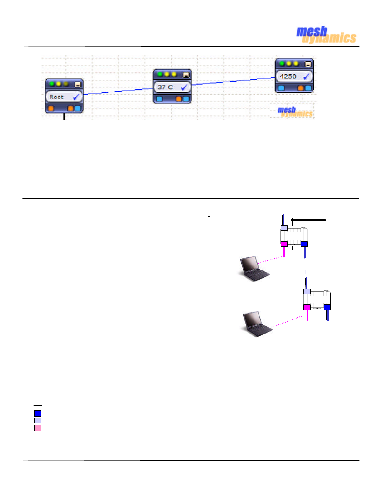
Root and Relay Nodes
Mesh Networks provide long range connectivity by relaying packets from one mesh node to another,
like a bucket brigade. The end of the bucket brigade terminates at the root – which connects to the
Ethernet. (above) Relays connect to the root or other relay nodes to form a wirelessly linked chain.
Upstream & Downstream
Upstream implies closer to the Ethernet. The root is upstream of relay 1.
Wireless Uplinks and Downlinks. The Ethernet link is the uplink
(upstream link) connection for the root. The root has is a wired uplink.
Its “backhaul” is the wired network.
Relays have wireless uplinks through a upstream downlink radio.
Downlink radios act like Access Points (AP) : they send out a beacon.
Uplink radios act like clients – they do not send out a beacon.
A wireless radio card in the laptop can inform you of the presence of
downlinks but not of uplinks. Downlinks beacon, Uplinks do not.
RELAY 2
Ethernet
ROOT
DOWNLINK
UPLINK
The uplink and downlink radios form a wireless backhaul path.
AP radios operate in the 2.4GHZ band to service 11b/g clients.
802.11a wireless devices may be serviced by the 5.8G downlink.
SERVICE
RELAY
Thus, both 802.11a and 802.11b/g client access is supported.
Backhaul radios operate in 5.8GHZ band to avoid interference with
the 11b/g 2.4GHZ AP radio (shown pink, right). Note: Do not use
any other modules not approved with this device other
then the ones that were tested which are MD2 FCC ID:
UZU-MD2 and MD5 FCC ID: UZU-MD5
To summarize, there are 4 types of “links” to Structured Mesh
A wired uplink to provide Ethernet connectivity. This connects the Root node to the wired network.
A wireless downlink to provide wireless connectivity. Acts like an AP for the uplink. Typically 5.8G.
A wireless uplink to connect to upstream mesh nodes. This is a “client” to the downlink. Typically 5.8G.
A AP radio for clients. Typically 2.4G with support for both b and g clients.
In our standard offering, the 11a uplink, the 11a downlink and 11b/g service are 3 separate radios (Fig 2.2).
HWIG Version 0306 © 2002-2007 Meshdynamics, Inc. All rights Reserved. Proprietary Information. Patents Pending
TM
products:
2
Page 3

The MD 4000 Product Family
The MD4000 Modular MeshTM products support up to 4 radios in a single enclosure.
Slots 0, 1 house one uplink and one downlink radio operating on non-interfering
channels but in the same frequency band. They are both 2.4G or both 5.8G. radios.
Note: Do not use any other modules not approved with this device other then the ones
that were tested which are MD2 FCC ID: UZU-MD2 and MD5 FCC ID: UZU-MD5
Note: This two radio backhaul differs from competing mesh products. The differences are explained
at: www.meshdynamics.com/WhyStructuredMesh.html
Slot 2 houses a 2.4G AP radio for client connectivity. 2.4G radios can be set to b. b and g or g only
modes. Slot 3 can house a 2nd downlink, 2nd AP or a scanning radio for mobile mesh module - that
form part of the meshed backhaul in dynamic infrastructure mesh networks.
The 2 Ethernet ports on each module may be used to interface to cameras for high resolution video
over mesh. A 2nd (slave) module attaches via Ethernet to provide a total of 8 radios. Operating
temperature range is -40 to +85 Celsius. The die cast weather proof enclosure is NEMA 67 rated.
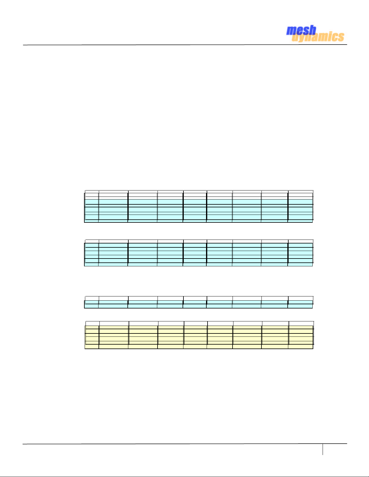
2.4G Backhaul Products (Standard Configurations)
0 3
0 3
0
3
Uplink
Downlink
Service
2.4G 5.8G
2 1
MD4220 MD4320 MD4325
1. MD4220-BBxx: 2-Radio module 2.4G uplink and downlink Backhaul (BH). .
2. MD4320-BBBx: 3-Radio module 2.4G sectored BH slots 0,1 and 2.4G AP radio in slot 2.
3. MD4325-BBxB: 3-Radio module 2.4G BH, Downlink also acts as AP. A 2.4G Mobility Scanner in slot 3.
2 1
2
1
Scanner
5.8G Backhaul Products (Standard Configurations)
0
2
MD4250 MD4350 MD445 MD4458 MD4455
1. MD4250-AAxx: 2-Radio module 5.8G BH uplink and downlink Backhaul (BH).
2. MD4350-AABx: 3-Radio module 5.8G BH and 2.4G AP radio in slot 2. AP modes may be b, g, or b & g.
3. MD4452-AABA: 4-Radio module 5.8G BH and 2.4G AP radio. Second sectored 5.8G downlink in slot 3.
4. MD4458-AABB: 4-Radio module 5.8G BH and 2.4G AP radios (two) in slots 2, 3 for sectored service.
5. MD4455-AABA: 4-Radio module 5.8G BH and 2.4G AP radio in slot 2. 5.8G Scanner in slot 3
3
1
0
2
3
1
0 3
2 1
0 3
2 1
0
2
3
1
Notes:
1. All 2.4G Downlinks and APs may be configured to support b only, g only, or b & g client connectivity
2. All 5.8G Downlinks may be configured to provide 802.11a client connectivity
3. All radios interfaces may be configured to provide IEEE 802.11e differentiated Class of Service
HWIG Version 0306 © 2002-2007 Meshdynamics, Inc. All rights Reserved. Proprietary Information. Patents Pending
3
Page 4
How Far Apart Should Backhaul Radios be Placed?
Case #
For a “good signal”, the fraction of the energy from the transmitter that reaches the receiver should exceed the
receiver radio’s receive sensitivity. If not, the ACK will not be sent and re-transmission occurs. Throughput then
declines. The rate control software on the mesh module is sampling the link quality between its uplink and the
parent downlink. If the throughput declines, it lowers the transmit rate, since transmit power and receive
sensitivity improve at lower transmit rates. The throughput is thus adjusted based on signal quality.
Degradation of signal quality over distance is expressed by the free space path loss relationship:
Path_Loss = 20*log(Freq) + Decay_* 10*log(Dist) – K where
Path_loss: Path Loss in dBm
Freq: Frequency in MHZ
Decay : Varies based on RF environment, line of sight etc.
Dist: Distance between the two mesh nodes (in meters)
K: Constant.
Transmit power from the radio and antenna gains offsets this path loss. The adjusted value must then exceed the
receiving radio receive sensitivity for transmissions to be “heard”. Table A1 shows backhaul distances for a 5.8G
radio transmitting with 20 dBm transmit power radio and over two 8 db omni-directional antennas. Acceptable
receive sensitivity is set at – 65 dBm. Decay is varied from 2.0 (rural, open space) to 2.4 (more urban settings,
non line of sight, occlusions, interference). Notice how range is dramatically affected by changes in Decay.
RS (dBm) TR (dBm) Decay Ant 01 Ant 02 Freq (MHZ) Dst (m) Dst (Ft)
01 65 20 2.0 8 8 5800 461 1512
Table A1
02 65 20 2.2 8 8 5800 264 866
03 65 20 2.4 8 8 5800 166 544
Increasing antenna gain from 8 dBm to a 14 dBm panel on the downlink reduces this path loss (Table A2).
01 65 20 2.0 14 8 5800 921 3017
Table A2
02 65 20 2.2 14 8 5800 495 1622
03 65 20 2.4 14 8 5800 295 967
Panels have a less dispersed beam pattern than omni-directional antennas. Their restricted field of view also
makes them less sensitive to noise in the vicinity. In very noisy settings, more radio transmit power may be
needed. Two downlinks doubles transmit radio power from 20 dBm to 23 dBm. (Table A3).
Table A3
01 65 23 2.4 14 8 5800 394 1290
Range is also effectively doubled by changing from 5.8G to a 2.4G backhaul. Compare Table A4 with Table A1.
01 65 20 2.0 8 8 2400 1115 3655
Table A4
02 65 20 2.2 8 8 2400 589 1931
03 65 20 2.4 8 8 2400 346 1135
Unfortunately, the 2.4G RF space is “polluted” with multiple AP and client devices. 2.4G Backhauls are best limited
to rural areas with low subscriber density and low 2.4G RF interference. If 2.4G Backhauls are critical, reduce 2.4G
RF interference on the backhaul with a panel antenna and its more focused beam. The 4320 3-radio 2.4G
backhaul product is intended to be used with panels on the backhaul and an omni for the 3rd 2.4G AP radio .
Suggestions
In rural areas or low client density situations, use 2.4G backhauls preferably with panels to reduce RF interference
from other 2.4G devices. In all other scenarios use 5.8G Backhauls. Start with two 8 dBm 5.8G omni-directional
250m apart, with clear line of sight and no metal obstructions with 1.5m of the antennas. Increase node spacing
till throughput begins to decline – look at the heart beats shown on the NMS. For noisy 5.8G environments, reduce
path loss with panels and/or double the transmit power with dual downlinks (4452).
HWIG Version 0306 © 2002-2007 Meshdynamics, Inc. All rights Reserved. Proprietary Information. Patents Pending
4
Page 5
How Far Apart Should AP Radios be Placed?
Case #
Case #
RS (dBm) TR (dBm) Decay Ant 01 Ant 02 Freq (MHZ) Dst (m) Dst (Ft)
01 65 20 2.0 8 8 5800 461 1512
Table B1
Table B2
Table B1 and B2 indicate that the range of the 2.4G radios backhaul will always exceed that of the 5.8G backhaul.
The theory does not take into consideration two salient real-world differences between backhauls and AP radios:
1. Antennas are generally mounted on roof tops. The backhaul antennas generally have free space line of sight
connectivity. However the antennas of the AP, also mounted on roof tops, must connect with clients on the ground.
The path from AP antennas to the 2.4G client radios is often not clear line of sight. Additionally, there is significant
2.4G RF interference in urban areas. With higher decay the range is significantly reduced (Table B3).
Table B3
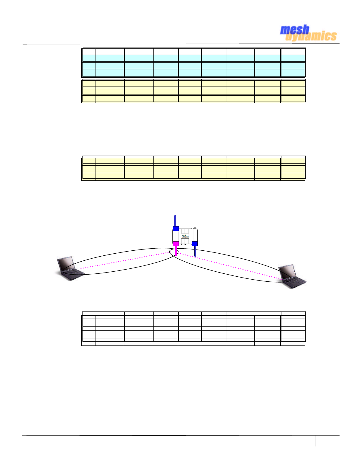
2. Clients on the same AP also can also create RF interference due to Hidden-Node effects. The AP has big ears
(high receive sensitivity). Even though clients radios are much lower power, the AP can hear them. It also has a loud
voice (high transmit power) so clients can hear it. But clients may not be able to hear each other such as when
clients are on opposite ends from each other. The clients are thus “hidden”.
02 65 20 2.2 8 8 5800 264 866
03 65 20 2.4 8 8 5800 166 544
01 65 20 2.0 8 8 2400 1115 3655
02 65 20 2.2 8 8 2400 589 1931
03 65 20 2.4 8 8 2400 346 1135
01 65 20 2.6 8 8 2400 221 724
02 65 20 2.8 8 8 2400 150 492
03 65 20 3.0 8 8 2400 108 352
HIDDEN NODE EFFECT
Fig. 6.1
AP hears both Clients.
But clients do not hear each other.
Radio is a shared medium: only one device should be active at any time. If clients are “hidden” from each other,
then they could be talking at the same time, causing RF interference and loss of signal quality. Table B4 indicates
that clients hear each other only within 100 meters .In noisy or occluded settings it could be as low as 50 meters.
RS (dBm) TR (dBm) Decay Ant 01 Ant 02 Freq (MHZ) D (m) D (Ft)
01 65 15 2.0 0 0 2400 99 326
Table B4
02 65 15 2.2 0 0 2400 65 214
03 65 15 2.4 0 0 2400 46 151
Suggestions
If omni-directional antennas are being used, select ones with down tilt. This focuses the beam downwards – where
the clients. This also reduces the AP range so clients are less spread apart. The hidden node effect is thus curtailed.
For noisy /occluded environments, reduce path loss with panels and/or double transmit power with dual AP radios.
Note: Range Calculation Sheet location: www.meshdynamics.com/DOWNLOADS/MDRangeCalculations.xls
HWIG Version 0306 © 2002-2007 Meshdynamics, Inc. All rights Reserved. Proprietary Information. Patents Pending
5
Page 6
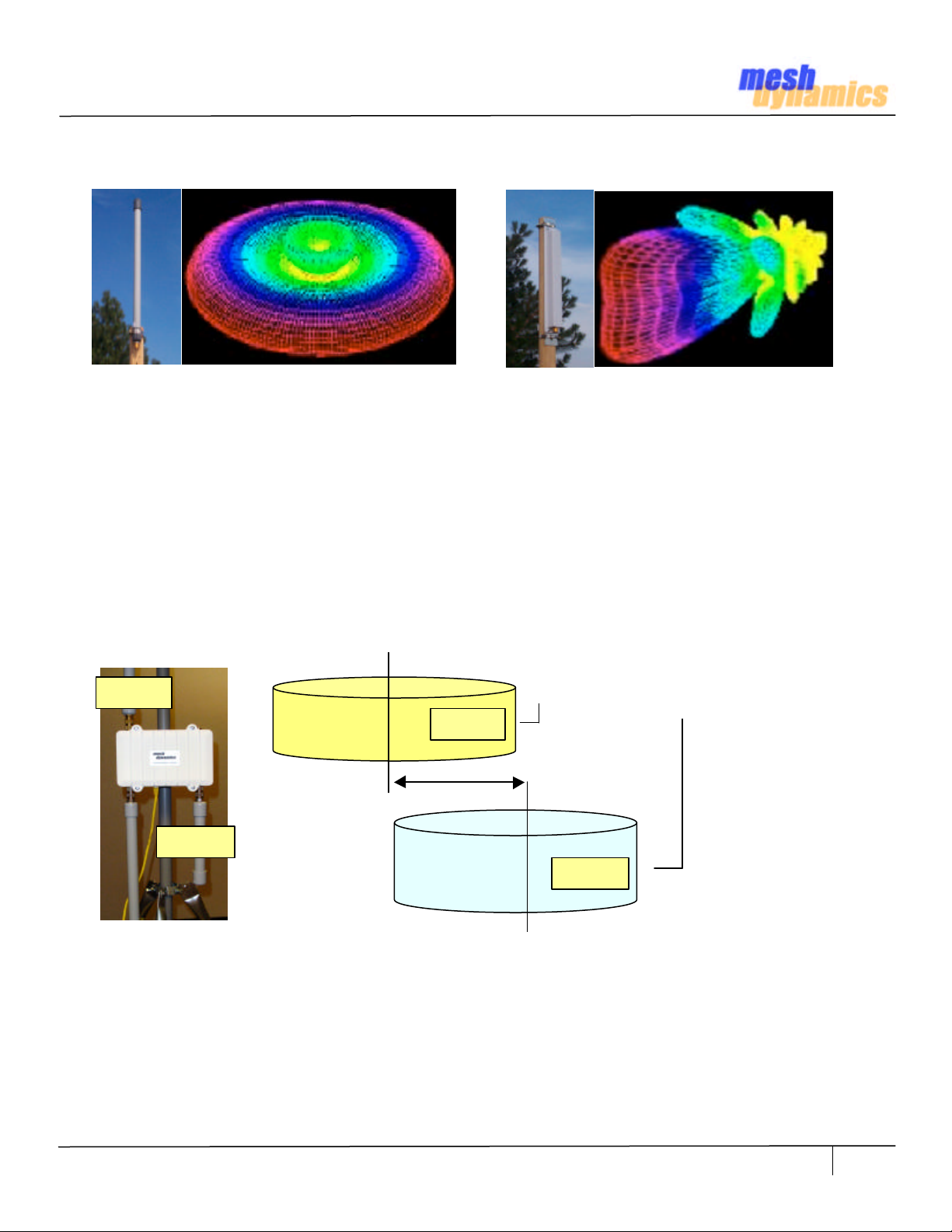
Recommended Antenna Selection and Placement
Omni Directional Doughnut Shape
Figure 6.1
Omni-directional antennas provide an even distribution of RF energy (above, left). Directional antennas, in contrast,
focus RF energy towards a receiver in their line of sight. Omni-directional antennas as less efficient that directional
antennas as distance between the relay increases. In the event the RF signal is weak, over long ranges, Sector or
Panel antennas should be considered.
When ordering omni-directional antennas for the up/down links, look at the down tilt and vertical beam width
specifications. If the relays are at different heights,or differing angles then the RF beams may not “connect”.
The service radio antenna, if omni-directional, should have a large down tilt, if mesh nodes are mounted up high. In
that case the beam has to travel downwards to reach client devices (e.g. laptops) on the ground.
UPLINK
UPLINK
Same Frequency Band
at least 20 cm
Directional Antenna
Vertical
DNLINK
The up-link and down-link antennas operate on the same frequency band – they are either BOTH 11a or 11b/g.
For all antennas, avoid placements where the open end of is near metal poles or near power transformers. Also omni-
directional antennas, should be mounted as vertical as possible and at similar heights for best results. Note at the
down tilt and beam width affects permissible height variations, based on the tangent of the angle times the distance.
NOTE: ANTENNA PLACEMENTS MUST BE ATLEAST 20 CMS APART. SEE PAGE 15, TERMS OF USE
HWIG Version 0306 © 2002-2007 Meshdynamics, Inc. All rights Reserved. Proprietary Information. Patents Pending
Separation
DNLINK
Figure 6.2
6
Page 7
Aligning Omni-directional Antennas
Understanding the beam pattern of omni-directional antennas and the “vertical window of connectivity” that is
available at any given distance is important in the alignment of the antennas for the mesh backhaul, It is especially
important when the terrain for the mesh deployment varies in elevation, and/or the objects on which the mesh
nodes will be mounted vary in height.
An omni-directional antenna has a radiation pattern that looks like a horizontal disc emanating from the antenna.
The disc gradually gets thicker as you move farther from the antenna, and the angle that describes how fast it gets
thicker is called the “vertical beam angle”.
Given that the antennas are mounted perfectly vertical (please use a level to ensure this), there will be a vertical
window at any given distance from a first backhaul antenna within which a second backhaul antenna will be able to
receive signals transmitted with the full rated gain of the first antenna.
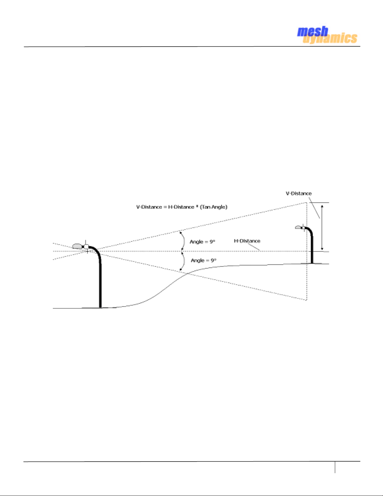
In the diagram below, the 18 degree vertical beam angle shown corresponds to a preferred 8dBi, 5GHz omni
antenna. One can think of this vertical pattern as two right triangles back-to-back where each has a 9 degree angle
- one triangle facing up and one facing down relative to a horizontal line.
Figure 7.1
Here is how the trigonometry works for omni-directional antennas.
The side of each triangle opposite the 9 deg angle (V-Distance) represents the height above and below horizontal
that the antenna’s radiation pattern will cover given that you are some distance away, for instance 800 ft. The
tangent of 9 degrees is 0.158, so at an 800 ft distance, the pattern will cover a height of (800 * 0.158 =126 feet)
above, as well as 126 feet below horizontal for a total vertical window of 252 feet. If however, the antenna on the
first node is tilted only 3 degrees from vertical and tilted in the wrong direction relative to a second node, the
vertical connection window available at the second node is now reduced to that resulting from a 6 degree angle
giving a height of (800 * 0.105 = 84 feet) from horizontal in the direction of interest instead of 126 feet.
As the distance between the mesh nodes grows, the vertical window enlarges. As the distance between mesh nodes
is shortened, the vertical window shrinks. For instance, if for some reason the nodes were placed 300 ft apart, the
connectivity window would be (300 * 0.158 = 47) feet above and 47 feet below. Basically, the further apart the
nodes are, the less sensitive they are to the relative height of the nodes.
HWIG Version 0306 © 2002-2007 Meshdynamics, Inc. All rights Reserved. Proprietary Information. Patents Pending
7
Page 8

Suggested Check List
A
E
F
Figure 8.1
A. Windows 98 or better laptop with PCMCIA card and Ethernet Port Access.
Temporarily disable firewalls on the laptop if you intend to configure the nodes with the NMS
B. 802.11 a/b/g card. Model Shown: SMC 2336 W-ACG. Needed for any remote diagnostics.
C. N-Male to N-Male Barrel Adaptors. Needed to temporarily mount Antennas on Structured MeshTM Module
B
C
G
D
H
D. N-Male to N-Male low loss Cabling. Connects Antennas (E, F) to N-Female Connectors on Module
E. Downlink and Uplink Antennas. Two required. For Backhaul. Typically 11a (5.8G), Full range.
5.8Ghz Omni-directional www.Superpass.com/SPDJ6O.html , www.Superpass.com/SPDJ6OP.html
F. Service 8dBi Antenna for connecting to client devices (e.g. laptops). Typically 11b/g (2.4G).
2.4Ghz Omni-directional: www.Superpass.com/SPDG16O.html , www.Superpass.com/SPDG16OP.html
G. Power Over Ethernet (POE) injector.
Input Voltage 110V, Output 24VDC on Pins 4,5 of Ethernet RJ45 Connector.
Not included with modules but may be purchased separately from Meshdynamics.
H. RJ45 Ethernet Cables. Two needed. One connects to the wired network, the other to the node.
Notes:
1. Items E.F relates to a typical 3-Radio Mesh Module: 11a uplink/downlink and 11b/g service.
If the uplink and downlink or service radio types/settings change, please change antennas accordingly
HWIG Version 0306 © 2002-2007 Meshdynamics, Inc. All rights Reserved. Proprietary Information. Patents Pending
8
Page 9
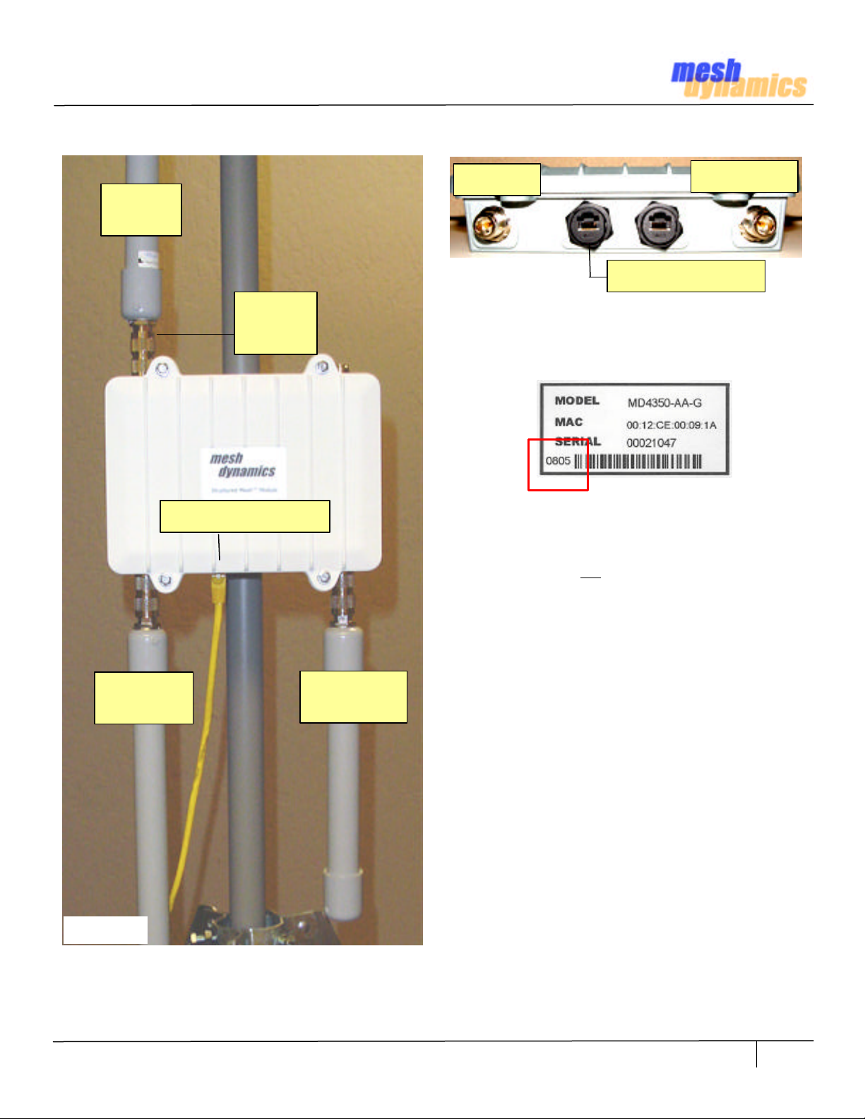
Connecting the Downlink Antennas to the Module
UPLINK
802.11a
N-MALE
BARREL
ADAPTOR
24VDC + Ethernet
SERVICE
.
Figure 9.2
Note: Units built after August 2005 have connections on
the module is shown in Figures 9.1, 9.2
Example: 0805 is the MMYY date of manufacture.
If there is no number on your sticker, then uplink and
downlink connections are reversed. But switching them
also requires opening the module and placing the radios
in different mini-PCI slots, as described later
24VDC + Ethernet
DOWNLINK
Switching to the current convention is advised, but does
not affect performance of the unit. Reversing the uplink
and downlink antennas may require antenna alignments.
SERVICE
802.11b/g
Figure 9.1
Antenna Mounting Shown for illustration Purposes Only.
NOTE: ANTENNAS MUST BE ATLEAST 20 CMS APART. SEE PAGE 15, TERMS OF USE
DOWNLINK
802.11a
HWIG Version 0306 © 2002-2007 Meshdynamics, Inc. All rights Reserved. Proprietary Information. Patents Pending
9
Page 10

Bringing up a ROOT Node
SERVICE
24VDC + Ethernet
Figure 10.1
1. Mount the Antennas as shown on on the previous page.
2. Connect a cable from the switch to the POE injector (above).
3. Verify internet connectivity on the cable to be plugged into the unit.
4. Power up the POE Injector. The LED on the POE will light up.
5. Now connect the Ethernet cable (with power) to the Module.
6. The internal fan should start and is audible, if you put your ear to the box.
7. Insert the 11a/b/g radio card and bring up the Wireless Card utility.
8. Firewalls should be disabled if you wish see the Heartbeats on the NMS.
9. The wireless card utility will show two APs named MESH_INIT and the last numbers of the MAC ID of the
radio, for identification purposes. These are the downlink radio and service radio AP of the root node.
Note: On power up the node first senses if there is an Ethernet link on the first Ethernet port. If it senses one,
it configures itself as a root node. If no Ethernet link is sensed, the node assumes it is a relay. It’s uplink radio
then searches for other mesh node downlinks to connect to. It first searches for a root node, failing which it
searches for a relay node that has established a chained link back to a root node. If there are multiple relay
node candidates, it will connect to the relay that provides the best service, based on test packet transmissions.
DOWNLINK
NMS Running Here
(on same switch)
LED
110VAC
10. If the Ethernet cables are “good” then the Ethernet will be sensed and the MESH_INIT_XX will change to
StructuredMesh (below). If it does not, check the Ethernet cables and connectivity back to the switch.
Fig. 10.2
In the image above, one “AP” is on the 5.8GHZ backhaul frequency band (802.11a). This is the root
downlink radio. The other radio is the 2.4GHZ AP client service on 802.11b/g. Connect the 11a/b/g radio
card to both radios to verify wireless connectivity on both 802.11a and 802.11b/g
HWIG Version 0306 © 2002-2007 Meshdynamics, Inc. All rights Reserved. Proprietary Information. Patents Pending
10
Page 11
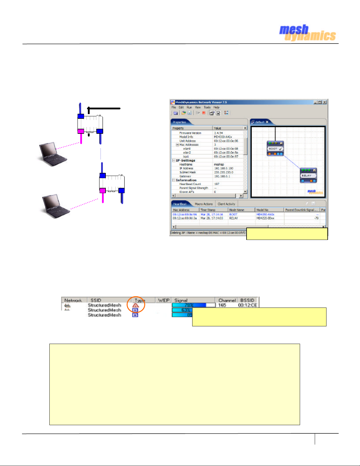
Bringing up a RELAY Node
1. Mount the Antennas as shown on Figure 10.1. Power up the POE Injector. The LED will light up. Power up the
Module. The fan should start and be audible. 4. Bring up the 11a/b/g Wireless Card utility on the laptop.
2. The wireless card utility will show two APs named MESH_INIT and the numbers of the MAC ID of the radio.
These are the downlink radio and service radio AP. In general, the downlink radios searches for other mesh nodes
to connect to. The Service AP also radio scans to select the best non-interfering channels.
Ethernet
ROOT
DOWNLINK
UPLINK
SERVICE
RELAY
Figure 11.1
Heart Beat Status Updates
3. The relay node “scans” until it finds another node (root or upstream relay) to form a backhaul path. If
successful , the MESH_INIT SSID changes to StructuredMesh in 1-2 minutes. If the NMS is running (see NMS
User Guide for details), then the ROOT and RELAY nodes should show up based on heart beats sent by nodes.
4. If the radio does not change from MESH_INIT then check to see if the a/b/g wireless radio card can “see” a
potential parent downlink to connect to. The radio card utility must show at least one 11a downlink (below)
Figure 11.2
If the relay uplink antenna cannot “see” a parent downlink, it cannot “connect” to it! Check if:
• The antenna placement for the uplink and downlink on all nodes are as shown in Fig 9.1
• The node uplink antenna is of the right type for the backhaul frequency band
• The parent downlink antenna is of the right type for the backhaul frequency band
• The antennas connections for uplink, downlink and service are as described earlier
• The relay uplink and parent downlink antennas are approximately at the same height
• The relay uplink and parent downlink antennas are both aligned to the vertical
• There are no obstructions between the two antennas (clear line of sight)
• There are no high voltage or other RF interference sources near the relay
• The antennas are not within 1 meter (3 feet) of any metal structures
• If unit was field upgraded: check if pigtails are firmly connected to the radios.
• If unit was field upgraded: check if pigtails are not damaged, using an ohm meter.
Laptop Radio Card should show ROOT Downlink
near Relay Node Uplink Antenna location
HWIG Version 0306 © 2002-2007 Meshdynamics, Inc. All rights Reserved. Proprietary Information. Patents Pending
11
Page 12

Trouble Shooting Basics
These frequently asked questions were compiled by our Tech Support.
Please contact your applications engineer if you have questions not addressed here.
Q. Can the NMS be running in the field over a wireless connection?
A. Yes, connect your radio card to the SSID of either the downlink or service radios to receive node heartbeats
Q. The Root Node does not show on the NMS.
A. There could be many reasons for this: First the “Root” did not detect the Ethernet connection from the switch
and therefore configured itself as a relay, in search of a root. Replace the Ethernet cables and reboot the node.
The second possibility is that the root node is indeed “up” (as seen by a radio card, Fig 11.2) but the heart beats
to the NMS are being blocked by a firewall on the computer.
Q. The Relay Node does not show on the NMS.
A. The Relay node uplink radio has to “hear” the Root node downlink radio. The beams from the antennas have
to intersect each other. The heartbeats show signal strength and transmit rate from parent to child node. Set the
heartbeat rate for the relay to 1 sec. Align the relay antenna based on the changes to the signal strength shown
by the heartbeats Repeat the steps above with the Root Node – setting its heart beat to 1 second also.
Note: Rotate omni directional antennas during alignment.
Sometimes the “wire” is not well aligned inside the tubing.
1 sec. Heartbeat Updates For Alignment
Q. The laptop connects to the node but the signal strength is weak.
A. Recall that the factory default SSID setting for both 802.11a downlinks and 802.11b service radios is the same:
StructuredMesh. Your computer may not be connecting to the nearest radio. Change the SSID on the radios: e.g.
Relay80211A, Relay802.11b, connect to the radio of interest and then check signal strength.
Q. The laptop connects to the node but range is less than expected.
A. The 2.4Ghz service radio supports 3 modes: 802.11b only, b and g, g only. 802.11g provide more bandwidth,
than 802.11b but at the cost of range. Change the settings from the NMS to b only, if more range is needed. Also
the radio power settings slider bar should be at 100%.
ROOT
Figure 12.1
Misaligned beams further reduces effectiveness of weaker signal (at long distances)
Q. The Root and Relay work well at short distances but not as the distance is increased.
A. The most common cause is poor antenna alignment. The signal is weaker at longer distances and the effect of
misalignment more pronounced (above). Check cables, radio pigtails also, in case of field upgrades.
Q. The overall throughput is poor, despite a good signal strength between backhaul radios.
A. Bandwidth reduces with retries. Retries occur when packets are not correctly received. This could be due to
external RF interferences. Move the antennas to another location or change the channels manually to see if that
helps. For long range (beyond IEEE 802.11 default settings) change ACK timing for both downlink and uplink.
RELAY
If your question is not addressed above please do email us at techsupport@meshdynamics.com
HWIG Version 0306 © 2002-2007 Meshdynamics, Inc. All rights Reserved. Proprietary Information. Patents Pending
12
Page 13

Adding or Changing Radios
Under normal circumstances, there should be no reason to open the module. This page addresses cases
where lower power radios are being replaced with higher power units or a 4rth radio is added (see C,D below).
FAN
Figure 13.1
UPLINK
RADIO 11a
This end Ethernet Ports
DOWNLINK
RADIO 11a
DOWNLINK
ANTENNA
4th ANTENNA
Radios are replaced when radio output power has to
be increased (for more range) or when a 4th radio is
added for mesh node mobility- the scanning radio.
A. Replacing Uplink and Downlink Radios
1. Remove all power and wait for 10 seconds.
2. Release any static before opening the box
3. Remove the upper lid from the box
4. Disconnect the pigtails by applying low pressure
5. Replace radios. Locations shown on left.
6. Snap in pigtail connections
7. Attempt to pull off the pigtail, it should be secure.
8. Re-fasten the upper lid.
B. Replacing the Service Radio
1. Remove all power and wait for 10 seconds.
2. Release any static before opening the box
3. Remove the upper lid from the box
4. Remove pigtails for the uplink and downlinks
5. Remove the 4 screws holding down the board
6. Turn the board over, (as shown left)
Verify that Ethernet ports are on the Bottom Right.
7. Disconnect the pigtails by applying low pressure
SERVICE
RADIO 11b/g
FAN
SERVICE
ANTENNA
Figure 13.2
HWIG Version 0306 © 2002-2007 Meshdynamics, Inc. All rights Reserved. Proprietary Information. Patents Pending
4th RADIO
Scan/Downlink
Ethernet Ports
on Bottom Right
of the PC Board
This end Ethernet Ports
8. Replace radios. Locations shown on left
9. Snap in pigtail connections
10. Attempt to pull off the pigtail, it should be secure.
11. Screw the board back..
12. Snap back the pigtails for the backhaul radios.
13. Re-fasten the upper lid
C. Adding a 4rth Radio for Mesh Mobility
Refer to Section B above and Figure on left.
D. Adding a 4rth Radio for 2 Downlinks
Refer to Section B above and Figure on left.
Assumes sectored Antennas being used.
Note: Do not use any other modules not
approved with this device other then the
ones that were tested which are MD2 FCC
ID: UZU-MD2 and MD5 FCC ID: UZU-MD5
13
Page 14

Adding Diversity Antennas
In situations where the uplink-downlink wireless connectivity is weak, adding a diversity antenna may help.
DOWNLINK
DIVERSITY
Adding Diversity Downlink for Root Nodes
FAN
Figure 14.1
UPLINK
ANTENNA
DOWNLINK
RADIO
This end Ethernet Ports
UPLINK
RADIO
DOWNLINK
ANTENNA
UPLINK
DIVERSITY
For root nodes, adding a diversity downlink antennas
improves the backhaul link to relay nodes. The 4rth NFemale connecter, if unused, may be used to this
purpose (left).
Adding a Diversity Uplink for Relay Nodes
For relay nodes, adding a diversity uplink antenna
improves backhaul link to upstream nodes. The 4rth
N-Female connecter, if unused, may be used to this
purpose (left).
FAN
This end Ethernet Ports
Figure 14.2
HWIG Version 0306 © 2002-2007 Meshdynamics, Inc. All rights Reserved. Proprietary Information. Patents Pending
14
Page 15

Terms of Use
WARNING: While this device is in operation, a separation distance of at least 22.8 cm (8.97 inches) must be
maintained between the radiating antenna and the bodies of all persons exposed to the transmitter in order to meet
the FCC RF exposure guidelines. Making changes to the antenna or the device is not permitted.
Doing so may result in the installed system exceeding RF exposure requirements. Using higher gain antennas and
types of antennas not certified for use with this product is not allowed. The device shall not be co-located with any
another transmitters.
This device complies with Part 15 of the FCC rules. Operation is subject to the following two conditions: (1) This
device may not cause harmful interference, and (2) this device must accept any interference received, including
interference that may cause undesired operation.
This equipment has been tested and found to comply with the limits for a Class B digital device, pursuant to Part 15
of the Rules. These limits are designed to provide reasonable protection against harmful interference in a residential
installation. This equipment generates, uses, and can radiate radio frequency energy and, if not installed and used
in accordance with the instructions, may cause harmful interference to radio communications. However, there is no
guarantee that interference will not occur in a particular installation. If this equipment does cause harmful
interference to radio or television reception, which can be determined by turning the equipment off and on, the
user is encouraged to try to correct the interference by one or more of the following measures:
• Reorient or relocate the receiving antenna.
• Increase the separation between the equipment and the receiver.
• Connect the equipment into an outlet on a circuit different from that to which the receiver is connected.
• Consult the dealer or an experienced radio/TV technician for help.
You are cautioned that any changes or modifications not expressly approved in this manual could void your
authority to operate this equipment.
Non-Modification Statement
Unauthorized changes or modifications to the device are not permitted. Use only the antennas recommended.
Modifications to the device will void the warranty and may violate FCC regulations. Please refer to this installation
manual for the recommended antennas.
Maximum Antenna Gain
This device has been designed to operate with an antenna having a maximum gain of 8dBi. Antennas not included
in this manual (Page 8) or having a gain greater than 8dBi are strictly prohibited for use with this device. The
required antenna impedance is 50 ohms.
High Power Radars
High power radars are allocated as primary users (meaning they have priority) in the 5250MHz to 5350MHz and
5650MHz to 5850MHz bands. These radars could cause interference and/or damage to LELAN devices used in
Canada.
RF Emissions from power cables
The MD4000 products have been certified for use with power cables to the POE up to 3 meters in length.
Industry Canada Notice and Marking
This Class B digital apparatus complies with Canadian ICES-003.
Cet appareil numérique de la classe B est conforme à la norme NMB-003 du Canada.
The term “IC:” before the radio certification number only signifies that Industry Canada technical specifications
were met. To reduce potential radio interference to other users, the antenna type and its gain should be so chosen
that the equivalent isotropically radiated power (EIRP) is not more than that required for successful communication.
HWIG Version 0306 © 2002-2007 Meshdynamics, Inc. All rights Reserved. Proprietary Information. Patents Pending
15
 Loading...