

Page 1

4C27 CPU MANUAL
VERSION 1.4
Copyright 1997 by MESA ELECTRONICS Richmond, CA. Printed in the United States of
America. All rights reserved. This document and the data disclosed herein is not to be reproduced,
used, disclosed in whole or in part to anyone without the written permission of MESA
ELECTRONICS.
Mesa Electronics
4175 Lakeside Drive, Suite #100
Richmond, CA 94806-1950
Tel (510) 223-9272 - Fax (510) 223-9585
E-Ma il: tech@mesanet .com - Website: www. mesanet. c o m
Page 2

Page 3

4C27 CPU USER'S MA NUA L
TABLE OF CONTENTS
HANDL IN G PR E CAUTIONS
Lithi um cel l 6............................................................................
Static el ectrici ty 6........................................................................
INTRODUCTIO N
General 7................................................................................
CONFIGURATION
General 8................................................................................
Default jumper settings 8................................................................
Watch dog enab le 10.....................................................................
Lithium cell enable 10....................................................................
Flash BIOS 10...........................................................................
CONNECTORS
Power connector 11......................................................................
Keyboard connector 11..................................................................
Serial port connectors 12.................................................................
Paral lel port conn ector 13................................................................
Floppy connector 15.....................................................................
IDE connector 15........................................................................
Ethernet connector 15...................................................................
CPU OPERATION
Power consum ption 16...................................................................
Startup errors 16.........................................................................
Watch dog tim er 16.......................................................................
Seri al por ts 17............................................................................
Paral lel port 17...........................................................................
Floppy interface 17.......................................................................
IDE i nterface 17.........................................................................
Hard drives 17...........................................................................
Ethern et in terf ace 18.....................................................................
Remote booting 18.......................................................................
Setup storage 19.........................................................................
SET4CSIO 20...........................................................................
Seri al f i le d ownlo ad 23...................................................................
Console switching 24....................................................................
Page 4

4C27 CPU USER'S MA NUA L
TABLE OF CONTENTS
ROM-DOS
General 25...............................................................................
ROM Drive 25...........................................................................
Booting 25...............................................................................
REMDISK and REMSERVE 25.........................................................
DISK EMULATOR OPERATION
General 26...............................................................................
Reliability 26.............................................................................
Disk emulator initialization 27...........................................................
INSTALLATIO N
General 28...............................................................................
I/O con nec tor ori entati on 28.............................................................
REFERENCE INFORMATION
Specifications 29.........................................................................
Warranty 30..............................................................................
Schematic di agrams 31...................................................................
Page 5

4C27 CPU USER'S MA NUA L
Page 6

4C27 CPU USER'S MA NUA L
HANDLI NG PRECAUTIONS
LITHIUM CELL
The 4C27 CPU card contains a lithium cell which can create a fire or
explosion hazard if improperly handled.
Do not expose batter y to tem p e r atur e s in exc e ss of 100 degr e e s C e ls ius or
dispose of in fire.
Do not attempt to charge battery or modify battery related circuitr y on the
4C27.
Do not shor t circuit battery (take car e not to set the 4 C27 on conduc tive
surface s).
STATIC ELECTRICITY
The CMOS integrated circuits on the 4C27 can be damaged by exposure to electro st at ic
discharges. The following preca utions should be taken when handling the 4C27 to pr event
possible damage.
A. Leave the 4C27 in i ts antistatic bag until needed.
B. All work should be performed at an antistatic workstation.
C. Ground equipmen t in to whi ch 4C27 wil l be i nstalled.
D. Ground ha ndli ng personn el wi th conductive bracel et through 1 megohm resistor to
ground.
E. Avoid wearing synthetic fabrics, particularly Nylon.
Page 7

4C27 CPU USER'S MA NUA L
INTRODUCTION
GENERAL
The 4C27 is a hi gh i n tegration, low power, all CMOS , AT compatible CPU impl em ented on the
PC/104 bus. With the built -in ethernet interface, the 4C27 is ideally suited to network access ible
systems such as embedded web servers or network accessibl e monitoring sy stems. The 4C27 has a 40
MHz 386SX-compatible CPU/ch i pset. System RAM can be 2, 4, or 8M bytes depending on model .
Flash di sk can also be 4, 8, or 16M bytes. The fl ash disk i s supported by the 4C27's B IOS, and appears
to t he system as a standard disk drive. High performance NAND flash devices are used, giving fast
write speeds, and very long life .
A precisi on reset circuit, watchdog ti m er, EEPROM setup storage, Ethernet interface, and built
in di sk emulator make the 4C27 especial ly sui ted to embedded applic ations.
The 4C27 BIOS EPROM can use fl ash memory to all ow fiel d upgrades wi thout physi cal access to
the 4C27 card. The BIOS can be conf igured to skip various devi ce probes at startup, all owi n g a fast
boot-up in embedded appli cations.. Datalight ROM-DOS is avai labl e as a 4C27 option.
On card 4C27 I/O includes two 16C550 type RS-232 serial ports, a bi-di rectional p arall el port, a
floppy interface, an IDE interface, and a high performance CS8900 based 10BaseT ethernet interface.
The second serial port can o pt ionally be configured for an RS-485 interface. All standard AT
logi c is provided b y the 4C27, includi n g NPU in terf ace, 2 interrupt controllers , 2 DMA controllers,
keyb oard control ler, and b attery backed cl ock.
Confi guration storage is provided by an EEPROM, which i s much more resistant to in advertent
corruption than the b attery backed CMOS confi guration storage in a standard AT.
4C27 power co nsumption is 3W maximum with CPU running and dow n to .5 W with CPU
stopped. T he RS-232 interface power is generated on card, so only +5V power is required by the
4C27.
Pa g e 7
Page 8

4C27 CPU USER'S MA NUA L
CONFIGURATION
GENERAL
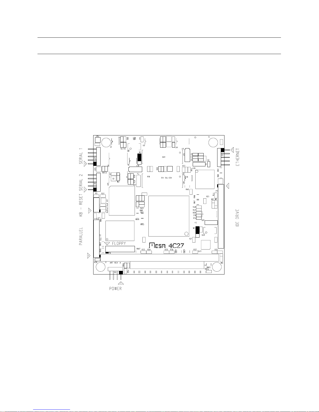
The 4C27 has two user settab le jumpers. One of the jumpers is used to enable or disable the
watchdog, and one is used for disconnecting the lithium cel l. When the words "up", and "down" are
used it is assumed that the 4C27 CPU card is oriented with its bus connectors J1 and J2 at the bottom
edge of the card (nearest the person doing the configuration).
DEFAULT JUMPER SETTINGS
Factory default 4C27 j umpering i s as f oll ows:
FUNCTION JUMPER SETTING
Lithium cell conne ct W1 UP - Clo ck ena ble d
WatchDog enable W5 UP - Watchdog enabled
Pa g e 8
Page 9
4C27 CPU USER'S MA NUA L
CONFIGURATION
DEFAULT JUMPER SETTINGS AND CONNECTOR LOCATIONS
Pa g e 9
Page 10

4C27 CPU USER'S MA NUA L
CONFIGURATION
WATCHDOG ENABLE
The 4C27 has a hardware watchdog t imer that will reset the CPU unless 'fed' periodically by
system software. In a DOS environment, the BIOS performs this service when it services the
hardware tic interrupt. When other operating systems are used, ( Linux,PSOS,QNX e t c. ) it may be
necessary to disable the watchdog. Watchdog enabl e is controlled by jum per W5. When W5 i s i n the
up position, the watchdog is enabled. When W5 is in the down posi tion, the watchdog is dis abled.
LITHIUM CELL ENABLE
The 4C27 has Lit hium coin cell that powers the clock/calendar and the CMOS setup st orage
RAM. If jumper W5 i s moved to the "down" positi on, the Lithium cel l will be disconnected. The 4C27
may be shi pped with the cel l disconnected, so you m ay n eed to move W5 to the "up" position in order
to use th e ba ttery ba cke d cl ock/ cal en dar.
The 4C27 BIOS d o es not use the CMOS setup RAM, so it is possible to run the 4C27 with no
Lithium cell if desired.
FLASH BIOS
The 4C27 BIOS chip is a 5V flas h memory device and can be reprogrammed in-place to update
the BIOS, or change from ROM-DOS to non ROM-DOS BIOS's. The program 4C27WBIO.EXE is
used to re-write the BIOS. The batch fi le ROMBIOS.BAT on the distribution di sk shows the standard
4C27WBIO parameters. Contact MESA if you need any special code in the BIOS. If you supply us
with a standard 55-AA type external ROM image, we can add it to the BIOS image for you.
Make sure that you do not have a memory manager installed when you update the BIOS, or
you may corrupt th e BIOS image. If this happens, you will need to get a new BIOS chip from
MESA.
Page 10
Page 11

4C27 CPU USER'S MA NUA L
CONNECTORS
POWER CONNECTOR
The 4C27 power connector (P8) is a 4 pin, single row, .1" header. The suggested mating
connector is an AMP MTA type connector 641190-4 (non-feedthrough) or 641198-4 (feedthrough).
These are both gold plated type connectors. Power pin arrangemen t is +5V, gnd, gnd, +5V. This pin out is compatible with newer (+5V only) 3.5 inch fl oppy drives.
Since the power connector on the 4C27 may power the whole PC/104 stack, it is suggested that
only gol d plated connectors be used. Tin pl ated connectors have a pronounced tendency to fai l over
time vi a i ncreased contact resistance when operated at any where near their rated current.
Power connector pinout is as f ollows :
PIN SIGNAL CURRENT RATING
1 +5V 1A
2 GND 1A
3 GND 1A
4 +5V 1A
The current ratings ab ove mean that the total +5V current needs to be l im ited to 2A.
KEYBOARD CONNECTOR
P5 is the AT keyb oard, reset-in and speaker connector. P5 is a 10 pi n dual row 2mm header. The
suggested mating connector is Suy in 20043-10G2 or 3M 152210-100-GG. This is an IDC (fl at cable)
type connector. A keyboard adapter cabl e is av ailabl e from MESA (The 4C27KBADPT).
An external reset switch i nput and speaker output are also availab le on P5. The reset circuit works
by grounding the /RESIN signal .
The speaker output is intended to drive hi gh i mpedance speakers (40 ohms or more) . Eight Ohm
speaker s will be to o q uiet for mo st ap plica tio ns . T he speaker common is +5V. An exter nal PNP
transistor c an be used to drive an eight ohm speaker to obnoxious volume l evels i f requi red.
Page 11
Page 12

KEYBOARD CONNECTOR
Keyboard connector pin-out is as follows:
PIN SIGNAL FUNCTION
1 SPKOUT Speaker out
2 SPKVCC Speaker common (+5V)
3 /RESIN Reset in
4 /RESINGND Reset common
5 MSCLK Mouse cl ock (unsupported)
6 KBCLK Keyboard clock
7 KBDAT Keyboard data
8 MSDAT Mouse data (unsupported)
4C27 CPU USER'S MA NUA L
CONNECTORS
9 KBGND Keyboar d g r ound
10 KBVCC Keyboard +5V
If a keyb oard is not used, it is possi ble to speed up 4C27 boot-up by groundi ng KBCLK. This i nf orms
the BIOS that no keyboard is present. This avoi ds the 2-3 second wai t for key b oard response to the
reset command.
SERIAL PORT CONNECTOR
P2 and P4 are the serial port connectors. P2 and P4 are 10 pin, dual row .1" headers. The
suggested mating connector is AMP PN 499934-1. This i s an IDC (flat cable ) type connector.
When t he flat cable from P2 or P4 is terminated with a male 9 pin D type connector (suggested
connector AMP 747306-4), the 9 pin conn ector wil l have a si m i l ar pi n-out to the AT type 9 pin serial
port. The pin 10 wire must be stripped from the cable before installing the D connector. A one foot
long serial port adapter cable is available from MESA .
The default BIOS port mapping selects P2 as COM1 and P4 as COM2.
Page 12
Page 13

4C27 CPU USER'S MA NUA L
SERIAL PORT CONNECTOR
Serial port connector pi n-out is as fol lows:
HEADER PIN DSUB PIN SIGNAL FUNCTION
1 1 DCD Handshake i n
2 6 DSR Handshake i n
32 RXD Data in
4 7 RTS Handshake out
53 TXD Data out
6 8 CTS Handshake i
7 4 DTR Handshake out
CONNECTORS
8 9 RI Handshake i n
9 5 GND Signal ground
10 NC +5V +5V user power o r k ey
PARALLEL PORT CONNECTOR
The 4C27 parallel port co nnecto r is P7. The connector for the parallel port uses a 26 pin, 2mm
header to save space. The 26 pin connector arrangement is such that when terminated with a standard
DB 25 con nector, the paral lel port pinout matche s th e IBM sta n d ard pinout. An adapter is avai lable
from MESA that converts between the 2 mm connector and standard 25 pin DB25F printer connector
(PRAD)
Page 13
Page 14

4C27 CPU USER'S MA NUA L
PARALLEL PORT
Parallel port connector pin-out is as follows:
HEADER PIN DSUB PIN SIGNAL FUNCTION
1 1 /PSTB Strobe (out)
2 14 /PAFD Auto LF ( out)
3 2 /PD0 Data 0
4 15 /PERROR Printer err or (in)
53 PD1 Data 1
6 16 /PINIT Reset pri nter (out)
74 PD2 Data 2
CONNECTORS
8 17 /PSLIN Select printer (out)
95 PD3 Data 3
10 18 GND Ground
11 6 PD4 Data 4
12 19 GND Ground
13 7 PD5 Data 5
14 20 GND Ground
15 8 PD6 Data 6
16 21 GND Ground
17 9 PD7 Data 7
18 22 GND Ground
19 10 /PACK Printe r Ack (in)
20 23 GND Ground
21 11 PBUSY D ata in (in)
22 24 GND Ground
23 12 PPE Paper out (in)
24 25 GND Ground
25 13 PSLCT Printer selected (i n)
26 NC +5V Key
Page 14
Page 15

4C27 CPU USER'S MA NUA L
CONNECTORS
FLOPPY CONNECTOR
The 4C27 floppy connector (P6) is a 20 pin 2m m connector in order to save space. An adapter is
available from MESA to connect to standard 34 pin .1" floppy drives (FLOPADPT).The connector
pinout is as follows:
HEADER PIN SIGNAL FUNCTION
1 VCC +5V power
2 /FRPM/LC Low write current select
3 /FINDEX Index
4 /FMTR0 Motor-on 0
5 /FDR1 Drive 1 select
6 /FDR0 Drive 0 select
7 /FMTR1 Motor-on 1
81 /FDIR Step direction
91 /FSTEP Step
10 VCC +5V power
11 /FWDATA Write data
12 GND Power ground
13 /FWGATE Write gate
14 /FTRK0 Track 0 detect
15 /FWRPROT Write protect
16 /GND Power ground
17 /FRDATA Read data
18 GND Power ground
19 /FHDSEL He ad select
20 /FDSKCHG Diskette change detect
IDE CONNECTOR
P3 is th e IDE connector. It is a 44 pi n, 2m m connector compatibl e wi th laptop type IDE drives. An
adapter is av ailab le f rom MESA to connect to standard 40 pi n .1" IDE drives (IDEADPT).
ETHERNET CONNECTOR
P1 is the ethernet connector It connect to the suppli ed TAU panel mount RJ45 with the suppli ed
10 pin header. Do not use longer cables than the 8" cable suppl ied with the TAU.
Page 15
Page 16

4C27 CPU USER'S MA NUA L
CPU OPERATION
POWER CONSUMPTION
The 4C27 is an all -CMOS CPU, so overall power consumpti on is typi cally less than 2 watts (about
350 mA). If the lowest power co nsumption is necessary, the CPU c lock can be stopped when not
active. This can reduce the CPU power to less than 100 mA. It is the responsibility of the application
program to stop the CPU when idle. An example program (STOPCLK.COM) is provided to
demonstrate stopping the CPU clock. If the absolute lowest power consumption is required, Mesa
can supply a version of the 4C27 that uses a lower po wer PAL. Please contact MESA for more
information on this low power CPU version.
STARTUP ERRORS
The BIOS performs a var ie ty of system te s t s at start u p . Ser io u s problems ar e r e p ort e d by bee p
codes. The red LED i s also f l ashed at the same time as the speaker beep. The BIOS beep codes are as
follows:
BEEPS ERROR
2 Bad external ROM checksum
3 External ROM initialization error
4 No system memory found
5 Can't boot - no resident language
6 BIOS R OM checks um error
7 Bad local R AM
8 VGA ROM initialization faulure
9 Invali d system configuration data (or forced default)
10 No ROM BIO S i mage f ound
11 Corrupted BIOS modul e found
WATCHDOG TIMER
The 4C27 is intended mainly for embedded system applications where there is no one to hit the
reset switch should something go awry. To prevent a crashed or otherwise hung system from
remai nin g so indefi ni tely , the 4C27 is provi ded with a bui lt i n watchdog ti mer that will reset the 4C27
if not 'fed' reg ularly. The t ime-o ut pe riod o f this co unter is a minimum of 500 milli-seconds. The
default INT 1C (user tic cl ock) task 'feeds' the watchdog.
User software must be careful not to disable
interrupts for more than these time periods or the watchdog may bite!
Page 16
Page 17

4C27 CPU USER'S MA NUA L
CPU OPERATION
SERIAL PORTS
The serial ports on the 4C27 are compatibl e with 16C550A type UARTS . These UARTS have 16
byte receive and transmit FIFO's. The serial ports can be setup by the BIOS to be COM1 and COM2
or COM3 andCOM4 (vide inf ra). Def ault setup is COM1 and C OM2 (0x3F8 and 0x2F8), but can be
changed with the SET4CSIO util ity.
PARALLEL PORT
The 4C27 parallel port is capable of bidirectional operation. The parall el port I/O address can be
set to be at the LPT1, LPT2, o r LPT3 locations. Default port location is 0x278 but can be changed
with th e SET4CSIO utility.
FLOPPY INTERFACE
P6 is a floppy interface. The 4C27 will wo r k w it h 1. 4 4M flo ppy drives. P 6 is a 20 pin 2MM
connector to save space. An adapter is av ailabl e to connect to standard 34 conductor cable.
IDE INTERFACE
The IDE interf ace on the 4C27 uses a 44 pi n 2mm connector. This i s compatibl e wi th l aptop type
hard drives (2.5" and smal ler). The 44 pin connector al so supplies power to these drives. An adapter is
avai labl e for the stand ard 40 pin .1 " connector. (IDEADPT)
HARD DRIVES
The 4C27 B IOS supports IDE type hard drives. The 4C27 BIOS reads the hard drive parameters
directly from the IDE drive. This means that no drive parameter information is stored on the 4C27
card. T his makes it much easier to install and change hard drives. I t is es pecially co nvenient when
using ATA (PCMCIA format) removeable drives.
Hard drives are added to the 4C27 drive l i st after local f lash drives. For example if you have a two
drive flash disk system, the fl ash drives would be assigned letters C: and D: and the hard drive would
become E:
If ROM-DOS is used, The ROM drive (with COMMAND.COM etc.) is al ways assi gn ed the last
drive number. The ROM drive in the example above woul d be drive F:
Page 17
Page 18

4C27 CPU USER'S MA NUA L
CPU OPERATION
ETHERNET INTERFACE
The 4C27 has an optional on card 10Ba seT Et hernet interface. This interface uses the Crystal
semi conductor CS8900 ch i p. OD I, packet driver and NDIS dri ve rs are suppl i ed wi th the 4C27 wh en
the Ethernet opti on is incl uded. The Ethernet connector is a 10 pi n h eader intended to connect to the
suppli ed panel m ount RJ45 adapter (TAU).
longer than 8"
The default Ethernet chip I/O address is 0300-030FH. This can b e changed i f necessary wi th the
setup utility on the CS8900 driver disk. The Ethernet interface uses IRQ 10 as the default interrupt.
This can also b e changed wi th the CS8900 setup utility.
The Ethernet address is printed on a label on the back of the 4C27 card.
REMOTE BOOT IN G
A BIOS wi th a RPL (Novel ls rem ote boot protocol) Ethernet boot ROM image i s i ncl uded on the
distri bution di sk, as i s a BIOS with a generic B OOTP/TFTP boot program.
To use the generic remote boot BIOS you need a server that supports BOOTP and TFTP. You
also need unix compatible system to gener ate the bo ot image. T he gener ic boo t BI OS curr ently
supports booting DOS , Li nux, an d NetBSD. For more i nform ation on the gene ric boot BIOS contact
MESA.
You install these by re-writing the 4C27BIOS with the 4C27WBIO utility. You may want to
check with MES A if your distrib ution disk i s not recent as there may hav e been 4C27 B IOS updates.
Do not install the RPL boot ROM image unless you are sure you can support it, as you cannot
abort the net load and boot from floppy. This will leave you with a broken 4C27 until you get a new
BIOS chip
.
The cable between the 4C27 and the TAU should be no
Page 18
Page 19

4C27 CPU USER'S MA NUA L
CPU OPERATION
SETUP STORAGE
Many 4C27 options can be s aved in the serial EEPROM on the 4C27 card. These options i nclude:
initial baud rate, COM port locations, parallel port location, etc. These parameters can be set with the
provided utility SET4C27.EXE
SET4C27 reads a text fi le of setup options, and programs these into the 4C27's EEPROM. These
setup fil es have a default extension of .CF. SET4C27 and a number of configuration fi les are located in
the UTILS directory of the 4C27 di stribution f l oppy. SET4C27 is inv oked with the conf i guration fi l e
name as a parameter:
SET4C27 4C27.CF
Would conf igure the 4C27 wi th the EEPROM settings in the 4C27.CF confi guration fi le.
SET4C27 has three command l i ne swi tches : /D, /N and /Q. These comm and li ne s witches fol l ow
the fil e n ame. The /D option causes the 4C27 EEPROM to be initi al i zed to it's default configuration.
When the /D option is used, no file name is needed. The /N opt ion causes the configuration file to
modify the defa u lt c onfig ur at ion, and st o r e t he r esult into the EEPROM. I f /N is not specified, all
options not specifi call y changed in the confi guration fi le wil l remain at their previous settings.
As l ong as the /N or /D switches are not used, configuration fi les l oaded with SET4C27 onl y affect
the options specif ied in the file. This makes it possible to separate the confi guration files i n to pieces
that only affect a c ertain aspect o f 4C27 operat ion. Note t hat E E PROM settings do not t ake effect
until the 4C27 is reset. For more informati on on setup options you should li st the 4C27.CF fi l e i n the
UTILS directory of the distribution disk. This file has all o f the available setup opt ions specified.
Normal usage of the 4C27.CF file is to leave all of the options in the file, but comment out the
undesired options. options c an be commen ted out by preceding the li ne with a semicolon.
NOTE: The following configu ration parameters may require chan ges before the 4C27 will
work in your application
The IDE_D RIV E_CHE CK par ameter de te rmines whether or no t t he 4C27's BI OS check s for
IDE drives. The default setting of this parameter is OFF, which means that as shi pped, a 4C27 wil l n ot
detect IDE drives. Thi s is done to speed boot-up when no IDE drives are present.
Another important parameter is SERIAL_CONSOLE_ENABLE. This determines if the 4C27
will use COM1 as a console if n o video card is present. The default SERIAL_CONSOLE_ENABLE
setting i s YES. If you have a peripheral device connected to COM1 that would be confused by startup
messages, and are not using the serial console, you should set this parameter to NO.
The ENABLE_RAMDISK parameter should be set to NO if you are not using the flash drive.
T h is will save a f e w KBytes o f RAM, a void printing error me ssa g e s, and may help avoid problems
when booting some non-DOS operating systems.
Since it is possible t o program the EEPROM setup in such a way as to make the 4C27 inaccessibl e, there is a w ay to abort loading the EEPROM values and lo ad the BIOS default values for
system parameters instead.
the system is reset.
.
You do this by holding the right shift key down on the keyboard when
Page 19
Page 20

4C27 CPU USER'S MA NUA L
CPU OPERATION
SETCTSIO
The serial and paral lel port settings c an also be changed dyn amical ly with the i ncluded setup utility
SET C TSIO .E XE . T hese s et ting are vo latile, and will revert t o the defa ult set t ings at po wer u p o r
hardware reset. The setup utility can be run as part of your AUTOEXEC.BAT file.
SETCTSIO i s i nvoked wi th one comm and l i ne param eter, a confi guration fi l e nam e:
SETCTSIO COM3COM4.CFG
T he c o m ma n d lin e p a r a m e t e r is th e n a m e o f th e c o n fig u r a tion fil e . The c o n fig u r a tion file is a n
ASCII file containing the configuration parameters. The UTILS director y of the 4C27 distribution
disk has two example configuration files, COM3COM4. CFG and STAN DARD.CFG . Y o u should
use these fi les as a starting point to creating your own configuration fil es.
The format of the configuration file is very sim ple: each li ne of the confi guration file consists of a
parameter name followed by a parameter value. If a parameter name is not specified in the
configuration fil e, that parameter will be set to the default value shown i n the foll owin g tabl e.
The parameter names, parameter values, and default parameter values are as foll ows:
PARAMETER PARAMETER VALUES DEFAULT
PP-ADDRESS OFF 278
278
378
3BC
The PP-ADDRESS parameter selects the location of the parallel port. The parallel port can be
dis abled i f desired by setting the parameter to ' OFF'
PARAMETER PARAMETER VALUES DEFAULT
PP-MODE UNI-DIRECT UNI-DIRECT
BI-DIRECT
The PP-MODE parameter sets the operational mode of the parallel port. The default unidirectional mode is the standard printer port mode. When set to the bi-directional mode, bit 5 of the
printer contro l port determines the signal direction on the printer dat a lines. A low on bit 5 sets the
l in es to the outp ut dir ecti on, a h igh on bi t 5 sets the data l in es to the in put dir ecti on.
Page 20
Page 21

4C27 CPU USER'S MA NUA L
CPU OPERATION
SETCTSIO
PARAMETER PARAMETER VALUES DEFAULT
PRIMSER-ENABLE YES YES
NO
This parameter enables or disables the primary serial port.
PARAMETER PARAMETER VALUES DEFAULT
SECSER-ENABLE YES YES
NO
This parameter enables or disables the secondary serial port.
PARAMETER PARAMETER VALUES DEFAULT
COM3&4-ADDRESS 338-238 338-238
3E8-2E8
2E8-2E0
220-228
The COM3&4-ADDRESS parameter all ows selecti on of the l ocations of serial ports COM3 and
COM4. These port addresses will not be used unless the prim ary or secondary serial port has COM3
or COM4 selected as an address.
Note that 3E8 and 2E8 are the most commonly used locations for COM3 and COM4
PARAMETER PARAMETER VALUES DEFAULT
PRIMSER-ADDRESS 3F8 3F8
2F8
COM3
COM4
Sets the address of the pri mary seri al port (The port connected to P2). If set to COM3 or COM4,
the address is determined by the COM3&4-ADDRESS parameter.
Page 21
Page 22

4C27 CPU USER'S MA NUA L
CPU OPERATION
SETCTSIO
PARAMETER PARAMETER VALUES DEFAULT
SECSER-ADDRESS 2F8 2F8
3F8
COM3
COM4
Sets the address of the secondary serial port (The port connected to P3). If set to COM3 or
COM4, the address i s determi ned by the COM3&4-ADDRESS parameter.
Page 22
Page 23

4C27 CPU USER'S MA NUA L
CPU OPERATION
SERIAL FILE DOWNLOAD
To allow transferring of application programs to the 4C27, which m ay not have a fl oppy drive or
other means of transferring programs, a set of utility programs are provided. They are call ed SEND
and RECV.
SEND and RECV co mprise a very simple file download ut ility set. When the 4C27 is supplied
with ROM-DOS, RECV is normal ly suppli ed buil t into the BIOS ROM as part of the ROM drive (C:).
The fi rst requirem ent for SEND and RECV to work is the proper cable. Thi s cabl e has only three
wires, and is a 'data only null modem' cable. Assuming that your host machines serial port is a 9 pin
male (AT pinout) type, and that the 4C27 has i t's serial port adaptor cable, the cabl e would have 9 pin
female connectors at both ends and the following connections:
9 pin 9 pin
5 -------- 5 ( ground )
2 -------- 3 ( data <- )
3 -------- 2 ( data -> )
If your host machi n e has a 25 pin serial connector, the cable needs a female 25 pi n connector on
the host end and a female 9 pin connector on the client end. This cable must have the following
conne ctions:
25 pin 9 pin
7 -------- 5 ( ground )
2 -------- 2 ( data -> )
3 -------- 3 ( data <- )
If you do not wish to make a cable, a down load adaptor cable is available from MESA. The part
name i s DW LDADPT. This i s a five foot cabl e with a 10 pi n header on one end (the 4C27 end) and a
female 9 pin D connector at the other end. The 9 pin D connector connects to the host system's serial
port.
Page 23
Page 24

4C27 CPU USER'S MA NUA L
CPU OPERATION
SERIAL FILE DOWNLOAD
SEND runs on a host machine. This h ost machi n e must be a PC wi th a standard COMX RS-232
serial port available.
SEND is invoked this way:
SEND PPP [BR]
PPP is the hexadecimal port address of the serial port on the host machine (3F8 = COM1, 2F8 =
COM2, 3E8 = COM3, and 2E8 = COM4). BR is an optional baud rate paramete r. If BR is not
supplied, se nd uses 9600 baud. For example SEND 2F8 38400 would send files through COM2 at
38400 baud.
Once SEND is running on the host machine, RECV is run on the client CPU card t o download
files.
RECV is invoked this way:
RECV RFN LFN [BR] [Q]
RFN is the remote file name (the source file) which is relative to the path where send was
launched. LFN is the local file name (t he target file). The Q paramet er causes SE N D t o be a bo r t e d
when the file transfer is complete. BR is an optional baud rate parameter. If BR is not suppl ied, RECV
uses 9600 baud. For example RECV FOO GOO 38400 Q would get the remote file F OO, write it to
the local fil e GOO, and abort SEND when done. All data transf ers would be done at 38400 baud.
The remote file name can include a drive and path, allowing access to differe nt d irec tories,
network drives etc.
If y ou set the baud rates on the command l ine, the SEND baud rate must match the RECV baud
rate. Maximum practical baud rate is 115200 baud. You may not be able to use the maximum baud
rate, depending on your host CPU speed, serial port characteristics, interconnect cable etc. (Your
mi le age may vary ).
CONSOLE SWITCHING
To simplfy system initiali zation, the 4C27 will use the COM1 serial port as the console if no video
adap t o r is fou nd at syst em st ar t up . T he defa u lt baud rat e is 9600. This console re-direction can be
dis abl ed in the EEPROM setup if desi red.
Page 24
Page 25

4C27 CPU USER'S MA NUA L
ROM-DOS
ROM-DOS
Datalight ROM-DOS is an availble option for the 4C27. ROM-DOS is a DOS 6.22 compat ible
operating system that resides in the BIOS chi p and does not use any f lash di sk space.
ROM DRIVE
When ROM-DOS is used, its COMMAND.COM, AUTOEXEC.BAT and CONFIG.SYS reside
in a ROM drive that is part of the BIOS image. This drive is always the last physical hard drive in the
system. In other words,, if you have a 4C27 wi th a fl ash drive (Drive C :) and an IDE drive (Drive D:),
this ROM drive would be drive E :. Because the AUTOEXEC.BAT and CONFIG.SYS files are buil t
into the BIOS image , it is difficult to c hange them.. To allow changes in the start up sequence ,
alternate files are used to supplement the AUTOEXEC.BAT and CONFIG.SYS files on the ROM
drive. These fi les are LAUNCH.BAT and MORECFG.SYS.
The AUTOEXEC.BAT file in the ROM drive calls C:LAUNCH.BAT. This is where you would
put your normal program launch sequence. Note t hat t he default drive is still the ROM dr ive when
LAUNCH.BAT is called, so the first thing done in LAUNCH.BAT should probably be to set the
default drive to C :
The C:MORECFG.SYS file is where normal CONFIG.SYS options should go. As with
LAUNCH.BAT , the default drive is still the RO M drive, so any drivers should be prefaced with an
absolute path.
BOOTING
Sin c e R O M -D O S " b o ot s" fr om me m or y, a 4 C 2 7 w ith a ROMDO S B IOS will not b oo t fro m a
floppy. If it is necessary to boot from a floppy , You can hold down the ALT key and the ROM-DOS
loader will print menu of boot options. This can help to fix a 4C27 that launches a b roken appli cation
progr am f rom th e fl ash dis k.
REMDISK AND REMSERVE
If you are usi n g ROM-DOS, the REMDISK and REMSERVE utiliti es can be used fo r serial file
upload and download and are generall y sim pler to use than the SEND-RECV utilities. Please refer to
the ROM-DO S manu al for more i nform ation on REMDISK and REMSERVE.
Page 25
Page 26

4C27 CPU USER'S MA NUA L
DISK EMULATOR OPERATION
GENERAL
The 4C27 has an optional built in nonvolatile disk emulator w ith a capacity of up to 16M bytes
usin g NAND fl ash devices .
The 4C27 disk emulator is viewed as a hard disk by syste m s o ft ware. This means that the first
emulated drive will be drive C: , and the next emulated drive will be drive D:.
RELIABILITY
In an em bedded system environment where a system that won't boot is basically a fail ed system, it
is import ant to unde rst and so me charac ter istics of the DOS o pera ting syste m that applies to disk
access. When DOS writes a file, it writes t o the FAT and directory areas of the drive (emulated or
real).
If there is any chance that a system can be reset or power can fail when writing to this disk, all
information on the disk could become inaccessible,
The reason is that when DOS writes to a directory or FAT area it al w ays wri tes a full sector, not
just the directory or FAT entry required. If the secto r write is not completed, the sector with the
directory or FAT entry that was being written will have an invalid CRC. This can affect any fi le on the
drive!
In appl ic ations th at do frequent di sk wri tes, there are two possib l e soluti ons to this probl em. The
first solution is to disable emulated disk CRC checking. This will mak e a part ia lly r e w rit te n secto r
readable by the operating system. This will o n ly im p rove the odds of surviving a power off or reset
during a file wr it e, not to tally eliminate the problem. Turning off CRC's will also mask pos sible
hardware pro blems, so is not ge nerally suggested. The second solution is to configure a two drive
system, with a drive (usuall y C :) used as the software drive, and the other drive (usually D:) used as
the data drive. Any files writes during normal operation would be done to the D: drive. If any problem
occurs on the D: drive, software on the C: drive can attempt to recover the data, and then re-in itial ize
the D: drive.
not
just the file that was being written.
Page 26
Page 27

4C27 CPU USER'S MA NUA L
DISK EMULATOR OPERATION
DISK EMULATOR INITIALIZATION
The disk emulator is initialized at t he fac t ory but you may want to re-initialize it to c hange t he
number of drives (2 chip dis k emulators are initali zed as a si ngle driv e at the f actory).
This initialization is done with INI TRMDB.EXE. INITRMDB.EXE is supplied in the DISK
subdirectory of the 4C27 distribution disk. If INITRMDB is run with a /L parameter, it will lis t the
type and capacity of disk emulator chips installed on the 4C27.
To initialize a disk emulator, you invoke INITRMDB as follows:
INITRMDB /CStartChip /NNumberOfChips /T
Where StartChi p is 0 or 1, NumberOfChi ps is 1 or 2
On the 4C27, there are 1 or 2 chips. If you want to initialize a 2 chip disk emulator , the
INITRMDB comm and woul d be:
INITRMDB /C0 /N2 /T
( Initial ize di sk starti ng at chip 0, usi ng 2 chips - DOS format)
It is also possible to initialize tw o independent disk emulators o n 4C27's with 2 disk emulator
chips by invoking INITRAMD twice, once per chip:
INITRMDB /C0 /N1 /T
( Initial ize di sk starti ng at chip 0, usi ng 1 chips - ROM-DOS format)
INITRMDB /C1 /N1 /T
( Initial ize di sk starti ng at chip 1, usi ng 1 chips - ROM-DOS format)
Once the disk em ulator has been i niti ali zed, the 4C27 needs to be reset before the new disk will be
recognized by the operating system.
After INITRMDB is run, you must run FDISK and FORMAT (From ROMDOS or DOS
dependi ng on whether you have ROMDOS i nstall led)
Page 27
Page 28

4C27 CPU USER'S MA NUA L
INSTALLATION
GENERAL
When the 4C27 h as been properly conf igured for its appl ication, it can be inserted into a PC/104
st ack . Th e st and offs shou ld t hen be tigh te ned t o secure the 4C27 in its place. When the 4C27 is
secured in the stack the I/O connectors headers can be plugged in from the sides.
I/O CONNECTOR OR IENTATION
The serial port connectors on the 4C27 are 10 pi n, righ t angle .1 " headers. Pin 10 of the seri al port
connector can be cut, and a keying plug installed in the cable mou nt header if desired to pr event
reverse installation of the serial cabl es. If more positive polarization is desi red on the 10 pi n headers,
center pol arized IDC header connectors should be used. These connectors will not fully mate with the
pins on the 4C27 i f i n stall ed backwards. A suggested center polarized 10 pi n IDC header is AMP PN
499934-1.
All connectors on the 4C27 have their pi n one ends marked with a white square on the circuit card.
This corresponds with the red stripe on typi cal f lat cable assem blies.
Page 28
Page 29

SPECIFICA TIONS
POWER S U PPLY
Voltage 4.5 5.5 V
Supply cur rent (full speed) --- 550 mA
Supply cur rent (sleep mode) --- 125 mA
BUS LO AD ING A ND DR IVE:
Input capaci tance --- 20 pF
Input leakage current --- 5 uA
4C27 CPU USER'S MA NUA L
REFERENCE INFORMATION
MIN MAX UNIT
Output drive capability --- 150 pF
Output sink current 6 --- mA
ENVIRONMENTAL:
Operating temperat ur e range
o
-I versi on -40 +85
-C version 0 +70
C
o
C
Relative humid ity 0 90 Percent
Non-condensing
Page 29
Page 30

4C27 CPU USER'S MA NUA L
REFERENCE INFORMATION
WARRANTY
Mesa Electronics warrants the products it manufactures to be free effects in material and
workmanship under normal use and service for the period o f 2 years from date o f purchase. This
warranty shall not apply to products which have been subject to misuse, neglect, accident, or
abnormal conditions of operation.
In the event of fa ilure of a product covered by this warranty, Mesa Electro nics, will rep air a ny
product returned to Mesa Electr o nics within 2 years of original purchase, provided the warrant o r 's
examination discloses t o its satisfaction that the pro duct was defective. The warrantor may at its
option, repl ace the product in l ieu of repai r.
Wi th regard to any product returned wi thin 2 y ears of purchase, sai d repairs or repla cement will be
made without charge. If the failure has been caused by misuse, neglect, accident, or abnormal
conditions of operation, repairs will be billed at a nomi nal cost.
THE FOREGOING WARRANTY IS IN LIEU OF ALL OTHER WARRANTIES,
EXPRESS OR IMPLIED. INCLUDING BUT NOT LIMITED TO ANY IMPLIED
WARRANTY OF MERCHANTABILITY, FITNESS, OR ADEQUACY FOR ANY
PARTICULAR PURPOSE OR USE. MESA ELECTRONICS SHALL NOT BE LIABLE FOR
ANY SPECIAL, INCIDENTAL, OR CONSEQUENTIAL DAMAGES, WHETHER IN
CONTRACT, TORT, OR OTHERWISE.
If any failure occurs, the following steps should be taken:
1. No tify Mesa Electr onics, giving full details of the d ifficulty. On receipt of this information,
service data, or shipping instructions will be forwarded to you.
2. On receipt of the shipping instructions, forward the product, in its original protective
packaging, transportation prepaid to Mesa Electronics. Repairs will be made at Mesa Electronics and
the product returned transportati on prepaid.
Page 30
Page 31

4C27 CPU USER'S MA NUA L
REFERENCE INFORMATION
SCHEMATIC DIAGRAMS
Page 31
Page 32

4C27 CPU USER'S MA NUA L
Page 32
 Loading...