

Page 1

Owner’s Manual
Page 2

Greetings from the Home of Tone®
…You, smart player and intuitive human, have put your trust in us to be your amplier
company. is is something that we do not take lightly. By choosing this instrument to be
part of your musical voice, you have become part of the MESA® family… WELCOME...
and to those of you who are already part of the Mesa family, we thank you for returning
to your roots.
Our goal is to never let you down. Your reward is that you are the new owner of an amp,
bred of ne heritage, benetting from the many pioneering and patented MESA circuits
as well as fresh cutting edge research and development eorts, leading to this new and
exciting model. We feel confident that this amp will inspire many hours of musical
satisfaction and lasting enjoyment. It was built with you in mind, by players who know
the value of a ne musical instrument and the commitment it takes to make great music.
e same commitment to quality, value and support we make to you… our new friend.
Page 3

Table of Contents
PRECAUTIONS
OVERVIEW ____________________________________________________________________________________ 1-2
INSTANT GRATIFICATION _________________________________________________________________________ 3
FRONT PANEL
INPUT JACK ____________________________________________________________________________________ 3
MUTE SWITCH __________________________________________________________________________________ 3
ACTIVE/PASSIVE SWITCH ________________________________________________________________________ 3
INPUT CONTROL & O/D LED ______________________________________________________________________ 3
HIGHPASS FILTER ______________________________________________________________________________ 3-4
BASS CONTROL ________________________________________________________________________________ 4
TREBLE CONTROL ______________________________________________________________________________ 4
PARAMETRIC MID EQ CONTROLSL ________________________________________________________________ 4
PASSIVE MID CONTROL __________________________________________________________________________ 4
MASTER VOLUME CONTROL ____________________________________________________________________ 4-5
POWER AMP DAMPING CONTROL _________________________________________________________________ 5
POWER LED ____________________________________________________________________________________ 5
2 OHM LED _____________________________________________________________________________________ 5
PROTECT LED _________________________________________________________________________________ 5-6
LIMIT LED ______________________________________________________________________________________ 6
REAR PANEL
POWER SWITCH ________________________________________________________________________________ 6
IEC POWER INLET _______________________________________________________________________________ 6
OPERATING POWER REQUIREMENTS ______________________________________________________________ 6
COOLING FAN __________________________________________________________________________________ 6
SPEAKER OUTPUTS ____________________________________________________________________________ 6-7
SPEAKER IMPEDANCE ___________________________________________________________________________ 7
SPEAKER POLARITY (OR PHASE) _________________________________________________________________ 7
IMPEDANCE SELECTOR SWITCH __________________________________________________________________ 7
HEADPHONE OUTPUT ___________________________________________________________________________ 8
MUTE / PEQ BYPASS FOOTSWITCH ________________________________________________________________ 8
EFFECTS LOOP _________________________________________________________________________________ 8
AUX INPUT _____________________________________________________________________________________ 8
DIRECT OUT SECTION __________________________________________________________________________ 8-9
USB DEVICE POWER ____________________________________________________________________________ 9
DISCUSSION ABOUT SMPS AND CLASS D _______________________________________________________ 10-11
TROUBLESHOOTING _________________________________________________________________________ 11-13
FACTORY SAMPLE SETTINGS ____________________________________________________________________ 14
USER SETTINGS _______________________________________________________________________________ 15
SPECIFICATIONS _______________________________________________________________________________ 16
SERVICE INFORMATION _________________________________________________________________________ 17
BLOCK DIAGRAM ______________________________________________________________________________ 18
PARTS LIST ___________________________________________________________________________________ 19
Page 4

IMPORTANT SAFETY INSTRUCTIONS
Read these instructions.
Keep these instructions.
Heed all warnings.
Follow all instructions.
Do not use this apparatus near water.
Clean only with dry cloth.
Do not block any ventilation openings. Install in accordance with the manufacturer’s instructions.
Do not install near any heat sources such as radiators, heat registers, stoves, or other apparatus (including amplifiers) that produce heat.
Do not defeat the safety purpose of the polarized or grounding-type plug. A polarized plug has two blades with one wider than the other. A grounding type
plug has two blades and a third grounding prong. The wide blade or the third prong are provided for your safety. If the provided plug does not fit into your
outlet, consult an electrician for replacement of the obsolete outlet.
Protect the power cord from being walked on or pinched particularly at plugs, convenience receptacles, and the point where they exit from the apparatus.
Only use attachments/accessories specified by the manufacturer.
Unplug this apparatus during lightning storms or when unused for long periods of time.
Refer all servicing to qualified service personnel. Servicing is required when the apparatus has been damaged in any way, such as power-supply cord or plug
is damaged, liquid has been spilled or objects have fallen into the apparatus, the apparatus has been exposed to rain or moisture, does not operate normally,
or has been dropped.
To insure proper ventilation always make sure there is at minimum four inches (101.6mm) of space behind the rear of the apparatus. The ventilation should
not be impeded by covering the ventilation openings with items, such as newspapers, tablecloths, curtains, etc. Do not impede ventilation by placing objects
on top of the apparatus which extend past the rear edge of its cabinet.
When Rack Mounting this unit proper ventilation space must be maintained. Do Not cover or block Front and Rear and allow at least 2” of open “breathing”
space on both sides of the unit.
No naked flame sources, such as lighted candles, should be placed on the apparatus.
The apparatus shall not be exposed to dripping or splashing and no objects filled with liquids, such as vases, shall be placed on the apparatus.
WARNING: To reduce the risk of fire or electric shock, do not expose this apparatus to rain or moisture.
The AC plug is the mains disconnect. The plug should remain accessible after installation.
WARNING: EU: permission from the Supply Authority is needed before connection.
WARNING: Always make sure proper load is connected before operating the amplifier. Failure to do so could pose a shock hazard and may result in damage
to the amplifier.
Do not expose amplifier to direct sunlight or extremely high temperatures.
Always insure the amplifier is properly grounded. Always unplug AC power cord before performing ANY service to the amplifier, including but not limited to
changing the fuse. Use only same type and rating when replacing fuse.
Keep amplifier away from children.
To avoid damaging your speakers and other playback equipment, turn off the power of all related equipment before making the connections.
Do not use excessive force when handling buttons, switches and controls. Do not use solvents such as benzene or paint thinner to clean the unit.
Always connect to an AC power supply that meets the power supply specifications listed on the rear of the unit. Export models: always insure unit is wired for
proper voltage. Make certain grounding conforms with local standards.
YOUR AMPLIFIER IS LOUD! EXPOSURE TO HIGH SOUND VOLUMES MAY CAUSE PERMANENT HEARING DAMAGE!
Your MESA/Boogie® Amplier is a professional instrument. Please treat it with respect and operate it properly.
READ AND FOLLOW INSTRUCTIONS OF PROPER USAGE.
Page 5

Operating Instructions
BASS
500HZ 1.3KHZ
PARAMETRIC EQUALIZER
2-STAGE CLASS A TUBE PREAMPLIFIER
2.6KHZ
TREBLE MASTERINPUT
HIGHPASS
FILTER
POWER AMP
DAMPING
PASSIVE
MID
INPUT
25HZ 125HZ
80HZ 1KHZ
0 dB
-12 +12 LOW
MED
HIGH
0 dB
-12 +12
0 dB
-12 +12
150HZ 2.5KHZ 300HZ 5KHZ
PEQ
BYPASS
POWER
PROTECT
2 OHMS
LIMIT
O/D
PASSIVEPLAY
ACTIVEMUTE
SUBWAY® WD-800
™
OVERVIEW:
Congratulations on your choice of the SUBWAY WD-800™ and welcome to the MESA/Boogie® family! First, we would like to thank
you for choosing us as your amplifier company and trusting us to help create your musical voice. This is something we never take for
granted and you’ll find that we are here and ready to assist you should you ever need help. Our goal is to help you sound your best
at all times! We feel confident that your new amplifier will bring you many years of reliable service, rewarding inspiration and create
for you a newfound freedom to express your music.
You have chosen an amplifier bred of a fine heritage, and this model is our testament to our legacy of tone. Its forefathers can be
traced back to the very first MESA amplifier ever built, the MESA 450 Bass Head. In fact, the first 5 MESA amplifiers built in the Lagunitas mountain shack were Bass amps… a piece of trivia little known and overshadowed by our overwhelming notoriety for guitar
amplification. But we’ve always loved the Bass, and have—since day one—been committed to elevating its stature through our art
form. The bloodline for MESA bass continued with the first rack-mount chassis bass amplifier in 1980, the D-180. The mid-eighties
saw the introduction of the BASS 400 and later in 1988, the BASS 400+ with its stunning pitch, punch and power delivered by an
additional 6 x 6L6s to bring the total to twelve 6L6 power tubes in the mighty power section.
The 400+ went on to become a classic used by the world’s most talented bassists for two decades. Paul McCartney, Mark King, Stanley Clark, Jack Blades, Michael Anthony, Blasko and Bootsy Collins, are but a few of the international stars that put the 400+ center
stage to anchor the band during its 20 year build cycle. Those iconic amps still bring top dollar when you can find one changing hands
on the pre-owned market. While MESA has since pioneered an entire line of tube-driven mosfet amplifiers (including the legendary
Walkabout) that shored up our position in the bass market, changing times have encouraged us to take what we have learned over
this time and create a whole new approach to the bass amp, while remaining true to our heritage and tradition of tone.
Tone Freaks Rejoice! The SUBWAY WD-800 is the next step in the MESA Bass Amp Bloodline. A tone dripping powerhouse that’s both
compact and lightweight, packaged to go the distance with features, packaging and control over the entire bass spectrum makes it
an iconic step forward in bass amplification. The SUBWAY WD-800 is made in Petaluma, California with the World’s Finest Materials.
FRONT VIEW: SUBWAY® WD-800™
POWER
O/D
ACTIVEMUTE
PASSIVEPLAY
INPUT
REAR VIEW: SUBWAY® WD-800™
OFF ON
MAX AVG PWR CONSUMPTION 400W
MAINS FUSE: INTERNAL T-6.3A/250V
2-STAGE CLASS A TUBE PREAMPLIFIER
POWER
AMPLIFIER
44YV
HIGHPASS
FILTER
25HZ 125HZ
500HZ 1.3KHZ
80HZ 1KHZ
BASS
Risk of Electric Shock. Do Not Open.
CAUTION:
No user serviceable parts inside.
MADE IN PETALUMA, CA, USA WITH THE WORLD’S FINEST MATERIALS
SPEAKER OUTPUTS
2 OHM MINIMUM LOAD
150HZ 2.5KHZ 300HZ 5KHZ
0 dB
-12 +12 LOW
0 dB
-12 +12
PARAMETRIC EQUALIZER
IMPEDANCE
2 Ω 4/8 Ω
HEAD
PHONES
2.6KHZ
0 dB
-12 +12
Replace fuse with same type/rating only.
Do not expose to rain or moisture.
USB DEVICE PWR
POWER ON
MUTE/PEQ BYP
(FOOTSWITCH)
PEQ
BYPASS
PASSIVE
MID
WARNING:
USB
FX LOOP
RETURN SEND
TREBLE MASTERINPUT
SUBWAY® WD-800
AUX
TUNER
INPUT
OUTPUT
2 OHMS
PROTECT
LIMIT
POWER AMP
DAMPING
HIGH
MED
™
TUBE TYPE: 12AT7
CATHODE BIASED CLASS A
DIRECT OUTPUT
(PHANTOM POWER PROTECTED)
LEVEL
SOURCE
POST-EQ
PIN 1
LINE
LIFT
INPUT
POWER
100V-240VAC
~50/60Hz
RATED
POWER
400 WATTS/8 OHM
800 WATTS/4 OR 2 OHM
PAGE 1
®
SUBWAY
WD-800™ BASS AMPLIFIER
PRE-EQ MIC GROUND
Page 6

OVERVIEW: FRONT PANEL
The SUBWAY WD-800 begins with the front panel input section, which is comprised of the INPUT jack, MUTE switch and ACTIVE/
PASSIVE switch. The INPUT jack feeds a high impedance J-FET input amplifier which provides appropriate loading for all active and
passive pickups (including most piezo types). The MUTE switch silences the signal from the INPUT jack to the SPEAKER output,
HEADPHONE output and DI output for silent tuning with a tuner connected in line with the instrument or to the TUNER OUTPUT jack.
The ACTIVE/PASSIVE switch sets the gain of the input stage, reducing gain in the active position to prevent unwanted distortion from
very high output basses and pedals. Indicator (tally) LEDs are provided for all switched functions.
The preamp section includes a hybrid J-FET/12AT7 (or 12AU7) vacuum tube variable GAIN stage incorporating tuned anti-saturation
technology to prevent even momentary sticking to the supply rails, and allow instantaneous recovery for an even more graceful tube-like
feel when driven hard into overdrive. A precision variable HIGH PASS FILTER is included to block unwanted sub-sonic signal (as well
as for specific tone shaping functions), and an O/L (overload) LED is provided to give visual indication of when the preamp is being
overdriven. “Sticking to the supply rails” occurs when the signal is driven so hard into clipping that excess charge accumulates. The
time required to clear this charge causes the signal to “stick” to the supply rails during these extremes, creating a visual and audible
kink in the shape of the waveform. The anti-saturation network we’ve included in your WD-800 prevents you from experiencing this
unpleasant artifact.
Tone shaping on the SUBWAY WD-800 includes an active Baxandall EQ which consists of LOW and HIGH FREQUENCY shelving
bands, plus an exclusive passive mid control (with make-up gain), a unique hybrid approach to the mid tone stack voicing within the
tube preamp. There is an additional 3 band ACTIVE PARAMETRIC MID EQ section which allows for pin-point tone sculpting with
foot-switch bypass and LED indicator.
Next, there is a MASTER volume control which sets the amplifier’s output level. The combination of positions between the input GAIN
and MASTER volume, along with the signal strength from your bass (which is also affected by your playing style and touch) allows
for a wide range of tones and feel, from shimmering clean to overdriven and everything in between.
Finally, there is a POWER AMP DAMPING control. What is this you might ask? By adjusting this control, you can loosen up the inherent tightness of the power amp which gives more bounce and makes the amp a little bit more interactive with the speakers. Different
combinations of speakers, along with room acoustics, playing style and personal taste will dictate how this control is set.
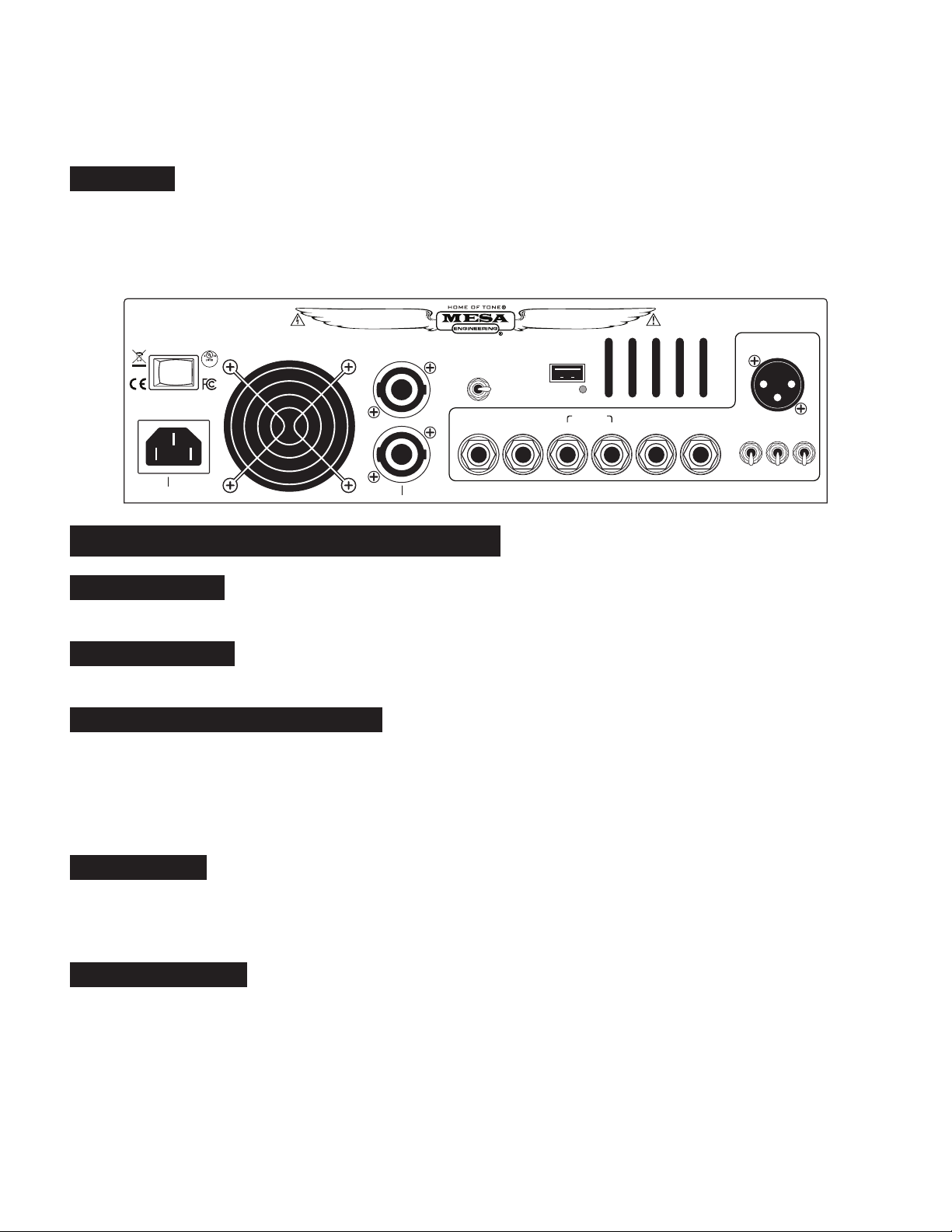
OVERVIEW: REAR PANEL
On the rear panel, you will find the power switch, and the AC mains inlet on a standard IEC “C14” connector. The SUBWAY WD-800
contains an auto-ranging universal power supply that can accept and operate on any voltage between 100-120 volts & 220-240 volts
AC, 50/60Hz without the need for any user adjustments or fuse change. This feature makes these amps ideal for the international
touring musician who plays in a variety of global regions. The only thing necessary to make the amp work is a correct power (mains)
cable that matches the power outlet/receptacle in the region. It is important for the mains power to be grounded/earthed for safety as
well as EMC reasons.
Next are parallel connected NL-4 SpeakOn™ connectors, which are wired with the amplifier positive to terminal “1+” and the amplifier
negative to terminal “1-“. All cables with NL-2 connectors (2 pole) will be wired this way. There is an IMPEDANCE SELECTOR switch
provided to properly match the power amplifier to the load. When driving a load less than 4 ohms (like 2.66 ohms or 2 ohms), set the
impedance switch to the 2 ohm position.
The SUBWAY WD-800 is equipped with a HEADPHONE output, which will drive all common headphones and IEM ear pieces between
8 and 32 ohms, a MUTE/PEQ BYPASS footswitch jack that mutes the signal when the tip is shorted to the sleeve and bypasses the
parametric eq when the ring is shorted to sleeve. Additional connections are provided for a serial master EFFECTS LOOP, an AUX
input, and a TUNER output.
One feature that sets your new SUBWAY WD-800 apart from the rest of the market is the inclusion of a studio grade XLR balanced
DIRECT OUTPUT, complete with PRE-EQ/POST-EQ signal routing switch, MIC/LINE level switch, and pin 1 GROUND LIFT switch.
Circuit attributes include full phantom power protection, high RFI immunity and extreme tolerance to ground potential differences.
Another unique feature is the inclusion of a USB charging port, which allows you to charge most USB connected devices. This can
be handy when rehearsing with an MP3 player, tablet, or phone.
PAGE 2
Page 7

INSTANT GRATIFICATION:
The SUBWAY WD-800 is about the easiest amp on the planet to get great sound from… it really is a “plug and play” amp. Start with the
MUTE switch down (mute off), the ACTIVE/PASSIVE switch down (passive pickup), the HIGHPASS FILTER set to the 9:00 position,
BASS, PASSIVE MID and TREBLE controls in the “flat” (12:00 straight up) position, the MASTER volume control in the 1:00 position
and set the POWER AMP DAMPING control to the HIGH position. Plug your bass in, and turn the GAIN control up until you reach
your desired volume. Then, set the HIGHPASS FILTER, and EQ to taste.
POWER
O/D
INPUT
2.6KHZ
500HZ 1.3KHZ
ACTIVEMUTE
HIGHPASS
PASSIVEPLAY
FILTER
BASS
80HZ 1KHZ
0 dB
150HZ 2.5KHZ 300HZ 5KHZ
0 dB
PEQ
BYPASS
PASSIVE
0 dB
MID
TREBLE MASTERINPUT
2 OHMS
PROTECT
LIMIT
POWER AMP
DAMPING
2-STAGE CLASS A TUBE PREAMPLIFIER
25HZ 125HZ
-12 +12 LOW
-12 +12
PARAMETRIC EQUALIZER
-12 +12
SUBWAY® WD-800
HIGH
MED
™
FRONT PANEL (CONTROLS & FEATURES)
INPUT JACK:
amp of the SUBWAY WD-800. This stage is inherently transparent, and directly feeds the DI out when the DI out is set to the “PRE-EQ” position.
MUTE SWITCH:
the TUNER OUT jack for silent tuning with a tuner connected to the instrument cable and then through to the amp or to the TUNER
OUTPUT jack. When the switch is in the up position, the red LED will illuminate and NO audio will be present at the DIRECT OUTPUT
jack, HEADPHONE jack, or the SPEAKER OUTPUT jack. This switch can also be used to place the amp into standby mode before
and between sets without adjusting any of the controls. When using the MUTE FOOTSWITCH, this switch must be placed in the
down position.
ACTIVE/PASSIVE SWITCH:
buffer. Often (though not always), an active bass may have a signal level up to 10dB greater than a typical passive bass. If you find
that you are operating the gain control near the low (counter-clockwise) end of the control’s rotation in order to prevent the O/L LED
from flashing, switching this switch up (into the ACTIVE position) will reduce the input sensitivity (gain) by ~10dB, allowing greater
control range and freedom from overload with high output active basses. This control does not lower the input impedance of the
amplifier, nor does it “suck tone” like the input pads on some other amps.
This 1/4” (6.35mm) TS (tip-sleeve) jack is the instrument INPUT that feeds the first stage monolithic J-FET input buffer
This switch (and its associated red indicator/tally LED) mutes the audio signal being sent to all outputs except
This switch (and its associated blue indicator/tally LED) sets the sensitivity of the J-FET input
INPUT CONTROL & O/D LED:
This control determines the overall gain (and drive level) of the hybrid J-FET 12AT7 (or
12AU7) vacuum tube gain stage. Overdriving this gain stage may be a desirable tonal characteristic of your playing style, the amber
O/L LED provides a visual indication of the status of the drive signal level and how much preamp overdrive is being achieved. When
using significant overdriven tones, you may find it helpful to back down on the TREBLE EQ a little bit to reduce harshness and also
to reduce the BASS EQ (and/or increase the frequency on the high pass filter) to increase the clarity and impact. This hybrid tube
gain circuit draws inspiration from elements of our legacy amps, including the Walkabout, Carbine, and even the legendary Bass 400.
If it’s your tone, this tube gain stage is designed to be overdriven, so give it a try. When employing heavier overdrive, it’s generally
more pleasing reduce the tweeter level if your cabinets have tweeters. Note that the GAIN control operates in a linear fashion, an
increase in gain continues linearly throughout the entire rotation of the control. The amount of overdrive is increased by turning the
INPUT CONTROL up beyond the clean area of operation, and the overall volume will be controlled by turning the MASTER VOLUME
down as needed.
HIGHPASS FILTER:
This control sets the low frequency roll-off point of the amplifier, and is an important feature in maintain-
ing control over the extreme low end (especially under high drive conditions). This precision filter is comprised of variable two pole
PAGE 3
Page 8

filter with a turnover frequency that is set at approximately 25Hz. While HPF’s have been standard fare within the pro audio industry
for decades, this feature has only appeared in bass guitar amplifiers within the past few years (with some notable exceptions). This
filter provides additional mechanical protection to the speakers from over-excursion damage by reducing the power to the speaker
below the frequency range that the speaker cabinet provides adequate acoustic loading to the drivers. This is one of the primary
(and preventable) causes of premature speaker failure, especially with compact speaker cabinet products that are driven very hard.
A second use for this filter is to roll off the very low end when overdriving the amp. This prevents the signal from becoming muddy,
and preserves the naturally musical growl and grit of the overdriven signal. A third use is for rolling off the extreme low end when
boosting the bass eq control, allowing for some unique low mid voicings, and a fourth use is for reducing the sub-bass frequencies
that can get out of hand in a boomy room. Experimentation will be helpful in all of these applications.
BASS CONTROL:
relative to the rest of the spectrum. Low frequencies (<80Hz) are responsible for the “depth”, “bottom”, “roundness”, or “feel” of the
tone. This is an active control with boost and cut, the amount of boost proportional to the clockwise rotation to the right of “flat” (12:00
straight up) position and the amount of cut proportional to the counter-clockwise rotation to the left of “flat” (12:00 straight up) position.
As with everything related to EQ, generally, a little bit goes a long way. The HIGH PASS FILTER control, combined with the BASS
CONTROL adds another dimension of tone sculpting by rolling off the extreme low end when boosting the bass eq control, allowing
for some unique low mid voicings. Use enough to get the job done and no more. Note that if you have very compact cabinets and
need high volumes, you will want to be aware that it is possible to overdrive speakers with excessive bass boost. If your speaker is
not getting you enough high level low end, it’s possible that you do not have enough “rig for the gig”, and “more speaker” is needed.
This is a shelving type filter.
TREBLE CONTROL:
nal, relative to the rest of the spectrum. High frequencies (>2.5kHz) are responsible for the “bright”, “airy”, “shimmery” character of
the tone. This is an active control with boost and cut, the amount of boost proportional to the clockwise rotation to the right of “flat”
(12:00 straight up) position and the amount of cut proportional to the counter-clockwise rotation to the left of “flat” (12:00 straight up)
position. This is a shelving type filter.
This active eq control is responsible for the amount (or volume) of low frequencies present in the signal,
This active eq control is responsible for the amount (or volume) of high frequencies present in the sig-
PARAMETRIC MID EQ CONTROLS:
GAIN CONTROLS: These controls (bottom row) are responsible for the amount (or volume) of the corresponding LOW MID, MID
and HIGH MID midrange frequencies present in the signal, relative to the rest of the spectrum. (the center frequency of each band
is selected with the corresponding mid frequency control, top row). This is an active control with boost and cut, the amount of boost
proportional to the clockwise rotation to the right of “flat” (12:00 straight up) position and the amount of cut proportional to the counterclockwise rotation to the left of “flat” (12:00 straight up) position of. This is a peak-dip (or bell) style filter. Remember that a little eq
goes a long way, use just enough to get the job done.
FREQUENCY CONTROLS: These controls (top row) are responsible for selecting the center frequency (or pitch) that the corresponding EQ GAIN controls acts on. Rotating this control sweeps the center frequency from lower (counterclockwise) to higher (clockwise).
If the eq gain control is set at 12:00 noon, there will be no effect when rotating the frequency control because there is no boost or
cut being performed. Sweep range varies by band, band 1: 80Hz – 1kHz, band 2: 150Hz – 2.5kHz, and band 3: 300Hz – 5kHz. The
frequency distribution of the sweep control is linear from endpoint to endpoint. It should be noted that these controls do not act on a
single frequency but act on a range of frequencies approximately 1/3 of an octave on each side of the center frequency.
PASSIVE MID CONTROL:
of midrange frequency content present in the signal, relative to the rest of the spectrum. Midrange is primarily responsible for voicing and articulation character of the instrument. This is a passive control with cut only, the amount of cut roughly proportional to the
counter-clockwise rotation of the control. Due to the specific way this filter is implemented by the use of make-up gain, most users
will find that their flat or neutral tone will be from the 10:00 to 2:00 position, and this might give the appearance of boost as the control
is rotated farther clockwise. This filter’s Q (width) symmetry and response is quite different from the parametric mid section, which is
typically used more for precise tuning of the amp’s response.
MASTER VOLUME CONTROL:
This eq control is an integral part of the amplifier’s voicing circuit and is responsible for the amount
This control is responsible for the level of signal being sent to the power amp, and deter-
PAGE 4
Page 9

mines the overall playing volume of the SUBWAY WD-800. Using the MASTER VOLUME along with the INPUT GAIN control allows
the optimal control over playing volume. For example, if you are using high input gain to achieve an overdriven tone, it will be likely
be necessary to adjust the master volume down to obtain a reasonable playing volume and to avoid excessive overdriving of the
power amp. Likewise, if you are looking for a very clean tone, you may wish to start with a lower INPUT GAIN control setting and use
a higher MASTER VOLUME control setting to obtain the desired playing volume. The MASTER VOLUME control operates in a linear
fashion, an increase in volume continues linearly throughout the entire rotation of the control.
POWER AMP DAMPING CONTROL:
speaker. Because this is an unusual, but very useful control, some discussion of what damping is will help you understand why this
control may be so important to some players.
One of the primary differences between solid state and tube amps is how tightly the speaker is coupled to the power amplifier’s output
stage. All amplifiers have some resistance (more correctly, impedance) between the power circuitry and the speaker. This impedance
greatly affects how tightly the amplifier can control the speaker. High damping means that there is very little impedance between
the amplifier’s output circuitry and the speaker, the feel will be tighter and more controlled. Low damping means that there is more
impedance between the amplifier’s output circuitry and the speaker, the feel will be looser and less controlled. Because a speaker is
a complex impedance, this “lower damping” interaction can be responsible for a bit more “bloomy”, organic feel.
Generally, tube amps fall into the low damping category while solid state amps fall into the medium to high damping category. Speakers
have mass and the force required to accelerate the mass back and forth comes from the power generated by the amp and delivered
through the voice coil sitting within the magnetic gap of the speaker’s motor. This means that to accurately accelerate and decelerate
the cone at each end of its travel requires efficient power delivery to the speaker. As the power delivery becomes less efficient, the
force becomes less and the cone accelerates and decelerates more sluggishly, corresponding to undershoot and overshoot of the
cone. This, plus native voicing, are the most likely explanations for the “bloomy”, slightly “round bottom” feeling reputation that many
tube amps enjoy.
In tube amps, the impedance between the output stage and the load is high (resulting in a low damping factor of maybe 25) while in
a solid state amp the impedance between the output stage and the load is low (resulting in a high damping factor of maybe 500 to
1000). These are inherent properties of the respective topologies. These damping factor numbers also vary with frequency, as does
the speaker impedance, so the interaction is quite complex actually.
This control is responsible for amount of damping that the amplifier places on the
What does this mean? With lower damping, the amp will tend to feel a little looser (especially on the low end), a little bloomy, and a
little more organic. While there will be some tonal differences, it’s really more of a feel difference. With higher damping, the amp will
feel a little tighter and more controlled on the bottom end, and to some players it may feel more “immediate”. This control allows the
player to adjust the damping to accommodate a wider range of tastes. In general, the lower damping will work better at lower volumes
and the higher damping will work better at higher volumes (especially in a boomy room) where better cone control and tighter low end
might help the bass fit better into a mix. Because amplifier damping interacts with speaker impedance, different speakers will behave
differently. As a generality, a sealed cabinet, which has high intrinsic electro-mechanical damping will probably feel a little better with
a lower amp damping. A ported cabinet on the other hand typically has lower intrinsic electro-mechanical damping and will probably
feel a little better with a higher damping. There are some ported cabinets with tunings that result in a serious under-damped response
and these cabinets in particular tend to work better with the highest damping. Let your ears and fingers be the ultimate judge. It should
be noted that the effect is very speaker dependent, and somewhat subtle. This feature is simply another tool to allow “feel based”
players a little more control under a wider variety of playing conditions when necessary.
POWER LED:
If this LED is not on, double-check the power source, and be sure the power cable is firmly inserted into the IEC power inlet socket.
2 OHM LED:
located on the rear panel.
PROTECT LED:
ternal fault (such as blocked ventilation, shorted speaker cable or defective speaker), or that there is an internal fault within the amp
This blue LED indicates that the amplifier is connected to a power source and is switched on, operating correctly.
This blue LED indicates that the amplifier’s 2 ohm operating mode has been selected via the 2 OHM switch
This red LED indicates that the amplifier has entered protect mode and is either protecting itself from an ex-
PAGE 5
Page 10
itself. Verify that it’s not a fault external to the amplifier by disconnecting all cables (except the power cable) from the amplifier. If the
BASS
500HZ 1.3KHZ
PARAMETRIC EQUALIZER
2-STAGE CLASS A TUBE PREAMPLIFIER
2.6KHZ
TREBLE MASTERINPUT
HIGHPASS
FILTER
POWER AMP
DAMPING
PASSIVE
MID
INPUT
25HZ 125HZ
80HZ 1KHZ
0 dB
-12 +12 LOW
MED
HIGH
0 dB
-12 +12
0 dB
-12 +12
150HZ 2.5KHZ 300HZ 5KHZ
PEQ
BYPASS
POWER
PROTECT
2 OHMS
LIMIT
O/D
PASSIVEPLAY
ACTIVEMUTE
SUBWAY® WD-800
™
protect LED is no longer lit, the problem is most likely a bad speaker cable or defective speaker. Testing with a set of headphones
can help to narrow down the problem, as the headphone signal is derived post-power amp using a frequency compensated, cabinet
emulation network.
LIMIT LED:
This amber LED indicates that the power amp is nearing maximum power and is entering the soft clip/limit output
tube emulation mode. Soft clip/limit output tube emulation mode mimics many of the desirable characteristics of tube amp output
stage overdrive while eliminating the common solid state clipping artifacts. There is approximately 6dB of range on this circuit, driving
beyond this, of course, will cause gradual output stage clipping. It’s acceptable for this amplifier to operate in output stage overdrive
mode (if that’s the tone you are after) with the LED flashing roughly 25% of the time on.
CAUTION:
Risk of Electric Shock. Do Not Open.
No user serviceable parts inside.
POWER
100V-240VAC
~50/60Hz
AMPLIFIER
OFF ON
MAX AVG PWR CONSUMPTION 400W
MAINS FUSE: INTERNAL T-6.3A/250V
INPUT
POWER
44YV
MADE IN PETALUMA, CA, USA WITH THE WORLD’S FINEST MATERIALS
SPEAKER OUTPUTS
IMPEDANCE
2 Ω 4/8 Ω
HEAD
2 OHM MINIMUM LOAD
400 WATTS/8 OHM
RATED
800 WATTS/4 OR 2 OHM
POWER
PHONES
MUTE/PEQ BYP
REAR PANEL (CONTROLS & FEATURES)
POWER SWITCH:
This switch is used to turn your amp on and off by disconnecting the amplifier from the power source
WARNING:
Replace fuse with same type/rating only.
Do not expose to rain or moisture.
USB DEVICE PWR
USB
POWER ON
(FOOTSWITCH)
RETURN SEND
SUBWAY
FX LOOP
®
WD-800™ BASS AMPLIFIER
AUX
INPUT
TUNER
OUTPUT
TUBE TYPE: 12AT7
CATHODE BIASED CLASS A
DIRECT OUTPUT
(PHANTOM POWER PROTECTED)
LEVEL
SOURCE
POST-EQ
PRE-EQ MIC GROUND
PIN 1
LINE
LIFT
(mains). This amplifier complies with the new EU Eco-design directive by providing a switched “0.00 watt power consumption off-mode”.
IEC POWER INLET:
This power inlet conforms to the IEC C-14 type standard, and is to be used with a cordset containing a
matching connector, and appropriate plug for the intended market.
OPERATING POWER REQUIREMENTS:
The SUBWAY WD-800 is designed with a universal, auto-ranging power supply
that automatically adjusts to line voltages between 100-120V and 220-240V, 50 or 60Hz. The power supply is internally monitored
by supervisory protection circuits and thus contains a non-user replaceable fuse that opens in the unlikely event of a major failure.
The amplifier is designed to be use with grounded or earthed power, meaning that the chassis is always maintained at ground/earth
potential even in the event of a gross failure within (or external to) the amplifier. Never remove the grounding/earthing pin from the
power plug, or alter the power cable.
COOLING FAN:
loads (including 2 ohms) at very high duty cycles. Be sure this fan inlet is not blocked or the amplifier’s protection circuits shutting the
amplifier down due to a thermal fault condition. This quiet, low noise fan will always run at a low speed, the air flows into the chassis
The SUBWAY WD-800 incorporates a low speed, high reliability cooling fan which allows it to drive difficult
from the back and out through the front and side slot vents.
SPEAKER OUTPUTS:
The SUBWAY WD-800 is rated to drive a minimum 2 ohm load (with the impedance selector switch
set to the 2 ohm position), meaning either 4 x 8 ohm cabinets or 2 x 4 ohm cabinets. The amplifier incorporates a pair of SpeakOn™
NL4FC connectors (wired in parallel) that mate with either NL2MP or NL4MP plugs.
Cables using NL-2 plugs contain only 1+/1- terminals and will always be correctly wired for use with the amplifier, but cables using NL4
connectors come with different wiring configurations. If using cables with NL-4 connectors, they may be constructed with standard 2
wire cable which must be wired 1+ to 1+ and 1- to 1-. If the cable contains 4 wires, that’s ok because terminals 2+ and 2- which are
PAGE 6
Page 11

connected to the second pair are simply not used.
The cables to avoid are what are called NL4 bridge mode cables, which are typically 2 wire, and wired 1+/1- on the speaker end and
1+/2+ on the amplifier end (used for pro audio power amps that support this specific bridged termination). These cables SHOULD be
clearly marked but sometimes they are not, so be aware of the possibility when buying or troubleshooting cables.
Why SpeakOn™ cables and not the “old favorite” ¼” (6.35mm) connector? There are several important reasons, the first being that
with updates to global safety regulations, amplifiers like the Subway WD-800 require “touch-proof connections”. A second reason is
because the power amplifier’s internal topology is BTL (bridge tied load), neither output terminal are at ground potential, so touch-proof
connectors provide an added layer of safety to the system. A third reason is the often poor quality of the 1/4” (6.35mm) connection,
which at low power is not much of an issue, but at higher power levels become a failure point. A fourth reason is that one common
failure mode of amplifiers is when the 1/4” (6.35mm) speaker cable works loose at the speaker cabinet, the tip gets shorted to the
sleeve within the speaker jack’s bushing, applying a short circuit to the amplifier’s speaker output. While this amplifier is protected
against such faults, it’s not good practice to test any amplifier protection on a regular basis.
Never connect the speaker output to anything except a speaker. This especially means not to a DI, even a speaker level DI
because the Subway WD-800 utilizes a BTL (bridged) output power amplifier. On a bridged amplifier, the minus terminal that
is normally at ground is actually a driven output that swings above and below ground at peak currents of up to 30 amps. Using a
DI, the normal shell or ground terminal (pin 1) of the DI is not at ground at the amplifier’s end but may be connected to the console
(mixer) circuit ground bus at the console’s end which would cause the amplifier to drive dangerous currents into circuitry that does
not expect to see such currents, nor is it generally protected from this fault. So, in addition to possibly damaging your amp, you could
also damage a (potentially) very expensive console.
SPEAKER IMPEDANCE:
that the amplifier is tasked with delivering. The lower the speaker’s impedance, the greater the current that the power amplifier must
provide. The lowest impedance that the Subway WD-800 amplifier is capable of driving safely is 2 ohms (with the impedance selector
switch in the 2 ohm position), which is a parallel connection (the standard connection of virtually all speaker cabinets) of either two
x 4 ohm cabinets or four x 8 ohm cabinets. Note that measuring speaker cabinets using an ohm meter will not give accurate results
because ohm meters read DC resistance not AC impedance (technically called “reactance”). AC impedance will always be greater
than the DC resistance, an 8 ohm speaker will typically measure between 5 and 7 ohms, a 4 ohm speaker will typically measure
between 2.5 and 3.5 ohms when measured with an ohm meter (or DMM).
SPEAKER POLARITY (OR PHASE):
dustry standard will move forward when a positive DC voltage is applied to the positive terminal of the speaker. While there are well
established standards, there are also deviations from standards, either by legacy (ie. early JBL drivers), by faulty repair (incorrectly
wired cabinet or defective recone parts) or a manufacturer choosing to ignore the standard. If a multi-driver speaker cabinet or a pair
of speaker cabinets does not appear to have the expected output or low end, it’s always a good idea to double-check that all drivers
move forward with positive DC voltage (no more than a 9 volt battery) momentarily applied to the + terminal (this will be the 1+ terminal
on a SpeakOn™ connector, or the tip on a 1/4” (6.35mm) connector). If you find that on a multi-speaker cabinet, one speaker moves
out while the other does not move, it’s likely that the non-moving driver has either failed or has become disconnected. If one driver
moves out while the other driver moves in, it’s likely that the driver moving in is wired incorrectly (or in a sealed cabinet is failed or
disconnected and is merely being moved in the opposite direction by coupling to the air mass inside the cabinet itself). Being aware
of these possibilities can often help when troubleshooting something that doesn’t appear to be performing quite right.
IMPEDANCE SELECTOR SWITCH:
amplifier’s drive capabilities to loads below 4 ohms. Whenever using loads of either 2.66 ohms (a 4 ohm load paralleled with an 8
ohm load or three paralleled 8 ohm loads) or a 2 ohm load (a 4 ohm load paralleled with a 4 ohm load or four paralleled 8 ohm loads)
this switch must be set in the 2 ohm position. Failure to do so will result in the amplifier’s protection circuits (correctly) shutting the
amplifier down due to an over-current fault condition.
All speakers have a “rated nominal impedance”. Impedance is the resistance to AC electrical current
All speakers have “polarity”. A speaker that is wired in accordance to the current in-
The SUBWAY WD-800 is equipped with an impedance selector switch to match the
PAGE 7
Page 12

HEADPHONE OUTPUT:
will drive all common headphones and IEM ear pieces between 8 and 32 ohms (and many well above 32 ohms). It is not necessary
to have a speaker connected to the amp when using headphones, it is completely safe to operate the amp without a speaker
load. It’s advisable to use caution whenever sticking a sound source in your ear, as damaging volume is possible, especially with
“bass player accidents”, and when volume is factored over a long period of time. This output contains additional cabinet emulation
circuitry. This output should not be connected to anything but headphones or ear buds.
The SUBWAY WD-800 includes a 1/4” (6.35mm) TRS tip-ring-sleeve headphone output jack, which
MUTE / PEQ BYPASS FOOTSWITCH:
standard latching two button footswitch terminated with a 1/4” (6.35mm) tip-ring-sleeve plug. When the TIP is shorted to the sleeve,
the signal is muted. (Note that the front panel mute switch must be in the down position for this function to work, otherwise, the front
panel switch over-rides the footswitch by placing the amp in mute mode regardless of the position of the footswitch). When in the
mute mode, the signal is available only at the tuner output jack, the signal is muted at the speaker output, headphone output, effects
send output and DI output. When the RING is shorted to sleeve, the 3 band parametric eq. is bypassed and the red PEQ BYPASS
LED will illuminate on the front of the amp (indicating that the parametric eq is bypassed). MESA sells Subway WD-800 specific
footswitches (two button) separately through our authorized dealers and distributors, our parts and accessories online store, or by
contacting our customer service department.
EFFECTS LOOP:
for connecting “serial” line level outboard effects devices such as compressors, limiters and gates. The loop may also be used with
parallel outboard devices such as delays, reverbs, harmonizers and octavers, etc. by using the wet-dry mix control on the outboard
device to mix the dry with processed signal. This loop is located right before the master volume control, and is also intended to be
used as a PREAMP OUT / POWER AMP IN for the linking of two amplifiers in a master-slave configuration, or for using the preamp
or power amp separately. The master volume control on each amplifier is then used to set the volume between the two amplifiers (in
a master/slave configuration), or as a power amp input level control when using the Subway WD-800 as a stand-alone power amp.
The effects loop’s return jack contains a “normal switch” that interrupts the signal whenever a plug is inserted into the return jack, and
automatically bypasses the effects loop when the plug is removed. Because of this, the effects send jack may be used as a post eq,
pre master volume output, even when the amp is not being used as a loop.
AUX INPUT:
channels from an MP-3 player. i-device, or laptop as many of these new devices do not contain adequate circuitry for proper summing. The signal injection point is right before the master volume control, you can use the player’s volume control to balance the
level between your bass and the playback device. Note that for best performance, a 1/8” (3.5mm) TRS to 1/4” (6.35mm) TRS cable
(also called a stereo cable) is used, this will always match between devices and allow the amplifier’s automatic summing circuitry to
work properly. For upright players, this input can be used to plug the output of your upright’s outboard preamp (such as our Rosette,
Subway or Subway Plus PRE-DI) into the power amp. The level of this input is controlled by the master volume on the SUBWAY
WD-800 as well as the controls on your outboard preamp.
A serial (series) effects loop is provided, consisting of 1/4” (6.35mm) TS effects send and effects return jacks,
This amplifier is provided with a 1/4” (6.35mm) TRS AUX input. This TRS stereo jack properly sums left and right
This dual function 1/4” (6.35mm) TRS footswitch jack is used in conjunction with a
DIRECT OUTPUT (DI OUT):
sion of a studio grade XLR balanced direct output. This output is capable of driving balanced analog lines as long as 500 feet, is fully
phantom power protected, is noise resistant and stability compensated for a reliable, low noise floor, high quality signal. This output
follows the pro audio standards of pin 2=non-inverting, pin 3=inverting and pin 1=ground. Every known console in the world follows
this wiring standard.
DI OUT SOURCE SWITCH:
the PRE position, the signal is sourced directly from the input buffer. Muting the amplifier by the front panel mute switch (or optional
footswitch) mutes this output to allow for silent tuning. In the POST position, the signal is sourced from the output of the equalizer
section and before the master volume control. Generally, for PA use the FOH (front of house) engineer will probably prefer a PRE
eq send because the capability of his PA system may be significantly different than your stage rig, and the eq that you use to sound
good on stage may not work well on a bigger system and in a larger acoustic space out front, or in the context of the mix. If you use
the overdrive capability of the amp, or you use effects in the effects loop, then the post position is a better choice but you will need to
work with your FOH engineer to ensure that the eq you use on stage will work ok for the FOH mix. For recording, depending on the
A feature that sets your new SUBWAY WD-800 apart from the rest of the market is the inclu-
This switch selects the signal source routing that is used to derive the direct output signal. In
PAGE 8
Page 13

tracking goals of the engineer, either PRE or POST might be used. When using the amp as a preamp (into a pro audio power amp
or powered PA cabinet for example), generally the POST position would be used and line level would be selected (unless using a
powered speaker that can accept mic level signal).
DI OUT PIN 1 LIFT:
connector. Balanced outputs do not rely on the pin 1 or shield connection to transmit signal to the console. While pin 1 is always connected to the console’s master ground bus, sometimes (due to differences in potential of a building’s ground/earth system) currents
will flow between grounds if there is a common connection, resulting in hum. By lifting the ground at the source (bass amp) end, this
allows the shielding to the console’s input to remain in place while breaking the ground current flow that is responsible for inducing
hum into the audio signal carrying pair of conductors. One thing that complicates this is that at very high (radio) frequencies, ground
is not “really” ground, so additional techniques are incorporated within this network that allows 2 simultaneously functional grounding
spectrums within the same network, providing added RFI (radio frequency interference) rejection. The general rule is to start with
pin 1 lifted, and if there is noise, try connecting it and see if the noise level drops. It should also be noted that there are a lot of other
possible causes for noise, this switch is only a solution for ground loop noise between the PA and the bass amp.
USB DEVICE POWER:
cording, jamming or even performing. It may also be used to recharge phones, MP-3 players, iPods, and any number of devices. This
port follows the PC USB 2.0 standard, rated current is 500mA maximum, and conforms to the Apple USB charge current standard.
While this charge port will work with most devices, there are some that do not conform to any current demand/limit standards or must
be operated from a high current (or proprietary) USB charge port only. These devices will either charge more slowly or possibly not
at all. Due to the lack of uniformity in the market following standards, and continual evolution/changing of the standards, this port is
offered as a convenience only.
This switch connects or lifts the circuit ground/earth/common connection from pin 1 on the XLR DI OUT
This connector provides power to USB devices that might be used in conjunction with practicing, re-
PLAYER NOTES AND REMINDERS:
PAGE 9
Page 14

DISCUSSION ABOUT SMPS & CLASS D FROM THE DESIGN TEAM:
QUESTION:
ANSWER:
decrease the size and weight. These designs are carefully implemented and fully tested to insure robust, reliable performance in real
world conditions night after night.
QUESTION:
ANSWER:
has to accommodate reactive load inefficiencies, overly sensitive protection of “safe operating areas”, and dissipate waste heat like
output devices operating within their linear region. This means more power and better low frequency control with less heat. The pro
audio industry has been using this technology almost exclusively in the large scale touring market for about 20 years, driving massive
arena and stadium subwoofers night after grueling night on the road. In fact, much of the technology in our power amplifiers comes
from the high reliability touring pro audio world.
QUESTION:
ANSWER:
fiers as well as in touring pro audio. We have worked closely with the European engineering team on the development of these new
power modules, including extensive testing, on real world stages with real musicians and real audiences, night after night, as proven
by the reputation of the entire Subway bass amp line. This engineering relationship goes back over 20 years, when class D amplifiers
were in their infancy.
What makes this new amplifier so light weight?
This amplifier uses new technology, both an SMPS (SwitchMode Power Supply) and a Class D power amplifier to
How can such a light weight amplifier deliver solid bass? I thought an amp has to be heavy to produce deep bass.
By operating in a non-linear fashion (with power devices that are either fully on or fully off) the output stage no longer
How do I know that these amplifiers will be reliable?
The designer of the Subway amplifier project has over 20 years of SMPS/Class D amplifier experience, in bass ampli-
QUESTION:
ANSWER:
than a traditional power supply (either 50Hz or 60Hz). A high operating frequency reduces the size of the transformer’s core, which
in turn reduces the length of the wire wound around the core. Since most of the weight of a power transformer is in the core and the
copper wire, reducing the core reduces size, weight and the amount of copper needed to wrap around the core, which improves the
performance of these smaller transformers under the highest load conditions.
QUESTION:
ANSWER:
a high voltage direct current (HVDC). This HVDC is then filtered/stored in the input filter capacitors as reserve energy for discharge as
needed into dynamic loads. This HVDC is then chopped/switched at about 100kHz into high voltage, high frequency alternating current
(HVHFAC), which is fed through a high frequency transformer which converts the HVHFAC into low voltage, high frequency alternating
current (LVHFAC) which is then rectified and filtered into low voltage direct current (LVDC) that the power amplifier’s circuitry uses.
QUESTION:
ANSWER:
or fully off at a switching frequency of about 500kHz. This “cutoff-saturation” switching minimizes waste heat by avoiding operation in
the wasteful “linear range”, and without the heat, there’s no need for the large, heavy aluminum heatsinks.
Why is the power supply so small and light weight?
An SMPS is just like any other power supply, except for the fact that it operates at a much higher frequency (~100kHz)
How does the SMPS work?
Without getting too technical, a switch-mode power supply takes the incoming AC mains (50-60Hz) power, rectifies it to
Why is the Class D power amplifier so small and light weight?
A Class D amplifier operates its output stage non-linearly, meaning that the output devices are switched either fully on
QUESTION:
How does the Class D amplifier work?
PAGE 10
Page 15

ANSWER:
tion of the analog audio signal (similar to the A/D converter in a PWM digital audio recorder) at +5 volts conventional logic level. This
PWM signal is level shifted upwards by large switching power MOSFET transistors (that operate non-linearly to avoid waste heat) to
high voltage and current. The resulting high level PWM signal then passes through a high power “low pass reconstruction filter” that
extracts the original but level shifted (amplified) audio signal from the PWM signal which feeds your speakers. Class D is not “digital”,
it is a non-linear analog technology, sharing some fleeting similarities with its digital counterpart. (Disclaimer: This is a simplified
description, there are many details omitted, but the basic operational function is accurate. There is a lot of engineering that goes into
making a high performance, robust, safe and reliable design.)
In Class D amplifiers, the analog audio signal is converted into a PWM (pulse width modulated) pulse train representa-
TROUBLESHOOTING:
In the event that your amplifier appears not to work correctly, often enough the problem is not with the amp, but a related piece of
equipment, so it’s necessary to take a deliberate, systematic approach to troubleshooting in order to effectively identify and correct
the problem. Yes, believe it or not, we have seen all of these things many times.
SYMPTOM:
Is the power LED lit and do the tally LEDs over the function switches work?
NO: Possible causes to check in this order are
1. Verify the power source, verify that the IEC power cable is not damaged and is fully inserted into its socket,
2. Verify that nobody unplugged your amp or turned off your power strip when you weren’t looking (if so, blame the guitar player,
turn on and play.).
3. If these do not solve your problem, it’s possible that your amplifier has failed so call our customer service department and we
will help you get this resolved.
YES: Possible causes to check in this order are:
1. Defective speaker cable or cabinet (test known good speaker cable and cabinet)
2. Defective bass or cable (test with known good bass and instrument cable)
3. Defective pedals/effects/pedalboard (plug bass directly into amplifier input, bypassing all devices in front of the amp)
4. Mute switch engaged or mute footswitch turned on (turn mute function off)
5. Problem with effects loop (for models with effects loop, a cable plugged into the effects return will interrupt signal, there is a
problem with an effects device or patch cable, there is an intermittent connection due to dust or debris inside the effects return
jack. Try bypassing effects loop with short shielded patch cable.
6. Gain or Master controls turned down (turn the controls up)
No audio output:
7. Will the amp play with a signal fed into the AUX INPUT or EFFECTS RETURN jacks? If so, the problem is with the preamp.
It’s possible that the tube/valve has failed. (substitute a known good 12AT7 or 12AU7 into the V1 position and see if this
restores audio)
8. There is indeed a problem with the amp, call our customer service department and we will help you get this resolved.
SYMPTOM:
1. Defective battery in active bass causing instrument’s onboard preamp to distort (replace battery)
2. With very hot 18V basses, it’s possible to overdrive the amp’s preamp when in passive mode (switch to active mode)
3. Gain structure problem if using effects (if the amp has an effects loop, which operates at line level, it’s possible to overdrive
some effects that are built exclusively for instrument level. Try unplugging effects from effects loop.)
4. Slightly intermittent cable in system (this can be an instrument cable, patch cable or loose screw in SpeakOn plug)
Distorted audio output:
PAGE 11
Page 16

5. Defective or blown speaker(s) in cabinet (test with known good cabinet, repair cabinet as needed)
6. Possible failing tube/valve in preamp (substitute with known good 12AT7 or 12AU7)
7. There is indeed a problem with the amp, call our customer service department and we will help you get this resolved.
SYMPTOM:
1. Defective instrument cable or problem with bass wiring (unplug instrument cable from amplifier, if hum goes away, this means
that the noise is entering from outside the amplifier. Try known good instrument cable and/or bass)
2. Problem with wiring or a device in the effects loop (remove send and receive wiring from the amp’s effects loop to identify the
source of the noise, correct as necessary.)
3. Power source wiring is not grounded/earthed (check all wiring for missing grounding/earthing pins, have qualified electrician
check building power wiring for missing ground/earth connections and correct as necessary.)
4. External stray magnetic field present coupling into the pickups, especially single coils (one clue that this may be the cause
is when the volume level of the hum changes with position of the bass. Possible causes are large power transformers located
near the performance area, if this occurs when you get close to another instrument amp it may be due to stray field from its
power supply)
5. If your amp model contains a tube/valve in the preamp, it’s possible that you are experiencing the beginning of a tube/valve
failure (replace tube/valve)
SYMPTOM:
1. If the noise goes away when the instrument cable into the amp is unplugged, the cause of the noise is external to the amp
(possibly an active preamp with the treble turned all the way up, a failing battery, defective on board preamp)
2. If your amp model contains a tube/valve in the preamp, it’s possible that you are experiencing the beginning of a tube/valve
failure (replace tube/valve)
Noise (low frequency hum) in audio:
Noise (high frequency hiss and hash) in audio:
3. If there neon or fluorescent lighting close by, it’s possible that EMI is radiating into the pick-up wiring (try turning off such lighting to see if noise goes away. If so, it could be arcing secondary wire on neon lighting, failing ballast or tube on fluorescent
lighting, radiated EMI getting into instrument pick-up)
4. Power source wiring is not grounded/earthed (check all wiring for missing grounding/earthing pins, have qualified electrician
check building power wiring for missing ground/earth connections and correct as necessary.)
5. Problem with wiring or a device in the effects loop (remove send and receive wiring from the amp’s effects loop to identify
the source of the noise, correct as necessary.)
6. Tweeter turned all the way up in a quiet room (may need to turn tweeter down under such conditions, especially if the sensitivity of the tweeter greatly exceeds that of the low frequency drivers with tweeter turned up)
SYMPTOM:
1. Popping while playing, especially one string. (check bass set-up to be sure there is adequate clearances between the string
and pickup pole pieces.)
2. Popping while just sitting there, or when touched. (under dry environmental conditions, it’s possible that electrostatic discharge
is the cause. (try antistatic mat on floor, humidifier in room)
3. Popping when tapping or banging on chassis. If your amp model contains a tube/valve in the preamp, it’s possible that you
are experiencing the beginning of a tube/valve failure (replace tube/valve)
4. Popping or static noise can be caused by some cellular phone devices, especially if they are located close to pickups. Turning
the phone off or setting to “airplane mode” will eliminate this as a cause.
Noise (popping) in audio:
PAGE 12
Page 17

SYMPTOM:
1. Disconnect all cables except power cable, if the amp is no longer in protect, try plugging in just the speaker cable. If the amp
goes immediately into protect, one possible cause is a defective or damaged crossover that is presenting an illegal load to
the simplifier and the protection circuit is working correctly. (try a known good speaker cabinet from another manufacturer to
rule this possibility out. If the amp works correctly with another speaker cabinet, call customer service for assistance. This is
more common with “do it yourself” speaker projects with incorrectly designed crossovers. ALL amps with PWM carriers are
sensitive to stored reactive energy is defective crossover tank circuits.)
2. Protect circuit shuts down amp while playing at low to moderate volumes (possible shorted speaker cable, try known good
speaker cable)
3. Protect circuit shuts down amp at moderate to high volumes. Verify that total load to the amplifier has not fallen below 4 ohms
(or 2 ohms on models that support 2 ohms with the impedance selector switch set to 2 ohms). (possible causes are incorrect
pairing of multiple speaker cabinets, incorrectly labeled speaker cabinets that were repaired or modified without relabeling,
defective driver that has shorted voice coil turns as voice coil warms up.)
4. Power source voltage falling dangerously low due to improper wiring or extension cable that is too long for it’s wire size. (triggering the amp’s under-voltage protection), or from dangerously high power source voltage (triggering the amp’s over-voltage
protection) (correct problems as needed with the help of a qualified electrician)
Protect LED turns on:
SYMPTOM:
1. Is this an Apple device? There are several program controlled charge rates available for Apple products, varying from 100mA
all the way up to 2.1A. The charge port will support the 500mA standard, which will charge the larger devices more slowly
than the bigger dedicated chargers.
2. Is this an Apple i-Pad or other large tablet? When operating an iPad or tablet, the current draw of the screen alone will be
close to 500mA so the charging rate will be very low. Operating with a charged battery and also connected to the charge port
on the amp will greatly extend the battery life under use however.
3. Is this an Android phone that Qualcom QC enabled? This charger does not support QC, and will charge at the slower 500mA
rate if the device software allows it.
4. Does your device use a USB-C connector? While it won’t charge at the higher rate’s supported by this standard, it should be
backwards compatible with the 500mA standard.
No (or slow) USB charging of connected device:
PAGE 13
Page 18

FACTORY SAMPLE SETTINGS
CRISP, CLEAN FINGERSTYLE
O/D
ACTIVEMUTE
HIGHPASS
PASSIVEPLAY
INPUT
2-STAGE CLASS A TUBE PREAMPLIFIER
FAT, FULL & ROUND
O/D
ACTIVEMUTE
PASSIVEPLAY
INPUT
2-STAGE CLASS A TUBE PREAMPLIFIER
FILTER
25HZ 125HZ
NOTE: Bypass Parametric Equalizer
HIGHPASS
FILTER
25HZ 125HZ
NOTE: Bypass Parametric Equalizer
PEQ
2.6KHZ
0 dB
-12 +12
2.6KHZ
0 dB
-12 +12
BYPASS
PEQ
BYPASS
BASS
BASS
500HZ 1.3KHZ
80HZ 1KHZ
-12 +12 LOW
150HZ 2.5KHZ 300HZ 5KHZ
0 dB
-12 +12
0 dB
PARAMETRIC EQUALIZER
500HZ 1.3KHZ
80HZ 1KHZ
-12 +12 LOW
150HZ 2.5KHZ 300HZ 5KHZ
0 dB
-12 +12
0 dB
PARAMETRIC EQUALIZER
PASSIVE
MID
PASSIVE
MID
POWER
2 OHMS
PROTECT
LIMIT
POWER AMP
TREBLE MASTERINPUT
DAMPING
MED
SUBWAY® WD-800
POWER
2 OHMS
PROTECT
LIMIT
POWER AMP
TREBLE MASTERINPUT
DAMPING
MED
SUBWAY® WD-800
HIGH
™
HIGH
™
SLAPTASTIC
O/D
ACTIVEMUTE
HIGHPASS
PASSIVEPLAY
FILTER
INPUT
2-STAGE CLASS A TUBE PREAMPLIFIER
25HZ 125HZ
TUBE GRIND & PUNCH
O/D
ACTIVEMUTE
HIGHPASS
PASSIVEPLAY
INPUT
2-STAGE CLASS A TUBE PREAMPLIFIER
FILTER
25HZ 125HZ
BASS
BASS
PEQ
500HZ 1.3KHZ
80HZ 1KHZ
-12 +12 LOW
150HZ 2.5KHZ 300HZ 5KHZ
0 dB
-12 +12
0 dB
PARAMETRIC EQUALIZER
500HZ 1.3KHZ
80HZ 1KHZ
-12 +12 LOW
150HZ 2.5KHZ 300HZ 5KHZ
0 dB
-12 +12
0 dB
PARAMETRIC EQUALIZER
2.6KHZ
0 dB
-12 +12
2.6KHZ
0 dB
-12 +12
BYPASS
PEQ
BYPASS
PASSIVE
MID
PASSIVE
MID
PROTECT
TREBLE MASTERINPUT
SUBWAY® WD-800
PROTECT
TREBLE MASTERINPUT
SUBWAY® WD-800
POWER
2 OHMS
LIMIT
POWER AMP
DAMPING
MED
POWER
2 OHMS
LIMIT
POWER AMP
DAMPING
MED
HIGH
™
HIGH
™
PAGE 14
Page 19

USER SETTINGS
O/D
ACTIVEMUTE
HIGHPASS
PASSIVEPLAY
INPUT
FILTER
BASS
500HZ 1.3KHZ
80HZ 1KHZ
0 dB
2.6KHZ
150HZ 2.5KHZ 300HZ 5KHZ
0 dB
0 dB
PEQ
BYPASS
PASSIVE
MID
POWER
2 OHMS
PROTECT
LIMIT
POWER AMP
TREBLE MASTERINPUT
DAMPING
2-STAGE CLASS A TUBE PREAMPLIFIER
25HZ 125HZ
O/D
ACTIVEMUTE
HIGHPASS
PASSIVEPLAY
FILTER
INPUT
2-STAGE CLASS A TUBE PREAMPLIFIER
25HZ 125HZ
O/D
ACTIVEMUTE
HIGHPASS
PASSIVEPLAY
FILTER
INPUT
BASS
BASS
-12 +12 LOW
500HZ 1.3KHZ
80HZ 1KHZ
-12 +12 LOW
500HZ 1.3KHZ
80HZ 1KHZ
-12 +12
PARAMETRIC EQUALIZER
150HZ 2.5KHZ 300HZ 5KHZ
0 dB
0 dB
-12 +12
PARAMETRIC EQUALIZER
150HZ 2.5KHZ 300HZ 5KHZ
0 dB
0 dB
-12 +12
2.6KHZ
0 dB
-12 +12
2.6KHZ
0 dB
PEQ
BYPASS
PEQ
BYPASS
PASSIVE
MID
PASSIVE
MID
SUBWAY® WD-800
PROTECT
TREBLE MASTERINPUT
SUBWAY® WD-800
PROTECT
TREBLE MASTERINPUT
MED
POWER
2 OHMS
LIMIT
POWER AMP
DAMPING
MED
POWER
2 OHMS
LIMIT
POWER AMP
DAMPING
HIGH
™
HIGH
™
2-STAGE CLASS A TUBE PREAMPLIFIER
25HZ 125HZ
O/D
ACTIVEMUTE
HIGHPASS
PASSIVEPLAY
FILTER
INPUT
2-STAGE CLASS A TUBE PREAMPLIFIER
25HZ 125HZ
BASS
-12 +12 LOW
500HZ 1.3KHZ
80HZ 1KHZ
-12 +12 LOW
-12 +12
PARAMETRIC EQUALIZER
150HZ 2.5KHZ 300HZ 5KHZ
0 dB
0 dB
-12 +12
PARAMETRIC EQUALIZER
-12 +12
2.6KHZ
0 dB
-12 +12
PEQ
BYPASS
PASSIVE
MID
SUBWAY® WD-800
PROTECT
TREBLE MASTERINPUT
SUBWAY® WD-800
PAGE 15
MED
POWER
2 OHMS
LIMIT
POWER AMP
DAMPING
MED
HIGH
™
HIGH
™
Page 20

Specications
Output Power Rating: 200 Watts RMS @ 16 ohms, 10% THD (includes preamp O/D THD) [note 1]
400 Watts RMS @ 8 ohms, 10% THD (includes preamp O/D THD) [note 1]
800 Watts RMS @ 4 ohms, 10% THD (includes preamp O/D THD) [note 1]
800 Watts RMS @ 2 ohms, 10% THD (includes preamp O/D THD) [note 1, 4]
Signal to Noise Ratio: -65dB (20-15kHz, unweighted, controls at 12:00 positions)
Available Gain: 40dB (eq controls flat, passive mode, gain/master at 12:00)
Input Pad & Maximum Input Level: -10dB (active), >6.35 V(RMS) with input gain at 9:00, eq flat
High Pass Filter: 2 pole fixed, 2 pole variable, 24dB/octave, 25Hz – 125Hz
Equalization: Bass: +14dB/-14dB @ 40Hz, shelving [note 2]
Passive Mid: -15dB @ 250 Hz, dip only
Treble: +11dB/-14dB @ 4kHz, shelving [note 2]
Parametric Mid Bands: +12dB/-14dB, peak/dip @ selected band centers
Instrument Input Impedance/Sensitivity: >1 Meg ohm, -10dBu (gain & master at 12:00)
Aux Input Impedance/Sensitivity: 10 K ohm, +4dBu [note 5]
Effects Return Impedance/Sensitivity: 20 K ohm, +4dBu [note 5]
Effects Send Impedance/Sensitivity: <1 K ohm, +4dBu [note 5]
DI Output Impedance/Sensitivity: <1 K ohm, -28dBu mic position, -10dBu line position
Power Amp Damping: ~1000 at 8 ohms (high), ~50 at 8 ohms (medium), ~25 at 8 ohms (low) [note 6]
Preamp Tube Complement: one, optimized for 12AT7 or 12AU7 (12AX7 can be used with some loss of dynamics)
Power Requirements: 100-120/220-240 VAC, 50/60Hz, 250W, auto-ranging power supply
Size: 12.00 (305mm) wide x 10.15” (258mm) deep x 3.45” (88mm) high [note 3]
Weight: approx. 7 lbs (3.18 kg)
[note 1]: area under the curve, factoring preamp harmonics management, >25% duty cycle
[note 2]: measured approx. 1 octave from knee
[note 3]: chassis only, not including feet and controls
[note 4]: impedance selector switch set to 2 ohm position
[note 5]: nominal levels, there’s typically a min. of 12dB of addtl. gain for signals below, and 12 dB of headroom above nominal levels
[note 6]: < 1kHz
MESA/Boogie® continually develops new products and improves existing ones. For this reason, specifications and information in this
manual are subject to change without notice.
PAGE 16
Page 21

SERVICE INFORMATION
• USA /CANADA Customer Support:
For technical support, troubleshooting, tone questions, settings help and more...
707-778-6565 Monday-Thursday, 9AM-5PM Pacific Time
NOTE: If a Product Specialist is not available when you call (helping other customers), PLEASE leave a voice message with a
phone number and a good time to call and WE’LL CALL YOU BACK!
• INTERNATIONAL Customer Support:
For warranty and technical support, please contact your LOCAL MESA DISTRIBUTOR.
You may use this link to search the web for your local distributor’s contact information:
www.mesaboogie.com/support/locations.html
Page 22

Page 23

PT# 408608
SPEAKER OUTPUTS
POWER
MAX AVG PWR CONSUMPTION 400W
MAINS FUSE: INTERNAL T-6.3A/250V
MADE IN PETALUMA, CA, USA WITH THE WORLD’S FINEST MATERIALS
100V-240VAC
~50/60Hz
INPUT
POWER
USB DEVICE PWR
OFF ON
AMPLIFIER
44YV
FX LOOP
400 WATTS/8 OHM
800 WATTS/4 OR 2 OHM
RATED
POWER
SUBWAY
®
WD-800
™
BASS AMPLIFIER
IMPEDANCE
HEAD
PHONES
RETURN SEND
MUTE/PEQ BYP
(FOOTSWITCH)
AUX
INPUT
TUNER
OUTPUT
2 Ω 4/8 Ω
USB
POWER ON
TUBE TYPE: 12AT7
CATHODE BIASED CLASS A
SOURCE
POST-EQ
LEVEL
LINE
PIN 1
LIFT
PRE-EQ MIC GROUND
DIRECT OUTPUT
(PHANTOM POWER PROTECTED)
2 OHM MINIMUM LOAD
WARNING:
Replace fuse with same type/rating only.
Do not expose to rain or moisture.
CAUTION:
Risk of Electric Shock. Do Not Open.
No user serviceable parts inside.
PT# 407115
POWER LED pt# 394261
2 OHMS LED pt# 394261
PROTECT LED pt# 394201
LIMIT LED pt# 394251
LIMIT
POWER
2 OHMS
PROTECT
POWER AMP
DAMPING
HIGH
™
MED
WD-800
®
TUBE TYPE: 12AT7
DIRECT OUTPUT
CATHODE BIASED CLASS A
(PHANTOM POWER PROTECTED)
pt# 620553
PIN 1
LEVEL
SOURCE
TUNER
OUTPUT
LIFT
LINE
POST-EQ
PRE-EQ MIC GROUND
ALL FRONT PANEL KNOBS
2 X FRONT RACK HANDLE
PEQ BYPASS LED pt# 394201
LOGO
pt# 800034
MUTE SWITCH pt# 607335
MUTE LED pt# 394201
O/D LED pt# 394251
ACTIVE LED pt# 394261
ACTIVE/PASSIVE SWITCH pt# 607335
PEQ
BYPASS
2.6KHZ
500HZ 1.3KHZ
PASSIVE
pt# 595102
pt# 595102
150HZ 2.5KHZ 300HZ 5KHZ
pt# 595102
80HZ 1KHZ
TREBLE MASTERINPUT
MID
0 dB
0 dB
0 dB
BASS
SUBWAY
pt# 595020 pt# 595050 pt# 595101 pt# 608353
pt# 595020
-12 +12
pt# 595020
-12 +12
PARAMETRIC EQUALIZER
-12 +12 LOW
USB LED pt# 394232
USB JACK pt# 620100
SWITCH pt# 607335
AUX
INPUT
BASS AMPLIFIER
™
WD-800
®
FX LOOP
WARNING:
USB DEVICE PWR
Do not expose to rain or moisture.
Replace fuse with same type/rating only.
CAUTION:
Risk of Electric Shock. Do Not Open.
SPEAKER OUTPUTS
MADE IN PETALUMA, CA, USA WITH THE WORLD’S FINEST MATERIALS
No user serviceable parts inside.
USB
POWER ON
IMPEDANCE
2 Ω 4/8 Ω
pt# 620553
RETURN SEND
(FOOTSWITCH)
MUTE/PEQ BYP
HEAD
PHONES
pt# 620553
2 OHM MINIMUM LOAD
SUBWAY
400 WATTS/8 OHM
800 WATTS/4 OR 2 OHM
RATED
POWER
6 X 3 X
SWITCH pt# 619334 SWITCH pt# 607334
6 X SCREWS pt# 304150
FRONT PANEL: SUBWAY D-800
O/D
ACTIVEMUTE
FILTER
HIGHPASS
PASSIVEPLAY
INPUT
25HZ 125HZ
pt# 595101 pt# 595102 pt# 595050 pt# 595020
2-STAGE CLASS A TUBE PREAMPLIFIER
JACK
pt# 619354
PAGE 19
REAR PANEL: SUBWAY D-800
44YV
AMPLIFIER
POWER
OFF ON
MAINS FUSE: INTERNAL T-6.3A/250V
MAX AVG PWR CONSUMPTION 400W
100V-240VAC
~50/60Hz
INPUT
POWER
FAN pt# 783140
FAN GRILLE pt# 256184
pt# 613713
IEC POWER JACK
pt# 600118
POWER SWITCH
Page 24

18/11/05
 Loading...