

Page 1
Owner's Manual
The Spirit of Art Through Technology
1317 Ross Street, Petaluma, CA 94954
Page 2
Hello from the Tone Farm...
YOU, the smart player and all around intuitive human, have put your trust in us to be
your amplifier company. This is something we do not take lightly. Our reward is that
we’ve made a classic amplifier and by choosing this amplifier, you have become part of
the Mesa family...Welcome! Our goal is to never let you down. Your reward is that you
are now the owner of an amp bred of fine all tube amp heritage...benefiting from the
many patented pioneering Mesa/Boogie circuits that led to the refinement of your new
instrument. Feel confident, as we do, this amp will inspire many hours of musical
satisfaction and lasting enjoyment. It was built with you in mind, by players who know
the value of a fine musical instrument and the commitment it takes to make great music.
The same commitment to quality, value and support we make to you...our new friend.
Page 3

TABLE OF CONTENTS
PRECAUTIONS
OVERVIEW___________________________________________________________________________ 1 / 2
INSTANT GRATIFICATION ________________________________________________________________ 2
( 2 DEMONSTRATION SETTINGS )
FRONT PANEL:
VOLUME_______________________________________________________________________________ 3
TREBLE _______________________________________________________________________________ 3
MID ___________________________________________________________________________________ 4
BASS _________________________________________________________________________________ 4
MASTER_______________________________________________________________________________ 4
GRAPHIC EQ ___________________________________________________________________________ 5
TOGGLE SWITCHES
EQ IN / OUT ___________________________________________________________________________ 5
STANDBY______________________________________________________________________________ 6
POWER _______________________________________________________________________________ 6
BACK PANEL:
FUSE _________________________________________________________________________________ 7
A.C. RECEPTACLE ______________________________________________________________________ 7
EFFECTS LOOP - SEND & RETURN _____________________________________________________ 7 / 8
SPEAKER MUTE ________________________________________________________________________ 8
PIN 1 LIFT / GROUND ____________________________________________________________________ 8
DIRECT OUT ___________________________________________________________________________ 9
SPEAKERS ____________________________________________________________________________ 9
FACTORY SAMPLE SETTINGS ___________________________________________________________ 10
PERSONNAL SETTINGS PAGE ____________________________________________________________11
TUBE TASK CHART ____________________________________________________________________ 12
TUBE MAINTENANCE _______________________________________________________________ 13 / 14
TECH TALK: An article by Randall Smith ___________________________________________ 15 / 16 / 17
PARTS SHEET _________________________________________________________________________ 18
Page 4
Your Mesa/Boogie Amplifier is a professional instrument. Please treat it with respect and operate it properly.
USE COMMON SENSE AND ALWAYS OBSERVE THESE PRECAUTIONS:
Do not expose amplifier to moisture, rain or water, direct sunlight
or extremely high temperatures.
Always insure that amplifier is properly grounded.
Always unplug AC power cord before changing fuse or any tubes.
When replacing fuse, use only same type and rating.
Avoid direct contact with heated tubes.
Insure adequate air circulation behind amplifier.
Keep amplifier away from children.
Be sure to connect to an AC power supply that meets the power
supply specifications listed on the rear of the unit.
If there is any danger of lightning occurring nearby, remove the
power plug from the wall socket in advance.
To avoid damaging your speakers and other playback equipment,
turn off the power of all related equipment before
making the connections.
Do not use excessive force in handling control buttons, switches
and controls.
Remove the power plug from the AC mains socket if the unit is to
be stored for an extended period of time.
Do not use solvents such as benzene or paint thinner to clean the
unit. Wipe off the exterior with soft cloth.
Be sure to have the warranty card for this product filled out by the
store at which it was purchased and return to Mesa Engineering.
YOUR AMPLIFIER IS LOUD! EXPOSURE TO HIGH SOUND VOLUMES MAY CAUSE
PERMANENT HEARING DAMAGE!
No user serviceable parts inside. Refer service to qualified personnel. Always unplug AC power
before removing chassis.
EXPORT MODELS: Always insure that unit is wired for proper voltage. Make certain grounding
conforms with local standards.
READ AND FOLLOW INSTRUCTIONS OF PROPER USAGE.
Page 5
Operating Instructions
Congratulations on your choice of the Mesa/Boogie BUSTER BASS 200 ! As you’ve probably already discovered, it is one of the
most responsive and expressive amplifiers available today and we’re excited about its unique design and performance. The dynamic
tone, resolute pitch and bold punch BUSTER delivers is largely due to the all-tube circuit design. Most manufacturers won’t attempt
an all-tube design for bass; citing higher parts cost and more challenging design parameters - opting instead for cheaper-per-watt
solid state designs that ensure a higher profit margin per unit.
We know that, despite the slight weight disadvantage, nothing can respond in the time domain nor capture the three dimensional
experience that is live music - like an all tube circuit. We salute your discriminating tastes and your obvious demand for great tone ! We
would like to thank you for trusting us to build your amplifier and for choosing Mesa/Boogie as your amplifier company. We feel
confident that BUSTER will exceed your expectations of performance in both live and recording environments. Our wish is that it
provides you with amazing tone for years to come and becomes an inspirational springboard for all your musical endeavors as a
bassist. Enjoy !
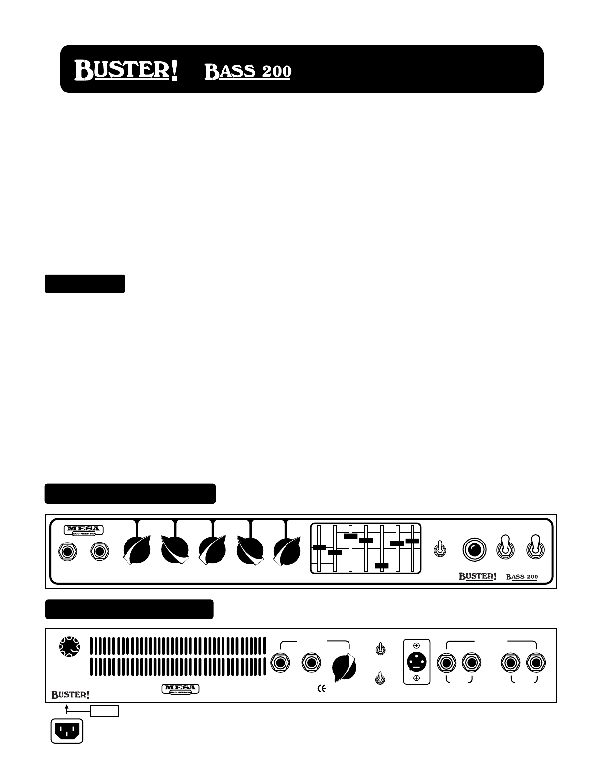
Overview:
Your new BUSTER BASS 200 incorporates a single channel, all-tube pre-amp with the standard array of
interactive rotary controls. It also provides a 7 Band Graphic Equalizer that may be used to further shape the sound and it can be used
in conjunction with the rotary tone controls. The GRAPHIC EQ may be activated manually, or via a mini toggle switch located on the
Front Panel. It may also be activated with the EQ Footswitch included with BUSTER.
Input sensitivity, headroom and overall character of the channel is determined with the VOLUME Control found at the far left of the
Front Panel. Output volume and overall listening level is controlled with the MASTER Control to the right of the tone controls. As you
might have guessed, the pre-amp VOLUME may be run high and the power section (MASTER) set low to produce some interesting
pushed or overdriven sounds.
BUSTERS’ healthy power section is fueled by six 6L6GC power pentode tubes and is rated at a very conservative 200 watts RMS.
These six 6L6s’ are fed by a circuit maximizing a single 12AX7 driver tube that contributes greatly to its responsive, dynamic character. Upon experiencing the attack, punch and power of the sound for the first time, most people are amazed to learn that BUSTER
isn’t rated as far more powerful than 200 watts ! While we are pleased - we have always preferred to stick to true power ratings and
let the all-tube tone do the talking.
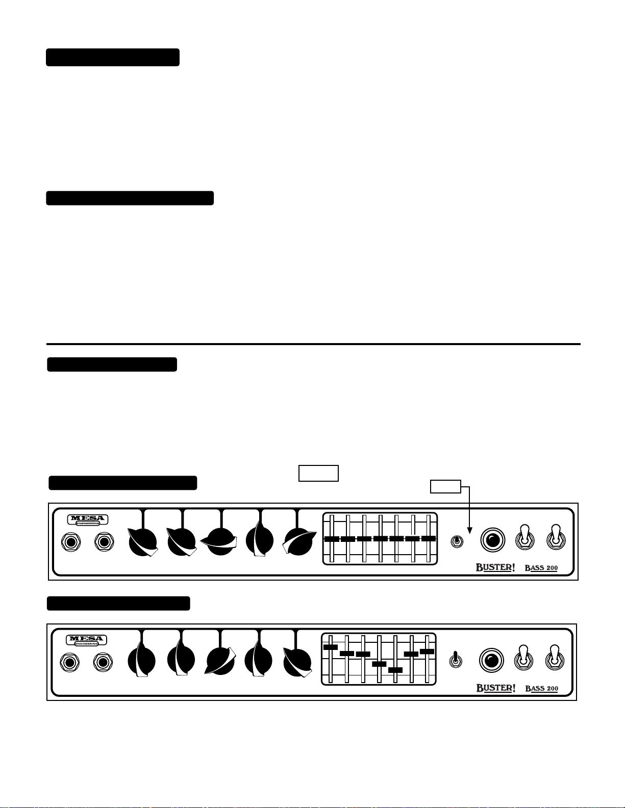
FRONT VIEW: BUSTER
INPUT
EQ FTSW
VOLUME
BASS 200
TREBLE
MID
BASS
MASTER
40Hz 100
250 625 1560 3900 6600
EQ. IN
EQ. OUT
EQ. FTSW.
ON ON
STANDBY
POWER
REAR VIEW: BUSTER
FUSE
6.25A. S B
117 V.
60 Hz.
6.25A
WARNING:
To reduce risk of fire or elec-
trical shock,replace fuse with the same
type and rating only. Do not expose
this unit to rain or moisture.
NOTE: Euro style power cord receptacle is under this edge of chassis.
BASS 200
CAUTION:
To reduce risk of fire electric shock, do not remove cover. No userserviceable parts inside. Refer
servicing to qualified personnel..
EFFECTS
SEND RETURN
PAGE 1
10% 100%
FX
BLEND
SPEAKER MUTE
SPKR ON
LIFT
GROUND
PIN 1
DIRECT OUT
SPEAKERS
4 OHM
HANDBUILT BY MESA/BOOGIE LTD. IN PETALUMA, CA
8 OHM
Page 6
OVERVIEW: (Continued)
BUSTER is equipped with a buffered parallel Effects Loop with an EFFECTS BLEND Control
which is located on the Rear Panel for interfacing outboard signal processors. For direct interfacing to a recording console or live
mixing board, we have provided a balanced XLR DIRECT OUTPUT which is fed by the VOLUME Control. There is also a SPEAKER
MUTE switch for those times when you want to go direct and don’t want to hear the speakers live.
The innovative Wedge 2 x 10 design makes BUSTER a portable combo alternative to the giant rigs of the past. The custom designed
Basis 10" speakers are capable of surprising volumes even at the lowest frequencies making BUSTER the rig of the future for the
bassist on the move.
TRANSPORTING BUSTER COMBO:
WARNING ! READ AND REMEMBER !
When towing BUSTER by the Retractable handle...Always make sure the Retractable handle is locked in place !
*Always make turns slowly thus keeping both wheels on the ground !
*Always keep your wrist in the center of the handle and support handle with both hands when making a turn !
*Never pull BUSTER off curbs - Stop, Turn Around At The Curb and lower from the curb with both hands !
INSTANT GRATIFICATION:
Before reviewing the controls and understanding their role in shaping your sound, let’s take a moment to hear what BUSTER can do
with these quick demos.
Don’t forget to to remove the protective plastic webbing from the tubes before connecting the A.C. power cord! See page 6
for important information about power-up.
NOTE: The EQ mini-toggle switch
DEMO NUMBER 1: Fingerstyle
should be in the middle position OUT
ON ON
EQ. IN
EQ. OUT
INPUT
EQ FTSW
VOLUME
TREBLE
MID
BASS
MASTER
40Hz 100
250 625 1560 3900 6600
EQ. FTSW.
STANDBY
POWER
DEMO NUMBER 1: Thumbing
ON ON
STANDBY
POWER
INPUT
EQ FTSW
VOLUME
TREBLE
MID
BASS
MASTER
40Hz 100
EQ. IN
EQ. OUT
EQ. FTSW.
250 625 1560 3900 6600
Now that you have a better idea of what BUSTER can do and have had a first hand look at the features on board, understanding the
controls and how they interact to achieve the sounds you are are looking for is the next step, so let’s get to it!
PAGE 2
Page 7
FRONT PANEL:
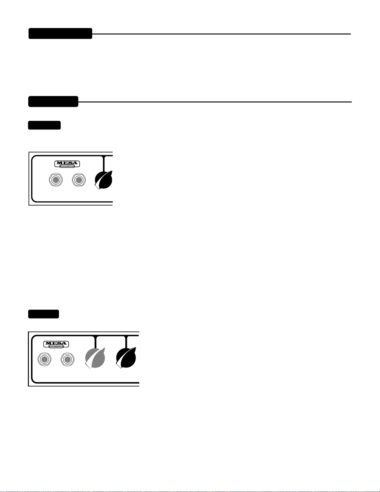
First familiarize yourself with the layout of the Front Panel and locate the EQ FTSW jack. This jack, when connected to your footswitch
will allow you to engage the 7 Band Graphic EQ remotely. If there isn’t a footswitch available, the mini-toggle on the right side of the
EQ (Front Panel) will allow you to engage the EQ manually (EQ IN). Be sure that this mini-toggle is in the down (EQ FTSW) position
when the footswitch is connected to it’s designated input jack.
CONTROLS:
VOLUME:
This control determines the overall character of the input sensitivity. The lower regions of the control (below 12:00)
lend greater headroom and provide a scooped, brighter personality. The upper harmonics come through more prominently in this area
of the control making the top end sound more transparent and sweet. This region is especially useful for funkier stuff when thumbing
is the choice. It keeps the rubber- band feel intact in the lows and mids while voicing the snap
just high enough to avoid harshness, or the dreaded “gak” when the G string is plucked.
As the VOLUME is increased past 12:00 a richer, more “well-rounded” voice becomes dominant and headroom starts to diminish in increments until eventually, a tube overdrive sound
appears as the 12AX7 input tube is driven into saturation. The region between 12:00 and 2:30
INPUT
EQ FTSW
VOLUME
is where the classic, warm tube sound resides and within this narrow band you will discover a
world of tone. Tiny increments here produce subtle, but important differences in the attack
characteristic which in turn, feel like changes in the time domain. By experimenting with the amount of gain, you can actually voice the
amp to feel as if it bounces just ahead of the groove - or lays back a little deeper to produce a more Fatback feel. The difference in
attack and sustain produces striking results as to how the bassist - and in fact the whole band - perceives things in the time domain.
At the top of the VOLUME Control there is ample gain available to push the envelope, and up here, you will find the harder side of
BUSTER. This type of sound is great for alternative and rock styles where some overdrive is needed, but defined attack cannot be
compromised as it’s still important to establish the groove. Some Bassists that would otherwise never play “distorted bass” may find
a little of this tube overdrive valuable in the studio for solo passages or just to double track a part that needs a little attitude.
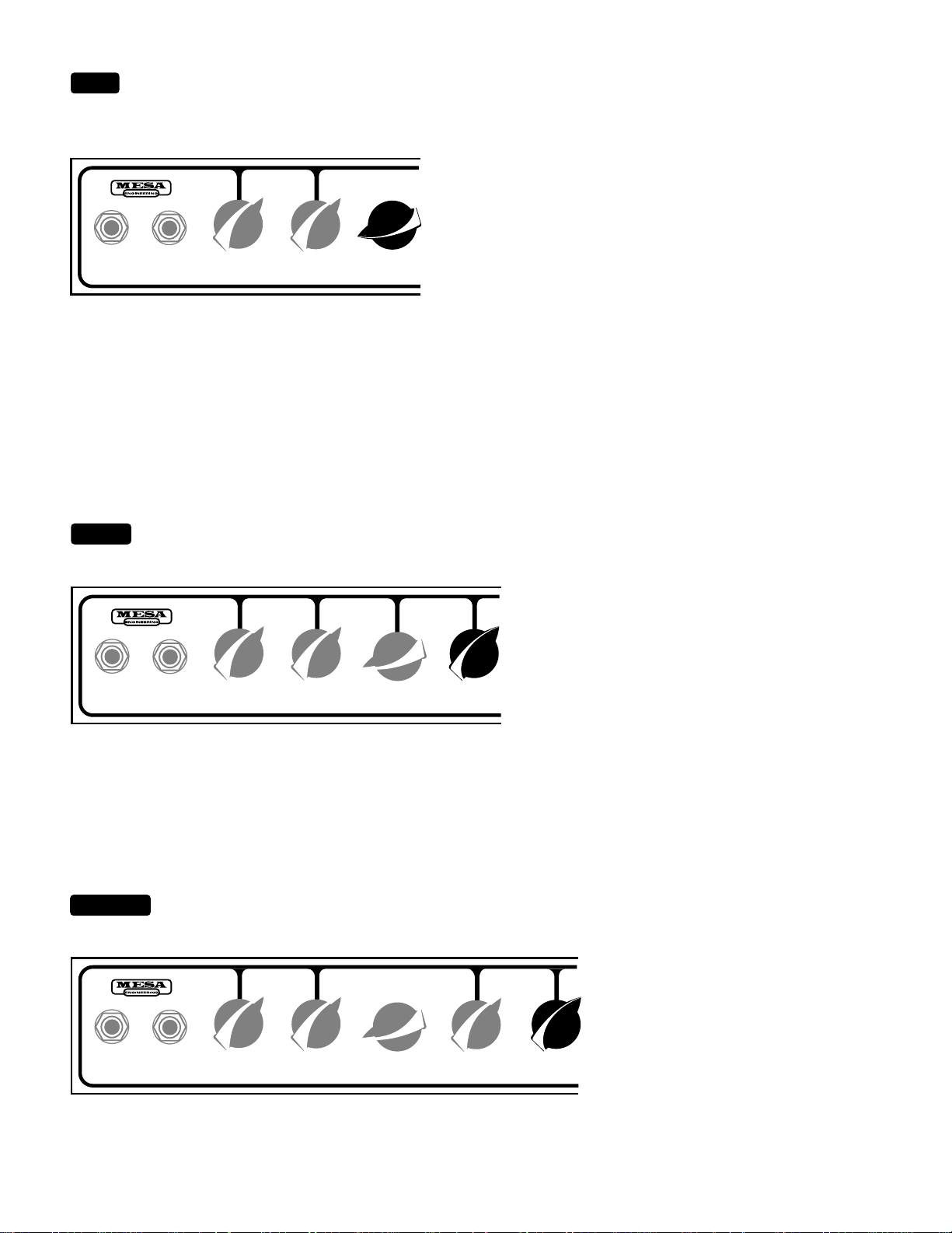
TREBLE:
As with most tube amplifiers, the TREBLE Control is the most powerful of the three rotary tone controls. Its setting
determines the mix of the MIDDLE and BASS and at high settings of the TREBLE Control, the MID and BASS have a much reduced
effect on the signal. This interaction is normal and therefore, we suggest using the
TREBLE somewhere in the middle regions 10:00 - 2:30.
If you require additional emphasis on the top end harmonics, the 7 Band Graphic
Equalizer is the perfect tool. Simply dial in a curve that accentuates the highs and
possibly even scoops the mids to bring out a brighter voice while leaving the lows
INPUT
EQ FTSW
VOLUME
TREBLE
untouched.
The equalizers’ seven “Q” points are discreet and the separate frequencies do not interact in the same way as those found in the
TREBLE Control, and yet the bands are spread wide enough to allow musical shaping of the sound. This wider-band style of equalizer
found aboard BUSTER is infinitely more friendly to use than a traditional 31 (or more) Band EQ that you might use for sound
reinforcement or studio applications. These equalizers are great for notching problem areas in a troublesome venue or a complex
studio mix, but can cast the player with limited experience on these powerful tools into a frustrating no-tone-zone real fast.
PAGE 3
Page 8
MID:
This control blends the lower midrange roundness and upper mid attack frequencies in and out of the mix. Like the TREBLE
Control, it is more powerful as the pot is increased toward the top of its range. At the top of the control it becomes the dominant tone
control and the effectiveness of the TREBLE and BASS will be greatly diminished. The MID differs slightly from the other two tone
controls in that when the control is all the way down and the mids are
turned off completely - there are some very usable sounds. In fact, this
setting would actually be preferred in many instances for thumbing and
funk style playing.
This scooping of the midrange frequencies lends a more elastic, rub-
INPUT
EQ FTSW
VOLUME
TREBLE
MID
ber-band-like feel to the strings that makes many players feel more
comfortable and expressive. Since the rotary tone controls offer a more
blend-conscious approach to EQ’ing, the scooping of the mids here
also makes the top end seem sweeter and allows the super-high frequencies to shine through a little more clearly. This makes for
some exciting, yet never harsh, snap when plucking the G string during thumbing passages. Because of the awesome presence and
punch BUSTERS’ all-tube power section delivers, many players find they don’t need very much of this midrange frequency - so don’t
be surprised if you find yourself using what you might consider to be a lower than normal setting on this control.
BASS:
Way huge found here ! This final rotary control dials in and out the rich, warm bottom end tube amplifiers are famous
for...and in BUSTERS’ case there is no shortage of this crucial ingredient. All regions of this control may be used without penalty with
the possible exception of things getting a bit tubby if you
are using the VOLUME Control maxed for an overdriven
sound. In this scheme, it may be better to attain empha-
BASS:
sized low end from the three bottom sliders of the EQ.
In general, the low end found here in the rotary controls,
INPUT
EQ FTSW
VOLUME
TREBLE
MID
BASS
as opposed to the type found in the lower region of the
Graphic EQ, tends to be of a breathier nature, rounding
and smoothing out the sound and filling in the gaps when
more focused, super-tight bottom end is required for a specific part it may be wise to set the rotary BASS Control at 12:00 or below
and dial in some of the desired frequency from the lower bands of the Graphic.
MASTER:
This is the overall Output Level Control for BUSTER and it is responsible for signal level fed to the power stage. It
may be used to increase and decrease the listening level once the desired tone and color have been shaped by using the front end
VOLUME Control.
INPUT
EQ FTSW
VOLUME
TREBLE
MID
BASS
PAGE 4
MASTER
As mentioned in the VOLUME section earlier in this manual, the gain may be set as to
achieve an overdriven sound and then volume level reduced with the MASTER Control to a desired listening level.
Page 9

GRAPHIC EQ:
This wide band, seven point graphic equalizer is the alternate shaping tool for BUSTERS’ dynamic pre-amp and
by adding it to the already powerful rotary tone controls, virtually any sound you desire can be dialed up. The equalizer may be
assigned to affect the signal in two different ways. The three position toggle located just to the right of the sliders gives you these three
choices; “IN” puts the EQ in the signal path all the time - “OUT” bypasses the EQ altogether
and “EQ FTSW” allows remote control of the EQ at will when the EQ footswitch is connected to
the “Footswitch” jack located on the left side of the Front Panel.
The EQ may be dialed in to produce some amazing sounds without necessarily knowing the
frequency you are searching for or understanding the relationship of the seven “Q” points. This
40Hz 100
250 625 1560 3900 6600
is largely due to its’ wide band nature. If you do want to use it for more frequency specific
shaping, it may be helpful to think of it as an enhanced set of tone controls that offer two slider
pots per region and a single “harmonic enhancer” slider pot up top. The “40” Hz and “100” Hz
sliders control the low end with “40” blending in sub-low harmonics and breath while the “100” defines the clarity and punch of the low
end. The “40” Hz can be helpful in getting the low “B” on a 5 string instrument to remain present in a mix. These frequencies tend to
require more attention due to their sub-low nature and the added power of the EQ is extremely apparent here.
The “250” Hz and “625” Hz sliders define both lower and high midrange frequencies and are very important to the feel of the strings
on your instrument and the attack characteristic of the sound. The “250” controls the low mids bringing in a rich, round quality that is
desirable for blues, jazz, rock and old style R&B. The “625” is a very sensitive band and it is most often used to scoop the higher mids
for thumbing style playing - rather than boosting this volatile region. When experimenting with this band you will probably find that too
much of this frequency adds a nasal quality that can become harsh if you are not careful. However, some players like to reinforce their
single note solo work with a little bit of this band as it helps bring the sound forward in a mix while adding punch to the higher notes.
The treble region of the sound is split between the “1560” Hz and the “3900” Hz bands. The “1560” blends in the aggressive low treble
attack and allows you to determine the amount of cut the sound has in relationship to other instruments. The “3900” takes responsibility for the region often referred to to as “sparkle” and “shimmer”, giving you a finer resolution of the top end than is possible with the
rotary TREBLE Control. This brings us to the “6600” Hz, the top band of the EQ. This band controls the super high frequencies and
upper harmonics. This region has a lot to do with how open and transparent the sound will be, and even though it is far above the
fundamental top note on your instrument it is quite important. For Roots and Rock styles you will probably want to keep this band fairly
low in the mix to produce a rounder, richer tone. Conversely, for Funk and R&B styles where thumbing is used a lot, the “6600”
provides the snap at just the right frequency and will probably be desirable set higher in the mix. The “6600” can also come in handy
for giving new life to dead strings that have lost their luster. By blending in a small amount of this frequency you can squeak another
session or two out of old, flat sounding strings.
Now that you have a better understanding of all the bands in the EQ and how they relate to one another, we encourage you to spend
some time experimenting with this powerful tonal resource, keeping in mind that the only limitation is your imagination and that there
are no rules. Explore and enjoy. With a better understanding of how the VOLUME and Tone Controls interact and how you can further
shape the sound with the Graphic EQ, you now have the Front Panel fairly well mastered. Before we move on to the Rear Panel, lets
review the toggle switches and the important use of the POWER ON and STANDBY switches.
TOGGLE SWITCHES
EQ IN / OUT:
EQ. IN
This mini toggle simply allows you to engage the EQ manually via the flip of a switch when the EQ Footswitch is
not available or you are without one.
ON ON
EQ. OUT
EQ. FTSW.
STANDBY
POWER
PAGE 5
Page 10

STANDBY:
Perfect for set breaks... this toggle switch also serves an even more important purpose. In the STANDBY position the
tubes are at idle so that during power up they may warm up before being put to use.
Before POWER is switched on make sure the STANDBY switch is in the Standby
position. Wait at least 30 seconds and then flip the STANDBY to the “ON” position.
This prevents tube problems and increases their toneful life substantially.
NOTE: Remember...remove the protective plastic coating from the tubes before you
connect BUSTER to an A.C. outlet.
EQ. IN
EQ. OUT
EQ. FTSW.
POWER:
This switch delivers the A.C. power to your new BUSTER BASS 200. Make sure the unit is grounded (all three
ON ON
STANDBY
POWER
terminals of the A.C. cord must be connected whenever possible to avoid injury to the user as well as to the unit) and that the proper
voltage is present. Follow the cold start procedure described in the above section ON /
STANDBY when powering up the unit.
EQ. IN
EQ. OUT
EQ. FTSW.
ON ON
STANDBY
POWER
REST AREA
PAGE 6
Page 11

FUSE
REAR PANEL:
6.25A. S B
117 V.
60 Hz.
6.25A
EFFECTS
WARNING:
To reduce risk of fire or elec-
trical shock,replace fuse with the same
type and rating only. Do not expose
this unit to rain or moisture.
CAUTION:
To reduce risk of fire electric shock, do not remove cover. No userserviceable parts inside. Refer
servicing to qualified personnel..
SEND RETURN
NOTE: Euro style power cord receptacle is under this edge of chassis.
10% 100%
FX
BLEND
SPEAKER MUTE
SPKR ON
LIFT
GROUND
PIN 1
DIRECT OUT
SPEAKERS
4 OHM
HANDBUILT BY MESA/BOOGIE LTD. IN PETALUMA, CA
8 OHM
FUSE:
This is the A.C.’s (Alternating Current) main fuse and provides protection from outside A .C. fluctuations as well as possible
power tube failure damage. Should the fuse blow, replace it with the same rating in a Slo-Blo type package. The domestic U.S. version
requires a 6.25 amp Slo-Blo fuse. A power tube short or failure is often the cause of a blown fuse...Follow the cold start procedure
mentioned in the ON / STANDBY switch section and watch the power tubes as you turn the STANDBY to the ON
position. If a power tube is going bad or is arcing you will see it! Turn the STANDBY switch to Standby immediately and
FUSE
6.25A. S B
117 V.
60 Hz.
6.25A
USTER!
B
A.C. RECEPTACLE:
replace the faulty power tube and the fuse if necessary. If you see nothing abnormal as you lift the STANDBY, it is
possible that a power tube shorted temporarily and blew the fuse. If this is the case it may work again normally. To be
extra safe, you might want to replace just the adjacent tube or all power tubes in the “shotgun” troubleshooting tradition
and save the replaced set as spares. Spare fuses and tubes are a must for the fabled cord bag and could be worth their
weight in gold someday. See pages 9 &10 for more information on tube replacement and maintenance.
The total power consumption for the BUSTER BASS 200 is 6.25 Amps. Thus, a 15 Amp circuit (which
is what most house circuitry is wired with) is adequate. Make sure the Euro style A.C. power cord is firmly seated in the power
receptacle before powering up the unit. This style of power cord will make tear-downs and cable routing a lot easier and save you time
as well. If you should ever need a replacement, just call and we’ll be happy to send you another one for a nominal charge.
FUSE
6.25A. S B
117 V.
60 Hz.
6.25A
USTER!
B
NOTE:
of the chassis on the left side.
EFFECTS LOOP: SEND & RETURN
cessing. This loop consists of a 1/4" SEND jack and a 1/4" RETURN that feeds an FX BLEND control which mixes in the wet signal to
CAUTION: To reduce risk of fire elec-
tric shock, do not remove cover. No userserviceable parts inside. Refer
servicing to qualified personnel..
Power cord is located just under the edge
BUSTER incorporates a Parallel EFFECTS Loop for interfacing outboard signal pro-
the unprocessed dry signal. Connect the SEND jack to the Input of your processor
EFFECTS
using shielded cable of good quality. Connect the RETURN jack to the Output of your
processor with the same quality cable. It may benefit your sound to use the shortest
lengths of cable possible to avoid any roll-off of the top end caused by unwanted cable
SEND
RETURN
10% 100%
FX
BLEND
capacitance.
PAGE 7
Page 12

EFFECTS LOOP: SEND & RETURN (Continued)
Use the FX BLEND control to blend in the desired amount of the effect you
wish to use from your processor. The FX BLEND let’s you sweep between approximately 10% of the wet signal and 100% of the wet
signal mixed with the dry signal. The best results are usually found with a parallel loop of this kind by setting your effect processors’
output mix control to full wet or effect only (many processors have a separate jack that is only the wet signal or only the dry signal...use
the wet jack in this case.) Then slowly bring up the FX BLEND on BUSTER to the desired blend of effect. You will most likely find that
you don’t need a very high setting of the FX BLEND to get plenty of effect.
This scheme works very well because when the FX BLEND is low, you are listening mostly to the rich all tube tone you chose
BUSTER for - and not to the unfriendly gang of op-amps that many processors use for impedance matching and gain in their output
section. Basically, the less of the loops’ wet signal you dial in...the more pure your tone will be. This is the advantage of having an
effects loop in parallel with the signal as opposed to one in series with the signal; where the entire tone of your amplifier passes
through the processor.
NOTE: You will notice that there is still some effect ( wet signal ) detectable at the low end of the FX BLEND control ( 10% ). This was
necessary to avoid oscillations that might otherwise occur should a processor with a very small impedance difference between its
Input and Output be interfaced to BUSTERS’ loop.
It is also a good practice to keep the processors Input and Output Level Controls ( preferably both ) as close to “unity gain” as possible.
Oscillation between the SEND and RETURN stages in BUSTER could occur which would produce a loud howling sound if this
practice is ignored.
SPEAKER MUTE:
This switch is designed to be used in conjunction with the DIRECT OUTPUT to mute the speaker when going
direct to a console for recording situations. It defeats the signal to the driver stage, thereby protecting the output transformer from
damage when there is no load connected to the speaker outputs. Even with this safeguard it is still a wise idea to keep the speakers,
or a load of some kind ( such as a load resistor ) connected at all times to avoid acciden-
EFFECTS
SEND RETURN
10% 100%
FX
BLEND
PIN 1 LIFT / GROUND:
SPEAKER MUTE
SPKR ON
LIFT
GROUND
DIRECT OUT
PIN 1
This switch is also part of BUSTERS’ balanced DIRECT OUT circuit. It lifts ( floats ) the ground for pin
tal damage to your amplifiers’ output transformer. If after transporting BUSTER you
find that you have no sound upon power-up, check this switch...it may have been bumped
in transit and could be mistakingly set to the MUTE position.
1 of the male 3 pin XLR output. The upper position of the two position mini toggle lifts the ground for PIN 1 - the lower position
connects pin 1 to chassis ground. When you are interfacing to a console for either live or recording, it may be necessary to lift this
chassis ground to avoid unwanted buzz or hum.
FX
BLEND
SPEAKER MUTE
SPKR ON
LIFT
GROUND
PIN 1
DIRECT OUT
EFFECTS
SEND RETURN
10% 100%
PAGE 8
Page 13

DIRECT OUT:
This male 3 pin XLR is the balanced DIRECT OUT for BUSTER. As mentioned in the last two sections above,
there is a SPEAKER MUTE function along with a PIN 1 Lift for the chassis ground. The DIRECT OUT is fed by the entire pre-amp
signal, the 7 Band Graphic EQ and finally the Effects Loop. It is not fed by the power section. The VOLUME ( far left ) Control is the
Level Control for the DIRECT OUT. The best signal to noise ratio is found by running this control at 12:00 or
SPEAKER MUTE
above and setting the consoles’ channel input trim attenuator at a fairly low level. It may also be necessary to
use the microphone pad on the consoles’ input stages to obtain adequate headroom.
SPKR ON
LIFT
GROUND
PIN 1
DIRECT OUT
If you need the extra brightness found in the lower region of the VOLUME Control, you may be forced to run
the input of the console a little hotter and subsequently - live with the associated higher amount of noise
produced by this gain scheme.
SPEAKERS:
BUSTER incorporates two sets of speaker output jacks for use with different cabinet set-ups and between them
most impedance loads can be accommodated. Two 8 ohm, and two 4 ohm outputs are provided for matching different or additional
cabinets. The 8 ohm outputs should be used with the BUSTER combo as the two custom designed Electro-Voice Basis 16 ohm - 10"
speakers are wired in parallel, producing a total impedance load of 8 ohms. If you have chosen
the Head version of BUSTER, you will likely find yourself using different impedance loads from
SPEAKERS
time to time. Here are some of the more common scenarios for a proper impedance match;
* 1 x 4 ohm cab - use 4 ohm output
* 2 x 8 ohm cabs - use the two 4 ohm outputs
4 OHM
HAND BUILT BY MESA/BOOGIE LTD. IN PETALUMA, CALIF
8 OHM
* 2 x 16 ohm cabs - use the two 8 ohm outputs
* 1 x 16 ohm cab + 1 x 8 ohm cab - use 16 ohm cab
in 8 ohm output and 8 ohm cab in 4 ohm output
Although it is possible to use 2 x 4 ohm cabinets with BUSTER by connecting each of them to the 4 ohm outputs, power will be
reduced and the bold authority present with the proper impedance match will be compromised. This mismatch will also put excessive
loading on the transformer which will produce additional heat, thus tube life may be shortened. If you must use the BUSTER with two
4 ohm cabinets, it would be wise to combine them in series in an external box or connector and then connect that combined 8 ohm
load to one of the 8 ohm outputs on BUSTER.
PAGE 9
Page 14

Factory Settings
SAMPLE 1
EQ FTSW
INPUT
SAMPLE 2
EQ FTSW
INPUT
Tight, Punchy Fingerstyle
VOLUME
TREBLE
MID
Round, Warm R & B
VOLUME
TREBLE
MID
BASS
BASS
MASTER
MASTER
40Hz 100
40Hz 100
250 625 1560 3900 6600
250 625 1560 3900 6600
EQ. OUT
EQ. IN
EQ. OUT
EQ. FTSW.
EQ. OUT
EQ. IN
EQ. OUT
EQ. FTSW.
ON ON
STANDBY
ON ON
STANDBY
POWER
POWER
SAMPLE 3
EQ FTSW
INPUT
SAMPLE 4
EQ FTSW
INPUT
Rock Solid
VOLUME
TREBLE
Rubber Band Funk
VOLUME
TREBLE
MID
MID
BASS
BASS
MASTER
MASTER
40Hz 100
40Hz 100
250 625 1560 3900 6600
250 625 1560 3900 6600
EQ. IN or OUT
EQ. IN
EQ. OUT
EQ. FTSW.
EQ. IN
EQ. IN
EQ. OUT
EQ. FTSW.
ON ON
STANDBY
ON ON
STANDBY
POWER
POWER
PAGE 10
Page 15

SAMPLE 1
Personal Settings
EQ FTSW
INPUT
SAMPLE 2
EQ FTSW
INPUT
VOLUME
VOLUME
TREBLE
TREBLE
MID
MID
BASS
BASS
MASTER
MASTER
40Hz 100
40Hz 100
250 625 1560 3900 6600
250 625 1560 3900 6600
EQ. IN
EQ. OUT
EQ. FTSW.
EQ. IN
EQ. OUT
EQ. FTSW.
ON ON
STANDBY
ON ON
STANDBY
POWER
POWER
SAMPLE 3
EQ FTSW
INPUT
SAMPLE 4
EQ FTSW
INPUT
VOLUME
VOLUME
TREBLE
TREBLE
MID
MID
BASS
BASS
MASTER
MASTER
PAGE 11
40Hz 100
40Hz 100
250 625 1560 3900 6600
250 625 1560 3900 6600
EQ. IN
EQ. OUT
EQ. FTSW.
EQ. IN
EQ. OUT
EQ. FTSW.
ON ON
STANDBY
ON ON
STANDBY
POWER
POWER
Page 16

NOTE: BEFORE CHANGING TUBES TURN POWER SWITCH TO OFF.
ALL 6L6GC
TUBE TASK CHART
12AX7
V 3
V 2
B A
B A
V 1
B A
12AX7
Tubes
V2 A = 3rd Stage
V2 B = FX Return Stage
V3 A and B = Phase Splitter
V1 A =1st Input/Gain Stage
V1 B = 2nd Stage
Description of Tube Functions
6L6GC
Power
PAGE 12
Page 17

TUBE NOISE & MICROPHONICS
You may occasionally experience some form of tube noise or microphonics. Certainly no
cause for alarm, this quirky behavior comes with the territory and the Tone. Much like changing a light bulb, you don’t need a
technician to cure these types of minor user serviceable annoyances and in fact, you’ll be amazed at how easy it is to cure tube
problems...by simply swapping out a pre-amp or power tube!
First may we suggest that you set the amplifier up on something so that you can get to the tubes comfortably without having to bend
down. It also helps to have adequate lighting as you will need to see the tube sockets clearly to swap tubes. Use caution and common
sense when touching the tubes after the amplifier has been on as they may be extremely hot! If they are hot and you don’t want to wait
for them to cool off, try grasping them with a rag and also note that the glass down around the bulbous silvery tip is considerably less
hot which makes it easier to handle. Gently rock the tube back and forth as you pull it away from its socket.
DIAGNOSING POWER TUBE FAILURES:
There are two main types of tube faults: shorts and noise. Both large and small tubes may fall prey to either of these problems but
diagnosis and remedy is usually simple.
If a fuse blows, the problem is most likely a shorted power tube and shorts can either be mild or severe. In a mildly shorted tube the
electron flow has overcome the control grid and excess current flows to the plate. You will usually hear the amp become distorted and
begin to hum slightly. If this occurs, quickly look at the power tubes as you switch the amp to STANDBY and try to identify one as
glowing red hot. It is likely that two of a pair will be glowing since the “shorted” tube will pull down the bias for its adjacent mates, but
one tube may be glowing hotter — and that one is the culprit. The other two are often fine — unless they’ve been glowing bright red
for several minutes.
Because there is no physical short inside the tube (just electrons rioting out of control) merely switching to STANDBY for a few
moments then back to ON will usually cure the problem...at least temporarily. Watch the tubes carefully now. Should the problem
recur, the intermittent tube will visibly start to over heat before the others and thus it can be identified. It should be replaced with one
from the same color batch, shown on its label. Call us and we will send one out to you.
The severe short is not nearly so benign. In the worst cases, a major arcing short occurs between the plate and the cathode with
visible lightning inside the glass and a major noise through the speaker. If this is seen to happen, IMMEDIATELY turn the amp to
STANDBY. By this time the fuse probably will have blown. Such a short is usually caused by a physical breakdown inside the tube
including contaminate coming loose or physical contact (or near contact) between the elements. Replace it and the fuse with the
proper slo-blo type and power up the amp using the power up procedure as we described earlier in this manual.
TUBE NOISE:
Often caused by contamination within in a tube, the culprit can usually be identified, and by lightly tapping on the glass, you will
probably hear the noise change. Hearing some noise through the speakers while tapping on the 12AX7’s is normal however. And the
one nearer the INPUT will always sound louder because its output is being further amplified by the second 12AX7.
The power tubes should be all but quiet when they are tapped. If crackling or hissing changes with the tapping, you have probably
found the problem. To confirm a noisy power tube, merely put the BUSTER on STANDBY, remove it from its socket and turn it back
on. It will cause no damage to run the BUSTER briefly with one power tube missing. You may notice a slight background hum,
however, as the push-pull becomes unbalanced. Whenever you are trying to diagnose a suspect tube, keep your other hand on the
POWER and STANDBY switches ready to shut them off instantly in the unlikely case you provoke a major short. If you think you’ve
located a problem tube but aren’t sure, we recommend substituting the suspect with a new one just to be sure of your diagnoses.You
will be doing yourself and us a big favor by just following the simple guidelines previously mentioned regarding tube replacement.
You’ll probably be successful with much less effort than is required to disconnect everything and haul the unit to a technician who will
basically perform the same simple tests. If the tubes are still within their six-month warranty period, we will happily send you a
replacement. Just note the color designation on the tube label so that we can send you the appropriate match.
PAGE 13
Page 18

DIAGNOSING PRE-AMP TUBE PROBLEMS:
Because your amplifier is an all tube design, it is quite possible that you will at
some point experience minor pre-amp tube noise. Rest assured - this is no cause for alarm and you can take care of the problem
yourself in a matter of minutes by simply swapping tubes.
Let us begin by saying; It is a “very good” idea to keep at least a couple of spare pre-amp tubes on hand at all times to insure
uninterrupted performance. These minor pre-amp tube problems can take many forms but can generally be described in two categories: Noise and Microphonics. Noise can be in the form of crackling, sputtering, white noise/hiss and/or hum. Microphonic problems
usually appear in the form of a ringing or high pitched squealing that gets worse as the gain or volume is increased thus are more
noticeable in the higher gain “HI” modes. Microphonic problems are easily identified because the problem is still present even with the
instruments’ volume off or unplugged altogether - unlike pick-up feedback which ceases as the instrument is turned down. Microphonic noise is caused by mechanical vibration and shock: think of banging a microphone around and you’ll understand where the
word came from.
The best way to approach a pre-amp tube problem is to see if it occurs only in one specific mode or channel. Then refer to the TUBE
TASK CHART on page 12 and it should lead you to the tube needing replacement. Then all that remains is to swap the suspect tube
for a known good performer.
If you cannot narrow down the trouble to a specific mode or channel, the problem may be the small tube that drives the power tubes
which is operational in all modes and channels. Though rare, a problem with the driver tube would show up in all aspects of performance - so if you can’t narrow the problem down to being mode or channel specific, you may want to try replacing the driver tube.
Driver problems generally show themselves in the form of crackling or hum in all modes of performance and/or weak overall output
from the amplifier. Occasionally an anemic driver tube will cause the amplifier to sound flat and lifeless, but this is somewhat uncommon, as worn power tubes are a more likely suspect for this type of problem.
Sometimes making the diagnosis is more trouble than it’s worth and it’s faster and easier to merely replace the small pre-amp tubes
ONE AT A TIME with a replacement known to be good. But MAKE SURE you keep returning the tubes to their original socket until you
hit the one that cures the problem. You’ll notice that tubes located nearer to the INPUT jack always sound noisier...but this is because
they are at the start of the chain and their noise gets amplified over and over by the tubes that follow. The tube that goes into this
“input socket” (usually labeled V1) needs to be the least noisy of the bunch. The tube that goes at the end of the preamp chain - just
ahead of the power tubes - can be quite noisy without causing any problem at all. The tubes in your amp have already been located
in the most appropriate sockets and this is why you should NEVER pull them all out at once and ALWAYS swap them one at a time.
ALWAYS return a perfectly good tube to its original socket. Also it’s a good idea to put the amp on STANDBY when swapping tubes to
reduce the heat build up in the tubes themselves and to prevent explosive noises (which can still occur even if you are pulling the
tubes away from their sockets gently) from coming through the speaker.
Remember, take your time, be patient and chances are real good that you can fix your amp yourself by finding and replacing the bad
tube. It kills us to see someone who has shipped their amp back to us...and all it needed was a simple tube replacement! If you must
send back your amp, unplug the power cord, speaker and reverb cables then remove the chassis from the cabinet by unscrewing the
four mounting bolts on top. The chassis then slides back like a drawer and comes out. Remove the big power tubes and mark them
according to their location from left to right 1, 2 etc. They need to be wrapped separately with plenty of wadded up newspaper around
them and put in a smaller box within the larger carton. To wrap the chassis, use plenty of tightly wadded up newspaper so there is at
least six inches of “crush space” between the chassis and the cardboard box. Bubble wrap also works well, but please DON’T use
styrene peanuts - they will shift during transit and get lodged inside your electronics as well as allowing your amp to end up at the
bottom of the box unprotected and possibly damaged. Pre-amp tubes don’t normally wear out as a rule. Therefore, it is not a good
idea to change them just for the sake of changing them. If there isn’t a problem - don’t fix it. If there is no result from your substitutions,
it may be possible that you have more than one problematic tube. Though rare, this does happen and though it makes the troubleshooting process a little more intimidating, it is still possible to cure the problem yourself.
NOTE: It is normal to hear a slight metallic ringing sound when tapping on the preamp tubes. As long as the tube does not break into
oscillation or start crackling or any other form of bizzare noise, it is considered normal and functional.
PAGE 14
Page 19

BIAS ADJUSTMENT: (Part of a continuous series)
NOTE: An article written by Randall Smith that
we thought you might find interesting.
Here’s a question we often hear:
“Why doesn’t Mesa put bias adjustments
in their amplifiers?”
CATHODE
( )
GRID
SCREEN
( )
GRID
BEAMCONFINING
( )
,
.
.
.
.
.
.
.
.
.
.
.
.
.
.
.
.
.
.
.
.
.
.
.
.
.
.
.
.
.
.
.
.
.
.
.
.
.
.
.
.
.
.
.
.
ELECTRODE
PLATE
( , )
( )
Well, there’s a short answer and a long answer to this question.
Structure of a 6L6 / 5881
Beam Power Pentode.
The short answer is that during my 12 years of repairing Fenders, one of the most frequent problems I saw was bias controls that were
either set wrong or that had wandered out of adjustment due to vibration. As any honest tech will tell you, there’s lot’s of easy money
to be made by sprinkling “holy water” on amplifiers ... uh, what I meant to say is “Your amp needed biasing.” See what I mean? What
customer is going to argue with that?
It only takes a moment and a volt meter: The Fender diagram shows how: “Adjust this trim pot for - 52 volts.” That’s it. Nothing more.
Now don’t be fooled into thinking that tubes “draw” more or less bias, they don’t. The way a bias supply is connected to a tube is akin
to a dead end road, it just trails off to nowhere without really completing a circuit. It’s a static voltage and regardless of what tube is in
the socket — or even if the tubes aren’t plugged in at all, it doesn’t change the bias voltage a bit.
So the end of the short answer is this: Since a bias supply needs to put out the right voltage and never vary, I wanted to build
amplifiers that were individually hard wired to the correct values and NEVER needed adjustment. And for 25 years, that’s how Mesa/
Boogies have been built.
Time to change tubes? Just plug our tubes into any one of our amps and you’re DONE. No tech needed. NO bills and no BS about
biasing. And most important: The bias is RIGHT because it can’t change!
Now, you want the long answer? Here’s more information on how our hard-wired bias avoids trouble. Please read on.
But first, let’s make an important distinction. Our business is designing and building high performance amplifiers. And for this we need
tubes whose variance is within a narrow range. Our warehouse is full of rejects ...oh, they work — they just don’t perform within our
tolerance range. We have a very sophisticated computer - based tube testing system (nicknamed “Robotube”) that matches and
measures tubes over seven important parameters. It can even predict which tubes are likely to have a shortened lifetime — even
though they work perfectly during the test.
Because our business is building quality amps, we can afford to reject a lot of wayward tubes. The guys you hear complaining
because Boogies don’t have bias adjusters are primarily in the business of selling tubes - not amps. They don’t want to throw away 30
percent of their inventory, so they promote the idea that tubes outside our parameters can be used to “customize” amplifiers and they
criticize us because our amps can’t be adjusted to accommodate their out-of-Mesa tolerance tubes.
Now you might be thinking, “But I thought you just said that tubes don’t “draw” bias, therefore they don’t effect the bias supply and thus
it doesn’t need to be adjustable.”
And that’s right. Tubes don’t effect the bias setting, but the bias setting does effect how the tubes work. But how it effects the tubes is
difficult to measure.
When you set the bias (whether it’s by selecting the right resistors, as we do, or adjusting a trimmer — which is quicker) what you are
doing is establishing the correct amount of idle CURRENT that flows through the power tubes. But you can’t adjust the current
PAGE 15
Page 20

BIAS ADJUSTMENT: (Continued)
directly, you can only change it by adjusting the amount of bias VOLTAGE that goes onto the tubes’ control grids.
Voltage and current are NOT the same. Current is the AMOUNT of electricity, the “quantity” — and is measured in amperes. Voltage
is the degree of electric charge — like the “pressure” to use the old water analogy. Let me illustrate how different voltage and current
are:
When you scrape your feet across a carpetted floor in dry, wintery conditions, your body can become charged with 50,000 to 100,000
volts of static electricity. And when you reach for the door knob, a spark jumps and you feel it! The voltage is super high but the
current (measured in micro-amps) is tiny - otherwise you would die from electrocution.
Contrast this with your car battery, which puts out a mere 12 volts. You can lay your hands right across the terminals and not feel a
thing. Yet the amount of current available can run to several hundred amperes .. enough to turn over a cold engine and get it started.
So current and voltage are two totally separate electrical parameters — though when you multiply them together, you get POWER,
which is measured in watts.
When you set the bias of an amplifier, you are adjusting the static VOLTAGE at the control grid of the tube in order to produce a
desired amount of idle CURRENT flowing to the tube’s plate. A small change in grid voltage, produces a large change in the amount
of current flowing — and that’s basically how a tube works. Say that again because it’s super important: A small change in voltage at
the grid causes a large change in current flowing to the plate. See, that’s the essence of amplification: A small change causing a large
change. And here it’s a small voltage change causing a large current change.
The bias conditions are what determines how much current flows through the big power tubes when you’re not playing. And what
drives your speakers is flucuations in that current flow when are ARE playing. If the amount of current increases and decreases 440
times per second, then you’ll hear an A note. If the fluctions in current flow are large and still at 440 per second, you’ll hear an A that
is LOUD!
But for purposes of biasing, it’s the amount of “plate current” flowing with no signal applied that’s important. Unfortunately current is
hard to measure because the circuit must be interuppted — as in “cut the wire” — and the meter spliced “in series” with the broken
circuit. But measuring VOLTAGE is easy. It is not necessary to interrupt the circuit because a voltage reading can be taken in
PARALLEL with the circuit intact.
Thus, as a matter of convenience, most bias settings are given in volts at the grid ... even though current through the plate is the
important factor. In fact plate current is so inconvenient (and dangerous) to measure that Fender doesn’t even state what the correct
value should be. They only give the grid voltage that will produce that current. (That’s the minus 52.) But that only happens if the
tubes being used are “in spec.”
As long as the tubes ARE “in spec”, the right bias voltage will always give the correct plate “CURRENT” — but then there’s no need
for the bias voltage to be adjustable!
If the tubes are NOT in spec, then the only proper way to re-set the bias is to cut the circuit and measure the current while adjusting
the bias ... but no manufacturer I know even STATES the desired current value! Be that as it may, when the original bias voltage is
altered far enough, it will compensate for the tube’s abnormal performance and the correct amount of idle current flow may then be
restored. Clearly this is something most repair techs should not attempt.
Some newer amps have LED indicators connected to the circuit which will turn on when the right threshold of current flow has been
reached. This is an improvement, and almost worthy if you’re willing to except resistors and lights added into your amplifier’s audio
path — which we aren’t. The other “advantage” of this system is that it allows some amp manufacturers to avoid matching their power
tubes. The thinking is that adjusting the bias to each tube separately eradicates the inherent differences between the tubes by
insuring that the same current flows through each one.
PAGE 16
Page 21

BIAS ADJUSTMENT: (Continued)
Again, this has some merit .. but it’s still not as good as using tubes that are matched in the first place because compensating for the
mis-match causes the push-pull circuit itself to become unbalanced. Two wrongs don’t really make a right.
Some of the other recommended biasing, “methods” — such as -”.. tubes running red hot, increase the bias .. sounds harsh and runs
too cool, turn it down ...” are guesswork at best. Luckily, one of the great things about tube amps is that they can usually stand some
abuse without causing any real harm ... at least not immediately.
But don’t these alterations imply that you are second-guessing the amp designer and that there’s a better set of operating conditions
that the designer missed but the tube sellers have discovered?
Now some players may like the sound of their amp altered by tubes with extreme characteristics and with the bias set to help
compensate. But often it is the mere novelty of change that they’re really responding to and when the amp goes back to the proper
original way, we’ve seen them be far happier still!
Because every part in every one of our designs has been meticulously evaluated, compared and stressed over — no matter how
seemingly insignificant it might be. And with every design we look for a “sweet spot” where all the parameters — including the bias —
come together to give the best sonic performance, consistently and reliably. Every part and voltage is important — yet no one
complains that these other parameters aren’t available for tinkering.
Consider our patented Simul-Class circuitry where there are two different bias voltages used for separate pairs of power tubes ... and
changing one voltage also changes the other. Great care goes into getting this just right and we think we’d be asking for trouble to
have it adjustable for the world to play with ... unless you like paying to have your amp messed up. Sorry, I meant to say, “Uh, ... your
amp needed biasing.”
If that doesn’t appeal to you, then merely plug a matched set of Mesa tubes into one of our amps and you’re ready for tone. Guaranteed. You’d be amazed at the number of service calls we field every day that lead to a diagnosis of out-of-tolerance, non-spec tube
problems. To think these would be prevented by including a bias adjustment is something of an insult to you and us. If you put the
wrong size tires on your car, do you think changing the pressure will make them right?
Please, don’t think this is a blanket indictment of the other guys selling tubes — it isn’t. And their tubes aren’t all bad either. It just
doesn’t make sense to pay more of your hard earned cash for tubes that were probably made in the same Russian or Chinese factory
and which have the possibility of being outside the performance window we select for your amp. And it pains us to hear the hype and
mystique built up around biasing when twenty-five years of evidence affirms our decision to make bias circuits that “never need
adjustment”. How much money and trouble that has saved Mesa/Boogie players you couldn’t estimate.
Our rigorously tested and hand selected tubes are available at your nearest Mesa/Boogie Pro Center or from us directly. Nobody
offers better price, quality or warranty than we do ... so why swerve?
Next time we’ll talk about our part in developing the great Sylvania STR 415 type 6 6 and how we’re on the verge of seeing something
fairly close reappear on the market. Remember, we still have some of these super rugged mondo-bottles available for older amps —
Boogies only please! Until then, Relax, Breathe and Nourish your soul!
Cheers!
Mesa/Boogie Ltd.
Randall Smith
Designer & President
PAGE 17
Page 22

under this corner of the Chassis
613713
B
USTER!
trical shock,replace fuse with the same
type and rating only. Do not expose
this unit to rain or moisture.
6.25A. S B
117 V.
60 Hz.
6.25A
WARNING:
To reduce risk of fire or elec-
A.C. RECEPTACLE
pt#
NOTE: The A.C. Receptacle is located
FUSE
FUSE pt# 790122
pt#
7903243
FUSE HOLDER
REAR VIEW: BUSTER BASS
POT pt#
581739
INPUT
EQ FTSW
JACKS
pt#
618102
FRONT VIEW: BUSTER BASS
pt#
618112
POT
pt#
581055
SWITCH
pt#
607101
JACK
KNOB
pt#
408010
CAUTION:
tric shock, do not remove cover. No user-
serviceable parts inside. Refer
servicing to qualified personnel..
To reduce risk of fire elec-
SEND RETURN
10% 100%
BLEND
FX
GROUND
PIN 1
SPKR ON
LIFT
EFFECTS
SPEAKER MUTE
JACK
pt#
618112
SWITCH
pt#
607101
POT pt#
VOLUME
581040
POT pt#
581737
POT pt#
581040
POT pt#
581055
TREBLE
MID
BASS
MASTER
ALL KNOBS pt#
408010
KNOBS for EQ
Sliders pt#
408535
XLR JACK
pt#
614028
ALL SPEAKER JACKS
same pt#
618112
DIRECT OUT
HAND BUILT BY MESA/BOOGIE LTD. IN PETALUMA, CALIFORNIA
4 OHM
SPEAKERS
8 OHM
PAGE 18
pt#
607203
LENS
pt#
703784
SWITCH
EQ. FTSW.
B
USTER !
STANDBY
B
ASS 200
POWER
EQ. OUT
EQ. IN
ON ON
PILOT LIGHT
pt#
703822
SWITCH
pt#
601073
SWITCH
pt#
601073
Page 23

Thank you for trusting Mesa/Boogie to be your amplifier
company. We wish you many years of toneful enjoyment
from this handbuilt all-tube instrument.
Page 24

The Spirit of Art in Technology
1317 Ross Street Petaluma, CA 94954
USA
Phone (707) 778-6565 Fax (707) 765-1503
 Loading...