

Page 1
Product Date
September 2008
MSD4 Hardware Manual
MESANOR
Page 2
RECEIVING AND HANDLING
Upon delivery of the equipment, inspect the shipping containers and contents for indications of
damages incurred in transit. If any of the items specified in the bill of lading are damaged, or the
quantity is incorrect, do not accept them until the freight or express agent makes an appropriate
notation on your freight bill or express receipt.
Claims for loss or damage in shipment must not be deducted from your invoice, nor should
payment be withheld pending adjustment of any such claims.
Store the equipment in a clean, dry area. It is advisable to leave the equipment in its shipping
container until ready fore use. Each amplifier is checked carefully before shipment. However, upon
receipt, the user should make sure that the amplifier corresponds to or is properly rated in terms of
rated voltage and current for the type of motor which is to be driven. The descriptive label affixed
to the amplifier specifies electrical ratings.
Safety and application information
According to the enclosure the Amplifiers Motors and Power supplies may have live, uninsulated or
rotating parts or hot surfaces during operation.
The inadmissible removing of the required cover, in proper application, wrong installation or
operation may lead to personal or material damages.
For further information please refer to the manual.
Only qualified personal are permitted to install or operate the equipment.
IEC 364, CENELEC HD 384, DIN VDE 0100,0105,0110 and national regulations must be
observed
According to these general safety information a qualified person is someone who is familiar with
installation, assembly, commissioning and operation of the equipment. These person must have
the appropriate qualifications.
Never plug in or unplug any connectors on the amplifier or open the amplifier when
power is applied. A time of discharge of 3 minutes must be considered
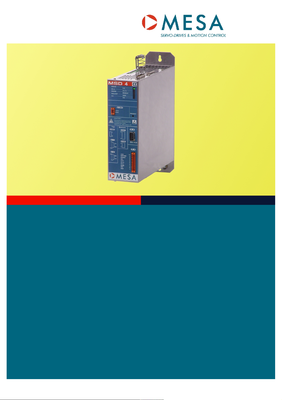
Key Features Application YOUR ADVANTAGE
Compact design
Easy installation
DC-Supply 24-48 V DC
DC-Bus coupling
Analogous input
Encoder sensor
Direct brake control with smart
switch (via Fieldbus)
Waste Disposal: According to the EC-Directive 2002/06 all drive are provided with the opposite icon. That means
that the drives cannot be put to the general rubbish or garbage.
All pick and place equipments
Single and multi axis machinery
Test equipments
Feeding systems
Wrapping machinery
Robotics
Textile machinery
Spotlight-trace control systems
Food machinery
Medical equipments
Wide range of applications
Easy matching and setup
High reliability
Firmware update via RS 232
Manual Article Code: 74.02495
MSD4 V1.02
Page 3

Table of Contents
1. Basic types of the MSD4 series – Power ranges..................................................6
1.1. Type code..................................................................................................................6
2. Common facts..........................................................................................................7
3. Technical data of the MSD4 series.........................................................................8
3.1. Technical data...........................................................................................................8
4. Functional principle and basic functions............................................................10
4.1. Block diagram..........................................................................................................10
4.1.1. State machine.........................................................................................................11
4.1.2. Operation modes.....................................................................................................11
4.1.3. Set value demand for speed, current and position..................................................13
4.1.3.1. Speed settings.........................................................................................................13
4.1.4. Control priority.........................................................................................................13
4.1.5. Error-RESET...........................................................................................................13
4.1.6. Power-On RESET...................................................................................................13
4.2. In- and Outputs........................................................................................................13
4.2.1. Digital In- and Outputs.............................................................................................13
4.2.2. Analog inputs...........................................................................................................13
4.2.3. Actual value acquisition...........................................................................................14
4.2.3.1. Encoder...................................................................................................................14
4.2.3.2. Hall feedback...........................................................................................................14
4.2.3.3. DC-Tacho................................................................................................................14
4.2.3.4. Armature voltage control with IxR compensation (opt. Var. 016 / 018)....................15
4.2.3.5. Current measurement.............................................................................................15
4.2.4. “Ready”-Output........................................................................................................16
4.2.5. Hardware-Enable.....................................................................................................16
4.2.6. Machine Switches....................................................................................................16
4.2.6.1. Stop-Input................................................................................................................16
4.2.6.2. Hardware-Limit Switch.............................................................................................17
4.2.6.3. Homing Switch .......................................................................................................17
4.3. Temperature sensors..............................................................................................17
4.3.1. Motor temperature sensor.......................................................................................17
4.4. General digital in- and outputs.................................................................................17
4.5. Control- and Diagnosis Interface.............................................................................18
4.5.1. Parameters..............................................................................................................18
4.5.2. Monitor Outputs.......................................................................................................18
5. Configuration of the Servo Amplifier...................................................................19
5.1. Basic configuration – First Steps.............................................................................19
6. Power supply.........................................................................................................20
6.1. Mains transformer...................................................................................................20
6.2. Ballast circuit...........................................................................................................20
6.3. +24 V DC Auxiliary Voltage (Electronic supply).......................................................21
6.4. Control of the motor brake.......................................................................................21
6.5. Fuses......................................................................................................................21
7. Standard settings..................................................................................................23
8. Bring-in-to-use.......................................................................................................24
MSD4 V1.0
3
Page 4

9. Description of the Connectors.............................................................................25
9.1. MSD4 Connectors...................................................................................................25
9.2. X1 Motor Sensor.....................................................................................................26
9.3. X2 Control signals...................................................................................................27
9.4. X3 RS232................................................................................................................29
9.5. X4 Digital In and Outputs........................................................................................29
9.6. X5 Digital In and Outputs (optional).........................................................................29
9.7. X6 / X7 CAN Bus.....................................................................................................31
9.8. X21 Power Supply...................................................................................................31
9.9. X22 Ballast..............................................................................................................31
9.10. X23 Motor Connector..............................................................................................31
9.11. X24 Auxiliary Voltage +24 V....................................................................................31
10. Earthing and Installation according to EMC Norms...........................................33
10.1. General Indications.................................................................................................33
10.2. General Rules.........................................................................................................33
10.3. Control Cabinet.......................................................................................................33
10.4. D-SUB Cable shielding............................................................................................34
11. Wiring.....................................................................................................................35
11.1. Cable cross sectional areas....................................................................................35
11.2. Motor cable..............................................................................................................35
11.3. Control cables.........................................................................................................35
11.4. MSD4 CAN Bus Wiring...........................................................................................35
11.4.1. General...................................................................................................................35
11.4.2. Standard Version.....................................................................................................36
11.4.3. Simplified Version....................................................................................................36
12. Connecting.............................................................................................................37
12.1. Connection to Mains Power.....................................................................................37
12.2. DC Bus Coupling.....................................................................................................37
12.3. Wiring Scheme for BLDC-Motor..............................................................................39
12.4. Wiring Scheme for DC Motor..................................................................................40
13. Mechanical Dimensions........................................................................................41
13.1. Standard Housing....................................................................................................41
13.2. Short Housing (optional)..........................................................................................42
14. Known problems and limitations.........................................................................43
15. Troubleshooting....................................................................................................43
15.1. LED Display.............................................................................................................43
15.2. Error Finding............................................................................................................44
15.3. Errors......................................................................................................................45
16. Variants and Modifications...................................................................................47
16.1. Variant 016 (MSD4 for DC Motor)...........................................................................47
16.2. Variant 018 (MSD4 for DC Motor and battery operation).........................................47
17. Additional information..........................................................................................47
17.1. Optional connector sets...........................................................................................47
18. Other products.......................................................................................................48
18.1. BME: Basic Motion Element....................................................................................48
MSD4 V1.04
Page 5

18.2. BDE: Basic Drive Element.......................................................................................48
18.3. BDE: High Current Device.......................................................................................48
19. Place for your notices:..........................................................................................49
MSD4 V1.0
5
Page 6
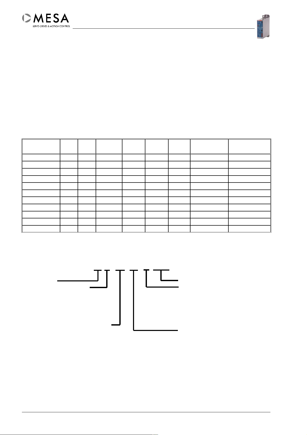
1. Basic types of the MSD4 series – Power ranges
Name of the Series Characteristics
- Mesanor
M
- Servoamplifier
S
- Digital
D
4
Fieldbus: CANopen
PC interface
Analog input
High dynamic and great bandwidth
Efficient power stage
Fast current loop
Extensive protection measurements
Limit switches and stop-input
Integrated motor brake control
Type I
[A]
max
I
Rated
[A]
U
Rated
[VDC]
U
min
[VDC]
U
max
[VDC]
Fan Inductance
L
[mH] *
min
Ballast
system
MSD4 3004 8 4 230 90 260 internal 3,9 / 2,0 internal
MSD4 3006 12 6 230 90 260 internal 2,6 / 1,3 internal
MSD4 3008 16 8 230 90 260 internal 2,0 / 1,0 internal
MSD4 3010 20 10 230 90 260 internal 1,6 / 0,8 internal
MSD4 3012 24 12 230 90 260 internal 1,3 / 0,7 internal
MSD4 3015 30 15 230 90 260 internal 1,0 / 0,5 internal
MSD4 3020 40 20 230 90 260 internal 0,8 / 0,4 internal
MSD4 5004 8 4 400 180 440 internal 6,5 / 3,3 internal
MSD4 5006 12 6 400 180 440 internal 4,4 / 2,2 internal
MSD4 5008 16 8 400 180 440 internal 3,3 / 1,6 internal
MSD4 5010 20 10 400 180 440 internal 2,6 / 1,3 internal
* Minimal motor inductance on nominal voltage: first value valid for 8 kHz PWM, second value for 16 kHz PWM
1.1. Type code
MSD4 MC 3010 E xxx
MESANOR Option / Motor type
CANopen (C) Encoder (E)
PROFIBUS (P) Resolver (R)
Indexer ( I ) DC-Tacho (T)
Analog (A) BEMF (U)
DC Bus voltage 320 V (30)
560 V (50) Nominal current in A (10)
680 V (70)
Battery devices 24..65 V (06)
36..125 V (12)
Other power ranges and options on request.
MSD4 V1.06
Page 7

2. Common facts
The devices of the MSD4 series are digital servo amplifiers for using with brushed and brushless
direct current motors (BLDC-Motors). Brushed motors with BEMF can be used with the variants
016 or 018.
Servo amplifiers named 30xx und 50xx are capable to be connected directly to mains power. They
contain all necessary components – Rectifiers, braking circuits, inrush current limitation and line
filters.
The following operation modes are available:
● Torque control: This operation mode allows a dynamic and precise torque control
between the +/- maximum torque.
● Speed control: This operation mode allows a dynamic and precise speed control between
the +/- maximum speed.
● Position control: This operation mode allows a dynamic and precise position control
between the +/- maximum position. The control device delivers only the target position in
this operation mode.
● Interpolated position control: This operation mode allows a dynamic and precise
position control. The control equipment controls the entire motor movement by giving
synchronous position set values. This operation mode is only available in the CAN version
of the MSD4 series.
● Position control via stored sequences: Servo amplifiers of the MSD4 series are able to
store 32 Positioning- and Homing sequences. The sequences can be started by their
sequence numbers.
● Speed and torque control via analog input (Stand alone): These operation modes allow
the using of the internal analog input for set value generation. There are speed and torque
set values available.
● RS 232 Mode: The PC interface is mainly for diagnosis, parametrising and test purposes.
Special features of the user interface like the “control panel”, the oscilloscope and “XYwriter” supporting the user during the bring-in-to-use and optimization procedure.
MSD4 V1.0
7
Page 8

3. Technical data of the MSD4 series
3.1. Technical data
Power supply 06xx 12xx 30xx 50xx
AC supply voltage 48 V AC * 90 V AC * 230 V AC 400 V AC
DC supply voltage / Internal bus voltage 65 V DC 125 V DC 320 V DC 560 V DC
Output voltage U
Ballast voltage 80V / - * 148 V / - * 392...400 V 658...670 V
Over voltage 86 V 160 V 420 V 700 V
Under voltage 17 V 36 V 90 V DC 180 V DC
* Rectifiers and ballast circuits are optional in battery (Variant 018) devices
A
60 V 120 V 290 V 520 V
Power stage
IGBT-Technology in mains supply devices
MOSFET-Technology in battery devices
PWM frequency 8 or 16 kHz
The power stage is protected against Over current, Winding-leakage,
Over voltage, Earth-leakage,
Over temperature
Digital current loop
Controller type PI
Set value via Field bus (16 bit)
±10 V Analog input (12 bit)
PC interface
Current limitation 1 I
Current limitation 2 I
, Maximum current
max.
, Rated current
rms
Parametrizing via Field bus or PC interface
Sample time
62,5 s
Digital speed loop
Controller type PIDFF
Set value via Field bus (16 bit)
±10 V Analog input (12 bit)
PC interface
Feedback via Encoder 250 ... 5000 ppr
Tacho, BEMF (only for DC motors)
Parametrizing via Field bus or PC interface
Sample time
250 s
Digital position control
Controller type PFF
Set value via Field bus (32 bit)
PC interface
Feedback via Encoder 250 ... 5000 ppr
Parametrizing via Field bus or PC interface
Sample time
250 s
MSD4 V1.08
Page 9

CAN - Interface
Protocol CANopen / DSP 402
Service channel SDO, Asynchronous data transfer
(Parametrizing)
Process channel PDO, Synchronous data transfer
(Process data in real time)
Baud rate max. 1 MBit/s
Parametrizing via Field bus or PC interface
Parameter storage
Common protection measurements
I²t current limitation Deactivation of the power stage / limitation of
Motor over temperature Deactivation of the power stage
Feedback error Deactivation of the power stage
EEPROM-error Deactivation of the power stage
Field bus error Deactivation of the power stage
Processor error Deactivation of the power stage
Specifications
Operation temperature 0 ... 45 °C (Derating 2%/K 45-55 °C)
Storage temperature -10 ... 60 °C
Protection class IP 20
Cooling Convection with integrated temperature
Humidity max. 65 % relative humidity
Isolation C conform with EN50178
Mounting orientation Vertical
“Ready” Signal Relais contact 50 V / 10 mA
Control of the motor brake Smart-Switch 24 V DC / 1,5 A
EEPROM (non volatile)
the output current
controlled fan
Digital In- and Outputs (+24 V DC)
Analog input
Motor types
Operation modes
Parametrizing and diagnosis via Field bus or PC interface
Set values and Feedback via Field bus
MSD4 V1.0
1 fast input
2 limit switch inputs (+/-)
1 homing switch input
1 stop input
2 programmable In- / Outputs
8 programmable In- / Outputs (optional)
2 differential analog inputs max. ±10 V
(correlated to the housing / PE)
brushless DC Motors
brushed DC Motors
Position-, Speed- and Torque control
9
Page 10
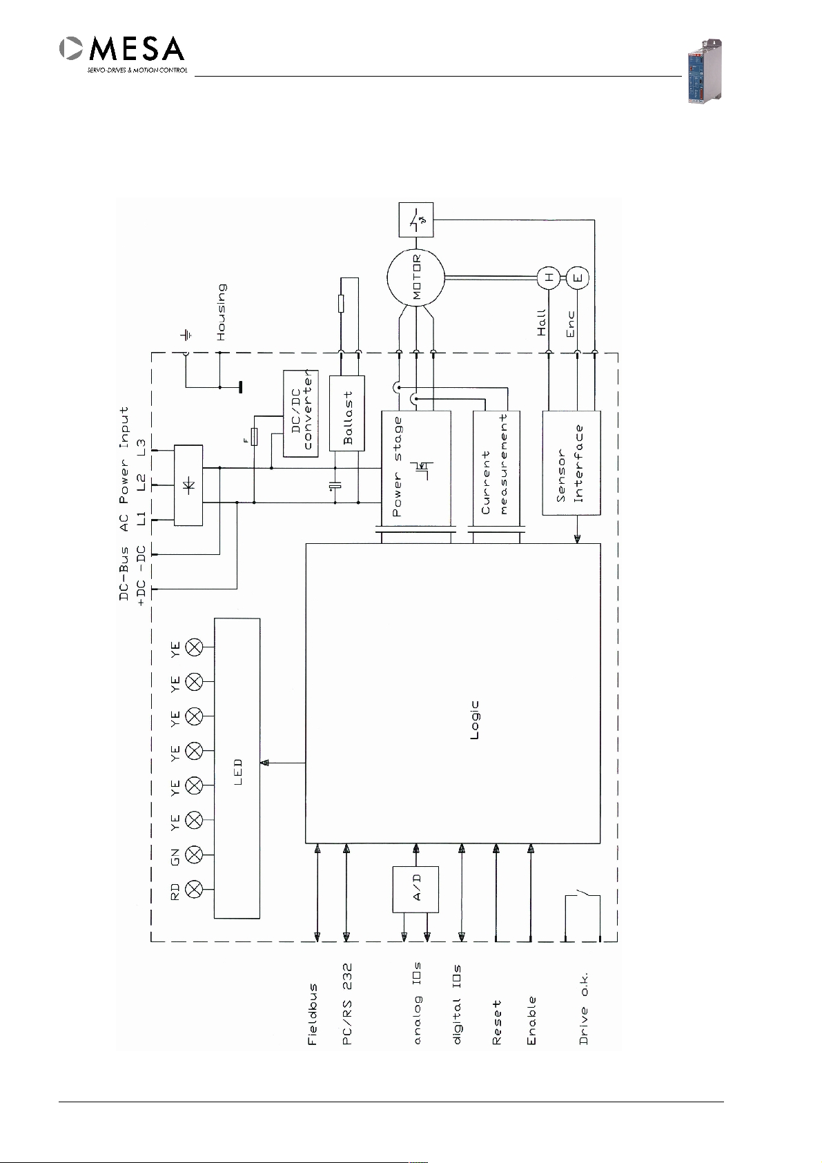
4. Functional principle and basic functions
4.1. Block diagram
MSD4 V1.010
Page 11
4.1.1. State machine
The internal control of a MSD4 servo amplifier takes place in precisely defined states. Also
the transitions between the states are precisely defined. This functionality is implemented as
a state-machine.
After power-up the servo amplifiers is situated in a defined state. Every appearing event
switches the state-machine in a defined way into a defined state.
A detailed functional description of the state-machine can be found in the communication
profile manual of the particular field bus type. The section “Device Control” is entirely
concerned with this theme. The main states of the servo amplifier are “Operation Enabled”
and “Switched On”. The switching between these both states will be controlled by the
“Software-Enable” signal.
4.1.2. Operation modes
Depending on the function, the servo amplifier should provide, the correct operation mode
has to be chosen. Changes of the operation mode are generally possible in every operation
mode, if the state-machine is not in the “Operation Enabled” state.
The following steps are necessary to change the current operation modes:
1. Switch off the “Software-Enable” signal (State-machine leaves “Operation Enabled” state)
2. Change to the desired operation mode – check the right setting
3. Switch on the “Software-Enable” signal (State-machine goes into “Operation Enabled”
state)
The following operation modes are selectable:
● Simple speed control
The servo amplifier operates as speed controller and the speed actual value follows the
speed set value, given by the communication interface.
Start conditions Start Stop
Amplifier in speed control
Speed set value “0”
Speed set value “0”
mode
Enable Amplifier
Disable Amplifier
Amplifier disabled
Give a speed set value
● Simple current control
The servo amplifier operates as current controller and the current actual value follows the
current set value, given by the communication interface.
Start conditions Start Stop
Amplifier in current control
Current set value “0”
Current set value “0”
mode
Enable Amplifier
Disable Amplifier
Amplifier disabled
Give a current set value
MSD4 V1.0
11
Page 12
● Homing mode
Start conditions Start Stop
Amplifier in position control
mode
Set the start-bit in control
word
Stops automatically after
sequence
Sequence chosen
Reset the start-bit in control
word after sequence start
Amplifier enabled
● Sequential position control
The servo amplifier operates as position controller and the position actual value follows
the position set value, given by the communication interface. The position control
normally takes place as sequence. That means there will be given only the target position
as set value. The movement itself will be calculated by the servo amplifier and can be
additionally influenced by the parameters speed, acceleration and deceleration. Servo
amplifiers with CAN interface are able to proceed movement profiles, which calculated by
an external control devices. In this case the control device sends interpolated trajectory
data to the servo amplifier in close succession.
Start conditions Start Stop
Amplifier in position control
mode
Toggle the start-bit in
control word
Stops automatically after
sequence
Sequence chosen
Amplifier enabled
● Speed control via analog input
The servo amplifier operates as speed controller and the speed actual value follows the speed
set value, given by the analog interface.
Start conditions Start Stop
Amplifier disabled
(„Hardware-Enable“ off)
● Current control via analog input
Hardware-Enable on
Give a speed set value
Disable Amplifier
The servo amplifier operates as current controller and the current actual value follows the
current set value, given by the analog interface.
Start conditions Start Stop
Amplifier disabled
(„Hardware-Enable“ off)
Hardware-Enable on
Give a current set value
Disable Amplifier
MSD4 V1.012
Page 13

4.1.3. Set value demand for speed, current and position
Set values can be given via field bus, via PC interface (RS 232) and via analog input. There
can be given only set values for speed and torque on using the analog interface.
4.1.3.1. Speed settings
The parameter “Mechanical speed limit” will be normally delivered from the motor database.
This setting is a limit for all given speed set values. The compliance with this parameter will
be observed by the servo amplifier automatically in all operation modes.
The speed actual value will be detected by the chosen feedback device.
4.1.4. Control priority
The control priority determines the behaviour of the servo amplifier after activation of the
“Hardware-Enable” signal. If the parameter is set to “Stand-Alone” the state-machine will be
switched automatically into the “Operation Enabled” state. If the parameter is set to “Feldbus
Master PLC” the state-machine can be switched by the control device or by the user
interface.
4.1.5. Error-RESET
If the servo amplifier is situated in an error state, a RESET can be proceeded via field bus or
PC interface. There is also a hidden button at the front plate, which also provides the reset
function. This button is only active if the servo amplifier works in stand-alone mode. The
RESET procedure will only be successful, if the error cause is not still active.
4.1.6. Power-On RESET
A switch “off” and “on” of the supply voltage will also reset all servo amplifier errors. On using a
separate +24 V auxiliary voltage, both power supplies (main power and auxiliary power) have to be
switched “off” and “on”. The RESET procedure will only be successful, if the error cause is not still
active.
4.2. In- and Outputs
4.2.1. Digital In- and Outputs
The servo amplifiers of the MSD4 series containing a couple of digital in- and outputs. There
are two kinds of in- and outputs. The first type is the determined type, because it has a
determined function (like Limit switch, Homing switch or Stop). The other type is the general
type. The function of the general digital in- and outputs is user-defined and can be used
mainly for the extension of the machine functionality.
4.2.2. Analog inputs
There are two symmetric +/-10 V analog inputs. The analog input ANIN1 is normally
configured as set value input for speed or torque. The analog input ANIN2 is user-defined
and can be used for measurement data logging for the control device.
MSD4 V1.0
13
Page 14
4.2.3. Actual value acquisition
4.2.3.1. Encoder
Encoder devices deliver position- and speed information to the servo amplifier. The servo
amplifiers of the MSD4 series support encoders which are conform with the RS485 specification
(A, A/,...). The encoder resolution can be set between 250 and 5000 ppr by the user interface
software. The maximum input frequency of the encoder inputs is 700 kHz (about 17000 rpm
maximum speed with a 2048 ppr encoder device).
Using of brushless DC motors needs additional HALL signals for the commutation information.
4.2.3.2. Hall feedback
The HALL feedback delivers the commutation information for brushless DC motors. Servo
amplifiers of the MSD4 series support HALL signals with TTL level or with open collector outputs.
The mounting of the HALL sensors should be 60° or 120° and can be set by the user interface
software.
Attention ! The power consumption of the 5V supply for encoder device and HALL
sensors must not exceed 210 mA.
4.2.3.3. DC-Tacho
On using a brushed DC motor the actual value acquisition can be implemented with an
encoder or preferably with a DC tacho generator. The tacho scaling setup has to be proceed
by the user interface software. An additional resistor between TJ- (X1 Pin 6) and TJ+ (X1 Pin
18) is necessary for the tacho voltage adaptation. The value of this resistor can be taken
from the following table or from the MESABO software.
Tacho voltage at N
max
Resistor value
< 12,0 V open
12,0 V...17,9 V 180 kΩ 1% 0,25W
18,0 V...25,9 V 75 kΩ 1% 0,25W
26,0 V ... 37,9 V 43 kΩ 1% 0,25W
38,0 V ... 51,9 V 27 kΩ 1% 0,25W
52,0 V ... 73,9 V 18 kΩ 1% 0,25W
74,0 V ... 80,0 V 12 kΩ 1% 0,25W
Attention ! The maximum voltage at the tacho input of the MSD4 must not
exceed 80V for long times. Too high tacho voltages will damage the servo
amplifier. Missing resistors or wrong resistor values will cause false
measurement values
MSD4 V1.014
Page 15
4.2.3.4. Armature voltage control with IxR compensation (opt. Var. 016 / 018)
On using brushed DC motors the armature voltage control allows a reasonable speed control. The
speed information will be derived from the back electromotive force in this case. The IxR
compensation counterbalances the voltage loss in the winding and wiring of the motor.
The armature voltage control with IxR compensation is only available with the variants 016 and
018 for brushed DC motors.
4.2.3.5. Current measurement
The motor current will be measured with resistors in the motor circuit. The signals will be
rehashed and transferred by opto-isolated operational amplifiers.
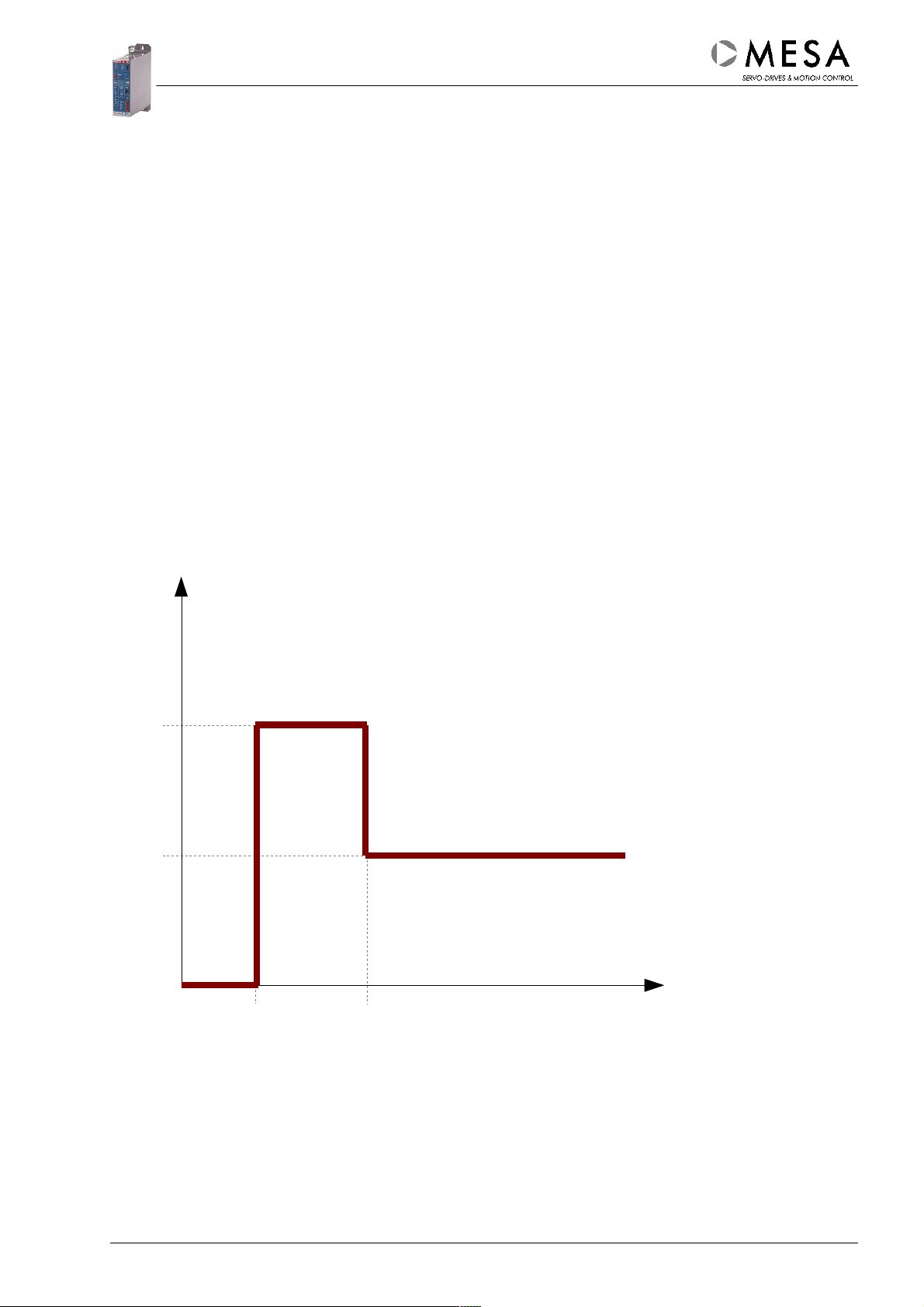
4.2.3.5.1. I
Maximum current setting
Amax
Servo amplifiers of the MSD4 series are able to deliver the double of their nominal current for a
short time. This feature enables short acceleration and deceleration times. The current value of
the type label means the nominal current (50% of the maximum current). The maximum output
current can be set between 10...100 % I
4.2.3.5.2. I
(I2t)-Function
Arms
max
.
I
t1 = Start of acceleration
t2 = Start of limitation
I
Amax
= t
– t1 (without pre-load)
2
I
Aeff
t
t1
The I²t function emulates the effective value of the motor current independently on the real
curve shape. The effective value limitation will be set by the user interface software between
10...50 % I
current and the maximum current.
. The actual effective current depends on the pre-load, the parametrized peak
max
t2
MSD4 V1.0
15
Page 16
4.2.4. “Ready”-Output
“Ready” Output (Relais contact):
● Closed : Servo amplifier is ready for operation (no error)
● Open : Servo amplifier is not ready for operation (If there are errors, during start-up
phase or if there is no supply voltage.)
4.2.5. Hardware-Enable
Connecting +24 V DC to the “Hardware-Enable” input activates the power stage if the servo
amplifier operates in “Stand-Alone” mode. The servo amplifiers begins immediately to work
in the actual operation mode.
Attention! The motor might move directly after switching on the “HardwareEnable” signal.
Switching off the “Hardware-Enable” signal deactivates the power stage.
Attention ! The motor will be decelerated only by friction in this case. In field
bus mode or on using the user interface software the “Hardware-Enable”
signal has to be activated. The motor can not be moved otherwise.
The “Hardware-Enable” signal controls an eventually existing motor brake at the same time.
4.2.6. Machine Switches
4.2.6.1. Stop-Input
The Stop function will be deactivated by connecting +24 V DC to the stop input. An open
input or 0V at the stop input stops the motor movement immediately with maximum current.
The function works independently on the actual moving direction. The internal current set
value will be set to “0” if the servo amplifier works in the current controller mode – the motor
will be decelerated by friction in this case.
If the servo amplifier is currently in a homing procedure a procedure error will be generated.
The behaviour of the servo amplifier for an occurring stop event depends on the actual
operation mode:
● Current control mode: The parametrized current set value becomes active again.
● Speed control mode : The servo amplifier starts the movement with the parametrized
speed again.
● Position control mode : The interrupted sequence can be restarted by setting the start
command again (bit in control word)
● Homing mode : After RESET of the procedure error the homing procedure can be
restarted.
MSD4 V1.016
Page 17

4.2.6.2. Hardware-Limit Switch
To enable the corresponding moving direction the related limit switch input has to be
connected to +24 V DC.
An open input or 0V at the limit switch input prevents every movement in the locked
direction. The internal current set value will be set to “0” if the servo amplifier works in the
current controller mode – the motor will be decelerated by friction in this case. The servo
amplifier can only be moved in the opposite direction. If a limit switch will be reached during
a running homing procedure a procedure error will occur.
The behaviour of the servo amplifier for an occurring hardware-limit-switch event depends on
the actual operation mode:
● Current control mode: The parametrized current set value becomes active again.
● Speed control mode: The servo amplifier has to be moved in the opposite direction firstly.
The software contains a lock function, which prevents each movement in the locked
direction (Overrun of the limit switch).
● Position control mode: The interrupted sequence can be restarted by setting the start
command again (bit in control word)
● Homing mode: After RESET of the procedure error the homing procedure can be
restarted.
4.2.6.3. Homing Switch
In position controller mode this input can be used for the homing procedures. Detailed information
about homing are contained in the PC user interface software (MESABO) manual.
4.3. Temperature sensors
The servo amplifier contains a temperature sensors for the temperature monitoring of the power
electronics. Additionally a temperature sensor for the temperature monitoring of motor winding can
be connected. There can be set a maximum temperature and a time constant (0...16 s) for each
temperature sensor separately. If the detected temperature exceeds the parametrized limit longer
than the time constant, an over temperature error will be generated by the servo amplifier.
4.3.1. Motor temperature sensor
The evaluation circuit supports the following NTC resistor: R = 220k (10%). If there is a different
type built in the motor, the user interface software displays wrong values.
Recommended types:
EPCOS 220k NTC d=5,5mm (No.: B57164K0224+000)
EPCOS 220k NTC d=3,5mm (No.: B57891M0224+000)
Commonly the temperature display at the user interface software supports arbitrary temperature
sensors (NTC, PTC, Temperature switches). There are some temperature curves in the contained
database. If you need other temperature curves, do not hesitate to ask our support department.
4.4. General digital in- and outputs
Optionally the MSD4 contains eight additional digital in- and outputs. Normally they work as 24V
inputs but they can be programmed separately as 24V outputs by the user interface software.
The in- and outputs can be used as general in- and outputs by the superior control device.
MSD4 V1.0
17
Page 18

4.5. Control- and Diagnosis Interface
4.5.1. Parameters
The MSD4 parameters will be stored in non-volatile EEPROM memory. During the boot-up phase
the parameters will be loaded into the RAM area and be activated. The parameters can be
changed and activated by the communication interface, if all other conditions are fulfilled. The
changeability of a parameter depends additionally on state of the “Software-Control”, the
“Software-Enable” signals and on the access type of the parameter (ro/rw). Changed parameters
have to be stored into the EEPROM before power off if they should not get lost.
4.5.2. Monitor Outputs
The monitor outputs support the user during the bring-in-to-use procedure. Two internal
signals can be brought out as analog signal and recorded with an oscilloscope or a XY
writer.
Normally the monitor outputs are configured to show the signals „Actual speed“ and „Actual
current“. The configuration of the monitor outputs is described in the software manual.
MSD4 V1.018
Page 19

5. Configuration of the Servo Amplifier
The parametrizing of the servo amplifier should be made with the contained PC user interface
software MESABO. Use the most actual version of the MESABO software each time. The
MESABO software manual contains all necessary information for configuration and optimization of
the servo amplifier.
The servo amplifier starts every time in this operation mode, which is stored in the EEPROM. To
start the servo amplifier directly in the desired operation mode, it is recommended to store this
mode into the EEPROM after the configuration of the servo amplifier was finished.
If the user interface software detects a servo amplifier for the first time, a parameter file with the
“org” extension will be created automatically in the “devices” directory. It contains the delivery
parameters of this particular servo amplifier.
Attention! The PC interface is only for parametrizing and diagnosis. Parameter
changes influences the behaviour of the servo amplifier immediately. Wrong
settings cause unpredictable behaviour or even damages and injuries.
5.1. Basic configuration – First Steps
● Wiring the servo amplifier corresponding to the local conditions
● Deactivate the “Hardware-Enable” signal
● Install the user interface software MESABO
● Connect PC and servo amplifier
● Connect the power supply (pay attention to the grounding!)
● Wait until the green “OK” LED lights
● Start the PC user interface software MESABO
The MSD4 will be controlled by the field bus interface after the start-up. The user has to taken the
“Software-Control” before the parameter setting is possible.
Attention ! Taking the “Software Control” interrupts immediately all field bus
operations. Even running operations will be interrupted.
During the start-up the following operations will be proceeded:
● Initializing the DSP
● Loading the parameters from EEPROM into the RAM area
● Initializing the control loops
● Initializing and activating the communication interfaces (Field bus / PC interface)
● Checking the servo amplifier state and the input signals
● Setting up the outputs, the monitor signals and the LEDs
● Initializing the state machine
The start-up procedure takes several seconds – the servo amplifier is not operational during
this time.
MSD4 V1.0
19
Page 20

6. Power supply
The mains voltage has to be adapted by a transformer to the input voltage of the servo module on
demand. An auto-transformer can be used.
6.1. Mains transformer
It is possible to use transformers with electrically isolated windings and auto-transformers for the
mains adaptation. The transformers have to be conform with the VDE 0550 standard. On using
three-phases transformers it is necessary to use star connection with earthed star point at the
secondary side.
The internal mains filter causes a high leakage current (in worst case up to 14 mA). An eventually
built-in earth leakage circuit breaker may interrupt the power circuit. The servo amplifier has to be
fix installed. An interruption of the earth circuit (Housing / PE / GND) is not allowed.
6.2. Ballast circuit
During motor deceleration the kinetically energy of the motor will be transformed into
electrically energy. In this case high voltages can accrue by induction. These voltage can
cause an over voltage error in the servo amplifier. The servo amplifiers of the MSD4 series
contain a complete ballast system with internal ballast resistor to prevent this. If the
application causes higher braking energies an external (more powerful) resistor can be
connected between X22 Pin 2 and 3.
Attention ! The connection between X22 Pin 1 and 2 has to be rejected if an
external ballast resistor will be connected.
Type Internal
Resistor
MSD4 30xx 22 Ohm 30 W 22 Ohm 200 W
MSD4 50xx 39 Ohm 30 W 39 Ohm 200 W
*
higher continuous powers with external ballast resistor on demand
Max. continuous
load
External
Resistor
Max. continuous
load
*
*
External ballast resistors should have a minimum load of 375 W.
The continuous ballast load will be electronically limited. It is about 30 W for internal ballast
resistor and about 200 W for the external ballast resistor. If these limits will be exceeded during
operation an over voltage error occurs.
● The wiring of the external ballast resistor has to be shielded if it is longer than 0,5 m.
● If the ballast resistor will be mounted outside of the cabinet, it has to be covered with
perforated sheet metal to prevent emissions and accidental contact.
● The ballast resistor has to be protected against accidental contact in any case,
because it gets very hot during normal operation.
Attention ! The connector X22 and the ballast resistor have high voltage!
MSD4 V1.020
Page 21

6.3. +24 V DC Auxiliary Voltage (Electronic supply)
The +24 V auxiliary voltage supplies the electronic of the servo amplifier if the power voltage is off.
The purpose is to store and to detect the actual position if the power voltage is inactive. The
auxiliary voltage controls also the motor brake.
The entire power consumption can be parted into the power consumption of the MSD4 electronics
and into the power consumption of the motor brake:
● The power consumption of the MSD4 electronics is max. 0,8 A (24V DC ±20 %).
● The power consumption of the motor brake depends on the used model and has to be
lower or equal to 1,5 A. The tolerance of the auxiliary voltage depends on the motor brake
in this case.
6.4. Control of the motor brake
The servo amplifiers of the MSD4 series contain a semiconductor switch (+24V) for the motor
brake control. The supply of the motor brake will be ensured by the +24V auxiliary voltage
(connector X24 at the front panel). The internal voltage loss is lower than 0,5V.
The semiconductor switch is electronically protected.
The motor brake can be controlled by the field bus or together with the “Software-Enable” signal.
Normally it will be controlled by the field bus. If the user takes the “Software-Control” in the user
interface software or in the “Stand-Alone” mode, the motor brake will be controlled automatically
with the “Hardware-Enable” signal.
Attention ! The power consumption of the motor brake must not exceed 1,5 A.
6.5. Fuses
Pos. MSD4.. Size Current / Voltage Function / Notice
06xx 5 x 20 4,0 A MT / 250 V AC
F1
F2 xxxx 5 x 20 2,0 A MT / 250 V AC +24 V auxiliary voltage for motor brake and
Power stage (external fuse) - has to be installed by the user
F xxxx 16 A T / 400 V AC external fuse
12xx 6,3 x 32 1,6 A F / 500 V DC
30xx 6,3 x 32 1,6 A F / 500 V DC
50xx 6,3 x 32 1,6 A FF / 1000 V DC
DC/DC-Converter - This fuse has to be changed
only by our service department
electronics
MSD4 V1.0
21
Page 22

The fuses are accessible after rejecting the front cover! Fuse F1 (special type) has to be changed
only in the factory after checking the DC/DC converter.
MSD4 - Power board
Attention ! The connectors at the servo amplifier must not connected or
disconnected under load. Wait about 3 minutes after switching off the power
supplies for the discharging of the capacitors!
MSD4 V1.022
Page 23

7. Standard settings
The following table shows the standard settings of the most important parameters. For
special applications or modifications other settings are possible. Ask our service department
for detailed information.
Name Function Default Notice
Communication
RS 232 PC Communication Baudrate 19200 automatically
Power stage
Power stage
temperature
Temperature sensor
(power stage)
Motor temperature Protection of the
Temperature sensor
(motor)
Mode Controller type Speed controller Position / Current
Current loop P-Gain 4500
Imax Max. output current 100 % (Imax) 20...100 % (Imax)
Irms Output current 50 % (Imax) 20...50 % (Imax)
Irms-Limitation Protection of the
Mode Controller type PIDFF-Mode P-Mode
P P-Gain 15000
I I-Gain 100
D D-Gain 0
FF Feed Forward Gain 0
Max. speed Speed limitation 14.000 rpm 500...14.000 rpm
Feedback resolution Resolution of the
Mode Controller type PFF
P P-Gain 125
FF FeedForward Gain 0
Protection of the
electronics
Protection of the
electronics
motor
Protection of the
motor
Operation mode
Current loop
I-Gain 500
electronics
Speed loop
position detection
Position loop
75 °C Or lower
NTC PTC
Motor
95 °C max. 135 °C
NTC PTC
Limitation Interruption
2048 ppr In several steps from
controller
250 to 5000 ppr
CAN-Bus-Interface
Configuration Baudrate 1 MBaud 0,8 MBaud
NODE Address 125
Attention! A changed field bus address will be only valid after Power-On RESET.
MSD4 V1.0
23
Page 24

8. Bring-in-to-use
Attention ! Check the earth circuit of the housing before connecting the servo
amplifier to any voltage (Servo amplifier and motor and PE).
Check before switch-on...
● The correctness of the earth connection!
● The correctness of the wiring!
● The conformity of the transformer output voltage / mains voltage and the nominal voltage
of the servo amplifier!
● The conformity of the servo amplifier current settings (maximum and rated current) and the
nominal current values of the motor!
● The correctness of the application settings!
● The correctness of the settings and wiring of all external switches!
● The movability of the motor axis! (Separate the motor axis from the machine if possible!
Limit the maximum current down to uncritical values (i.e. 20%) in all other cases.)
● The deactivation of the “Hardware-Enable” signal!
Attention! The connectors at the servo amplifier must not connected or
disconnected under load. Wait about 3 minutes after switching off the power
supplies for the discharging of the capacitors!
The power supply can be switched on if all these tests were successfully finished. The user
should perform a same-time measurement of the intermediate circuit voltage.
If the “Ballast-On” LED lights, check again the power supply output voltage and/or the ballast
threshold.
If the „OK“-LED lights, the servo amplifier is ready for operation.
Attention ! The „Hardware-Enable“ signal must only be activated after
connecting the power voltage.
MSD4 V1.024
Page 25

9. Description of the Connectors
9.1. MSD4 Connectors
Name Function Pos. Type Notice
X 1 Motor sensor top D-Sub female 25 Pins Slide lock
X 2 Control signals top D-Sub male 25 Pins Slide lock
X 3
X 4 Machine signals front Plug RM 3,5 10 Pins Screw lock
X 5 Digital I/Os front Plug RM 3,5 10 Pins optional
X 6 CAN (1) bottom D-Sub female 9 Pins Slide lock
X 7 CAN (2) bottom D-Sub male 9 Pins Slide lock
X21 Supply bottom Plug RM 7,6 mm 5 Pins Power Combicon
X22 Ballast bottom Socket RM 7,6 mm 3 Pins Combicon
X23 Motor top Socket RM 7,6 mm 8 Pins Combicon (optional Power
X24 Aux. +24 V front Plug RM 3,5 mm 2 Pins Screw lock
RS 232
alternativ USB
front
9.2. X1 Motor Sensor
D-SUB 25 pins female
D-Sub male 9 Pins
USB-B female
Service
Combicon)
Pin Name Function Notices
1 Z Input Encoder Index Z (RS422)
2 A Input Encoder A (RS422)
3 B Input Encoder B (RS422)
4 GND Ground
5 +Ub Output +5 V Encoder / HALL supply max. 210 mA (Pin 5 und 7)
6 TJ- Input Tacho adaptation negative
7 +Ub Output +5 V Encoder / HALL supply max. 210 mA (Pin 5 und 7)
8 H1 Input HALL 1
9 +24V Output +24 V Auxiliary voltage max. 20 mA
10 R1 Output Resolver supply 1 *
11 T- Analog Input DC Tacho negative potential
12 COS+ Input Resolver cosinus positive *
13 COS- Input Resolver cosinus negative *
14 /Z Input Encoder Index /Z (RS422)
15 /A Input Encoder /A (RS422)
16 /B Input Encoder /B (RS422)
17 GND Ground
18 TJ+ Input Tacho adaptation positive
19 H3 Input HALL 3
20 H2 Input HALL 2
21 R2 Output Resolver supply 2 *
22 MT1 Input Motor temperatur sensor
23 T+ Analog Input DC Tacho positive potential
24 SIN+ Input Resolver sinus positive *
25 SIN- Input Resolver sinus negative *
* The resolver interface is not available in the moment
MSD4 V1.0
25
Page 26

9.3. X2 Control signals
D-SUB 25 pins male
Pin Name Function Notice
1 MON1 Analog output programmable, normally current monitor +/- 4,36 V
2 IO2 In / Output programmable digital in/output 24V (also X4 Pin 2)
3 MON2 Analog output programmable, normally speed monitor +/- 4,36 V
4 /Z Output Encoderindex /Z (RS422)
5 Z Output Encoderindex Z (RS422)
6 /A Output Encoder /A (RS422)
7 A Output Encoder A (RS422)
8 /B Output Encoder /B (RS422)
9 B Output Encoder B (RS422)
10 IO1 In / Output programmable digital in/output 24 V (also X4 Pin 7)
11 GND Ground
12 PAR Input Parameter switching (optional)
13 ERESET Logic input Error-RESET +24V / 0V
14 15 AGND Ground / Analog part
16 ANIN1- Analog input programmable, negative input (+/-10V differential)
17 ANIN1+ Analog input programmable, positive input (+/- 10 V differential)
18 BE1 Output Amplifier ready, dry contact
19 BE2 Output Amplifier ready, dry contact
20 Freigabe Logic input Amplifier enabled +24V (also X4 Pin 8)
21 +24V Output +24 V Auxiliary voltage max. 20 mA
22 23 ANIN2+ Analog input programmable, positive input (+/- 10 V differential)
24 ANIN2- Analog input programmable, negative input (+/-10V differential)
25 GND Ground
MSD4 V1.026
Page 27

X1
Motor
sensor
1
X23
Motor
and
Power
2
3
4
5
6
7
8
MSD4 V1.0
X2
Control
27
Page 28

9.4. X3 RS232
D-SUB 9 pins male
Pin Name Function Notice
1 n.c.
2 RX Data input RS232 receive data
3 TX Data output RS232 send data
4 n.c.
5 GND Ground Reference ground
6 n.c.
7 n.c.
8 n.c.
9 n.c.
The MSD4 is alternatively available with USB interface (USB-B plug).
9.5. X4 Digital In and Outputs
10 pin multi-pin connector / 3,5 mm grid dimension
Pin Name Function Notice
1 GND Ground
2 IO2 In / Output Programmable digital in/output 24 V (also X2 Pin 2)
3 /REF Input 0V or open: reference switch active
4 /E- Input 0V or open: negative limit switch active
5 /E+ Input 0V or open: positive limit switch active
6 /STOP Input 0V or open: stop active
7 IO1 In / Output Programmable digital in/output 24 V (also X2 P. 10)
8 Enable Input Amplifier enabled +24 V (also X2 Pin 20)
9 /Capture Input 0V or open: Capture active
10 +24V In / Output If output: Imax = 20 mA
9.6. X5 Digital In and Outputs (optional)
10 pin multi-pin connector / 3,5 mm grid dimension
Pin Name Function Notice
1 GND Ground
2 GIO0 In / Output Programmable digital in/output 24 V
3 GIO1 In / Output Programmable digital in/output 24 V
4 GIO2 In / Output Programmable digital in/output 24 V
5 GIO3 In / Output Programmable digital in/output 24 V
6 GIO4 In / Output Programmable digital in/output 24 V
7 GIO5 In / Output Programmable digital in/output 24 V
8 GIO6 In / Output Programmable digital in/output 24 V
9 GIO7 In / Output Programmable digital in/output 24 V
10 +24V In / Output If output: Imax = 20 mA
MSD4 V1.028
Page 29

1
X24
Auxiliary
supply
2
X3
RS 232
10
9
8
7
6
5
4
3
2
X5
Digital I/O's
(optional)
10
9
8
7
6
X4
Digital I/O's
5
4
3
2
1
MSD4 V1.0
1
29
Page 30

9.7. X6 / X7 CAN Bus
D-SUB 9 pins female (X6) / D-SUB 9 pins male (X7)
Pin Name Function Notice
1 2 CAN_L CAN Low
3 CGND CAN GND
4 5 Shield
6 0GND ext. CAN supply - Not used
7 CAN_H CAN High
8 9 +Ucan ext. CAN supply + Not used
9.8. X21 Power Supply
Power Combicon 5 pin connector
Pin Name Function Notice
4 +DC
5 -DC DC In / Output DC-BUS (Rectifier, optional: intermediate voltage circuit)
6 L1 AC Input
7 L2 AC Input
8 L3 AC Input
DC In / Output
DC-BUS (Rectifier, optional: intermediate voltage circuit)
Power supply phase 1 Mind the nominal value!
Power supply phase 2 Mind the nominal value!
Power supply phase 3 Mind the nominal value!
9.9. X22 Ballast
Combicon 3 pin connector
Pin Name Function Notice
1 Int Ballast internal ballast resistor (link between Pin 1 and 2)
2 RB Ballast common contact (ballast resistor)
3 Ext Ballast external ballast resistor (between Pin 2 and 3)
9.10. X23 Motor Connector
Combicon (optional Power Combicon) 8 pin connector
Pin Name Function BLDC Motor DC Motor
1 U Motor phase Phase U A1 (positive pole)
2 V Motor phase Phase V A2 (negative pole)
3 W Motor phase Phase W
4 PE Motor earth Equipotential bonding between motor and servo amplifier
5 0V Motor brake- Motor: brake- (GND)
6 +Br Motor brake+ Motor: brake+ (+24V)
7
8 0V Motor temperature Motor: Temperature sensor (GND)
Motor temperature Motor: Temperature sensor
9.11. X24 Auxiliary Voltage +24 V
2 pin multi-pin connector / 3,5 mm grid dimension
Pin Name Function Notice
1 +24 V Input External +24V input for motor brake and electronic supply
2 GND Input Ground (internally connected with PE potential)
MSD4 V1.030
Page 31

X21
Power
supply
8
7
6
5
4
3
X7
CAN
X8
CAN
MSD4 V1.0
X22
Ballast
2
1
31
Page 32

10. Earthing and Installation according to EMC Norms
10.1. General Indications
It is important that the installation of the servo amplifiers of the MSD4 series is made
according to the electrical safety regulations and by qualified personnel which is familiar with
installation, assembly, commissioning and operation of the equipment. National and local
regulations have to be be respected.
Please follow strictly the further instructions, they are important to assure the correct
operation of the MSD4 and so far of the complete machine.
The electromagnetic compatibility of the drive system depends - besides of the MSD4 servo
amplifier - on the following conditions:
● Total cable length and the total capacity to ground.
● Low-impedance earthing of all components, power supply and control device.
● Shielded cables and housings or a completely shielded control cabinet.
● Mind the cable routing – Keep distance between power, control and mains cables.
10.2. General Rules
● The following regulations have to be respected:
● Installation of the device(s) in a closed metal control cabinet or machine
● Use the same ground potential for all components (motor, drive, control) by central
earthing, please check it by measuring on commissioning.
● Contact the service for more information about the filter mode.
● The electromagnetic compatibility complies with the generic standards EN 61000-6-3,
EN 61000-6-4.
10.3. Control Cabinet
● The control cabinet must be equipped with a metal mounting panel with PE edge.
● The mounting panel in the control cabinet is the reference station (GND) for all
signals, it is connected in a conductive way with the PE edge and the cabinet
housing.
● The control cabinet with the mounting panel and the machine must be earthed and
connected (for example with short ground copper strips).
● The shields of all cables leaving the control cabinet must be connected 360° on the
mounting panel, no matter if they are earthed otherwise.
● Shield connections must not be interrupted.
● All cable connections have to be executed as short as possible.
● Outside of the control cabinet the cables should be led directly to the metal parts, as
large distance increases the unwanted emission. For special demands metal cable
channels can be used.
● If cables are led via additional terminals or switches, it is important to assure
sufficient distance between motor cable, mains cable and control cable. Due to the
fact that the cables are not shielded on this position, especially emissions of the
motor cables may have effects on other cables. The cables must be shielded directly
MSD4 V1.032
Page 33

before and after the interruption on the mounting panel. This kind of interruptions
should be avoided. If this is not possible, special shields (housing) can be mounted
according to producer's advice.
● Use external filters or connectors with built-in filters for the external control
connections on demand.
● Use additional chokes directly at the output pins of the servo amplifier in the motor
phases U, V and W on demand. The cores of the chokes have to be mounted in the
cabinet and have to be earthed. Additionally filter capacitors should only be used
after request.
● Use additional mains filters with high damping factor on demand.
For additionally information ask your distribution partner!
10.4. D-SUB Cable shielding
● Use only metallic D-Sub housings or
housings made of metal-coated plastics
● Use only shielded cables
● Contact the shield completely around the
cable
● Use only twisted pair cables with common
shield for the digital I/O's
● Do not lay power and control cables in a
parallel way
● Care for low-impedance earth connections
MSD4 V1.0
33
Page 34

11. Wiring
11.1. Cable cross sectional areas
Minimum cross sectional area for power cabling
Cable cross sectional area Allowed R.M.S. current
1,0 mm
1,5 mm
2,5 mm
2
2
2
10 A
15 A
20 A
11.2. Motor cable
The maximum length of the motor cable depends on the used cable type, the motor type and the
servo amplifier. For detailed information ask our support department.
Attention! The motor cable has to be shielded and the shield has to be
contacted at both sides in a large area.
11.3. Control cables
● Control cables, especially if they are leaving the cabinet have to be shielded or equipped
with additional filters. The shield has to be connected to the amplifier and to the mounting
plate. The shield of the control cable X2 has to be connected to metallic plug housing.
● Unshielded control cables should be avoided. The distance to the power cables (X21, X22,
X23) must be greater than 5 cm.
● The wiring of the encoder has to be made strictly as a shielded twisted pair cable.
11.4. MSD4 CAN Bus Wiring
11.4.1. General
There are two ways for connecting the CAN Bus:
We suggest to use dedicated CAN Bus cable and metallic shielded plugs for best results and
high reliability. The shield must be connected on both ends of the cable in every case.
Field bus cables have to be carried out in shielded twisted pair version and should be
dislocated from power cables. The cable must be terminated with an 120 Ohm 0,25W
resistor on both ends. Stubs are only allowed up to 30 cm.
Attention! Read also carefully the control builders manual for specific
information.
MSD4 V1.034
Page 35

11.4.2. Standard Version
Cable with two twisted pairs and common shield. We suggest an equipotential bonding to
minimize circulating currents in the shield.
Cable type – order example
Flexible wiring Non flexible wiring
Label Lütze Superflex Bus © PUR
2x2x0,25mm²
Outside diameter 5,9mm 5,9mm
Ordering number 104220 2170261
Lapp 2x2x0,22mm²
11.4.3. Simplified Version
Cable with one twisted pair and common shield. This version should only be used if the
distances between the servo amplifiers are short and if the equipotential bonding is perfect.
Cable type - order example
Flexible wiring Non flexible wiring
Label Lütze Superflex Bus © PUR
1x2x0,25mm²
Outside diameter 6,0mm 5,7mm
Ordering number 104202 2170272
Lapp UNITRONIC BUS
CAN1x2x0,22mm²
Label Lapp UNITRONIC BUS-FD P
CAN1x2x0,25mm²
Outside diameter 6,4mm
Ordering number 2170260
MSD4 V1.0
35
Page 36

12. Connecting
12.1. Connection to Mains Power
12.2. DC Bus Coupling
MSD4 V1.036
Page 37

The DC bus coupling has the following advantages in multi-axis systems:
● Higher DC bus capacity - especially on single-phase power supply
● Simple wiring
● The entire ballast power is available for each axis
Please pay attention to the following facts:
Use the DC bus coupling only for devices with the same nominal voltage.
The entire nominal current of all axis has to be lower than 18 A. There is a maximum of 4 axis
without an additional DC fuse.
Axis 1 Axis 2 Axis 3 Axis 4 Entire I
MSD4 xx10 MSD4 xx06 ----------------- ---------------- 16
MSD4 xx08 MSD4 xx04 MSD4 xx04 ---------------- 16
MSD4 xx06 MSD4 xx04 MSD4 xx04 MSD4 xx04 18
Attention ! The DC bus connectors and the fuse sockets have high voltage!
rms
(A)
MSD4 V1.0
37
Page 38

12.3. Wiring Scheme for BLDC-Motor
(Principle view)
Attention ! Use the eventually provided wiring sheet and the adjustment notes
every time.
MSD4 V1.038
Page 39

12.4. Wiring Scheme for DC Motor
(Principle view, see also Variants 016 and 018)
Attention! Use the eventually provided wiring sheet and the adjustment notes
every time and mind the minimum inductance Lmin
(1)
.
MSD4 V1.0
39
Page 40

13. Mechanical Dimensions
13.1. Standard Housing
Attention ! The user has to take care for equipotential bonding between the
different machine parts (Control device – Servo amplifier – Motor). If there are
doubts about the activity, an additionally measurement must made for
certification.
MSD4 V1.040
Page 41

13.2. Short Housing (optional)
The short housing contains neither a ballast resistor nor a fan. Normally an external ballast resistor
is necessary. The cooling takes place via the mounting plate or via an side-mounted heatsink.
Under circumstances an external fan is necessary.
Attention! The user has to take care for equipotential bonding between the
different machine parts (Control device – Servo amplifier – Motor). If there are
doubts about the activity, an additionally measurement must made for
certification.
MSD4 V1.0
41
Page 42

14. Known problems and limitations
There are some known problems and limitations concerning the functionality of the servo amplifier.
Please remind the further limitations to prevent an unpredictable behaviour of the servo amplifier.
The problems and limitations could be solved by updates of the firmware or user interface
software in the mean time. For additionally information ask our service department!
Operation notes:
● Set the parameter “Maximum position following error” to a defined value to garant a reliable
function of the safety mechanisms.
● During the CANopen operation mode “Interpolated position mode” all device control
options are internally set to “Switch off PWM“.
15. Troubleshooting
15.1. LED Display
LED Meaning Color Notice
Error Summary error message red Amplifier not ready
OK Amplifier ready green Amplifier ready, „Enable“ possible
LS(-) Limit switch active yellow Negative moving directory locked
LS(+) Limit switch active yellow Positive moving directory locked
Brake Motor brake yellow Motor brake supplied with current
Enable Enabled yellow Amplifier enabled
Ballast Ballast system active yellow Motor will be decelerated
IRMS I2t limit reached yellow Output current limitation (IAeff)
MSD4 V1.042
Page 43

15.2. Error Finding
Use the PC user interface software MESABO for setup and diagnosis of the servo amplifier. Do
not try to use servo amplifiers with damages or servo amplifiers with open housings or wrong
wirings.
Categories Symptoms Measurements
General Mechanical damage Change the amplifier
MSD4 gets too hot Check the parameter settings
Check the mounting situation
Power supply Fuses defective Check wiring and power supply
Limit the maximum current
Servo motor Noises Check the parameter settings
Change the motor
Axis does not move Change the amplifier / motor
Motor brake Motor brake not lifted Check the +24V auxiliary voltage
Lift the brake
Power stage Under voltage Check the power supplies
Check for 3 phase supply
Over voltage Ballast power too high
Use an external ballast resistor
Current loop Over current Check the PI parameter settings
Set the parameters to default values
Speed loop Speed too low Check the Nmax parameter settings
Check the PI parameter settings
Set the parameters to default values
Check the power voltage
Position loop Target position overrun Check the Nmax parameter settings
Check the Imax parameter settings
Field bus No communication Check the wiring
Check the parameter settings
PC interface No communication Check the availability of the COM port
Check the baudrate setting
Read the software manual
Close all programs which are using COM
ports.
MSD4 V1.0
43
Page 44

15.3. Errors
Error Possible reasons
Under voltage error
Intermediate circuit voltage too
low or absent.
Over voltage error
Intermediate circuit voltage too
high.
Over current error
Output current of the power
stage too high.
Ballast error
Ballast current higher than the
limit.
Feedback error
HALL- or encoder signals not
correctly detected or absent.
I2t error
R.M.S. current higher than the
limit.
Following error
Position deviation is higher than
the limit.
EEPROM error
Reading from or writing to the
EEPROM failed. (possible state
after firmware update)
Field bus communication error
Communication via field bus
failed.
Procedure error
Internal procedure was
terminated with an error.
Over temperature amplifier
Temperature of the electronics is
higher than the limit.
Over temperature motor
Temperature of the motor is
higher than the limit.
Loss of supply voltage during acceleration / Defective fuse
Braking energy too high / Mains over voltage / Supply voltage
too high
Short circuit in the motor winding or wiring / wrong current
loop settings or defective power stage
With external ballast: short circuit in the ballast wiring / ballast
resistor too low
Wiring error in the feedback device / Hardware error / Shield
not connected
Acceleration time with maximum current too long / Motor axis
blocked
Load at the motor axis too high / Wrong parameter settings
EEPROM hardware error
Wrong field bus parameter setting / Wiring error
i.e. Homing timeout
R.M.S. current too high / Bad cooling
R.M.S. current too high / Bad cooling
If there occurs an error the internal state machine goes via the “Fault Reaction Active” state into
the “Fault” state (see field bus manual).
Error states will be stored until the next RESET or power-off. Additionally the summary error bit in
the state register will be set. The detailed error information is readable via the communication
interfaces. It is only possible to reset the error state of the servo amplifier if the error condition is
not still active.
MSD4 V1.044
Page 45

The following steps have to be done in error case:
● Detect the error cause (i.e. With the user interface software)
● Fix the error cause (i.e. Change a parameter)
● Run the RESET function
● Check if the amplifier is ready again
After a successful RESET procedure the servo amplifier state machine stays in the state “Switch
On Disabled”.
Several error messages can be disabled (masked) for test purposes:
● Following error : If this error will be masked, the drive moves on, even if the “Maximum
position following error” will be exceeded. The masking of this error makes sense during
the optimization of the servo amplifier.
● Power stage under voltage error: If this error occurs, the MSD4 will not become
operational, neither a “ready” message will be shown. The masking of this error will not be
supported by the MSD4 this time.
Several error states become active not until an internal programmable timer runs out. As long as
the timer runs a warning will be presented. The control device can react to prevent the error state
in this case.
● Over temperature electronics: The over temperature error will be activated if the error
condition is active longer than parametrized time.
● Over temperature motor: The over temperature error will be activated if the error
condition is active longer than parametrized time.
MSD4 V1.0
45
Page 46

16. Variants and Modifications
Devices with variant numbers are devices with functions not according to the standard functions.
They are mostly available for different classes.
Devices with customer-specific modifications are additionally available.
16.1. Variant 016 (MSD4 for DC Motor)
● Using with brushed motors
● Additionally available armature voltage feedback with IxR compensation
● Rectifier and ballast circuit are contained (usable for AC and DC supply, if recovery is not
wanted).
Attention! Using of brushless motors is not possible with this variant.
16.2. Variant 018 (MSD4 for DC Motor and battery operation)
Type I
[A]
max
I
Rated
[A]
U
Rated
[VDC]
U
min
[VDC]
U
max
[VDC]
Fan Inductance
L
[mH] *
min
Ballast
system
MSD4 0610 20 10 24...65 17 75 internal 0,3 / 0,15 Var.018: no
MSD4 0615 30 15 24...65 17 75 internal 0,2 / 0,1 Var.018: no
MSD4 1215 30 15 36..125 36 140 internal 0,4 / 0,2 Var.018: no
* Minimal motor inductance on nominal voltage: first value valid for 8 kHz PWM, second value for 16 kHz PWM
● Using with brushed motors
● Additionally available armature voltage feedback with IxR compensation
● Rectifier and ballast circuit are not included because of the battery operation and of the
ballast voltage for battery recovery.
Attention ! Using of brushless motors is not possible with this variant.
If the device will be powered by a power supply which is not able to tolerate the voltage rising
during the deceleration the variant 016 (with rectifier and ballast circuit) has to be used. The power
supply has to be connected to the pins L1 (X21 Pin 6, positive pole) and -DC (X21 Pin 4, negative
pole).
MSD4 V1.046
Page 47

17. Additional information
Software manual CAN-Bus
Software manual MESABO (user interface software)
17.1. Optional connector sets
For the cable manufacturing (contains all plugs beside X3 and X5):
Connector set MSD4 (MESA article code: 92.02052)
Other connector sets on demand!
MSD4 V1.0
47
Page 48

18. Other products
The following digital servo amplifiers are available for supply voltages from 24 to 65 VDC.
They are available with CANopen or PROFIBUS communication interface.
18.1. BME: Basic Motion Element
(BLDC Motor with integrated servo electronics)
18.2. BDE: Basic Drive Element
(small servo amplifier, same electronics as BME)
18.3. BDE: High Current Device
(BDE High current version, 48 V / 120 A
or 65 V / 100 A
max
max
)
MSD4 V1.048
Page 49

19. Place for your notices:
MSD4 V1.0
49
Page 50

MSD4 V1.050
Page 51

Page 52

Date of issue: 04.09.2008
AN 74.02495 / V1.0
©MESA Automation GmbH
© MESA AUTOMATION GmbH
INFRANOR GROUP - www.infranor.com
12045 Berlin
Maybachufer 48-51
Phone: +49 (0)30 6139080 Fax: +49 (0)30 6231766
http://www.mesa-berlin.de e-mail: service@mesa-berlin.de
 Loading...