

Page 1

1
USER MANUAL
XVR1648
Stand Alone Type
DVR SYSTEM
Page 2

2
HDD , CD/DVD-RW Connect -------------------------------------------------- 12
System -------------------------------------------------------- 23
User ---------------------------------------------------------- 22
Network --------------------------------------------------------- 20
Disk Management -------------------------------------------------- 32
Event ------------------------------------------------------- 26
Setup-System ------------------------------------------------------ 15
Display --------------------------------------------------------- 15
Camera ------------------------------------------------------ 17
Audio ------------------------------------------------------- 19
Configuring the live display ---------------------------------------------- 14
Power On ---------------------------------------------------------------- 13
Live Display --------------------------------------------------------------- 14
Remote Controller description --------------------------------------------- 11
Rear panel description --------------------------------------------------- 10
Front panel description --------------------------------------------------- 9
Product Description -------------------------------------------------------- 9
System Organization ---------------------------------------------------- 8
Product Contents List --------------------------------------------------- 7
Specifications --------------------------------------------------------- 5
Specification & Organization -------------------------------------------------- 5
Setup-Record ------------------------------------------------------ 33
Pre/Post Recording --------------------------------------------- 33
Normal Record---------------------------------------------------- 34
Intensive Record -------------------------------------------------- 36
Panic ------------------------------------------------------- 38
IMPORTANT SAFETY INSTRUCTIONS -------------------------------------------- 4
Panorama 1 search --------------------------------------------------- 40
Normal Search ------------------------------------------------------ 39
Search -------------------------------------------------- 39
Panorama 2 search --------------------------------------------------- 45
Smart search --------------------------------------------------- 46
Page 3

3
Ch Selection -------------------------------------------------- 49
SEQ Start / Stop ---------------------- ------------------------------------ 50
Reserved Data Management ---------------------------------------------- 48
Archiving --------------------------------------------------- 47
Digital Zoom ------------------------------------------------------ 52
Archiving -------------------------------------------------------- 47
PTZ --------------------------------------------------------------- 51
Key Lock ------------------------------------------------------ 53
Panic Rec ------------------------------------------------------ 54
Shutdown ------------------------------------------------------ 55
System Requirement ---------------------------------------------------- 56
Introduction ----------------------------------------------------------- 57
Remote SW Local Setup ----------------------------------------------------- 58
local setup ---------------------------------------------------- 58
Remote SW installation ------------------------------------------------------ 56
Search Method -------------------------------------------------------- 63
Search Option -------------------------------------------------------- 64
Remote SW DVR System Setup ------------------------------------------------ 69
Camera ------------------------------------------------------------ 70
Alarm/Event -------------------------------------------------------- 71
Display ---------------------------------------------------------- 74
Audio ----------------------------------------------------------- 76
User ----------------------------------------------------------- 76
Remote SW DVR Record Setup ------------------------------------------------ 77
Record Mode ---------------------------------------------------------- 77
Normal record --------------------------------------------------------- 79
Intensive record -------------------------------------------------------- 81
Panic record ---------------------------------------------------------- 82
Search Function Introduce ------------------------------------------------ 62
Remote SW Search --------------------------------------------------------- 62
WEB CONNECTION SETUP ---------------------------------------------------83
Page 4
4
IMPORTANT SAFETY INSTRUCTIONS
1) Read these instructions.
2) Keep these instructions.
3) Heed all warnings.
4) Follow all instructions.
5) Do not use this apparatus near water.
6) Clean only with a dry cloth.
7) Do not block any of the ventilation openings. Install in accordance with the manufacturer's instructions.
8) Do not install near any heat sources such as radiators, heat registers, stoves, or other apparatus
that produce heat.
9) Do not defeat the safety purpose of the polarized or grounding type plug. A polarized plug has
two blades with one wider than the other.
A grounding type plug has two blades and a third grounding prong.
The wide blade or the third prong is provided for your safety.
When the provided plug does not fit into your outlet, consult an electrician for replacement
of the obsolete outlet.
10) Protect the power cord from being walked on or pinched particularly at plugs, convenience
receptacles, and the point where they exit from the apparatus.
11) Only use the attachments/accessories specified by the manufacturer.
12) Use only with a cart, stand, tripod, bracket, or table specified by the manufacturer, or sold
with the apparatus.
When a cart is used, use caution when moving the cart/apparatus combination to avoid injury
from tip-over.
13) Unplug this apparatus during lightning storms or when unused for long periods of time.
14) Refer all servicing to qualified service personnel. Servicing is required when the apparatus
has been damaged in any way, such as power supply cord or plug is damaged, liquid has
been spilled or objects have fallen into the apparatus, the apparatus has been exposed to
rain or moisture, does not operate normally, or has been dropped.
15) This equipment is indoor use and all the communication wirings are limited to inside of the
building.
16) The socket-outlet shall be installed near the equipment and shall be easily accessible.
17) CAUTION
RISK OF EXPLOSION IF BATTERY IS REPLACED BY AN INCORRECT TYPE.
DISPOSE OF USED BATTERIES ACCORDING TO THE INSTRUCTIONS.
# Operation Max temperature : 40℃
# USB Load condition: USB Ports( 5 Vdc, Max. 500 mA)
Page 5
5
Specifications
MODEL
XVR1648
Operation
PENTAPLEX
PENTAPLEX performance
(Doing Simultaneous Live Display/Recording/Playback/Archiving/
Networking effectively without interfering each other operations)
Video in
Channels
16
Connection
BNC, 1.0Vpp composite 75ohm balanced
Loop through
BNC,1.0Vpp composite 75ohm unbalanced, auto termination
Audio in
Channels
4
Connection
line level unbalanced
Main Displays
BNC
1.0Vpp composite 75ohm unbalanced
VGA
15 pin D-SUB 1024 x 768 @ 60Hz
Screen display modes
1 , 4 , 9, 8 , 16
User assignable each camera’s position on screen template
Sequence
Adjustable dwell time, user defined sequences
Spot displays
Channels
4 fully programmable
Connection
BNC, 1.0Vpp composite 75ohm unbalanced
Display mode
Full screen sequence, adjustable dwell time
Audio out
Channels
1
Connection
RCA, line level unbalanced
External alarm
Inputs
16(16 Open collector TR), NO or NC common ground
Outputs
16, high(+5V) or low(0V) selectable, common ground
User interface
On screen display
GUI, alpha blending
Control
Front panel/IR Remote/USB Mouse
Recording
Video CODEC
MPEG-4
Resolution options for each
channel
CIF (352 x 240, 352 x 288), 2 CIF (704 x 240, 704 x 288)), D1 (704 x 480, 704 x 576)
Maximum total frame rate
480 FPS (NTSC) / 400 FPS (PAL)
Image quality
Highest, High, Standard, Low
Pre-event recording
5 seconds max
Recording modes
Continuous / Motion detection / Alarm / User event / Panic
Frame rate options for each
channel
30 – 15 – 7.5 – 4 – 2 – 1
Schedule
Configurable recording time
limits
Weekly / Daily per Camera
Audio
Audio inputs independently assigned to each channel
Motion detection
16 x 16 selectable grid with 10 levels of sensitivity
Covert recording
Yes, selectable by channel
Camera title
English and Numeral
SPECIFICATION&ORIGANIZATION
Page 6
6
Model
XVR1648
Playback
Speed
Forward / reverse. 1x, 2x, 3x, 4x, 8x, 16x, 32x, 64x, 128x
Control
Front panel buttons and Jog / Shuttle ring/USB Mouse
Search method
Calendar / timeline, event log, Panorama Search 1,2, Smart Search
Split screen display modes
1,4,16
Audio synchronization
Yes, any frame rate
Archiving
Storage
CD-RW (DVD±RW option), USB Memory stick, Network
Format
Watermarked AVI
Archive data
Independent channels selection (video / audio), backup log, event log
Time
Time zone
Worldwide, Selectable
DST
Yes
PTZ
RS-485
Multi protocol, baud rate and speed control for each channel
System
Watchdog
Yes
Abnormal shutdown detection
Yes, with system auto recovery
HDD error detection
Yes, SMART monitoring
Network
Connection
RJ45, 10 / 100 Ethernet
DHCP
Yes
DDNS
Yes
Two way network audio
Yes
Bandwidth management
Yes
Remote client
Client software
Yes, Included
Remote configuration
Yes
Remote PTZ control
Yes
Email event notification
Yes
Storage
Maximum Capacity
Not limited
Storage
4 x HDD maximum
Recording options
Write once / Overwrite
Event handling
Source
Alarm in, motion detection, video loss, HDD error, User event
Action
Record, alarm out, email notification, log, remote client popup, buzzer, full screen popup
Security
User levels
ADMIN, MANAGER, USER
Key Lock
Yes, password protected
Physical
Dimensions
428mm(w) x 475mm(d) x 93mm(h)
Weight
12Kgs
SPECIFICATION&ORIGANIZATION
Page 7
7
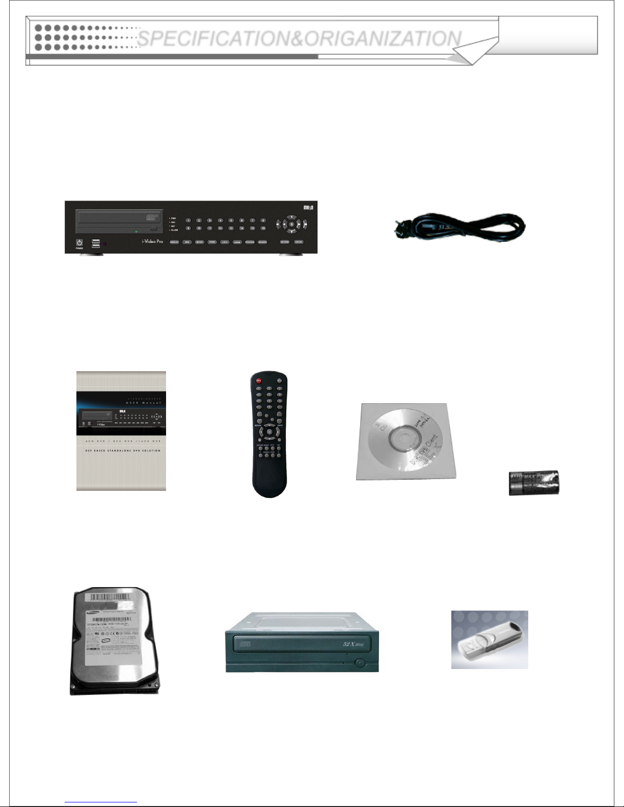
Product Contents List
Please confirm that all product contents are present when open the package.
① Basic Contents
Remote ControllerInstruction Manual Remote Agent
Installation CD
AAA Battery x 2
AC Power Cable
② Optional Contents
Internal Hard Disk Drive
Internal CD-RW/DVD-RW Drive USB Thumb Drive
SPECIFICATION&ORIGANIZATION
Page 8
8
SPECIFICATION&ORIGANIZATION
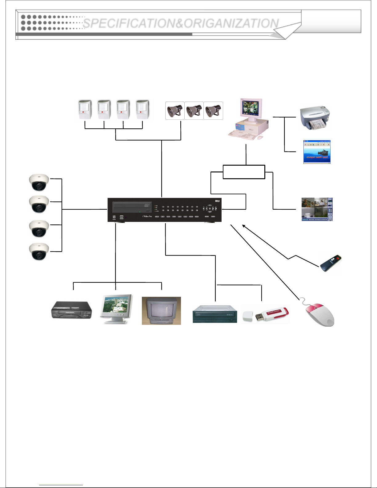
System Organization
NETWORK
Camera #1-16
Alarm Sensor #1-16 Alarm Out #1-16
VCR
VGA
Monitor
A/V Monitor
Remote Client
PC(RA & CMS)
Image Printer
Video In
Video Out
TCP/IP
Alarm Input/Out
Remote
Controller
CD/
DVDRW
Backup
AVI Backup
WEB Client
USB USB Mouse
Page 9
9
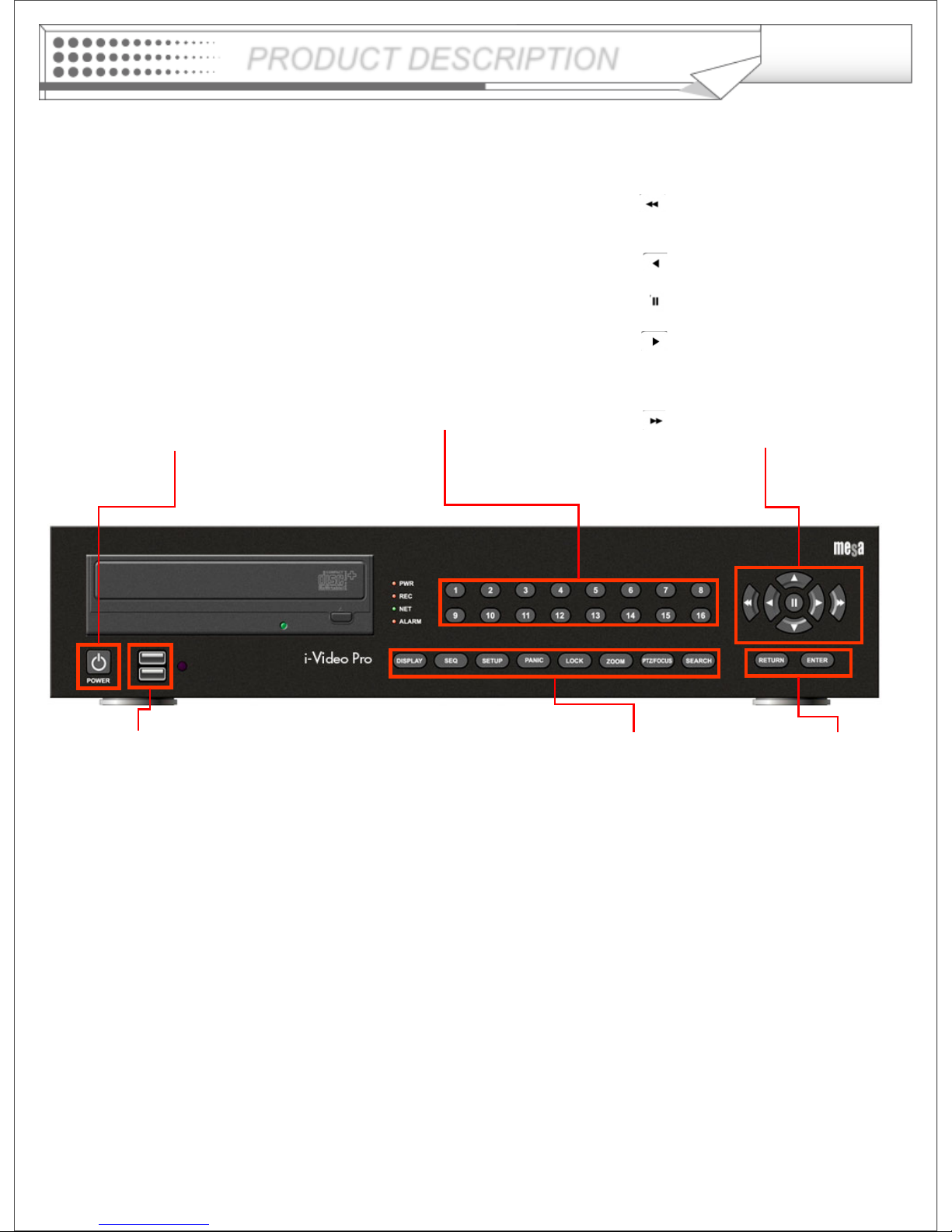
DISPLAY
Selects the various display
modes in live display and
playback
SEQ
Calls the currently defined
sequence mode
SETUP
Displays the setup menus
PANIC
Selects the panic recording
mode
LOCK
Locks the front panel buttons
ZOOM
Selects digital zoom mode in
live display
PTZ/FOCUS
Selects PTZ mode in live
display
SEARCH
Displays the search menu
USB ports
Supports a wide
variety of USB
memory stick for
archiving, system
setting backup and
firmware upgrade.
An additional USB
port is also
provided on the
rear panel
Mouse move,
Mouse right Click
and Left Click
It works same as
Mouse control
CHANNEL SELECTION
BUTTONS
Used to display individual
channels in live display and
playback ,And also used to
enter numeric
passwords for login screens
Increases the speed for
reverse playback
Reverses playback
Pauses / resumes playback
Selects forward playback
Increases the speed for
forward playback
Front Panel
PRODUCT DESCRIPTION
POWER BUTTON
Turn the power on/off
Page 10
10
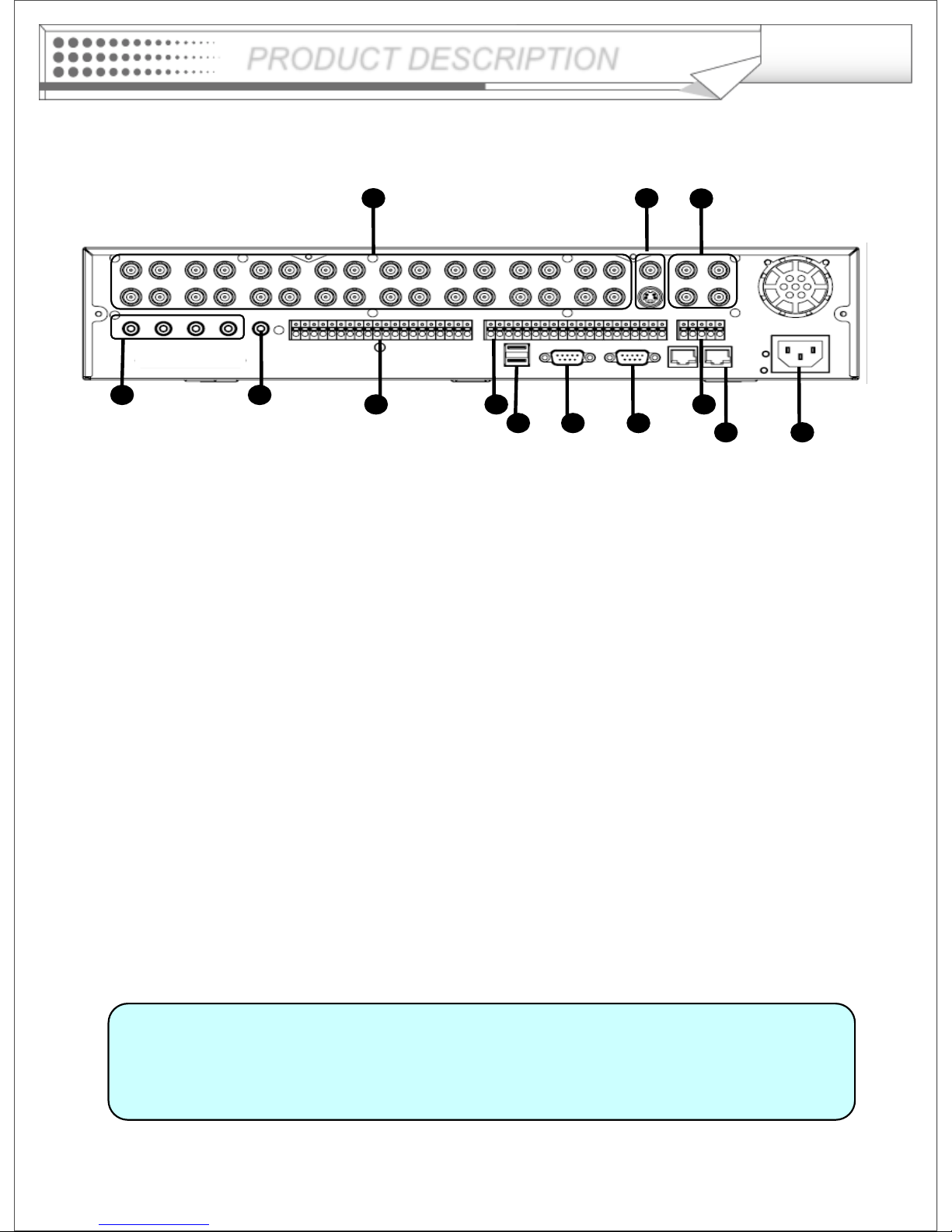
• When System Install, Please do under System Power Off Status.
• VGA monitor is main monitor. If you connect the CRT monitor through
monitor out, you can not see the menu.
Rear Panel
Tip
12
98 10
13
1 2
3
4
76
5
11
① Video IN / Loop : BNC Video Input Port, BNC Video Loop Output
② Monitor out : BNC Main Monitor Output
SVHS : Output Video by Connected SVHS.
③ Spot #1 ~ #4 : 4 x BNC Output to Individually-Sequenced Spot Monitors
④ Audio In : 4 x RCA Audio Line Input Terminal
⑤ Audio Out : RCA Audio Line Out Terminal
⑥ Alarm : 16 x Input TTL Alarm/Sensor Input Terminal
⑦ Alarm out : 16 x Digital Output Terminal
⑧ USB PORT: USB Port for backup by USB Memory Stick or USB HDD
⑨ VGA OUT : VGA Main Monitor Output
⑩ RS-232C : Serial Configuration Port for Program Debugging
⑪ RS-485 : PTZ device connection and control
⑫ RJ-45 jack : 10/100 Ethernet LAN/WAN connection (for Remote Access and Configuration)
⑬ AC Power Input
PRODUCT DESCRIPTION
Page 11
11
REMOTE CONTROLLER
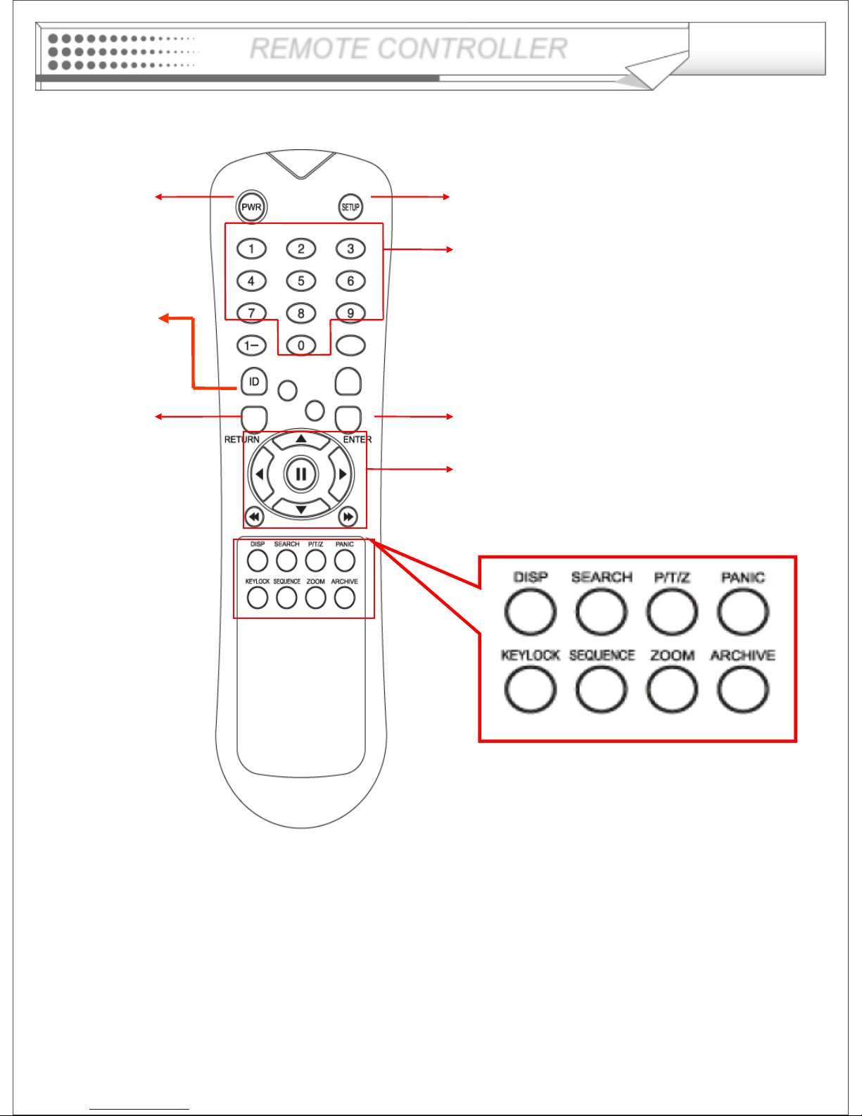
POWER
System
ON/OFF
MENU : Open System Setup Menu
RETURN
Mouse Left click
ENTER : Mouse Right Click
Channel Selection Buttons
※ If there are many DVRs on stack, each DVR must be set different ID and then Remote controller select
each ID of DVR by ID button. User can control all DVRs with one Remote controller
Navigation Buttons : Used for Playback
Control, Menu Navigation, and PTZ/Focus
Control
ID
ID Button
Select DVR ID
Page 12
12
HDD, CD/DVD-RW
CONNECTION
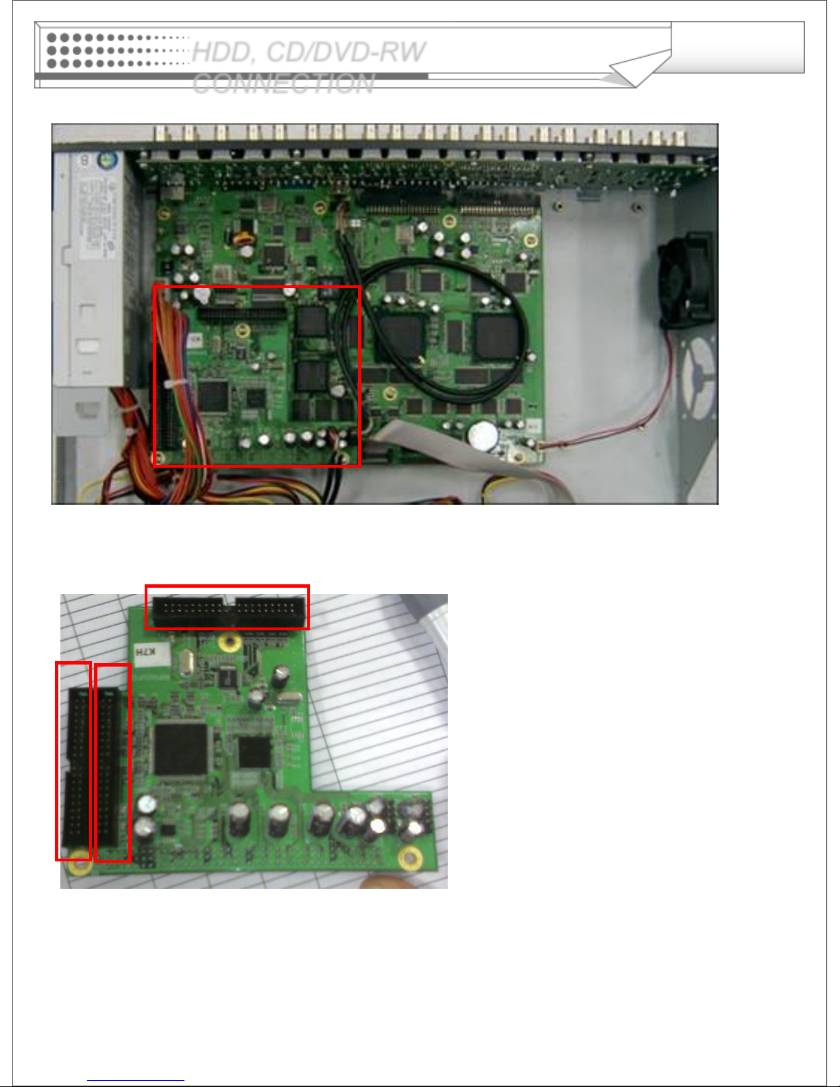
Above is the main board picture when open the top cover.
The connection board (IDE subboard) is positioned in red box
(1) is the port for the system disk (master drive), so you should install the first HDD at this port certainly. (HDD
jumper location should be “Master”).
(2) is also the port to connect additional HDD.
(3) is the port for the CD-RW or DVD-RW only. If you connect the HDD at this port, the HDD can’t be
recognized.
(1) (2)
(3)
Page 13
13
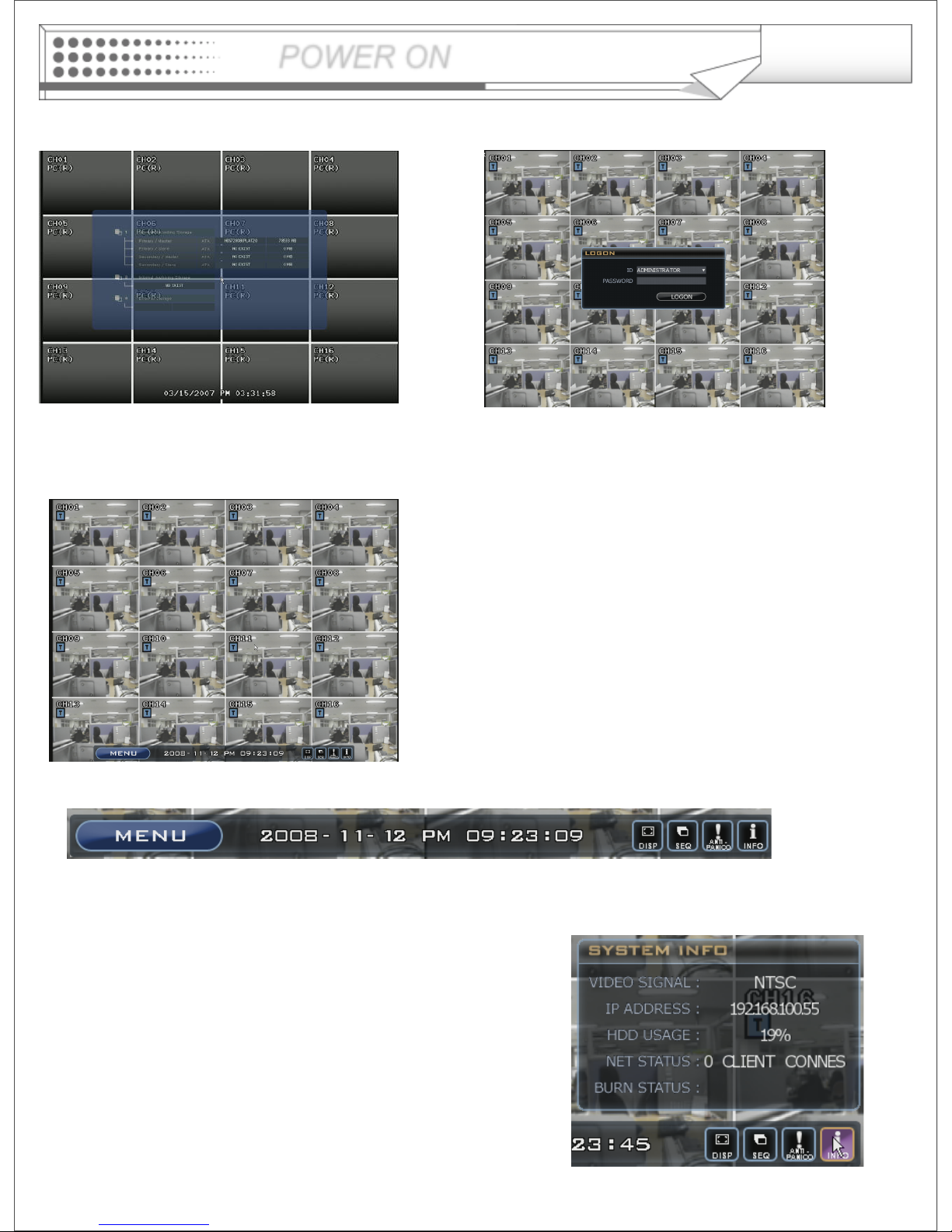
Press the power button.
DVR startup screen: detects and checks
The HDD and CD-RW/DVD-RW.
When the system completes to start up, the LOGON Box
appears and then asking to input a password.
(Default password is none. Click the LOGON button.)
DVR starts on normal operation mode and then show
display with 16channels by default.
Left top indicator on each channels show current recording
status
T: Continuous Record
M: Motion Record
A: Alarm Record
P: Panic Record
• Live System Info
1) MENU button for the system configuration
2) Date / Time information
3) DISP button for changing the display mode
4) SEQ button for the screen sequencing
5) PANIC button for the instant recording
6) INFO button for the instant system information
POWER ON
Page 14
14
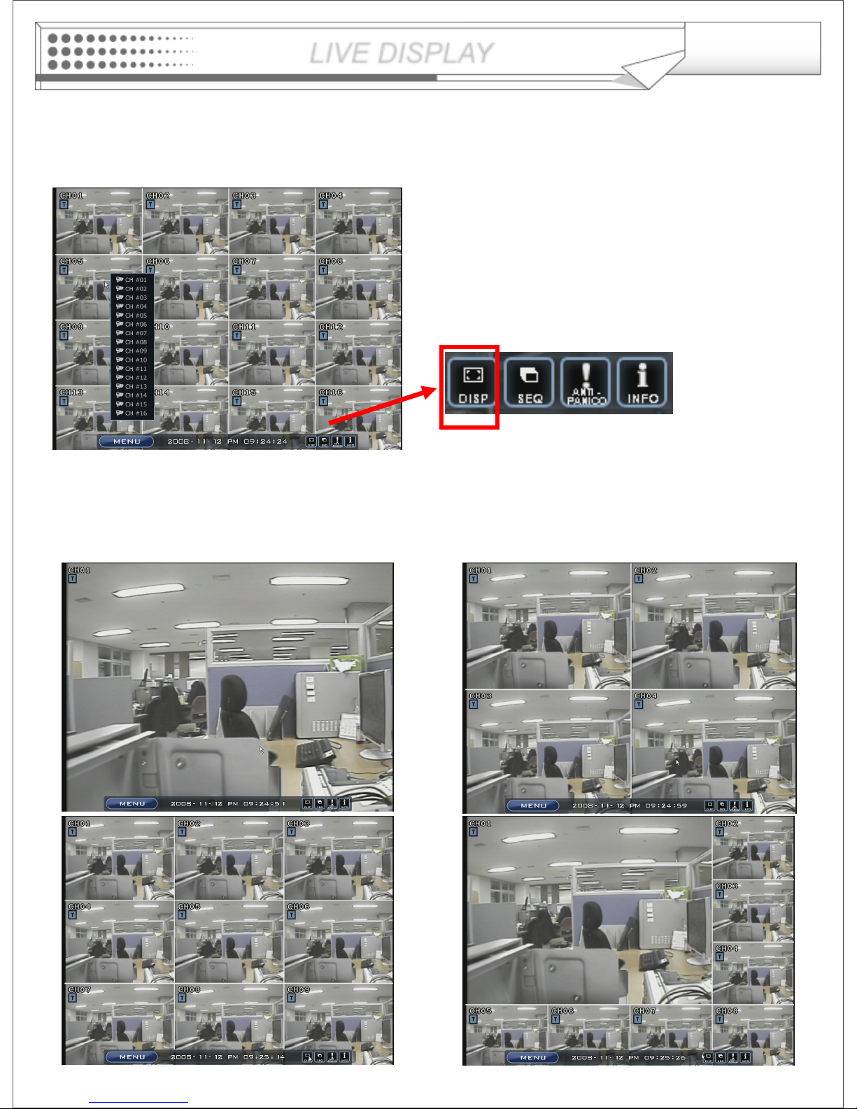
Press mouse left button on DISP icon. It will change the display mode.
• The operator can select the display mode between 5 different display type(1,4,8,9,16 split view).
• Right click of mouse will allow user to change the channel of camera at the position.
Configuring the Live Display
LIVE DISPLAY
Page 15
15
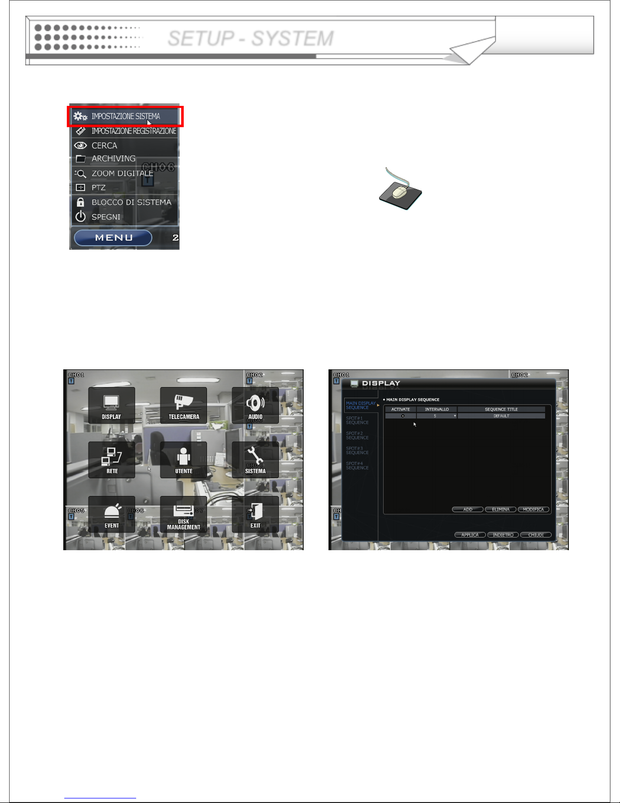
Click the MENU icon on the Live Display mode and then
Click the SYSTEM SETUP menu.
SETUP - SYSTEM
Display -> Main Display Sequence
• Main Display Sequence: Channel sequence on the main monitor.
User can configure the display mode and with ordering for sequence
- Press the ADD button.
- Select the screen template(1,4,6,8,9,16)
- Press the screen template button for changing camera number
- Press the ADD button for inserting another screen template.
- Press the screen template button for changing camera number.
- Press OK button when complete to modify.
- Select the Radio button on sequence list what you want to apply for sequence.
- Input the sequence title by virtual keyboard and the dwell time for the new list
* The Max. list Number is 16EA.
Page 16

16
Display -> Spot#1-4 Display Sequence
- Press the ADD button.
- Select Screen templates(1,4)
- Press the screen template button for changing camera number.
- Press the ADD button for inserting another screen templates.
- Press the screen template button for changing a camera number.
- Press OK button when complete to modify.
- Select the Radio button on the sequence list what you want to apply for sequence.
- Input the sequence title by virtual keyboard and dwell time for the new list
* The Max. list Number is 16EA each spot channel.
In case of advance spot, setup method is almost same as main display sequence.
How to play and stop the sequence.
Press ‘SEQ’ button, the icon’s color will be change as light green when ‘SEQ’ activating. Press SEQ button
again for stop sequence.
Additionally, press the “SEQ” button on front panel for activating sequence.
SETUP - SYSTEM
Page 17
17
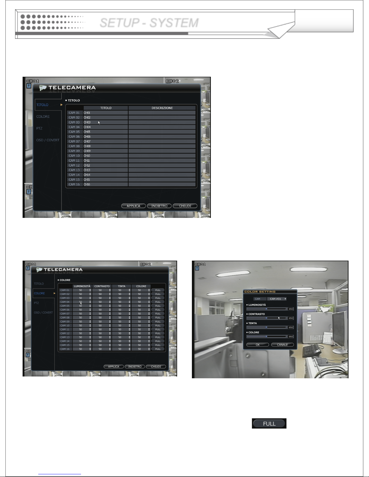
Camera -> Title
• Camera Title: Input camera title
and description by virtual keyboard.
Only English and Numeric are supported.
SETUP - SYSTEM
Camera -> Color
• Camera color setup: Select the Brightness, Contrast, Tint, Color.
The operator can configure details of color on live display when clicking the button.
Page 18
18
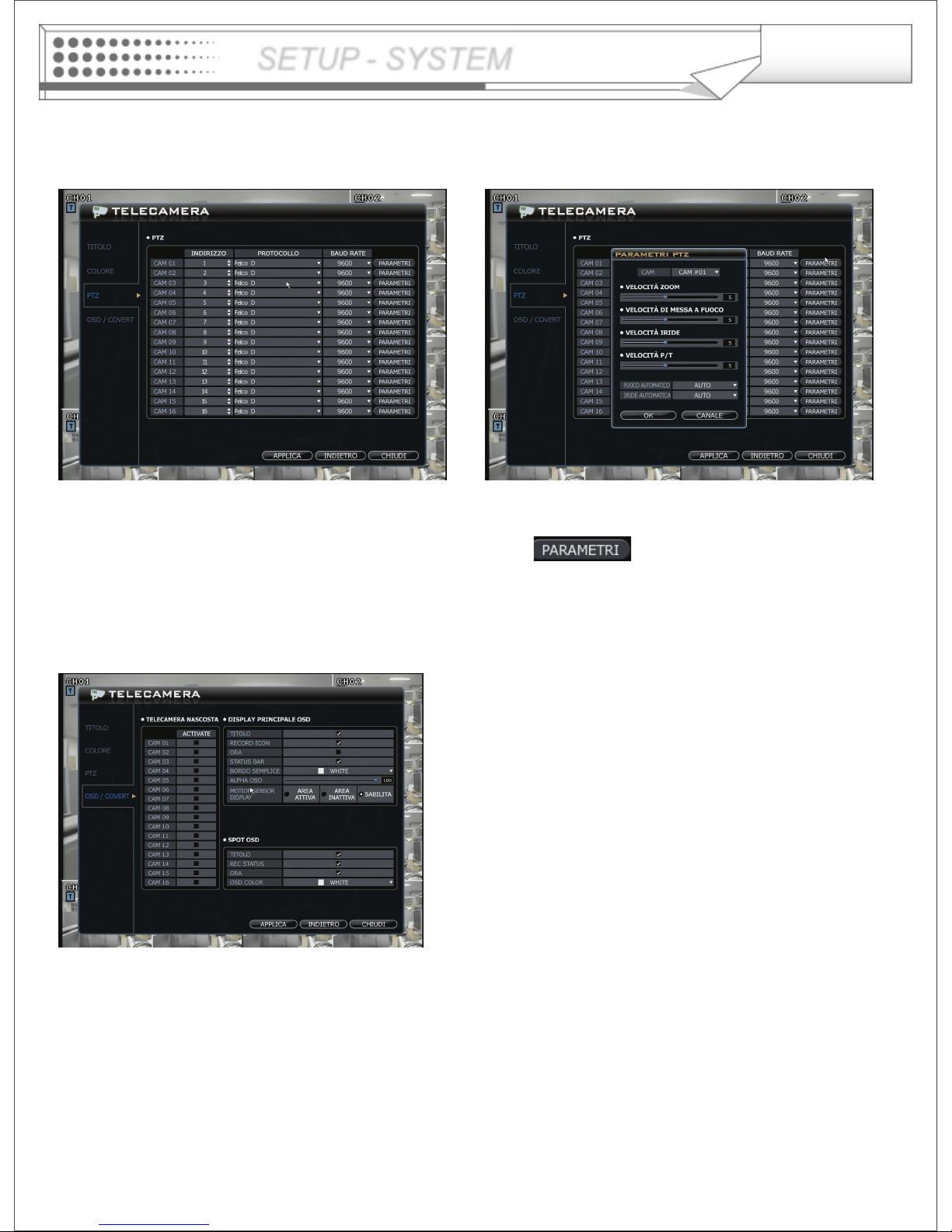
Camera -> PTZ
• Select the address, protocol and Baud rate on each camera.
The operator can configure detailed PTZ setup when click the button.
SETUP - SYSTEM
Camera -> OSD / COVERT
• Select channels for covert channel,
Configure options for main display’s OSD and spot monitor’s OSD.
Page 19
19
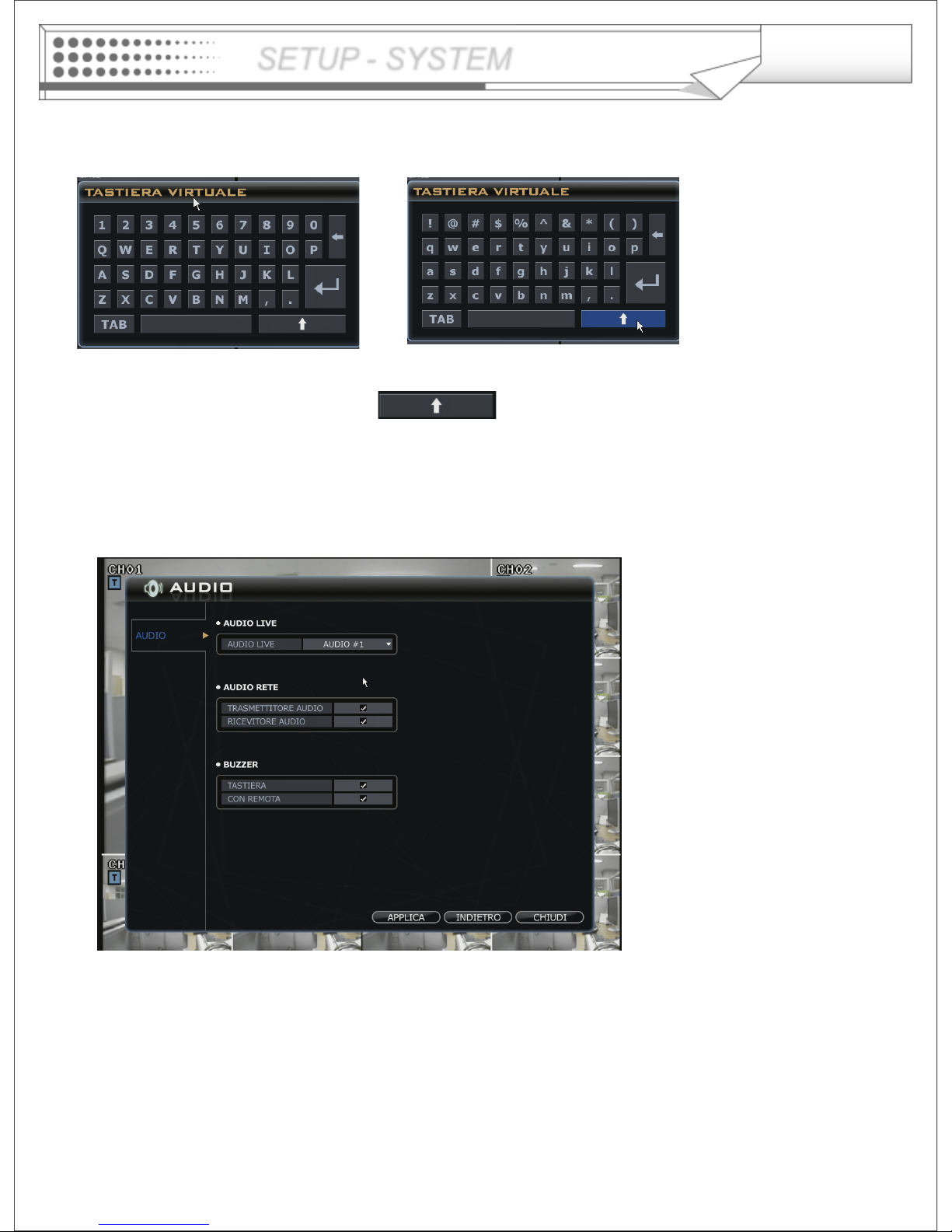
SETUP - SYSTEM
Audio
• Setup the audio configuration.
- Live Audio: Select audio channel, the selected channel's will be activated on speaker.
- Network Audio: Select audio transmitter and receiver option for communication
between DVR and Remote Software..
- Buzzer : Sound activation when press the key on front panel and Remote controller.
※ How to use virtual keyboard
Double click Mouse left button from the location that operator want to input character.
It shows virtual keyboard. Select each characters on virtual keyboard.
For using the small characters. Click the button.
Page 20
20
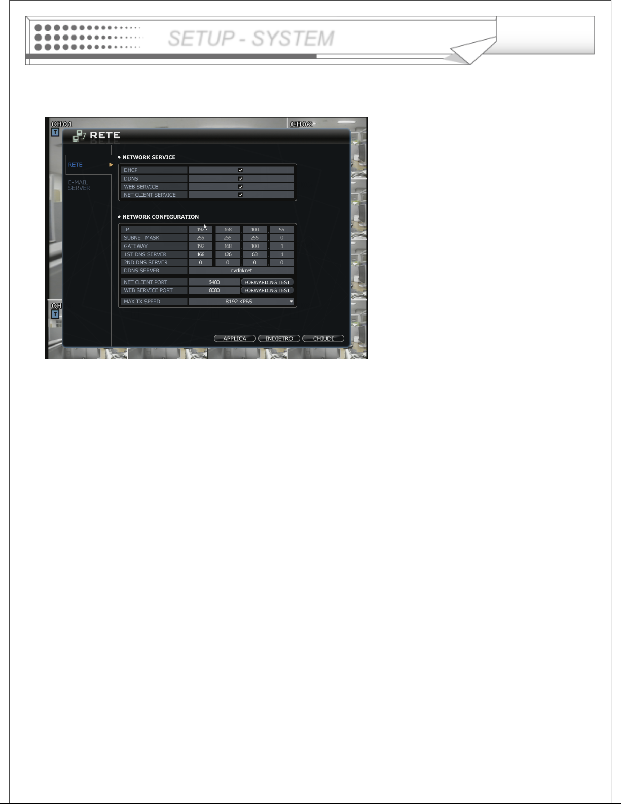
Network -> Configuration
DHCP: In case of using ‘Dynamic IP’, Check the ‘DHCP’
When click ‘APPLY’ button, DVR get the IP address automatically.
In case of using ‘Static IP’, input the IP address and other information manually.
DDNS (Dynamic DNS): This is for user who has Dynamic IP address for DVR.
※ With DDNS, no need to enter the IP address for every connection, DVR’s MAC address can be used
for DVR’s Domain name (ex. 00115f012345.dvrlink.net)
WEB SERVICE: User must check this option for connecting the DVR through Internet Explore.
NET CLIENT SERVICE: User must check this option for connecting the DVR by Remote Software.
IP, GATEWAY, SUBNET MASK and DNS SERVER: Input proper information. Asking network administrator if
user doesn’t sure the information.
DDNS Server: Input DDNS server domain name.
Net Client Port: Input net client Service Port # (Default:6400).
Web Service Port: Input the Web service port # (Default: 8080).
usage with port 8080 is http://00115f012345.dvrlink.net:8080
Max TX Speed: Setup Max Network Transmit Speed. (56k – 8192k).
♣ After any changes on the Network setup, System will prompt you to reboot system in order to save changes.)
SETUP - SYSTEM
Page 21
21
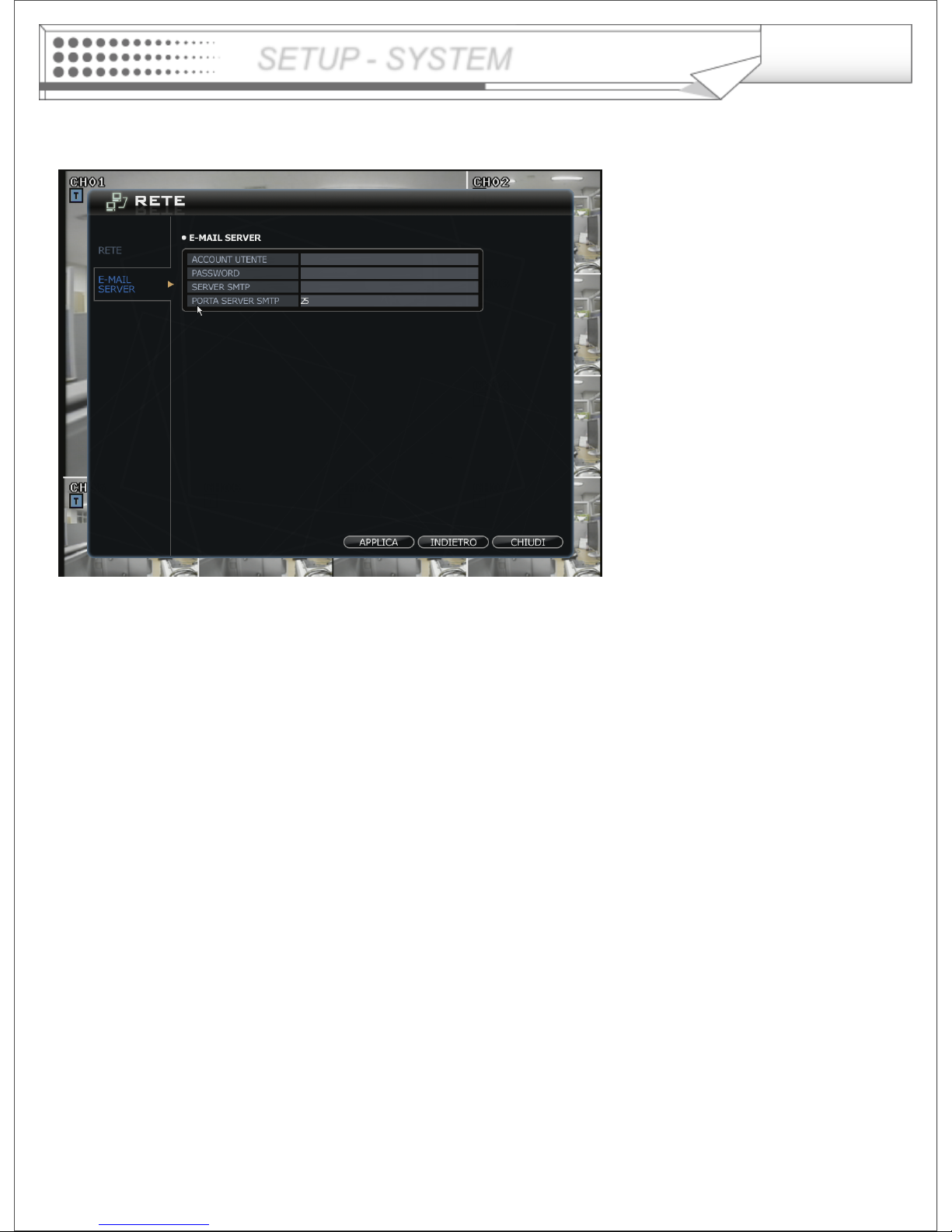
Network -> E-Mail Server
USER Account : Enter username for sending mail server.
PASSWORD : Enter password for sending mail server.
SMTP SERVER : Name of SMTP server that will be used for email notifications.
SMTP SERVER PORT : Port number for SMTP, well know port is 25.
SETUP - SYSTEM
Page 22
22
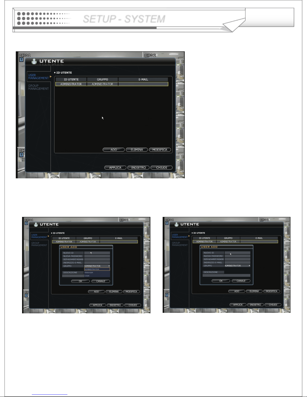
User -> USER MANAGEMENT
Default ID as ADMINISTRATOR is not allowed to delete for future maintenance.
Press ADD icon for creating new user.
Input ID and Password for new user.
Input E-mail address for receiving email notification.
Select group properly for accessing DVR.
Input description for more information about user.
Press ‘OK’ button and then ‘Apply’ button step by step.
SETUP - SYSTEM
Page 23
23
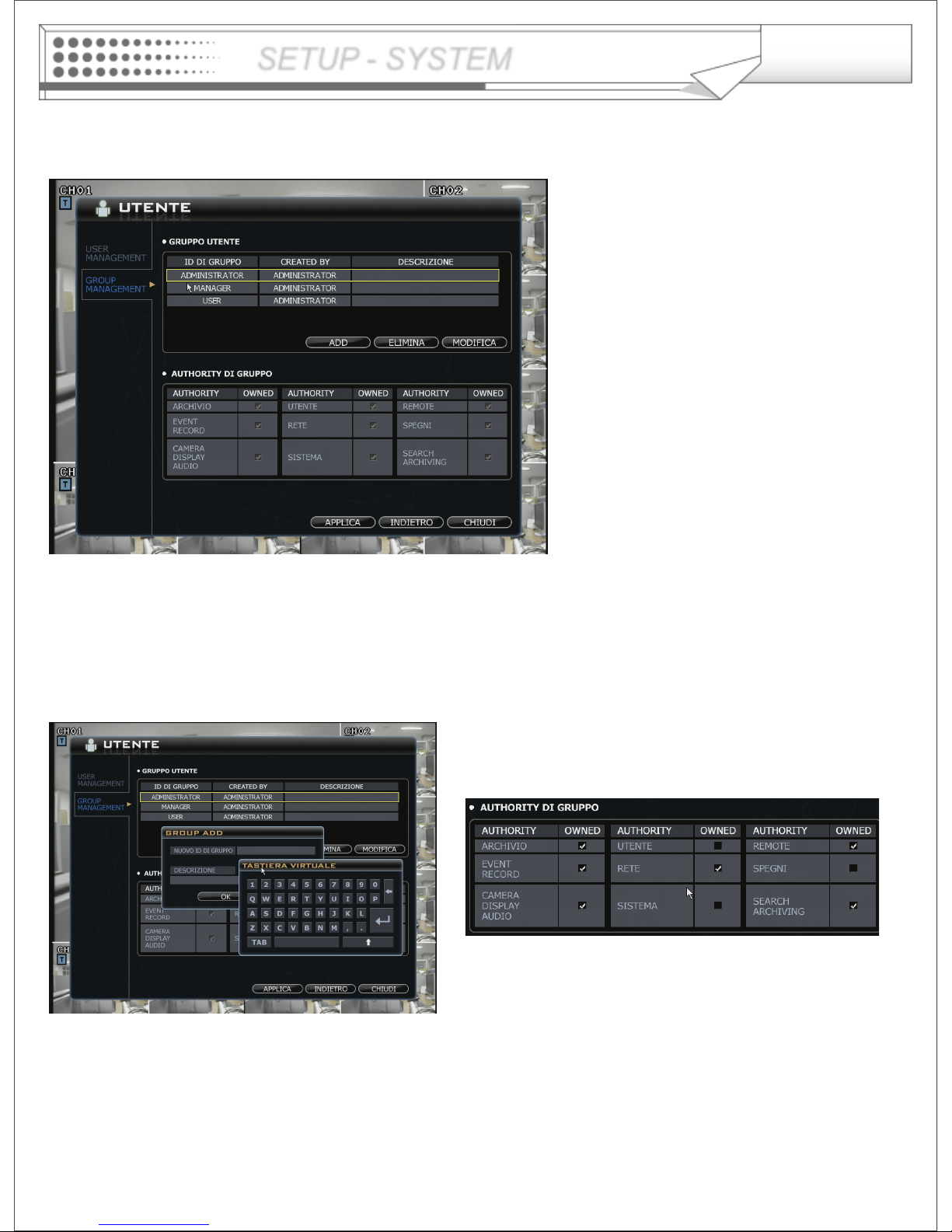
User -> Group Management
Default user group (administrator, manager, user) can not be deleted.
After selecting “ADD” button, the operator can make the new user group with new authority.
When press “ ADD” button, it shows “GROUP ADD” screen.
It shows virtual keyboard with mouse double click in order to input characters.
Press “OK button when complete to input the new group ID and description.
Then select the New group ID. (with yellow square).
Select proper authorities for new group and then click “APPLY” button.
SETUP - SYSTEM
Page 24
24
SETUP - SYSTEM
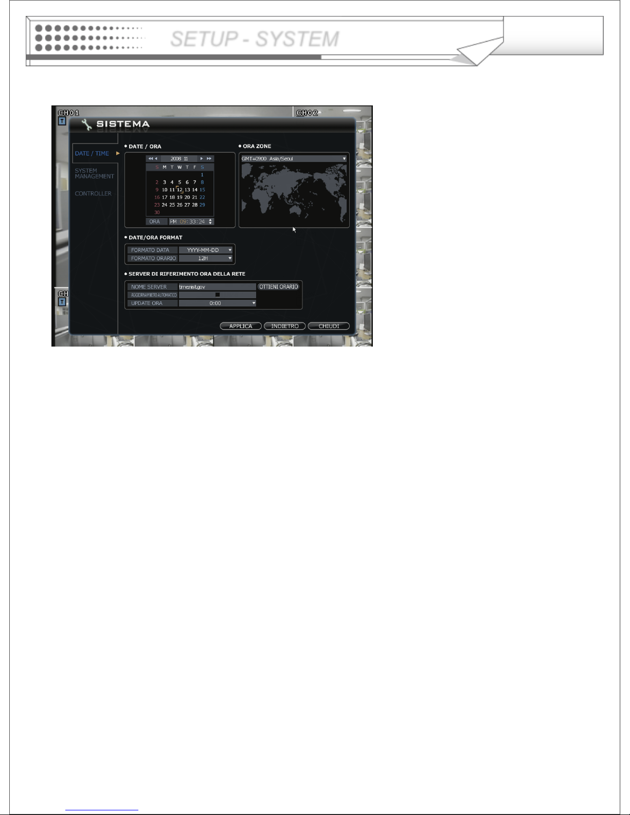
System -> Date/Time
- Date/ Time: Current DVR’s Date and Time. The operator can edit time setting manually.
- Timezone: Select the Time zone for synchronization with NTP server.
- Date and Time format: The operator can change the format of date and time.
- Network Time server: Input the network time server’s domain name for getting the time automatically.
Auto update and Time: DVR can get the time information automatically with assigned time duration in case of
connecting network.
Page 25
25
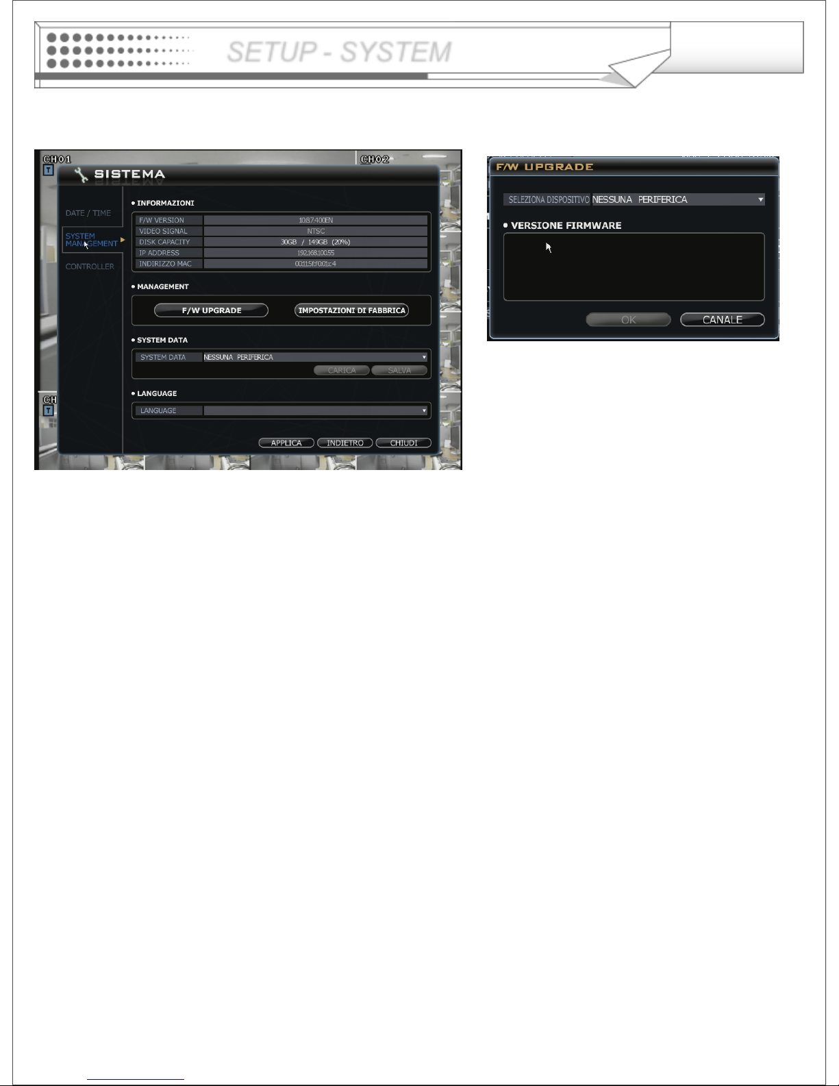
System -> System management
- Firmware Upgrade
Operator can update the F/W by USB device or CD/DVD.
After copying the F/W into USB or CD/DVD, connect it into the DVR.
Press the F/W upgrade button then they will show above screen.
After selecting proper F/W from list, select the “OK” button.
When finish the upgrade, DVR will re-boot automatically.
- Factory Default : System will be initialized (not erasing recording data) .
- System Data
Save: Current configuration will be saved into USB and other device.
Load: The configuration that saved from other DVR will be loaded and applied on current DVR.
- Select Language
Operator can select language.
Language may be different on each system options.
SETUP - SYSTEM
Page 26
26
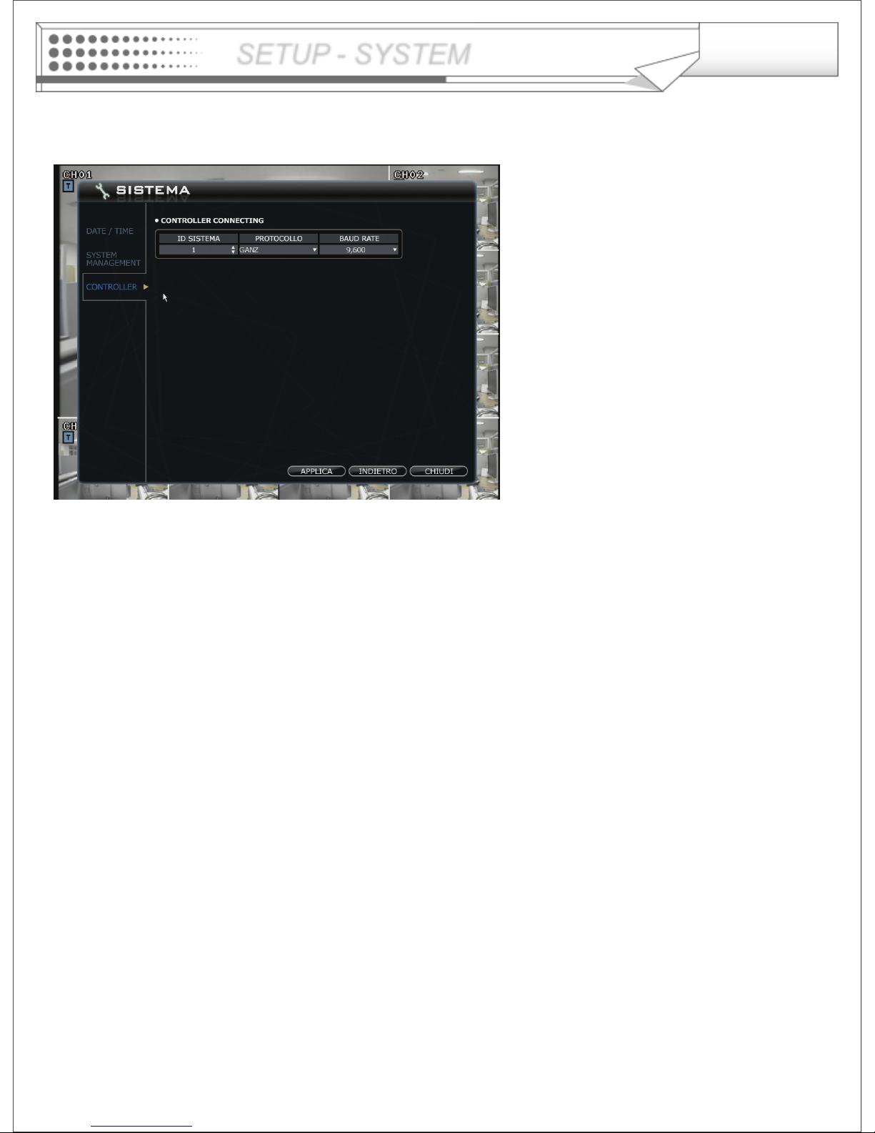
System -> Controller
Controller connecting
- Setup for keyboard joystick controller.
- Select the System ID, Protocol and
Baud rate.
- Controller must be connected by
RS485 port
- Controller works same as mouse
operation (control mouse pointer)
SETUP - SYSTEM
Page 27

27
Event -> Storage
• File system Event
- Disk Full - Alarm activation On/Off, when disk is full for recording.
• Smart Event
- Smart Warning- Alarm activation On/Off, when the system detects bad sector of HDD.
- Smart Check Period - Select from 1 hour to 24 hour for bad sector check up period time.
SETUP - SYSTEM
Event -> Alarm In
Select the Activation, Normal State (High/Low-It is related with sensor type) and input description.
Page 28

28
Event -> Motion Detection
Select the Motion Detection Activation,Sensitivity(1~10) and Motion Area.
SETUP - SYSTEM
Operator can select motion areas from above screen when click the button.
After selecting the motion areas with mouse drag, click the mouse right button, Then it shows pop-up menu
that relates with selection type.
Page 29

29
Event -> User Defined
Operator can create User Defined Event as a combination of events.
Operator can setup how it works when more than two events occur at the same time (Mixing condition
is “AND” not “OR”)
To setup detail configuration, press “EDIT” button.
Select sensor, motion, Video loss events.
After complete to configuration, action type can be set up at alarm out.
SETUP - SYSTEM
Page 30

30
Event -> Alarm Out
-Linked Event: Select an event that want
to assign alarm out channel
for action.
(Alarm, Motion, Videoloss
and User defined)
- Select Activation on/off.
- Normal status: Select the operation type.
(High / Low)
- Dwell Type: Latched/Transparent
Time: 5- 300 second for Latched
mode or until key strike
*Latched means that makes alarm when
event occur but continue for defined
duration.
*Transparent means that makes alarm
during alarm detects and lasting till end
detection.
SETUP - SYSTEM
Event -> Buzzer
: When the selected event happens, activate buzzer on/off.
-Selecting the event (Alarm, motion, Videoloss, User Defined Event) that want to make a buzzer,
select the activation on/off.
- Dwell Type: Latched/Transparent
Time: 5- 300 second for Latched Mode or until key strike
*Latched means that makes alarm when event occur but continue for defined duration.
*Transparent means that makes alarm during alarm detects and lasting till end detection.
Page 31

31
: When the selected event happens, it notifies the event through E-mail.
- Press ADD button.
- Select User ID who need to be notified events through email.
- Select the Activation on/off.
- Select Sensor, Videoloss, Motion, Storage(Smart alarm, HDD full) and user defined event).
- Input the memo.
Event -> E-mail Notification
SETUP - SYSTEM
Event -> Video Popup
: When happen the selected event, screen pop-up at the designated monitor.
- Press ADD button.
- Select the event (Alarm, motion, User Defined Event) that want to pop-up, select the activation on/off.
- Assign the camera’s channel that want to pop-up on each Monitor.
- Assign the pop-up dwell time.
Page 32

32
Event -> Remote Client Notification
: When the selected event happen, it notify the event to Remote client.
- Press ADD buttons.
- Select User ID.
- Select the Activation on/off.
- Select Sensor, Videoloss, Motion, Storage(Smart alarm, HDD full) and user defined event).
- Input the memo.
SETUP - SYSTEM
Page 33

33
Disk Management
- Operation mode: Select overwrite / write once mode (no overwrite) for recording.
- Internal recording: It shows the internal HDD recording information that installed into system.
- Format : When click the “START” button, all data will be formatted
- Internal archiving: It shows the internal archiving information that installed
SETUP - SYSTEM
Page 34

34
Click the Menu icon on the Live Display screen and then
Click the Record setup
Pre / Post Recording
SETUP - RECORD
-Pre-Event Recording Time: When the DVR is not in continuous recording mode, this setting determines the
amount of footage that is always recorded before an event occurs. (motion
detection, alarm input etc.)
- Post- Event Recording Time : When the DVR is not in continuous recording mode, this setting determines the
amount of footage that is always recorded after an event occurs. (motion
detection, alarm input etc.)
Page 35

35
Normal Record
-Drag the time that want
to setup by mouse.
In case of different setup
by times, the color will be
different.
In case of recording setup, the operator should setup as 3 divided parts.
- Select the Resolution.
- Select the Frame Rate
- Select the Quality. (low, standard, high, highest)
SETUP - RECORD
DAY OF WEEK :
Select ALL to apply the
same recording parameter
for everyday, otherwise
select each date.
Page 36

36
Schedule
The operator can select the recording type (Timer, Motion, Alarm, Alarm or Motion and Record off)
Drag the section that want to select and then click the mouse right button.
Then recording option will be appeared. The operator can select the recording option each time and channel.
SETUP - RECORD
Page 37

37
Intensive Record
In case of this record, record will be centralized at a channel that event is happened as event priority.
Parameter
-Drag the time line that want
to setup by mouse.
In case of setup
differently each time, the
color will be different.
The setup is same with normal recording setup.
It records as setup under normal condition. But when happening the event on channel, the Recording setup
of the channel that event is happened will be changed as D1, 30 FPS automatically.
If happening the event from some channels at the same time, it will share the max. Recording rate properly.
- Select the Resolution.
- Select the Frame Rate
- Select the Quality. (low, standard, high, highest)
- In case of Audio setup, it is assigned at Nr.1,2,3,4 Channel basically.
(It can not be changed)
- Select the Intensive recording condition with Alarm, Motion and User defined event.
- In case of weekly, it is almost same with daily setup. It can be setup each date.
SETUP - RECORD
Page 38

38
Schedule
The operator can select the record on/ off each time, channel.
Drag the section that want to select and then click the mouse right button.
Then the recording option will be appeared. The operator can select the recording on/off each time and channel.
SETUP - RECORD
Page 39

39
Panic Record
When user press the panic button or system detects the panic alarm, recording condition will be changed as
panic record setup.
In case of recording setup, the operator should setup as 3 divided parts.
The default setup is CIF, 30FPS.
Setup method is same with normal record setup.
- Select the Resolution.
- Select the Frame Rate
- Select the Quality. (low, standard, high, highest)
SETUP - RECORD
Page 40

40
Click the MENU icon
on the Live Display
screen and Click the
SEARCH button.
The operator can search the recorded data as normal, panorama1, panorama2 and smart search mode
Normal Search
(A)
(B)
(C)
(D)
(E)
Select the MENU icon and press the SEARCH button.
Logon window will be display and input a password.
(A) It shows image data.
(B) Select the ‘Playback’ or ‘Log’ mode
(C) Select the Date and Time for search
(D) Control window for search.
(E) It shows the recorded data .
• Playback-> Date/time
-Select the date. In case of date that have recorded data, it
shows with color at (E).
Select the time, The operator can select the time from timer or
by drag the timeline bar form (E).
- Click the button for playback from (D),
- Playback speed is from X1 to X128 forward and backward.
SEARCH
Page 41

41
During the playback, the operator can save the image that want to save.
Input the snapshot tag.
Select the channel.
Select the screen.
Input the Memo.
For saving the image, click the “reserve” button.
(The operator can check the saved image from
backup Date Management of backup menu).
START BURNING: snapshot image can be
burned into USB device or
CD/DVD-RW.
E-mail: snapshot image can be sent by E-mail.
During the playback, the operator can save the data as AVI files about period that want to save.
Input the archiving tag.
Select the channel,
Select log, text. rec index table
Input the Memo.
Click the “start” button.
Then ‘ARCH.START’ button will be changed ‘ARCH.STOP’.
(For using this function, it should work the playback
certainly. If not, it can not save AVI file).
Then it shows as left screen.
For recording continuously, click the “continue” button.
If want to stop, click the “Finish” button.
SEARCH
Page 42

42
It shows as left screen with backup data information.
How to burning and reserve is same with how to save the
snapshot.
(The operator can check the saved image from backup
Date Management of backup menu).
Full Screen : Click the button for full screen from (D). Then it shows as below screen.
For returning, move the mouse icon to the
bottom of screen.
Control panel with EXIT icon will be appleared.
Click the “EXIT” button for return original
screen.
The operator can control the playback speed
with control panel on full screen playback
mode.
SEARCH
Page 43

43
Playback display
: Click the button for changing the playback display from (D).
The operator can select the playback display mode.
• Playback -> Live View
Select the LIVE VIEW mode.
Then it shows current live display
instead of calendar.
You can see the live display and
playback display at the same time.
Live display
SEARCH
Page 44

44
• Playback-> Log
Click the LOG tap.
Then it shows as left screen.
Select the date that want to see the log
from calendar.
Select the event section that want to see.
Click to start.
Click the button for viewing timeline.
Select the log.
For playing the recording data with log, double click the log on the list.
Click same button again for returning original screen.
The option that want to search each channel can
be selected.
Page Down, Page Up, Sart of log, End of log for ordering.
SEARCH
Page 45

45
Panorama1 Search
- The operator can search the data as frame by frame.
• Select the channel.
• Select the date.
• Select the time.
• The operator can select the time from timer or by drag the timeline bar.
SEARCH
Page 46

46
Panorama2 Search
- The operator can search with divided screens in time ranges.
The operator can select the playback starting point by Drag and drop Timeline
bar.
Channel selection
Snapshot backup
Start time selection
Selection of Total time range
SEARCH
Page 47

47
Smart Search
-The operator can search by Museum search
or Motion search.
- Select the camera.
SEARCH
- Select the search method. (Museum or Motion)
- Museum search
This search indicates or generates event (consistent/inconsistency) when search is compare with the starting
image and the image continuous to occur more than Designated Time on the Designated Accuracy of the
Selected Area.
For example, assumption that a certain object got lost on the museum. Then search the point from before it got
lost to, when the object was located (select area ß). Thus, the huge change (accuracy of designated ß) could be
grasped.
-Motion search
It is a search method to indicate or generate event when the motion occurs more than Designated Time on
the Designated Accuracy of the Selected Area.
For example, to detect the motion of appropriate location (select area ß) of the image. Set the accuracy and
interval (designated time ß), to detect the event. Next start search for the event to occur according to the
assigned time interval when there is motion.
- Select the time. (From and To).
- Select the sensitivity and check interval (sec).
- Prev. button: Playback the image of previous log by based on current time.
- Next. Button: Playback the image of next log by based on current time.
- Select the area that want to search by
mouse drag.
Page 48

48
• Select the MENU icon and press the ARCHIVING menu.
• Logon window shows and input a password. It shows the backup menu.
• Input the TAG NAME and check if want to backup the LOG, TEXT and REC INDEX TABLE information.
• Select the Start time and End time with timer or timeline bar.
• Click the QUERY button. Then it shows backup data information at the ARCHIVING INFORMATION.
Click the right mouse
button on the Live Display
screen and Click the
ARCHIVING menu.
Press Burn button.
Then it shows the BURN window. Select the
device (CD/DVD,USB)
Foreground : During backup, the operator can not
control the other functions.
Background: During backup, the operator can
control the other function. It hide BURN window
behind of main screen.
Archiving
ARCHIVING
Page 49

49
Reserved Data Management
• The operator can see the saved snapshot images and AVI files which are from backup and search menu.
ARCHIVING
Select the INFORMATION.
It shows the AVI ARCIVING DATA INFORMATION window.
Page 50

50
Right click mouse button on the Live Display screen and
Click the Channel at the position.
CH SELECTION
CH SELECTION
The operator can select the 16 CAM mode with clicking above icon.
Page 51

51
Click the MENU icon on the Live
Display screen and Click the PTZ
menu.
• PTZ control panel appears like above.
1) Select the camera.
2) Control the camera direction.
3) Press this button. The operator can control the
PTZ detailed configuration with pop-up screen.
4) Control the Zoom, Focus, Iris.
5) Assign the Preset.
After moving the location, Select the number and press the
SET button.
Camera will move as assigned location when pressing the PLAY
button after selecting the number .
6) Assign the Pattern.
After selecting the number, click the PLAY button.
PTZ
Pattern Mode
- SEQUENCE PATTERN
Set preset position. [Move to any position by direction keys and click the [SET] button.
Select [SEQUENCE] in PATTERN MODE.
To make start position, click the [SET] button in PATTERN. ([SET] button is activated.)
Select preset Number in PRESET and click the [PLAY] button. (Have to select more than two preset)
ex) select preset No 1 and click the play button then select preset No 2 and click the play button.
To make stop position, click the [SET] button in PATTERN. ([SET] button is not activated.)
To run, click the [PLAY] button in PATTERN.
-CRUISE PATTERN
Select [CRUISE] in PATTREN MODE.
To make start position, click the [SET] button in PATTERN.([SET] button is activated.)
Click the direction key by manual.
To make stop position, click the [SET] button again in PATTERN ([SET] button is not activated.).
To run, click the [PLAY] button in PATTERN.
PTZ
Page 52

52
Click MENU icon on the Live Display screen and Click the DIGITIAL ZOOM.
Click button for returning to the live display.
Right click of mouse button for changing the channel. Then it shows the channel list.
Select the channel that want to change.
Location can be controlled by Mouse drag and Zoom in/out can be controlled by Mouse wheel.
DIGITAL ZOOM
DIGITAL ZOOM
Page 53

53
KEY LOCK
An operator with ADMIN rights can choose to lock the DVR front panel to prevent any un authorized control.
Press the KEY LOCK button, All buttons are now disabled.
To unlock, press the KEY LOCK button again.
Click the MENU icon on the Live Display screen
and Click the KEY LOCK menu.
Click the MENU icon on the Live
Display screen and Click the KEY
LOCK menu.
KEY LOCK
Page 54

54
PANIC REC
Panic recording will override all standard recording settings to provide, by default, continuous recording on
all channels.
Press the PANIC icon. The right top of the display shows a red square with P to indicate that the DVR is
in panic recording mode.
Press the PANIC icon again to return to normal cording mode.
Click PANIC icon on the Live Display screen.
PANIC REC
Page 55

55
SHUTDOWN
SHUT DOWN
To shutdown, user should enter the ID and password.
Click the SHUTDOWN menu.
Page 56

56
System Requirement
REMOTE SW INSTALLATION
① Main Board (CPU): Pentium-500(Minimum), Pentium 4 recommend
② OS: Higher than Windows 2000,DirectX 7.0A
③ Memory (RAM): More than 128 M
④ VGA: Graphic card that support the DIRECT-X ※IMM4 Codec (When Playback Backup File)
① Open CD-ROM Drive and Run the RemoteSW’ package. then Appear Setup Menu.
② Close All Running Software and Press Next to Move Next Step.
③ Showing Progress of Copy of Files.
④ Finish DvrRemoteAgent Program Installation.
Page 57

57
Introduction
① Main Display : Shows single or multi-channel view of cameras connected to the DVR.
② Camera Selection Buttons : Indicates Camera #; click button to display a selected camera.
③ Minimize / Exit : Minimize DVR Client Window (to taskbar) or Exit Remote Agent.
④ Date/Time Display : Shows current DVR System Date/Time
⑤ SEARCH : Enter Search Mode to Search and Playback Recorded Video
SETUP : Set up properties of Remote Agent, including the list of DVR units to connect to.
CONFIG : Allows Remote Configuration of a connected DVR unit.
⑥ DVR Selection : Choose a DVR to connect to with the Remote Agent.
⑦ Connect : Connect to selected DVR.
Disconnect : Disconnect from selected DVR.
⑧ Screen Division Selection : Change Screen Division Mode (1/4/9/16/36,64 view, sequence, full screen)
Sequence/Manual Switch/Full screen
⑨ Begin Saving to AVI file : Begin Saving Live or Playback Images to the local PC in AVI format.
⑩ Event Log Viewer : Display Current Event Log & Jump to Event for Playback.
⑪ PTZ Control Button : Control Camera Pan, Tilt, Zoom, & Focus (for supported PTZ devices only)
⑫ Audio Button and Alarm : Control Bi-Directional Audio, Mute, and Toggle Alarm (On/Off).
⑬ Quit : Exit Remote Agent.
⑭ Connection Status: Indicates the Network Status of a connected DVR.
③
⑤
④
⑥
⑦
⑧
⑪
⑨
⑩
⑫
①
⑭
⑬
REMOTE SW INSTALLATION
Page 58

58
Local Setup
①
②
③
④
⑤
① Group & DVR list.
② DVR Information.
③ Camera Assign : Setup camera.
④ Option Check.(Event-system, alarm, video,
record & In/Out)
⑤ Add, modify, delete group.
Add Group
① At ‘site’ of left upper side, right click the “Add Group”. ② Input the Group name.
REMOTE SW LOCAL SETUP
Page 59

59
③ Input DVR information.(name, IP, port, ID, PW) ④ Set camera position, check option and press ‘ADD’.
⑤ New DVR list is shown on the left upper side.
Configuration
① Video OSD : Select screen information. (title, name, date, time)
② Video output : Select video output method.
- Overlay Mixer : Output without passing through CPU.
- Video Renderer : Output through CPU.
- GDI : When you cannot see video by upper 2 way, use this way.
③ Video mode
- Screen switching interval : During the monitoring, select screen rotation interval time(2~300sec.)
- Alarm pop-up : Pop-up time of alarm happened channel on (2~60sec.) /off.
④ Saving Directory : Designate remote PC backup image saving folder.
REMOTE SW LOCAL SETUP
Page 60

60
• Select I/D to Connect Server.
• I/D can be Add, Change, and Delete at Setup.
• 1*1 View : Showing One (1) Video which User Selected.
(Selection Video by Camera Selection Button)
• 4*4 View : 4 Screen Division Mode.
• 9*9 View : 9 Screen Division Mode.
• 16*16 View : 16 Screen Division Mode
• 32*32 View : 32 Screen Division Mode
• 64*64 View : 64 Screen Division Mode
• Auto switch : Screen Mode Showing One by One (Same at division mode)
• Manual switch : Screen Mode Showing One by One by click manually.
• Full Screen View : Present Video Move to Full Screen Mode.
Mouse Double Click when Return Previous.
*Mouse Double Click Make the Same Function as Full Screen.
TIP ※ Multi DVR Client 4EA DVRs can be control the live view, search the data, backup data and
setup about each channel at the same time.
Selection Network ID
Screen Division Selection
• P/T/Z Controller : Camera P/T/Z
Control by Direction Keys
• FOCUS/ZOOM Select Button :
Focus or Zoom Control by +,- Button
• +,- Control Button : Focus or Zoom
Control
PTZ CONTROL
REMOTE SW LOCAL SETUP
Page 61

61
AVI File Conversion
• Click AVI Conversion Button to Start AVI File Conversion.
• During AVI Conversion Showing a Message and before Click
‘Stop” Save AVI File continuously .
• ‘Press ‘Stop’ to Open Designate File Name & Saving Location,
and Save AVI File.
• Saved AVI File can Open Ordinary Moving Picture Player or
Backup Player.
• Moving Picture Player Codec Version Need Higher than Divx 5.1
& IMM4 Codec.
① Indicate Event Occurred Order No.
② Indicate Event Occurred DVR No.
③ Indicate Event Occurred Camera No.
④ Indicate Event Occurred Time & Date
⑤ Indicate Event Detail Description
⑥ After Select Event, Move Search Bar in Search Mode
⑦ Return to Search Main to Play Selected Event Image
①② ③ ④
⑤
⑥
⑦
Event Viewer
REMOTE SW LOCAL SETUP
Page 62

62
Search Function Introduce
① Search Screen Playing Selected Video.
② Search Bar Search & Indicate Camera Recording Situation by Time Bar .
③ LIVE Return to Watch Mode.
SETUP Open Setup to Change Network Setup or Option.
④ Screen Division Selection Change Playing Screen Division Mode .
⑤ SEARCH Option Backup Video or Search Event.
⑥ Camera Selection Button Select Camera at the 1*1 View .
⑦ Quick Search Find Image to Designate Date & Time.
⑧ Search Controller Control Playing Video.
③
④
⑥
⑦
⑧
②
⑤
①
REMOTE SW SEARCH
Page 63

63
Search Method
②
③
④
⑤
⑥
⑦
① Indicates the Time of Day (0 ~ 24 hours) on Search Timeline.
② Indicates Recording Mode (Blue : No Recording, Red: Recorded Images Present)
③ Search Bar : Drag bar with the mouse to search through recorded video on the timeline.
④ Indicates each individual channel on the timeline.
⑤ If there are 5 or more channels, you may scroll through the channels using the arrow buttons.
⑥ Adjust the volume of the audio playback (if audio is present in the recording).
⑦ Refresh Recording Information Window
Select Date
Search Bar will Move to
Selected Date/Time
Playback Control Buttons
(Forward Play, Stop, Reverse
Play)
Playback Speed Control
(1x ~ 64x, Forward or Backward)
Exit Remote Agent
REMOTE SW SEARCH
Page 64

64
Search Option
①Archive
②Backup
Play
⑤Log Viewer
⑥Event
Viewer
③Save Image
④Print
- Archive – Backup Image from Server to Remote PC.
• Time Range
- Enter the Starting and Ending Date/Time.
• Channel : Check each channel to include in the Archive.
• Include Audio : (check/uncheck) to include Audio in
Archive.
• Select All / Deselect All : Select/Deselect All Channels.
• Press OK to begin the Archiving process. As each AVI file is written to the PC, the system will display
status.
• When the Archiving process has completed, the newly-created AVI files will be available for viewing.
REMOTE SW SEARCH
Page 65

65
- Backup Play (DVR Player) – Transfer to DVR Player
①
②
③
⑤
④
• Backup Player can be run independently of the Remote Agent software.
Tip
① Showing Image (Possible to Only 1*1View Mode).
② Backup File Open to Play First Video.
Ex. : ch02_04131730_04131735.rec
( Backup File for # 2 ch. Apr.13, 17H30M ~17H35M )
③ Indicate total playing time.
④ Indicate Present Time & Date and Possible to Search Time & Date.
⑤ Search Controller, the Same Way of Previous Search.
REMOTE SW SEARCH
Page 66

66
- Save Image – Capture Image and Save to Local PC
• Click ‘Save Image’ Icon During Playing Video.
• Designate File name, File Type (JPG,BMP), and Location and Press Saving.
• Conversion and Saving Image from Remote Viewer.
- Print Image – Present Image Capture and Print Out Image
• During Play Video, Click ‘Print Image’ .
• After Selecting Printer, Start Image Printing.
• Print Out Remote Viewer Image.
REMOTE SW SEARCH
Page 67

67
①
②
③ ④ ⑤ ⑥
⑦
⑧
⑨
⑩ ⑪
- Log Viewer – Find Video from the DVR Event Log.
① Select Starting Date/Time and Ending Date/Time from which to search for Event Log events.
- Press Search Button to Search and View Search Results.
② Choose the DVR to Search.
③ Indicates the order in which events in the Event Log occurred.
④ Indicates the Camera # on which the event occurred.
⑤ Indicates the Date/Time when the event occurred.
⑥ Description of the event.
⑦ Move to Previous Page of Search results.
⑧ Move to Next Page of Search results.
⑨ Select a page of Search results to view.
⑩ Go to Selected Event on the Search Timeline.
⑪ Return to Search Window.
REMOTE SW SEARCH
Page 68

68
① ② ③ ④
⑤
⑥
- Event Viewer - Showing Present Event in Server & Find Image
① Indicates the order in which events occurred.
② Indicates the DVR # on which an event occurred.
③ Indicates the Camera # on which an event occurred.
④ The Date/Time during which the event occurred.
⑤ Description of event.
⑥ Go to Selected Event on the Search Timeline.
⑦ Return to Search Window.
REMOTE SW SEARCH
Page 69

69
Select the System setup or Record
setup.
Press button and it shows left
screen.
Click the “System” icon.
Input the Password. ( Current default
password is none.
So click the “OK” w/o inputting the
password )
REMOTE SW DVR SYSTEM SETUP
Page 70

70
Camera
Title: Input the name and description after
selecting the channel with mouse.
Color: Select the Brightness, Contrast, Tint,
Color
each channel.
PTZ: Select the address, protocol, Baud rate
each channel.
Covert/OSD: Select the covert and main display,
spot OSD setup.
REMOTE SW DVR SYSTEM SETUP
Page 71

71
Alarm/Event
Sensor Event: Select the Activation, Active
State (N/C, N/O-It is related with
sensor type) and input the description.
VideoLoss Event: Select the video loss
Activation.
Motion Detection Event: Select the Motion
Detection Activation and
Sensitivity(1~10) and
Motion Area.
Select the “AREA” icon. It shows above screen.
Select the motion area by Mouse drag then choose
one of menu (select, deselect, cancel)
REMOTE SW DVR SYSTEM SETUP
Page 72

72
Disk Full: When disk full, Activation On/Off.
Storage Event
Select the user event Activation
- User Event
Click the “Edit” then it shows above screen.
The operator can make the User Defined Event with
current event’s mixing.
When happen the over two events at the same time, the
operator can setup how it work.
(Mixing condition is “AND” not “OR”)
Setup the detail configuration after entering the “Editor”
with clicking the “EDIT” button.
Select the Alarm, motion, Videoloss, Internal HDD,
External HDD, User Defined Event as user want.
After selecting it, action type can setup from Event Action
Setup.
REMOTE SW DVR SYSTEM SETUP
Page 73

73
- Event Action
* Relay out
* E-mail notification
- Setup the User ID that want to receive the each event.
-Press “ ADD” button.
- After selecting added user ID, select the each event
(Sensor(Alarm), Videoloss, Motion, Storage and User
Defined Event) and then check the Activation on /off.
- Registered User can be deleted by Pressing the
‘DELETE” button.
- Select the event that want to assign the action.
- Select the Activation on/off.
- Active state: Select the operation type(High / Low)
- Dwell: Select the type and Action Time.
Transparent : It work from Event start time to Event end
time.
Latched : It work during selected period.
(1 ~300 second and until pressing any key)
* Remote client notification
- When happen the selected event, it notify the event to
Remote client.
- Press “ ADD” button.
- After selecting added user ID, select the each event
(Sensor(Alarm), Videoloss, Motion, Storage and User
Defined Event) and then check the Activation on /off.
- Registered User can be deleted by Pressing the
‘DELETE” button.
REMOTE SW DVR SYSTEM SETUP
Page 74

74
* Buzzer
- When happen the selected event, select buzzer on/off.
- After selecting the event(Alarm, motion, video loss,User
Defined Event) that want to buzzer, select the activation
on/off.
- Select the buzzer type (Latched, Transparent)
DISPLAY
- Screen Template
Select the screen division(typeA,B,C,D,E)
Double Click at the location that operator want to change.
- Then screen template is made or changed.
- The operator can make new screen template or modify
the current screen template.
Double click the template that want to modify.
Input the name.
Select the channel from screen template.
Click the “OK”.
REMOTE SW DVR SYSTEM SETUP
Page 75

75
- Main Display Setup
- Press the ADD button or select the current list.
- Select the name and dwell time.
- Select the new list.
- Select the screen template that want to do the sequence
each channel.
- The operator can add Max.16EA screen template as
same method.
- When pressing the DELETE button after selecting the list,
list is deleted.
- The Max. list Number is 16EA.
- For selecting display, check the square.
- Spot#1~4 Sequence
In case of advance spot, how to setup is almost same
with
main display sequence.
The different thing is only one.
The screen template that can select is only two types.
(1,4 division).
- Press the ADD button or select the current list.
- Select the dwell time.
- Select the screen template that want to do the
sequence.
- The operator can add Max.16EA screen template as
same method.
- When pressing the DELETE button after selecting the
list,
list is deleted.
* The Max. list Number is 16EA each spot channel.
- How to play and stop the sequence
After clicking mouse right button from live
display, select the “SEQUENCE PLAY” or
“SEQUENCE STOP”
Additionally, press the “SEQ” button from DVR.
REMOTE SW DVR SYSTEM SETUP
Page 76

76
AUDIO
- Live Audio
Select the Live audio channel.
- Network Audio
Select the audio transmitter and receiver
USER
- User group
- User
Default user group(ADMINISTRATOR, MANAGER,
USER) can not be deleted.
After selecting “ADD” button, the operator can make the
new user group with new authority.
From below section, the operator can select each
authority.
After selecting the new group, check the authority that
want to have. Then click the “apply” button.
How to EDIT is almost same with ADD after selecting the
“EDIT” button.
The operator can add, delete or edit the new user.
When selecting the “ADD” button, it shows “add user”
screen.
After inputting the ID,PW, click the “OK”.
Then select the Group and input the E-mail address.
REMOTE SW DVR SYSTEM SETUP
Page 77

77
Input the Password.
(Current default password is non.
So click the “OK” w/o inputting the password)
Record Mode
- Select the “record mode” and “weekly/daily”.
In case of selecting the “Normal Record” from
record mode, The operator can not enter
“Intensive Record” setup.
Oppositely in case of selecting the “Intensive
Record”, The operator can not enter “Normal
Record” setup.
REMOTE SW DVR RECORD SETUP
Page 78

78
- Weekly/Daily
The operator can select the ‘Weekly” and “Daily” record setup from ‘Normal Record” and ‘Intensive Record”
setup.
So the DVR will record as daily and weekly setup configuration of “Normal and Intensive record” setup mode.
Pre-Event Recording Time: When the DVR is not in continuous recording mode, this setting determines the
amount of footage that is always recorded before an event occurs. (motion
detection, alarm input etc.)
Post- Event Recording Time : When the DVR is not in continuous recording mode, this setting determines the
amount of footage that is always recorded after an event occurs. (motion
detection, alarm input etc.)
- Panic Recording: Disable : Not use the Panic recording function
Manual: It work by pressing the Panic button from Remote controller or Front panel and
sensor. Press the Panic button again to stop the panic recording.
Auto: After starting the panic recording, Panic recording will be stopped if assigned time is
passed automatically.
- Panic Recording Time: It is related with “Auto” option of Panic recording.
- Event Link: Select the sensor channel and user defined event each channel.
REMOTE SW DVR RECORD SETUP
Page 79

79
Normal Record
- Select the Daily/Weekly.
- Select the Parameter/Schedule
- Click the “SET” icon. Then it shows above screen.
In case of recording setup, the operator should setup as 4 divided parts.
The operator can setup Max.CIF,120FPS each divided part.
- Select the Resolution.
- Select the Frame Rate
- Select the Quality. (low, standard, high, highest)
- The operator can setup other divided part as same method.
- In case of Audio setup, it is assigned at Nr.1,2,3,4 Channel basically.
(It can not be changed)
In case of weekly, it is almost same with daily setup.
It can setup each date.
- Parameter
- Drag the time that want to setup by mouse. In case of setup differently each time, the color is different
REMOTE SW DVR RECORD SETUP
Page 80

80
- Schedule
The operator can select recording type (Timer, Motion, Alarm,
User Defined, Alarm or Motion and Record off)
each time, channel.
Drag the section that want to select and then click the mouse
right button.
Then recording option will be appeared. The operator can
select the recording option each time and channel..
REMOTE SW DVR RECORD SETUP
Page 81

81
Intensive Record
- In case of this record, record will be centralized at channel that event is happened as event priority.
- Parameter
- Drag the time that want to setup by mouse. In case of setup differently each time, the color is different
The setup is same with normal recording setup.
It record as setup under normal condition. But when happening the event on channel, the Recording setup of the
channel that event is happened will be changed as D1, 30 FPS automatically.
If happening the event from some channels at the same time, it will share the max. Recording rate properly.
In case of recording setup, the operator should setup as 4 divided parts.
The operator can setup Max.CIF,120FPS each divided part.
- Select the Resolution.
- Select the Frame Rate
- Select the Quality. (low, standard, high, highest)
- The operator can setup other divided part as same method.
- In case of Audio setup, it is assigned at Nr.1,2,3,4 Channel basically.
(It can not be changed)
Select the Intensive recording condition with Alarm, Motion and User defined event.
- In case of weekly, it is almost same with daily setup. It can setup each date.
REMOTE SW DVR RECORD SETUP
Page 82

82
- Schedule
Panic Record
When pressing the panic button or detecting the panic alarm, recording condition is changed as panic record
setup.
The operator can select the record on/ off each time,
channel.
Drag the section that want to select and then click the
mouse right button.
Then recording option will be appeared. The operator can
select the recording on/off each time and channel.
In case of recording setup, the operator should setup as 4 divided parts.
The default setup is CIF, 30FPS.
Setup method is same with normal record setup.
The operator can setup Max.CIF,120FPS each divided part.
- Select the Resolution.
- Select the Frame Rate
- Select the Quality. (low, standard, high, highest)
- The operator can setup other divided part as same method.
- In case of Audio setup, it is assigned at Nr.1,2,3,4 Channel basically.
(It can not be changed)
REMOTE SW DVR RECORD SETUP
Page 83

83
WEB CLIENT SETUP
• WEB Client Connection
Input the IP Address or URL of the DVR in the Internet Explorer Address Bar.
If when user use the DDNS, input the URL with default port number (8080) like below.
http://00115FA1A4.dvrlink.net:8080
Then a dialog will appear to confirm download of an ActiveX control. Please click ‘Confirm’ or ‘Continue’.
Then click the SETUP button.
Page 84

84
WEB CLIENT SETUP
• WEB Client Connection
Click the right button of mouse on the Site in Group and click the Add Group menu like below.
Input the Group Name.
Page 85

85
WEB CLIENT SETUP
• WEB Client Connection
Click the Grout name and input the DVR information.
* Input the default Port and User ID correctly. (6400, ADMINISTRATOR with NO PASSWORD)
Then click the ADD button and OK button.
Select the site name and click the connection button then input the password. (Default : No password)
Page 86

86
WEB CLIENT SETUP
• WEB Client Connection
If the DVR information is correct, can see the connected screen like below.
 Loading...