

Meru Radio Switch RS4000
Reference Guide
Copyright © Meru Networks, Inc., 2003–2005. All rights reserved.
Other names and brands may be claimed as the property of others.
Document Number: 882-80000 Rev A


Contents
About This Guide . . . . . . . . . . . . . . . . . . . . . . . . . . . . . . xi
Audience . . . . . . . . . . . . . . . . . . . . . . . . . . . . . . . . xi
In This Guide . . . . . . . . . . . . . . . . . . . . . . . . . . . . . . xi
Other Sources of Information . . . . . . . . . . . . . . . . . . . . . . . . xi
Typographic Conventions . . . . . . . . . . . . . . . . . . . . . . . . . xii
Contacting Meru . . . . . . . . . . . . . . . . . . . . . . . . . . . . . xii
Customer Services and Support . . . . . . . . . . . . . . . . . . . . . . xii
Chapter 1
Chapter 2
Chapter 3
About the Radio Switch RS4000 . . . . . . . . . . . . . . . . . . . . . . 1
Hardware Features and Specifications . . . . . . . . . . . . . . . . . . . 2
WLAN Features and Specifications . . . . . . . . . . . . . . . . . . . . 4
Management and Monitoring . . . . . . . . . . . . . . . . . . . . . . . 4
Installing the RS4000 . . . . . . . . . . . . . . . . . . . . . . . . . . . . 5
Planning the Installation . . . . . . . . . . . . . . . . . . . . . . . . . . 5
Prerequisites and System Requirements. . . . . . . . . . . . . . . . . . . 5
Check Product Package Contents . . . . . . . . . . . . . . . . . . . . . 5
Safety Precautions . . . . . . . . . . . . . . . . . . . . . . . . . . . 6
Installation Guidelines . . . . . . . . . . . . . . . . . . . . . . . . . 7
Performing the Installation . . . . . . . . . . . . . . . . . . . . . . . . . 9
Installation Summary . . . . . . . . . . . . . . . . . . . . . . . . . . 9
Initial Configuration of the RS4000 . . . . . . . . . . . . . . . . . . . . 9
Wall Mounting the RS4000 . . . . . . . . . . . . . . . . . . . . . . . 11
Hoffman Enclosure RS4000 Installation . . . . . . . . . . . . . . . . . . 14
Power On Components . . . . . . . . . . . . . . . . . . . . . . . . . 15
Checking LED Activity . . . . . . . . . . . . . . . . . . . . . . . . . 16
Configuring the Meru RS4000 . . . . . . . . . . . . . . . . . . . . . . 19
Determine How the RS4000 Is To Be Managed . . . . . . . . . . . . . . . . . 19
Using the CLI with a Telnet/SSH Connection . . . . . . . . . . . . . . . . 19
Using SNMP . . . . . . . . . . . . . . . . . . . . . . . . . . . . . 19
Configuring of the Radio Switch with the CLI Commands . . . . . . . . . . . . . 21
Configuring the WLAN Parameters . . . . . . . . . . . . . . . . . . . . 21
Configuring an ESSID . . . . . . . . . . . . . . . . . . . . . . . . . 24
Configuring System Security . . . . . . . . . . . . . . . . . . . . . . . 24
Configuring Radio Parameters . . . . . . . . . . . . . . . . . . . . . . 24
Activating and Saving Changes . . . . . . . . . . . . . . . . . . . . . . . 25
Contents iii

Chapter 4
Appendix A
Appendix B
Managing and Monitoring the RS4000 . . . . . . . . . . . . . . . . . 27
Managing the RS4000 . . . . . . . . . . . . . . . . . . . . . . . . . . . 27
Saving the Configuration to a Remote Server . . . . . . . . . . . . . . . . 27
Upgrading the System Software . . . . . . . . . . . . . . . . . . . . . 27
Monitoring the RS4000 . . . . . . . . . . . . . . . . . . . . . . . . . . 28
Checking System Details . . . . . . . . . . . . . . . . . . . . . . . . 28
Checking Syslog Messages . . . . . . . . . . . . . . . . . . . . . . . 29
Checking Security Options . . . . . . . . . . . . . . . . . . . . . . . 30
Checking Network Settings . . . . . . . . . . . . . . . . . . . . . . . 30
Checking Wireless Statistics . . . . . . . . . . . . . . . . . . . . . . . 31
Command Reference . . . . . . . . . . . . . . . . . . . . . . . . . . . 33
MIB Definition Reference . . . . . . . . . . . . . . . . . . . . . . . . 93
RFC 1212 MIB—System Group . . . . . . . . . . . . . . . . . . . . . . . 93
RFC 1213 MIB—Interface Group . . . . . . . . . . . . . . . . . . . . . . 95
IEEE 802.11 MIB—Dot11 Counter Table (Statistics) . . . . . . . . . . . . . . 97
Meru Enterprise MIB—AP System Entry . . . . . . . . . . . . . . . . . . . 98
Meru Enterprise MIB—Network Configuration MIB. . . . . . . . . . . . . . . 99
Meru Enterprise MIB—Load Balancing MIB. . . . . . . . . . . . . . . . . . 100
Meru Enterprise MIB—Global Radius Profile Configuration MIB . . . . . . . . .100
Meru Enterprise MIB—Meru Interface Table. . . . . . . . . . . . . . . . . . 101
Meru Enterprise MIB—Trap Community Interface . . . . . . . . . . . . . . .104
Meru Enterprise MIB—SNMP Community Interface . . . . . . . . . . . . . . 104
Meru Enterprise MIB—SNMP Traps Flag . . . . . . . . . . . . . . . . . . . 105
Meru Enterprise MIB—Global Entry. . . . . . . . . . . . . . . . . . . . . 105
Meru Enterprise MIB—Syslog Table . . . . . . . . . . . . . . . . . . . . . 106
Meru Enterprise MIB—File Transfer Table . . . . . . . . . . . . . . . . . .107
Meru Enterprise MIB—Upgrade Flag. . . . . . . . . . . . . . . . . . . . .109
Meru Enterprise MIB—Upgrade Status Flag . . . . . . . . . . . . . . . . . . 109
Appendix C
Appendix D
iv Meru Radio Switch RS4000 Reference Guide
Specifications . . . . . . . . . . . . . . . . . . . . . . . . . . . . . . . 111
FCC Compliance . . . . . . . . . . . . . . . . . . . . . . . . . . . . . 111
Wireless Interface . . . . . . . . . . . . . . . . . . . . . . . . . . . . 112
Ethernet Interface . . . . . . . . . . . . . . . . . . . . . . . . . . . .112
Physical . . . . . . . . . . . . . . . . . . . . . . . . . . . . . . . . 112
Regulatory Information . . . . . . . . . . . . . . . . . . . . . . . . . 113
Federal Communications Commission (FCC) Declaration of Conformity (DoC)
and Instructions . . . . . . . . . . . . . . . . . . . . . . . . 113
Declaration of Conformity. . . . . . . . . . . . . . . . . . . . . . . .113
Instructions . . . . . . . . . . . . . . . . . . . . . . . . . . . . . 114
List of Regulatory Compliance Certifications Summary by Country . . . . . . . . . 115

Appendix E
Appendix F
Channels . . . . . . . . . . . . . . . . . . . . . . . . . . . . . . . . . . 117
Channels . . . . . . . . . . . . . . . . . . . . . . . . . . . . . . . 117
IEEE 802.11a . . . . . . . . . . . . . . . . . . . . . . . . . . . . 117
IEEE 802.11bg . . . . . . . . . . . . . . . . . . . . . . . . . . . 118
Translated Safety Warnings . . . . . . . . . . . . . . . . . . . . . . . 121
Dipole Antenna Installation Warning . . . . . . . . . . . . . . . . . . . . 122
Explosive Device Proximity Warning . . . . . . . . . . . . . . . . . . . . 123
Installation Warning . . . . . . . . . . . . . . . . . . . . . . . . . . . 124
Circuit Breaker (15A) Warning . . . . . . . . . . . . . . . . . . . . . . 125
Contents v

vi Meru Radio Switch RS4000 Reference Guide

List of Figures
Figure 1 Meru Radio Switch RS4000 .....................................................................................2
Figure 2 Bracket Attached to RS4000 ....................................................................................12
Figure 3 Antenna Mounting Bracket ......................................................................................13
Figure 4 RS4000 Top Panel ....................................................................................................15
Figure 5 RS4000 Status LEDs ................................................................................................16
List of Figures vii

viii Meru Radio Switch RS4000 Reference Guide

List of Tables
Table 1 RS4000 Hardware Features ..................................................................................... 3
Table 2 RS4000 Installation Tools........................................................................................ 8
Table 3 RS4000 LED Descriptions....................................................................................... 17
Table 4 Field Descriptions for show dot11couters ............................................................... 69
Table 5 Field Descriptions for show interfaces .................................................................... 73
Table 6 Field Descriptions for show ip................................................................................. 78
Table 7 802.11abg Wireless Interface Specifications........................................................... 112
Table 8 IEEE 802.11a Channels ........................................................................................... 117
Table 9 IEEE 802.11bg Channels......................................................................................... 119
List of Tables ix

x Meru Radio Switch RS4000 Reference Guide

This guide describes the features, installation, configuration, and maintenance of the Meru Radio
Switch, RS4000.
Audience
This guide is intended for system integrators, installers and network operators who are responsible for
the installation and operation of the the Meru Radio Switch.
In This Guide
This guide includes the following chapters:
About This Guide
z Chapter 1, “About the Radio Switch RS4000”
z Chapter 2, “Installing the RS4000”
z Chapter 3, “Configuring the Meru RS4000”
z Chapter 4, “Managing and Monitoring the RS4000”
z Appendix A, “Command Reference”
z Appendix B, “MIB Definition Reference”
z Appendix C, “Specifications”
z Appendix E, “Channels”
z Appendix F, “Translated Safety Warnings”
Other Sources of Information
Additional information about wireless LAN networking is available in the following about external
sources.
z Stevens, W. R. 1994. TCP/IP Illustrated, Volume 1, The Protocols. Addison-Wesley, Reading,
Mass.
About This Guide xi
Typographic Conventions
z
Gast, M.S. 2002. 802.11 Wireless Networks, The Definitive Guide. O’Reilly and Associates,
Sebastopol, Calif.
Typographic Conventions
This document uses the following typographic conventions to help you locate and identify
information:
Note:
Caution!
Warning!
Provides extra information, tips, and hints regarding the topic.
Identifies important information about actions that could result in damage to or
loss of data, or could cause the application to behave in unexpected ways.
Identifies critical information about actions that could result in equipment failure
or bodily harm.
Contacting Meru
You can visit Meru Networks on the Internet at this URL:
http://www.merunetworks.com
Click the Support menu button to view Meru Customer Services and Support information.
Customer Services and Support
For assistance, contact Meru Customer Services and Support 24 hours a day at 1-888-637-8952
(1-888-Meru-WLA(N)) or 1-408-215-5305. Email can be sent to support@merunetworks.com.
Meru Customer Services and Support provide end users and channel partners with the following:
z Telephone technical support
z Software update support
z Spare parts and repair service
RMA Procedures
Contact Meru Customer Services and Support for a Return Material Authorization (RMA) for any
Meru equipment.
xii Meru Radio Switch RS4000 Reference Guide

Please have the following available when making a call:
z Company and contact information
z Equipment model and serial numbers
z Meru software release and revision numbers (for example, 3.0.0-35)
z A description of the symptoms the problem is manifesting
z Network configuration
Contacting Meru
About This Guide xiii

Contacting Meru
xiv Meru Radio Switch RS4000 Reference Guide

Chapter 1
About the Radio Switch RS4000
The Meru Networks Radio Switch RS4000 enables high-capacity enterprise-class wireless LAN
connectivity with full support of standard 802.11 security and network management features. Each
RS4000 contains four built-in 802.11a/bg radios for high data and voice throughput – an essential
requirement for high user-density environments with several simultaneous users. Classrooms and
convention halls are typical deployment applications of the Radio Switch. Deploying the Radio
Switch is easy—just like wireless access points, the Radio Switch can be installed wherever wireless
coverage is needed. For large buildings with multiple rooms and floors, more than one Radio Switch
can be installed to cover the desired area. Wireless users can seamlessly roam from one Radio Switch
to another, getting high-capacity WLAN access throughout the wireless enterprise enabled with
multiple Radio Switches. The RS4000 also balances radio traffic across its RF channels and resolves
contention within each RF channel such that users receive a switched wireless experience with
dedicated bandwidth to execute a variety of applications ranging from web browsing and VoIP
mobility to multimedia streaming.
The RS4000 comes with one high-gain omni-directional indoor antenna that aggregates and layers
radio transmissions from each of the built-in radios. The antenna can broadcast every channel
available to blanket the area around the Radio Switch, yet avoid interference and contention issues.
This simplifies deployment efforts by eliminating the need for additional antennas for each radio.
More importantly, RF channel planning efforts are greatly simplified.
Using the RS4000, wireless users experience the benefits of switching technology, now on Wi-Fi—
dedicated bandwidth, traffic separation, and the ability to run multi-service networks.
About the Radio Switch RS4000 1
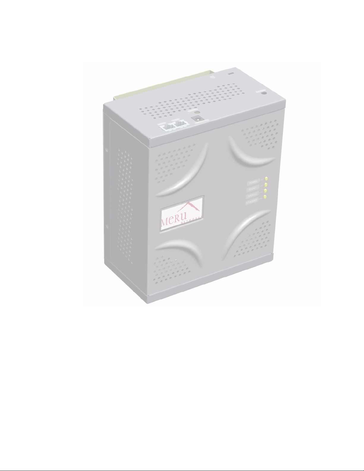
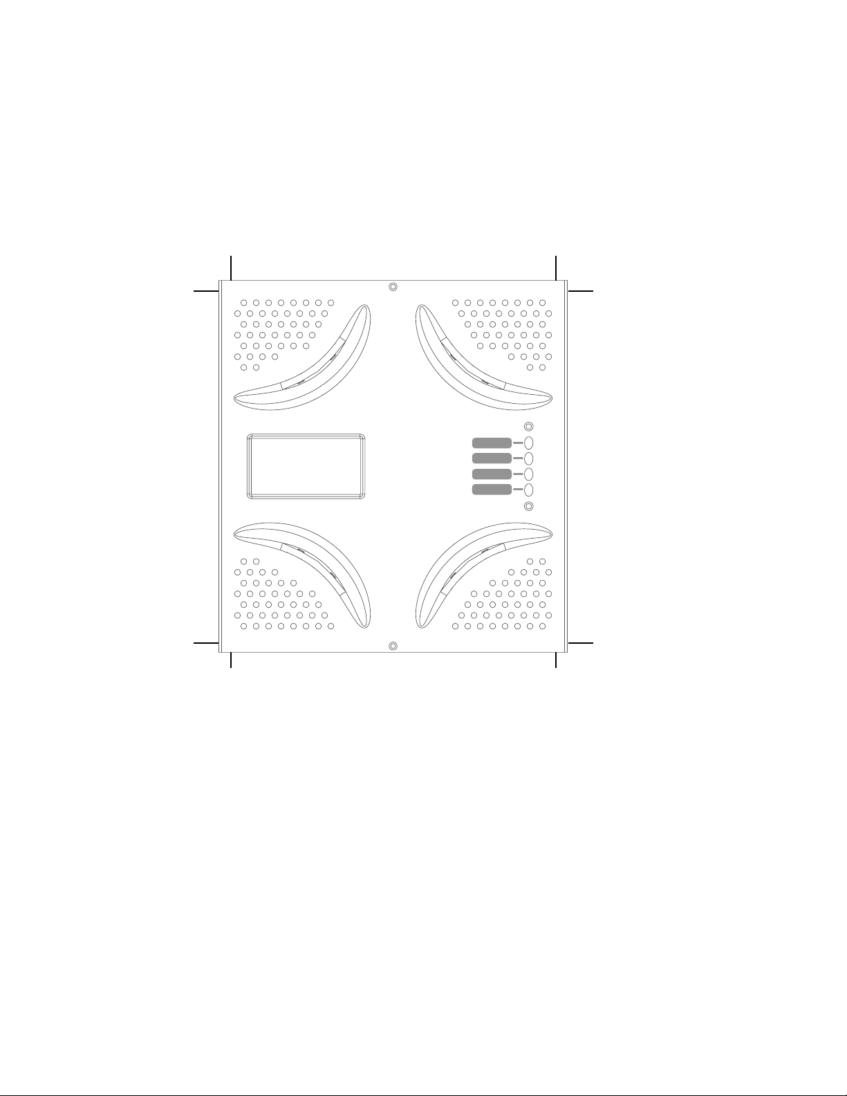
Figure 1: Meru Radio Switch RS4000
Hardware Features and Specifications
Meru’s Radio Switch, RS4000 contains four 802.11 (two 802.11a and two 802.11bg) radios that can
transmit and receive simultaneously on four different channels to increase the total available wireless
bandwidth at a given area. The RS4000 must be connected to the LAN using one or two 10/100 Mbps
Ethernet connections and can also be powered over Ethernet—using two IEEE 802.3af POE
connections, with 15W power on each connector.
2 Meru Radio Switch RS4000 Reference Guide
The RS4000 works in conjunction with an external wideband RF combination omni directional
(WRC/OD) antenna. Only one antenna is needed for simultaneous operation of all radios of an
RS4000 in both the 2.4GHz and 5GHz bands. The antenna must be connected to the Radio Switch
using any one of the low-loss antenna cables provided in the antenna packaging.
The RS4000 is a blade-server-type modular design for field-upgrades. By replacing the radio blade
inside the RS4000, a higher number of 802.11a/bg radios and/or 802.11n can be supported.
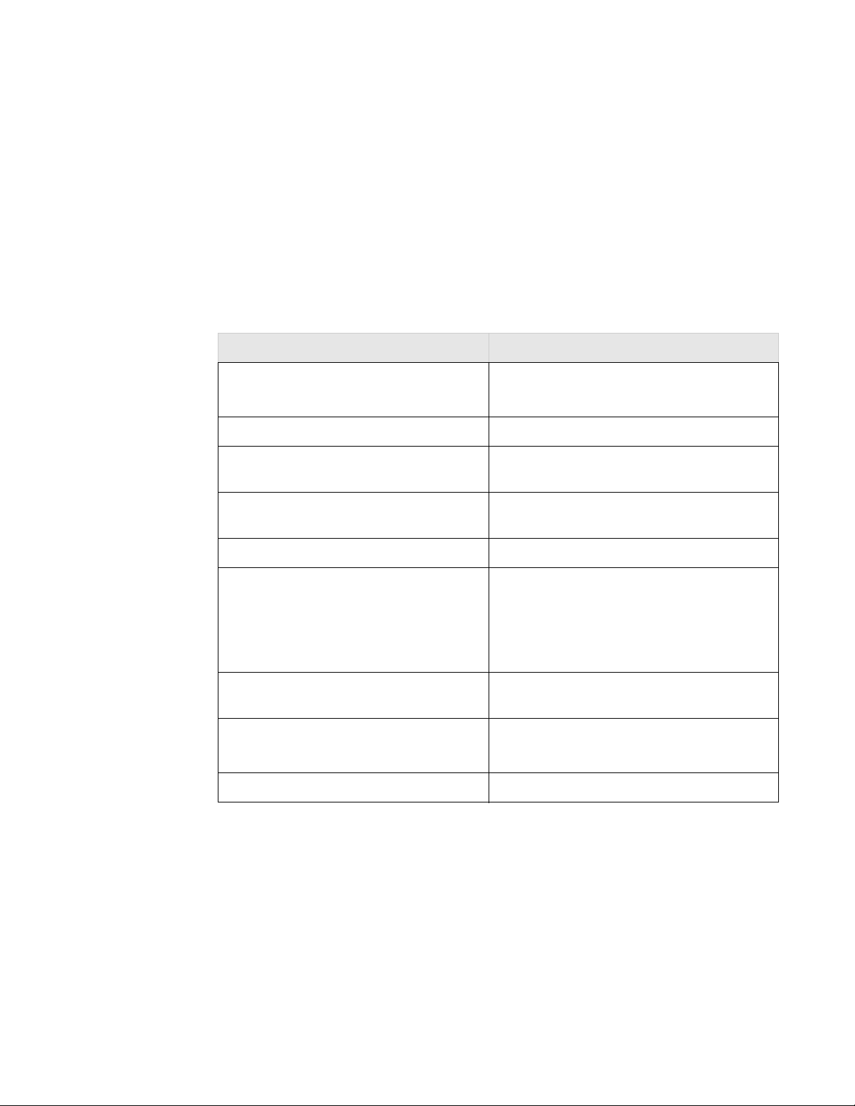
The following table lists the key hardware features of the RS4000.
Table 1: RS4000 Hardware Features
Feature Description
802.11 Connectivity Two 802.11bg radios (2.4GHz)
Two 802.11a radios (5 GHz)
Ethernet Connectivity Two auto-sensing 10/100 Mbps ports
Power Provided by two 802.3af Power Over Ethernet
connections (11W per connector)
LEDs Power, Radio Activity, and Ethernet Activity
LEDs per radio
Dimensions 9.5" x 8.5" x 3.875"
Mounting Options RS4000 has mounting brackets for:
z Ceiling Mount
z Wall Mount
z Inside NEMA Enclosures (Hoffman, etc)
Antenna Wideband RF Combination/Omni-Directional
(WRC/OD) Antenna. 5dBi gain. Indoor use.
Antenna Cables 3’ low-loss cables (default option)
6’ and plenum-rated cables (available option)
Field-Upgradability Modular radio blade for upgrades
About the Radio Switch RS4000 3

WLAN Features and Specifications
z 802.11a and 802.11b/g client connectivity
z Four ESSIDs and four BSSID support
z L2 Security
— WEP-64 and WEP-128
— 802.1X PEAP
— Dynamic load balancing
— VLAN tagging support
Management and Monitoring
Connect to the switch for management and monitoring is provided with the following:
z Allows a maximum of two connections via SSH and Telnet (including two simultaneous SSH
sessions or two Telnet sessions; or one of each ) For SSH sessions, the SecureCRT and SSH
Sessions applications are verified for inter operability.
z Console over Ethernet support for local administration
z SNMP v1 & v2c support for remote management
z IOS-like Command Line Interface (CLI)
z Syslog for remote logging
4 Meru Radio Switch RS4000 Reference Guide

This chapter describes how to physically install the Meru RS4000. It contains the following sections:
z Planning the Installation
z Performing the Installation
Planning the Installation
Before performing the installation, be sure that you understand and have read the following sections:
z Prerequisites and System Requirements
z Check Product Package Contents
z Safety Precautions
Chapter 2
Installing the RS4000
z Installation Guidelines
Prerequisites and System Requirements
The following prerequisites and system requirements must be met:
z Layer 2 connection to RS4000 from PC or Laptop for configuring initial network management
settings
z 2 IEEE 802.3 PoE connections— one to each Ethernet port, yielding a maximum power
specification of 15W per port
z Network switch for connecting all networking components
z Telnet or SSH application
Check Product Package Contents
Confirm that the RS4000 shipping package contains the following items:
z Omni-directional antenna with 2 antenna cables and mounting bracket
z RS4000 with mounting bracket and mounting plate
z CD-ROM containing RS4000 software and documentation
Installing the RS4000 5

Planning the Installation
z
RS4000 Release Notes
Safety Precautions
Follow the guidelines in this section to ensure proper operation and safe use of the Radio Switch.
FCC Safety Compliance Statement
The FCC with its action in ET Docket 96-8 has adopted a safety standard for human exposure to radio
frequency (RF) electromagnetic energy emitted by FCC certified equipment. When used with
approved Meru Radio Switch antennas, Meru RS4000 product meets the uncontrolled environmental
limits found in OET-65 and ANSI C95.1, 1991. Proper installation of this radio according to the
instructions found in this manual will result in user exposure that is substantially below the FCC
recommended limits.
General Safety Guidelines
z Do not touch or move antenna(s) while the unit is transmitting or receiving.
z Do not hold any component containing a radio so that the antenna is very close to or touching any
exposed parts of the body, especially the face or eyes, while transmitting.
z The use of wireless devices in hazardous locations is limited to the constraints posed by the local
codes, the national codes, and the safety directors of such environments.
Warnings
Translated versions of the following safety warnings are provided in Appendix F.
Warning!
should be located at a minimum of 7.9 inches (20 cm) or more from the body of all persons.
Warning!
explosive environment unless the device has been modified to be especially qualified for such use.
Warning!
activity.
Warning!
Warning!
Ensure that a fuse or circuit breaker no larger than 120 VAC, 15A U.S. (240 VAC, 10A international)
is used on the phase conductors (all current-carrying conductors).
In order to comply with FCC radio frequency (RF) exposure limits, dipole antennas
Do not operate your wireless network device near unshielded blasting caps or in an
Do not work on the system or connect or disconnect cables during periods of lightning
Read the installation instructions before you connect the system to its power source.
This product relies on the building's installation for short-circuit (overcurrent) protection.
6 Meru Radio Switch RS4000 Reference Guide

Installation Guidelines
The RS4000 requires a location that meets the following:
z A location to mount the antenna within 3’ of the RS4000 and with relatively unobstructed access
to the client stations
z Power over Ethernet (PoE) connection to the network switch servicing the RS4000.
The RS4000 obtains power from 802.3af standard Power over Ethernet (PoE) compatible network
switch or PoE power injector installed between the switch and the RS4000.
Select a location with minimal physical obstructions between the RS4000 antenna and the wireless
stations. In a classroom, mounting the RS4000 on the wall near the ceiling provides the least
obstructed communications path.
Most installations receive the best coverage using the following guidelines:
z Do not install the antenna near metal objects, such as heating ducts, metal doors, or electric service
panels.
z Relative to the ground, orient the antenna up or down, not sideways.
Planning the Installation
Note:
The previous guidelines are general guidelines. Each site has its own unique environment.
Place antenna accordingly.
The RS4000 is only intended for installation in Environment A as defined in IEEE 802.3af. All
interconnected equipment must be contained within the same building, including the interconnected
equipment's associated LAN connection.
Installing the RS4000 7
Planning the Installation
You need the tools listed in Tabl e 2.
Table 2: RS4000 Installation Tools
Installation Type Tools Required
Vertical mounting over a wall stud
Vertical mounting on sheetrock
z Drill
z 1/8"drill bit
z Screwdriver
z (Optional) Pliers
z Drill
z 3/16" drill bit
z Screwdriver
z (Optional) Pliers
About an Hoffman Enclosure Installation
The recommended RS4000 installation is a wall mount, but if necessary the RS4000 can be housed
inside a protective (NEMA) box made by Hoffman that is manufactured with external corner tabs for
standard wall mounting, above or below a ceiling.
Meru leaves the placement and orientation of the Hoffman enclosure to the customer. It will be
necessary to drill holes through the plastic enclosure with a Meru-provided template to enable the
antenna and Ethernet cabling to exit the enclosure. Instructions for performing this task are provided
in the section “Creating Cable Pass-through Holes in the Hoffman Enclosure” on page 14.
Optimum Antenna Positioning and Placement
Warning!
from all users and bystanders. For the protection of personnel working in the vicinity of inside
(downlink) antennas, the following guidelines for minimum distances between the human body and
the antenna must be observed.
The installation of the indoor antenna must be such that, under normal conditions, all personnel cannot
come within 20 cm. (~ 8.0 in.) from any inside antenna. Exceeding this minimum separation will
ensure that the employee or bystander does not receive RF-exposure beyond the Maximum
Permissible Exposure according to FCC CFR 47, section 1.1310 i.e. limits for General
Population/Uncontrolled Exposure.
8 Meru Radio Switch RS4000 Reference Guide
Inside antennas must be positioned to observe minimum separation of 20 cm. (~ 8 in.)

Performing the Installation
Installation Summary
The summary of the steps to install the RS4000 are as follows:
z Initial Configuration of the RS4000
z Wall Mounting the RS4000
or
z Hoffman Enclosure RS4000 Installation
z Power On Components
z Checking LED Activity
Initial Configuration of the RS4000
Performing the Installation
Before the RS4000 is installed in its permanent location, perform an initial RS4000 configuration to
assign its IP addressing.
For this configuration, place the RS4000 on a Layer 2 subnet (192.168.1.x/24) with a PC or laptop so
a Telnet or SSH connection to the RS4000 can be made using the default IP address 192.168.1.1. This
address is used to initially connect to the RS4000 so you can set networking addresses before the
RS4000 is deployed in its permanent location.
Once the Telnet/SSH conection is made to the RS4000, you will be prompted to log on. Use the default
admin login name with the default password, admin.
Changing the Default System Password and SNMP Community Strings
Caution!
strings that allow documented access to the management interfaces. It is strongly recommended that
you change these default settings as soon as possible to prevent unauthorized access to your system.
The commands to perform these changes follow.
To change the admin password:
# passwd new_password
Changing password for admin
Re-enter new password: new_password
Password changed.
As shipped, the system is set with a default password and default SNMP community
Installing the RS4000 9

Performing the Installation
Once the password is changed, it takes effect immediately (usually the command activate-conf must
be used to activate a change). However, the password is active only for the current session. To save
the password so it remains in affect after a reboot, it must followed with the commands activate-conf
and save-conf.
Note:
The system checks for passwords that are too simple or similar.
To change the SNMP community strings:
# set snmpcommunity ROCommunityString new_string
# set snmpcommunity RWCommunityString new_string
# set trapcommunity TrapCommunityStr new_string
Configuring the RS4000 Networking Parameters
Determine whether to allow DHCP to assign IP addressing for the RS4000 or whether a static IP
address will be used. Confer with your network administrator to ensure conformance with your site’s
network configuration strategy.
Configuring DHCP-assigned Addressing
By default, static IP addressing is set for the RS4000. To allow a DHCP server to assign an IP address,
use the following command:
# set ip boot_protocol dhcp
Configuring Static IP Addressing
To change the default static IP address of 192.168.1.1 to another static IP address and netmask, use
the following commands. You should also configure the default gateway IP address:
# set ip boot_protocol static addr ip_address netmask netmask
# set ip gateway ip_address
Configuring Domain Name
To set the domain name, use the command:
# set ip domain domain_name
Configuring DNS Servers
You can configure up to four DNS servers to be used with the RS4000. In the following command,
replace the DNS server number (1 for this example) with the number that you are currently
configuring:
# set ip dns1 ip_address
10 Meru Radio Switch RS4000 Reference Guide

Performing the Installation
Activating and Saving Changes
After making your configuration changes, it is necessary to activate them using the command
activate-conf. Changes are then propagated and started on all radios and will continue running until
the system is rebooted.
To make sure changes are retained after a system reboot, you must save the active (running)
configuration to a startup configuration file, using the command save-conf.
Checking the Network Configuration
Before exiting network configuration session, check that the settings are correct and to your
satisfaction:
# show ip
[ip]
Boot Protocol : Static
IP Address : 10.0.221.14
Network Mask : 255.0.0.0
Default Gateway : 10.0.0.20
Domain : merunetworks.com
DNS1 : 10.0.0.10
DNS2 : 10.0.0.40
DNS3 : 65.182.161.201
DNS4 : 206.13.28.12
If you configured DHCP, you have to use a third-party application to see the address that has been
assigned to the RS4000.
Exiting the Initial Configuration
Once you have confirmed the correct IP address, exit the RS4000 CLI by typing quit at the prompt.
Disconnect the RS4000 and proceed to the physical installation instructions. Depending on the type
of installation you will be performing, use the procedure:
z Wall Mounting the RS4000
z Hoffman Enclosure RS4000 Installation
Wall Mounting the RS4000
Note:
cable, such as those used to secure laptop computers (for example, Kensington cable locks).
To wall mount an RS4000:
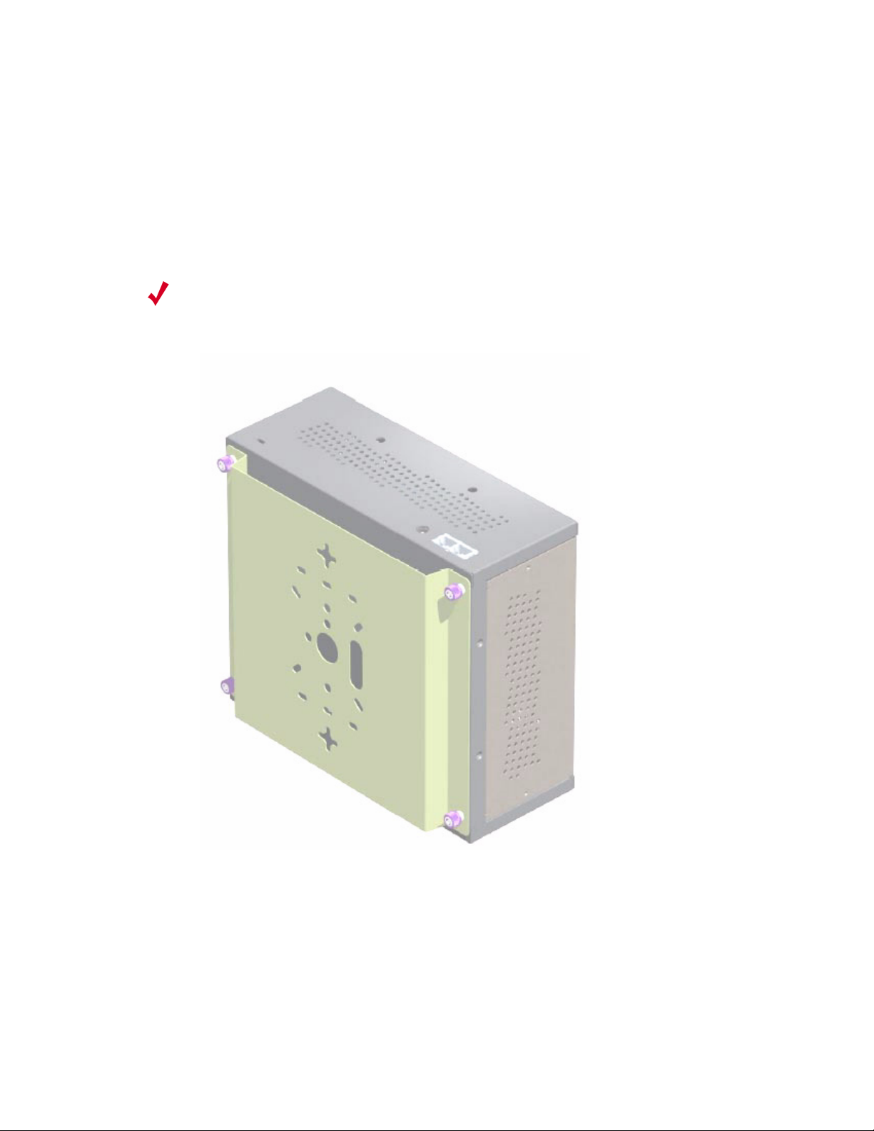
1. Remove the bracket from back side the RS4000 if it is attached by unscrewing each of the 4
The RS4000 has a security cable slot so you can secure the RS4000 with a standard security
knurled thumbscrews (see Figure 2).
Installing the RS4000 11
Performing the Installation
2. Choose the location on the wall where the RS4000 will be mounted. The RS4000 can be oriented
3. Using the bracket holes as a template, mark the location on the wall for the two RS4000 bracket
in any direction, but it is probably more convenient if the SMA antenna mounts are at the top. This
orientation is more convenient for reading LED status.
mounting screws. They are placed 5 25/32" (147mm) apart, center-to-center, one above the other.
If you are not using plastic wall anchors, you must center the mounting screws on a wall stud.
Note:
The RS4000 mounting bracket provides holes to accommodate many types of common
installations such as over a junction box, etc. This procedure describes only the standard wall mount.
Figure 2: Bracket Attached to RS4000
4. Drill holes at the locations you marked:
— 3/16-inch holes if you are using plastic anchors
— 1/8-inch holes if you are using only the screws
5. If you are using plastic anchors, install them in the holes.
6. Screw in the screws most of the way, so that the screw head is about 1/16 of an inch from the wall.
12 Meru Radio Switch RS4000 Reference Guide
Performing the Installation
7. Mount the bracket on the screws, placing the circular portion of the keyhole mounts over the
screw heads and sliding the bracket down.
8. Tighten the screws to secure the bracket.
9. On the RS4000, attach the two antenna cables to the SMA antenna connectors labeled
ANT 2 on the top panel of the RS4000 (see Figure 4) by turning the cable ends clockwise until
ANT 1 and
tight.
10. Attach two Ethernet cables to the Ethernet ports labeled
ETH 1 and ETH 2 on the top panel of the
RS4000.
11. Align the RS4000 to the bracket (against the wall) and tighten the four knurled thumbscrews until
secure. If necessary, apply extra tightening with pliers.
12. Attach the antenna cables to the antenna, as described in “Placing and Positioning the
Antenna.”
13. Connect the two Ethernet cables to the PoE device.
Placing and Positioning the Antenna
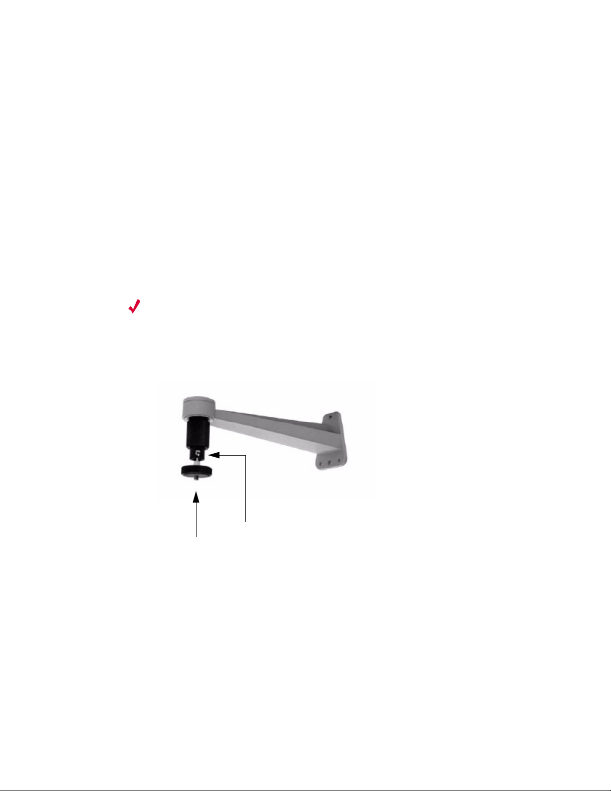
The RS4000 antenna should be mounted to the wall within 6’ of the RS4000 using a standard camera
bracket with 1/4-20 mounting screw. The optional Light-Duty Camera Mount bracket (part number
MN-ACC-RS4000-WCM) is available from Meru Networks. The recommended orientation is shown
in Figure 3.
Set screw on swivel head
1/4-20 Threaded stud
Figure 3: Antenna Mounting Bracket
The RS4000 antenna uses two 6’ RF cables to connect to the SMA connectors on the top panel of the
RS4000 (see Figure 4). The RF cables should be attached to the RS4000 as a result of the procedures
described in “Wall Mounting the RS4000.”
Mount the antenna and connect the cables as described in the following:
1. Using the screwholes in the mounting bracket as a template, mark and drill holes into the wall.
2. Attach the bracket securely with three 1/4" diameter fasteners or one 5/16" diameter and one 1/4"
diameter fastener if mounting to a wall stud (fasteners are not supplied).
3. Connect the RF antenna wires from the RS4000 to the SMA connectors on the top of the antenna.
Installing the RS4000 13

Performing the Installation
4. Attach the top of the antenna to the 1/4-20 threaded stud on the swivel head and tighten the nut
against the antenna.
5. Loosen the set screw on the swivel assembly, if necessary, with the Allen wrench that is provided.
6. Position the antenna to maximize the reception and tighten the set screw.
Hoffman Enclosure RS4000 Installation
Use the procedures in this section to mount the RS4000 within the Hoffman enclosure. It will be
necessary to modify the Hoffman enclosure by drilling cable pass-through holes before installing the
RS4000.
Note:
air flow through the unit. The option to install the RS4000 within a Hoffman enclosure is left to the
customer’s discretion, based on site-specific factors such as protection and accessibility, etc.
Installation in the Hoffman enclosure requires drilling air vents and cable pass-through holes.
The recommended Meru installation is a vertical wall mount, which allows for unimpeded
Creating Cable Pass-through Holes in the Hoffman Enclosure
To create cable pass-through holes in the Hoffman enclosure, Meru supplies a template with markings
that coincide with the placement of the Ethernet and antenna cable locations on the RS4000.
Depending on the orientation of the RS4000 installation in the Hoffman enclosure, the template is to
be used on the side of the enclosure adjacent to the RS4000 top panel, where the cables connect.
1. Open the lid of the empty Hoffman enclosure to provide unimpeded access to the enclosure sides.
2. On the outside of the empty Hoffman enclosure, locate the top center of the side where the cables
will exit.
3. Using the pattern on the supplied template, mark the center of the holes and drill a 1/2" to 1" hole
at each of the three locations specified by the template.
Mounting the RS4000 in the Hoffman Enclosure
To mount the RS4000 in the Hoffman enclosure, it is necessary to use the mounting plate that is
supplied with the RS4000 packing items. This procedure assumes the Hoffman enclosure is already
mounted at the site.
1. Remove the bracket from back side the RS4000 if it is attached by unscrewing each of the 4
knurled thumbscrews.
2. Attach the mounting plate to the back of the RS4000 with four 6-36 screws. The plate is larger
than the RS4000, and the overlap portion has screw holes that match up with the screwholes in
the Hoffman enclosure.
3. Attach the two antenna cables to the SMA antenna connectors labeled
top panel of the RS4000 (see Figure 4) by turning the cable ends clockwise until tight.
14 Meru Radio Switch RS4000 Reference Guide
ANT 1 and ANT 2 on the
Performing the Installation
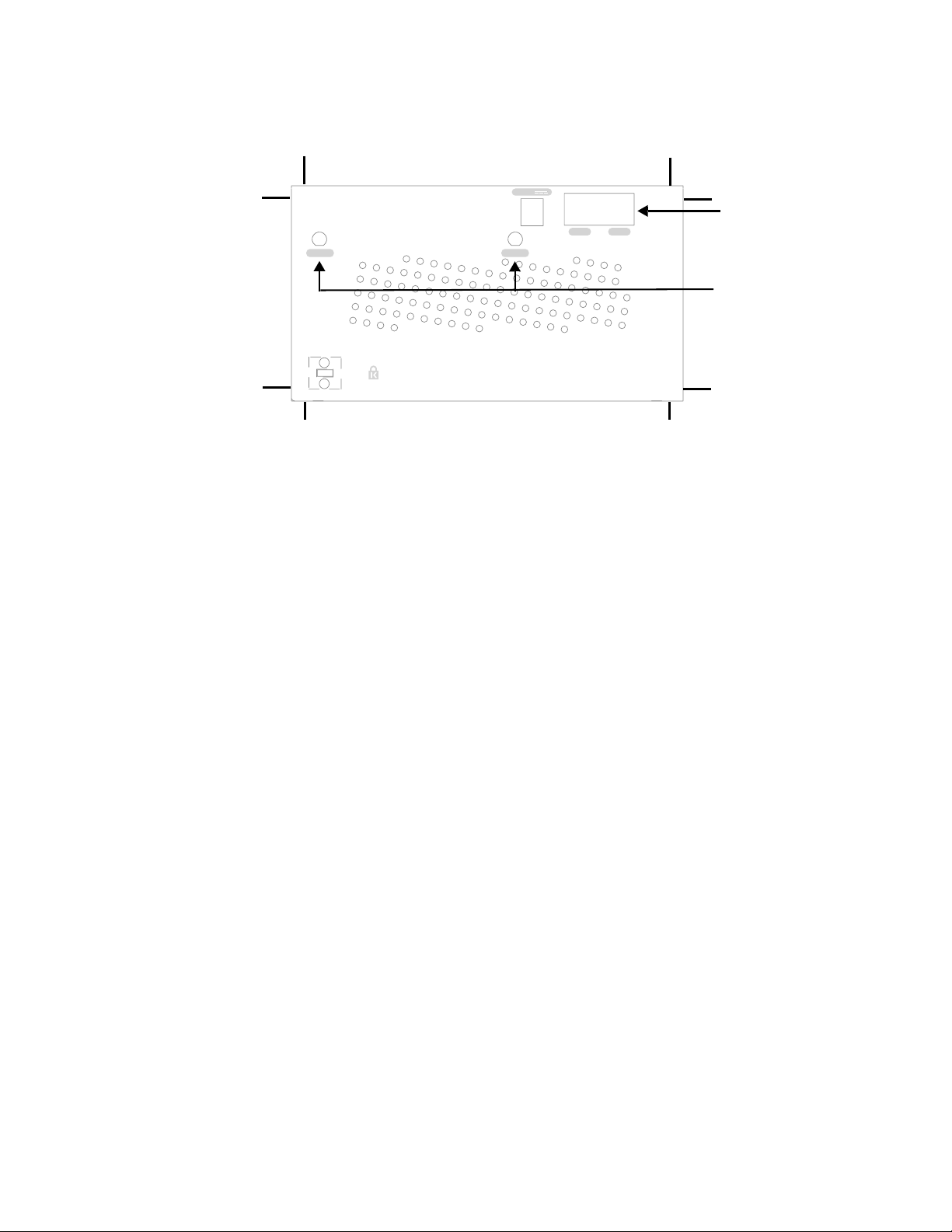
5V DC
ETH 1 and ETH 2
ETH 1ETH 1
ETH 2ETH 2
ANT 2ANT 2ANT 1ANT 1
ANT 1 and ANT 2
Figure 4: RS4000 Top Panel
4. Attach two Ethernet cables to the Ethernet ports labeled
ETH 1 and ETH 2 on the top panel of the
RS4000.
5. Place the RS4000 into the Hoffman enclosure, and align the plate screwholes with the holes in the
Hoffman enclosure.
6. Pass the Ethernet and antenna cables out of the Hoffman enclosure through the cable pass-through
holes, if necessary.
7. Tighten the captive screws on the mounting plate to the Hoffman enclosure.
8. Attach the antenna cables to the antenna.
9. Position and align the bottom of the antenna over the threaded stud on the antenna mount arm and
tighten the threaded stud to the antenna.
10. Test the reception for the antenna and then securely tighten the antenna.
11. Close the lid to the Hoffman enclosure and secure the lock.
12. Connect the two Ethernet cables to the PoE device.
Power On Components
Apply power to the PoE component and network switch to power up the RS4000. Continue with the
software configuration in the next chapter.
Installing the RS4000 15
Performing the Installation
Checking LED Activity
Radio switch status LEDs are provided on the face of the RS4000.
RS4000 Status LEDs
Status LEDs on the face of the RS4000 light, as shown in Figure 5.
.
POWER
POWER
RADIO IRADIO I
RADIO II
RADIO II
ETHERNET
ETHERNET
Figure 5: RS4000 Status LEDs
The RS4000 uses 4 LEDs. The functions of the status LEDs are described in Tabl e 3.
16 Meru Radio Switch RS4000 Reference Guide

Table 3: RS4000 LED Descriptions
LED Function
Performing the Installation
Power
Radio I
Radio II
Ethernet
The Power status LED status is as follows:
z off—power is off
z solid red—when power is applied, system initializes for 40 seconds and then
LED turns green; otherwise, system is in an abnormal state (notify Customer
Support)
z solid amber—at any time, if this LED state persists longer than 40 seconds,
notify Customer Support
z solid green—system is fully operational
The Radio I LED is lit when radio packets are being transmitted and when the
radio is beaconing.
The Radio II LED is lit when radio packets are being transmitted and when the
radio is beaconing.
The Ethernet LED status is as follows:
z off—no link
z solid green—100Mbps connection
z blinking green—transmit or receive activity at 100Mbps
z solid amber—10Mbps connection
z blinking amber—transmit or receive activity at 10Mbps
Installing the RS4000 17

Performing the Installation
18 Meru Radio Switch RS4000 Reference Guide

Chapter 3
Configuring the Meru RS4000
The configuration of the RS4000 includes the following procedures:
z Determine How the RS4000 Is To Be Managed
z Configuring of the Radio Switch with the CLI Commands
z Activating and Saving Changes
Determine How the RS4000 Is To Be Managed
The RS4000 can be managed remotely with third-party SNMP Manager software or directly with the
CLI via a Telnet or SSH connection.
Using the CLI with a Telnet/SSH Connection
Using the IP address configured in Initial Configuration of the RS4000, start a Telnet or SSH session
using the newly configured IP address for your RS4000.
After the session is established, you will be prompted to log on. Use the default admin login name
with the newly assigned password, or the default admin password, admin, if you did not change the
password.
Once you have successfully logged in with the admin user ID, you have a full privilege to all CLI
commands. A complete listing of the CLI commands, their keywords and arguments, can be found in
Appendix A, “Command Reference.”
Note:
A maximum of two Telnet/SSH connections are allowed to the RS4000 at any time.
Using SNMP
The RS4000 contains SNMP agent software that can be utilized by a standard SNMP manager to
communicate with and manage the RS4000. The complete set of Meru Enterprise MIB Tables are
listed in Appendix B, “MIB Definition Reference.” By default SNMP access is enabled.
Configuring the Meru RS4000 19

Determine How the RS4000 Is To Be Managed
Caution!
As shipped, the system is set with a default password and default SNMP community
strings that allow documented access to the management interfaces. It is strongly recommended that
you change these default settings as soon as possible to prevent unauthorized access to your system.
The commands to perform these changes follow.
To start using SNMP, the following needs to be established:
z The IP address and community string of the server running the SNMP manager that can establish
Read Only sessions.
z The IP address and community string of the server running the SNMP manager that can establish
Read Write sessions.
When configuring the SNMP manager access, you can allow specific managers SNMP access by
defining the IP address of that manager, or allow all SNMP managers access, by using the default IP
address 0.0.0.0.
Configuring the SNMP Manager Settings
The commands to allow the SNMP Manager to communicate with the agent that resides in the RS4000
establish the type of SNMP operations the manager can perform. The SNMP manager can be
configured for ReadOnly operations, which allow SNMP get operations, or ReadWrite, which allow
SNMP get/set operations. Using the ReadWrite access allows remote configuration of the RS4000,
when used with the writable MIB objects.
Configuring ReadOnly Managers
The following commands enable ReadOnly communication (1), and set the IP address and community
string (used as a password) for an SNMP manager at IP address 192.168.200.100:
# set snmpcommunity ROPrivilege 1
# set snmpcommunity ROCommunityString CatsCradle
# set snmpcommunity ROManagerIpAddress 192.168.200.100
To allow all SNMP managers in the network to have read access, do not use the command set
snmpcommunity ROManagerIpAddress. Instead, the default setting 0.0.0.0 is used to allow all
SNMP managers with the community string CatsCradle.
Note:
If need be, the default IP address can be reset by using the 0.0.0.0 address as argument to
the IP address command (snmpcommunity ROManagerIpAddress).
Configuring ReadWrite Managers
The following commands enable ReadWrite communication (1), and set the IP address and
community string (used as a password) for an SNMP manager at IP address 192.168.300.100:
# set snmpcommunity RWPrivilege 1
# set snmpcommunity RWCommunityString CatsCradle
20 Meru Radio Switch RS4000 Reference Guide

Configuring of the Radio Switch with the CLI Commands
# set snmpcommunity RWManagerIpAddress 192.168.300.100
To allow all SNMP managers in the network to have read/write access, do not use the command set
snmpcommunity ROManagerIpAddress. Instead, the default IP address setting 0.0.0.0 is used to
allow all SNMP managers with the community string CatsCradle to get/set MIB objects.
Note:
If need be, the default IP address can be reset by using the 0.0.0.0 address as argument to
the IP address command (snmpcommunity RWManagerIpAddress).
Configuring of the Radio Switch with the CLI Commands
This section describes additional commands to configure the RS4000, as shown in following sections:
z Configuring the WLAN Parameters
z Configuring an ESSID
z Configuring System Security
z Configuring Radio Parameters
Configuring the WLAN Parameters
The set wif command performs the configuration of the wireless and security properties for the
interface. An interface must be specified in each of the commands and the radio interface determines
the 802.11 operating mode and some associated features. For example, radio1-1 and radio1-2 operate
in mode 802.11a and radio2-1 and radio2-2 operate in either 802.11bg or b mode.
To see the default settings, use the show factoryconfig command. .
meru_ap# show factoryconfig
[system_config]
host_name=meru_ap
syslog_server=
[network_config]
boot_proto = static
ip_addr = 192.168.1.1
mask = 255.255.255.0
def_gateway=
domain=
dns1=
dns2=
dns3=
dns4=
Configuring the Meru RS4000 21

Configuring of the Radio Switch with the CLI Commands
[radio1-1]
status = up
essid = meru1-1
mode = 11a
channel = 36
rate = auto
tx_power = 30
rts_threshold = 2312
dtim_period = 1
publish_ssid = enable
beacon_interval = 100
vlan_tag = 0
[radio2-1]
status = up
essid = meru2-1
mode = 11g
channel = 1
rate = auto
tx_power = 30
rts_threshold = 2312
short_preamble = enable
dtim_period = 1
publish_ssid = enable
beacon_interval = 100
vlan_tag = 0
[radio1-2]
status = up
essid = meru1-2
mode = 11a
channel = 149
rate = auto
tx_power = 30
rts_threshold = 2312
dtim_period = 1
publish_ssid = enable
beacon_interval = 100
vlan_tag = 0
[radio2-2]
status = up
essid = meru2-2
mode = 11g
channel = 11
rate = auto
tx_power = 30
rts_threshold = 2312
short_preamble = enable
dtim_period = 1
publish_ssid = enable
beacon_interval = 100
vlan_tag = 0
[wifsec_radio1-1]
22 Meru Radio Switch RS4000 Reference Guide

security_mode = none
wep_security_mode = shared
wep_key_len = wep64
tx_key_idx = 1
rekey_period = 300
reauth_period = 3600
[wifsec_radio2-1]
security_mode = none
wep_security_mode = shared
wep_key_len = wep64
tx_key_idx = 1
rekey_period = 300
reauth_period = 3600
[wifsec_radio1-2]
security_mode = none
wep_security_mode = shared
wep_key_len = wep64
tx_key_idx = 1
rekey_period = 300
reauth_period = 3600
Configuring of the Radio Switch with the CLI Commands
[wifsec_radio2-2]
security_mode = none
wep_security_mode = shared
wep_key_len = wep64
tx_key_idx = 1
rekey_period = 300
reauth_period = 3600
[radius]
primary_server_ip = 10.0.0.1
primary_server_port = 1812
secondary_server_ip = 10.0.0.2
secondary_server_port = 1812
[load_balancing]
action = start
interval = 1000
mode = strict
[snmp_agent]
sysContact = RSswitchApAgent
sysName = meru_ap
sysLocation = meru_ap
read_com_str = public
read_mgr_ip = 0.0.0.0
read_com_access = read
write_com_str = test2
write_mgr_ip = 0.0.0.0
write_com_access = write
trap_com_str = test2
trap_mgr_ip = 10.0.0.21
uname = admin
Configuring the Meru RS4000 23

Configuring of the Radio Switch with the CLI Commands
upasswd = admin
Configuring an ESSID
The RS4000 allows each of the interfaces to have a separate ESSID. By default, meru1-1 is specified
for radio1-1 and meru1-2 for radio1-2; meru2-1 is specified for radio2-1 and meru2-2 for radio2-2.
To change the ESSID, for example to chemestry_lab, use the following commands:
# set wif radio2-1 essid chemestry_lab
# set wif radio2-2 essid chemestry_lab
Configuring System Security
The RS4000 security options include WEP-128 and WEP-64 encryption and 802.1X authentication
and encryption with PEAP. Procedures to configure these features are described in the following
sections.
Setting WEP Parameters
To configure radio2-1 for WEP128, with key index 2 and the hex key 135792468011:
# set wif radio2-1 security_mode wep
# set wif radio2-1 key_index 2
# set wif radio2-1 key1 0x1357924680111
Setting 802.1X Interoperability
The following commands set the primary RADIUS server IP address to 10.0.0.30, with a shared secret
of 2for10is, and port 1812.
# set radius primary_ip 10.0.0.30
# set radius primary_secret 2for10is
# set radius primary_port 1812
To configure radio1-1for 802.1X security:
# set wif radio1-1 security_mode 8021x
The default settings of 3600 seconds for a reauthentication period and 300 seconds for a rekey interval
are used.
Configuring Radio Parameters
Operating parameters for radio settings such as the channel, rate, transmit power, and short preamble
can be changed for each radio interface. The available settings are determined by the radio band
present on the interface, for example, 802.11bg interfaces have channels 1-11 and 802.11a have
channels 36, 40, 44, 48, 52, 56, 60, 64, 149, 153, 157, 161, 165.
For this release of product, following channel usage is recommended:
24 Meru Radio Switch RS4000 Reference Guide

Activating and Saving Changes
For 802.11bg radios:
z Channel 1 and Channel 11
For 802.11a radios, use any of the following combinations:
z Channel 36 and Channel 48
z Channel 40 and Channel 52
z Channel 44 and Channel 56
z Channel 48 and Channel 60
z Channel 52 and Channel 64
# set wif radio1-1 channel 36
# set wif radio1-2 channel 48
# set wif radio2-1 channel 1
# set wif radio2-2 channel 11
The following commands set rates for 802.11bg interfaces and 802.11a
interfaces:
# set wif radio1-1 rate 24
# set wif radio1-2 rate 36
# set wif radio2-1 rate 6
# set wif radio2-2 rate 11
The following commands set power for 802.11bg interfaces and 802.11a interfaces:
# set wif radio1-1 tx_power 15
# set wif radio1-2 tx_power 15
# set wif radio2-1 tx_power 15
# set wif radio2-2 tx_power 15
The following commands set long preamble for 802.11bg interfaces:
# set wif radio2-1 short_preamble disable
# set wif radio2-2 short_preamble disable
Activating and Saving Changes
After making your configuration changes, it is necessary to activate them using the command
activate-conf. Changes are then propagated and started on all radios and will continue running until
the system is rebooted.
To make sure changes are retained after a system reboot, you must save the active (running)
configuration to a startup configuration file, using the command save-conf.
Configuring the Meru RS4000 25

Activating and Saving Changes
26 Meru Radio Switch RS4000 Reference Guide

Managing and Monitoring the RS4000
This chapter describes tasks to maintain optimal operating conditions and monitor the performance of
the RS4000.
Managing the RS4000
An important part of maintaining optimal performance for the RS4000 is performing image upgrades
as they become available from Meru. This section describes the steps to obtain an upgrade image from
the Meru FTP site and then apply the image to upgrade the RS4000.
Another helpful procedure is to keep a copy of the working configuration at another site for
safekeeping. The procedure to upload the configuration file to a remote server is also described.
Chapter 4
Saving the Configuration to a Remote Server
Configuration files that are saved off-box should not be edited with a text editor. The only
Note:
Best practice recommendations include saving a copy of the configuration to a remote server to
safeguard against accidental removal or destruction of a valid working configuration. To send a
configuration to a remote server (for example 10.0.220.58), use the following command:
# upldconf tftp_ip 10.0.220.58
Upload of nms.conf complete
changes to the configuration file should result from changes made on the RS4000, using
the CLI commands.
Upgrading the System Software
Upgrading the system software is recommended when new images are released from Meru that
include additional features or fixes. The images are usually located on the Meru Networks FTP site.
The steps to perform an upgrade to the RS4000 software follow:
1. Be sure to save your running configuration (if you want to keep any changes you made to this
point):
Managing and Monitoring the RS4000 27

Monitoring the RS4000
2. As a best practice, ensure that your configuration is backed up to a remote server:
3. Use the download command to download a new new software image file into the RS4000 flash
4. Use the upgrade local command to upgrade the current image to the newly downloaded image:
5. The RS4000 automatically reboots as part of the upgrade procedure. Wait 2-3 minutes and
# save-conf
Configuration Saved Successfully!
# upldconf tftp_ip 10.0.220.58
Upload of nms.conf complete
memory. In the following example, the image RS4000_pkg_11_0_06.tar resides on the server at
10.0.220.58
# download ip 10.0.220.58 image RS4000_pkg_11_0_06.tar
Download Complete
# upgrade local image RS4000_pkg_11_0_06.tar
Upgrade Complete
reconnect via telnet or SSH and log in as admin.
Meru RS4000 (00:01:02)
(c) 2004 Meru Networks, Inc.
All Rights Reserved
Unauthorized access or use of this system is strictly prohibited.
meru_ap login: admin
Password:
RS4000 v1.00-pre10 (2005.06.20-15:40+0000) Built-in shell (ash)
Enter 'help' for a list of built-in commands.
6. Check RS4000 configuration after reboot.
# show running-conf
Monitoring the RS4000
Various show commands allow you to check the system configuration and statistics to monitor the
system performance.
Checking System Details
To check the basic system details, use the commands show system and show wif:
# show system
28 Meru Radio Switch RS4000 Reference Guide

[system]
Description : Access Point
Up Time(hh:mm:ss.ff) : 04:30:23.41
Contact : RSswitchApAgent
Name : meru_ap
Location : meru_ap
Serial Number : 00:10:C6:AA:11:13
AP Type : RS4000
Boot Version : 1.0
Software Version : 1.1-131
Host Name : meru_ap
Syslog Server : 0.0.0.0
# show wif
[radio1-1]
ESSID : cwon-testap
Operational Mode : 11a
Rate : auto
Channel : 36
Short Preamble : disable
Tx Power : 30
ESS Vlan Tag : 0
DTIM Period : 1
Publish ESSID : enable
Beacon Interval : 100
Rekey Period : 300
Re-authentication Period : 3600
Key Length : wep128
Security Mode : WEP
Transmission Key Index : 1
Wep Security Mode : shared
WEP Key1 : **************
WEP Key2 : **************
WEP Key3 : **************
WEP Key4 : **************
Monitoring the RS4000
(and so on, for each radio interface)
Checking Syslog Messages
Syslog messages are generated and sent to the log file on the syslog server that is configured with the
set system syslog_server IP_address command. These message are sent when critical events occur
in the WLAN. A sample syslog message follows:
03072005_RS_SYSLOG_10
Managing and Monitoring the RS4000 29

Monitoring the RS4000
The list of syslog messages are as follows:
03072005_RS_SYSLOG_10 Radio Switch has successfully booted. This message contains
the IP address and MAC address of the Radio Switch and also
Identifies the device type as RS4000.
03072005_RS_SYSLOG_20 FLASH corruption has occurred. The software is then reset to
factory defaults.
03072005_RS_SYSLOG_30 An upgrade process has been initiated on the RS4000.
03072005_RS_SYSLOG_40 An upgrade process has been successfully completed on the
RS4000.
03072005_RS_SYSLOG_50 An upgrade process has failed on the RS4000.
03072005_RS_SYSLOG_60 The admin user has logged into the RS4000.
03072005_RS_SYSLOG_70 The admin user has logged out of the RS4000.
03072005_RS_SYSLOG_80 The admin user is unable to log into the RS4000.
03072005_RS_SYSLOG_90 The RADIUS server has switched from Primary to Secondary
or vice versa. The IP address of the RADIUS Server to which
the switch is made is included.
Checking Security Options
Check the settings for the security options using the show wif and show radius commands. Check the
example output of the show wif command above. Included are the Security Mode settings (WEP or
802.1X), and the various details that are determined by the mode selected. For example, the WEP
Keys, Key Index position, and so forth.
If 802.1X is selected, the RADIUS settings for the primary and secondary server can be checked with
the show radius command:
meru_ap# show radius
[radius]
IP Address Primary RADIUS Server : 10.0.0.1
Port of Primary RADIUS Server : 1812
Shared Secret of Primary RADIUS Server : *********
IP Address Secondary RADIUS Server : 10.0.0.2
Port of Secondary RADIUS Server : 1812
Shared Secret of Secondary RADIUS Server : *********
Checking Network Settings
Use the show ip command to check the network settings:
# show ip
Network Configuration:
30 Meru Radio Switch RS4000 Reference Guide

---------------------Boot Protocol : dhcp
IP Address : 172.16.0.74
Network Mask : 255.255.0.0
Default Gateway : 172.16.0.1
Domain : merunetworks.com
DNS1 :
DNS2 :
DNS3 :
DNS4 :
Checking whether you have connectivity with the network can be checked with the ping command,
once you see the IP address of the RS4000:
172.16.0.74
ping
Checking Wireless Statistics
To check the wireless statistics for the entire Radio Switch, use the show dot11counters command
(see the command reference page, “show dot11counters” on page 69 for descriptions of the various
statistics).
Monitoring the RS4000
You can also check statistics for a particular interface by specifying that interface (radio1-1, for
example), as shown in the following example:
# show dot11counters radio1-1
[radio1-1]
Transmitted Fragment Count : 0
Multicast Transmitted Frame Count : 0
Failed Count : 26688
Retry Count : 296975
Multiple Retry Count : 0
Frame Duplicate Count : 217
RTS Success Count : 0
RTS Failure Count : 0
ACK Failure Count : 0
Received Fragment Count : 0
Multicast Received Frame Count : 0
FCS Error Count : 2861434
Transmitted Frame Count : 433603
WEP Undecryptable Count : 0
Managing and Monitoring the RS4000 31

Monitoring the RS4000
32 Meru Radio Switch RS4000 Reference Guide

Appendix A
Command Reference
This appendix provides complete descriptions of the commands that are available from the
CLI prompt. The following alphabetically lists the available commands:
z ?
z activate-conf
z dldconf
z download
z format
z history
z help
z passwd
z quit
z reboot
z reset-to-default
z save-conf
z set configsnmp
z set interfaces
z set ip
z set loadbalance
z set radius
z show history
z show interfaces
z show ip
z show led
z show loadbalance
z show radius
z show runningconfig
z show snmpcommunity
z show startupconfig
z show system
z show unsavedconfig
z show wif
z upgrade
z updldconf
z set snmpcommunity
z set system
z set wif
z setenv
z show assocStations
z show configsnmp
z show dot11counters
z show factoryconfig
Command Reference 33

?
Displays help for the CLI.
Syntax ?
Usage Use the ? to display online help for all commands or for a single command to show the
available keywords and parameters. The ? can be used at any point on the command line to
receive help at that point.
Examples Use the following command to display all available commands:
# ?
help -> Display this message
show -> Display system state and configuration information
set -> Issue a single configuration command
format -> Set output display format to CLI Table, CLI Pretty or
CLI Plain
history -> Display list of previous commands
setenv -> Set CLI session environment variables
quit -> Exit the CLI
upgrade -> Upgrade system image
upldconf -> Upload system configuration
dldconf -> Download system configuration
save-conf -> Save Running(Active) configuration in flash
activate-conf -> Activate(Apply) unsaved configuration
reset-to-default -> Reset system configuration to factory
default
reboot -> Reboot system
passwd -> Changes password
Use the TAB key for unique command completion, the ? key for help,
the up/down arrow keys to cycle through previous commands, and
Ctrl-U to kill the current line.
Use the following command to display help for the set system command:
#set system ?
system [Contact <value>] [Name <value>] [Location <value>] [hostname
<value>] [syslog_server <value>]
Related
help
Commands
34 Meru Radio Switch RS4000 Reference Guide

activate-conf
Activates the changes made to the current configuration.
Syntax activate-conf
Usage Use this command to activate recently configured parameter changes that have been made to
the system. Once activated with this command, the configuration changes are active but are
temporary and only valid for the current session. Changes must be saved with the command
save-conf if the system is to retain these changes after a system is reboot.
To see the configuration once it has been activated, use the command show running-conf. To
see unsaved configuration changes, use the command show unsaved-conf. To see the saved
configuration, use the command show start-conf.
Examples Use the following command to activate the current configuration:
# activate-conf
Related
Commands
save-conf
reboot
show runningconfig
show startupconfig
Command Reference 35

dldconf
Downloads a configuration file.
Syntax dldconf tftp_ip ip_address
ltftp_ip ip_address Specifies the IP address of the TFTP server where the
configuration file is located.
Usage Use this command to retrieve and download a configuration file that is located on a remote
TFTP server, specified by the ip-address argument.
To successfully complete the download, before this command is invoked, the configuration
file, nms.conf, should be copied to the /tftpboot directory on the TFTP server, which is the
default file access location used by the TFTP protocol.
Once the download is complete, the configuration file is stored on the RS4000 but is not used
until it is activated with the activate-conf command. As with all running configurations, to
ensure the configuration is saved and started with the next reboot, use the save-conf
command.
Configuration files that are saved off-box should not be edited with a text
Note:
editor. The only changes to the configuration file should result from
changes made on the RS4000, using the CLI commands.
Examples Use the following command to download the configuration file from the TFTP server at
192.168.10.220:
# dldconf tftp_ip 192.168.10.220
Related
Commands
activate-conf
save-conf
36 Meru Radio Switch RS4000 Reference Guide

download
Downloads a software image.
Syntax download ip tftp_ip_address image file
ip tftp_ip_address Specifies the IP address of the TFTP server where the
image file is obtained.
image file Package (file) name to be used as the upgrade image.
Usage The download command downloads a system image file from a remote TFTP server,
specified by its IP address. The file is downloaded to the RS4000 flash memory for use for a
future system upgrade, using the upgrade command.
Examples The following example downloads an upgrade image (RS4000_pkg_11_0_06.tar) from the
TFTP server at 10.0.220.58:
download ip 10.0.220.58 image RS4000_pkg_11_0_06.tar
Related
upgrade
Commands
Command Reference 37

format
Formats the output of the show command.
Syntax format {clipretty | cliplain | clitable}
clipretty Formats output with some amount of white space separation.
cliplain Formats output with very little white space separation.
clitable Formats output with white space separation that facilitates
readability.
Usage Use this command to format the output of the show command. Each of the keywords formats
the output differently and are used to accommodate how the output is used.
Typically, the clitable keyword is used for the standard table view of output information. The
keywords cliplain and clipretty may be used if the output will be used as input to another
process.
Examples The following shows how the same output is presented using the three keywords:
meru-ap# format clitable
meru_ap# show wif
[radio1-1]
ESSID : cwon-testap
Operational Mode : 11a
Rate : auto
Channel : 36
Short Preamble : disable
Tx Power : 30
ESS Vlan Tag : 0
DTIM Period : 1
Publish ESSID : disable
Beacon Interval : 100
Rekey Period : 300
Re-authentication Period : 3600
Key Length : wep128
Security Mode : WEP
Transmission Key Index : 1
Wep Security Mode : shared
WEP Key1 : **************
WEP Key2 : **************
WEP Key3 : **************
WEP Key4 : **************
38 Meru Radio Switch RS4000 Reference Guide

meru_ap# format clipretty
meru_ap# show wif
wif {
row[3] {
essid "cwon-testap"
mode 11a rate auto
channel 36 short_preamble disable tx_power 30
ess_vlantag 0 dtim_period 1 publish_essid disable
beacon_interval 100 rekey_period 300 reauth_period
3600 key_len wep128 security_mode WEP
key_index 1 wep_auth_mode shared key1
"**************"
key2 "**************"
key3 "**************"
key4 "**************"
}
meru_ap# format cliplain
meru_ap# show wif
wif 3 essid "cwon-testap"
wif 3 mode 11awif 3 rate auto
wif 3 channel 36wif 3 short_preamble disablewif 3 tx_power 30wif 3
ess_vlantag 0wif 3 dtim_period 1wif 3 publish_essid disablewif 3
beacon_interval 100wif 3 rekey_period 300wif 3 reauth_period
3600wif 3 key_len wep128wif 3 security_mode WEPwif 3 key_index
1wif 3 wep_auth_mode sharedwif 3 key1 "**************"
wif 3 key2 "**************"
wif 3 key3 "**************"
wif 3 key4 "**************"
Command Reference 39

history
Displays a history of commands entered.
Syntax history
Usage Shows the 12 most recent commands. Use the up arrow to scroll through the previous
comments, starting with the most recent. While scrolling, use the down arrow to move back.
The history buffer contains the last 12 commands entered at the command line.
Examples The following shows the history of commands entered at the command line:
meru_ap# history
show snmpcommunity
history
setenv
history
Related
Commands
show history
40 Meru Radio Switch RS4000 Reference Guide

help
Displays help for the CLI.
Syntax help
Usage Use the help command to display a list of commands that are available at the prompt. For
example, show all commands at the top level, show all the set commands, or all show
commands.
Examples Use the following command to display all available commands:
# help
help -> Display this message
show -> Display system state and configuration information
set -> Issue a single configuration command
format -> Set output display format to CLI Table, CLI Pretty or
CLI Plain
history -> Display list of previous commands
setenv -> Set CLI session environment variables
quit -> Exit the CLI
upgrade -> Upgrade system image
upldconf -> Upload system configuration
dldconf -> Download system configuration
save-conf -> Save Running(Active) configuration in flash
activate-conf -> Activate(Apply) unsaved configuration
reset-to-default -> Reset system configuration to factory
default
reboot -> Reboot system
Related
Commands
Use the TAB key for unique command completion, the ? key for help,
the up/down arrow keys to cycle through previous commands, and
Ctrl-U to kill the current line.
?
Command Reference 41

passwd
Changes the system password.
Syntax passwd new-password
Usage Use this command to change the current password. Initially, the system password is set to
admin. This should be changed immediately to prevent unauthorized access to the system.
Once the password is changed, it takes effect immediately (usually the command activate-
conf must be used to activate a change). However, the password is active only for the current
session. To save the password so it remains in affect after a reboot, it must followed with the
commands activate-conf and save-conf.
Note:
The system checks for passwords that are too simple or similar.
Examples Use the following command to change the current password, the default password admin, in
this case:
# passwd new_password
Changing password for admin
Old password: admin
Re-enter new password: new_password
Password changed.
Related
Commands
activate-conf
save-conf
42 Meru Radio Switch RS4000 Reference Guide

quit
Exits the CLI.
Syntax quit
Usage Use the quit command to exit the CLI session.
Examples The following command gracefully exits from the CLI session:
# quit
Command Reference 43

reboot
Reboots the system.
Syntax reboot
Usage Use this command to reboot the system and restart the system with the configuration that was
last saved with the command save-conf.
Examples Use the following command to reboot the system:
# reboot
Related
Commands
save-conf
44 Meru Radio Switch RS4000 Reference Guide

reset-to-default
Reboots the system to the factory default settings.
Syntax reset-to-default
Usage Use this command to reboot the system and restart the system with the factory-set default
settings. It may be helpful to use this command when an ill-advised configuration puts the
system in an unrecoverable situation.
Examples Use the following command to reset the system to default settings:
# reset-to-default
Command Reference 45

save-conf
Saves the current configuration.
Syntax save-conf
Usage Use this command to save the current running configuration to permanent system memory.
After the configuration is saved with this command, the next time the system boots, the system
starts running with the just-saved configuration. The system configuration is stored in the
system file nms.conf.
Examples Use the following command to save the current configuration:
# save-conf
46 Meru Radio Switch RS4000 Reference Guide

set configsnmp
Enables or disables the SNMP trap collection activity.
Syntax set configsnmp SnmpTrapEnable {1 | 2}
SnmpTrapEnable 1 | 2 Specifies whether SNMP traps are being collected:
z 1—Enabled; Traps are being collected.
z 2—Disabled; Traps are not being collected.
Usage Use this command to enable or disable the collection of SNMP traps. Using this command
requires that the SNMP community settings are configured with the set snmpcommunity
command
Examples Use the following command to enable SNMP trap collection:
# set configsnmp SnmpTrapEnable 1
Related
Commands
set snmpcommunity
set trapcommunity
Command Reference 47

set interfaces
Activates and deactivates interfaces.
Syntax set interfaces if AdminStatus {1 | 2}
if Specifies the radio interface (if) to configure (radio1-1
AdminStatus 1 | 2 Specifies the status mode for the interface. By default,
| radio2-1| radio1-2 | radio2-2).
Two interfaces (radio1-1 and radio1-2) operate in
mode 802.11a and two interfaces (radio2-1 and
radio2-2) operate in either 802.11bg, b, or g mode.
the interfaces are up.
1—Up; Interface is active and can be brought up
2—down; Interface is inactive and is unavailable
Usage Use this command to set a radio interface (for example, radio1-1) status up or down. When
the status is set to 1 (up), the interface is allowed to be brought online. When the status is set
to 2 (down), the interface is unavailable.
Examples Use the following command to enable the interface radio1-1:
# set interfaces radio1-1 AdminStatus 1
Related
show interfaces
Commands
48 Meru Radio Switch RS4000 Reference Guide

set ip
Sets network configuration settings.
Syntax set ip boot_protocol {dhcp | static addr IP_address netmask subnet_address}
set ip gateway IP_address
set ip domain domain_name
set ip dns[1-4] IP_address
dhcp Specifies that the Radio Switch boots with DHCP. The
default setting is static addressing.
static addr IP_address netmask
subnet_address
gateway IP_address Specifies the gateway IP address that the Radio Switch
Specifies that the Radio Switch boots with the static IP
address specified by IP_address and the netmask
specified by subnet_address . By default, the IP
address is set to 192.168.1.1 and the netmask is set to
255.255.255.0.
uses.
domain domain_name Specifies the domain name of the domain where the
Radio Switch resides. The domain name can be a
maximum of 32 characters.
dns1 IP_address
dns2 IP_address
dns3 IP_address
dns4 IP_address
Specifies up to four different DNS IP addresses.
Usage The set ip commands set basic networking parameters that the Radio Switch uses to connect
to the network.
First enter the command set ip boot_protocol static addr IP_address netmask
subnet_address or set ip dhcp to establish how the Radio Switch receives its IP address after
booting up. By default, the RS4000 is configured with the IP address/netmask
192.168.1.1/255.255.255.0. With the setting dhcp, the switch automatically receives its IP
address and associated network mask settings, as well as the gateway IP address from the
DHCP server.
If the static keyword is used , the additional keywords and values for addr and netmask must
be given, as well as the set ip gateway command.
The set ip domain command sets the domain name for the network. The set ip dns1through
set ip dns4 commands allow setting up to 4 Domain Name Server IP addresses, where dns1
is the primary server, dns2 is the secondary server, and so forth.
Command Reference 49

Examples To manually set the Radio Switch IP addressing, use the following example commands:
set ip boot_protocol static addr 10.0.1.100 netmask 255.0.0.0
set ip gateway 10.0.0.20
set ip domain merunetworks
set ip dns1 65.182.161.201
set ip dns2 24.221.161.5
Related
Commands
show ip
50 Meru Radio Switch RS4000 Reference Guide

set loadbalance
Sets the load balancing configuration.
Syntax set loadbalance action {stop | start}
set loadbalance interval milliseconds
set loadbalance mode {strict | smooth}
action 1 | 2 Sets the operational status for load balancing. Available
interval milliseconds Sets the interval in milliseconds for load balancing. The
mode {{1|strict}| {2|smooth}} Sets the load balancing mode. Available settings are:
settings are:
z 1 (or stop)—stop load balancing
z 2 (or start)—start load balancing
minimum interval is 10 milliseconds and the default
interval is 1000 milliseconds.
z 1 (or strict)—strict load balancing (default setting)
z 2 (or smooth)—smooth load balancing
Usage The load balancing feature evenly distributes clients that attempt to associate with a Radio
Switch, ensuring a fair balance of clients among radios on the same band, and within the same
ESSID. By default, load balancing is active to assure both radios are being used equally. The
balancing is determined by the number of clients assigned to each radio band and ESSID, not
the amount of packets being transferred by each client. Load balancing is performed between
the two radios on the same band and ESSID (that is, between both A radios and between both
BG radios on the same RS4000).
By default, four ESSIDs are factory set, meru1-1, meru1-2, meru2-1, and meru-2-
Note:
As a client begins to associate, an inventory of the currently associated clients for the
requested band is taken, and based on the type of balancing mode selected (strict or smooth)
the client is assigned to the radio that is next in line to receive a client.
The different load balancing modes, strict and smooth, allocate clients based on a calculation
of the radio that has a lesser number of clients that are associated. The calculation for smooth
uses more of an averaging method than that used for the strict method. By default, the strict
calculation is set.
2. These should be removed and two ESSIDs created: each that combine the two
radios per band. See set wif to create ESSIDs.
Command Reference 51

Examples To disable Load balancing:
# set loadbalance action 1
To create two ESSIDs:
# set wif radio1-1 essid bandA
# set wif radio1-2 essid bandA
# set wif radio2-1 essid bandG
# set wif radio2-2 essid bandG
To start the load balancing:
# set loadbalance action 2
Related
Commands
set wif
52 Meru Radio Switch RS4000 Reference Guide

set radius
Specifies the RADIUS server configuration.
Syntax set radius primary_ip ip_addr
set radius primary_port port_number
set radius primary_secret secret
set radius secondary_ip ip_addr
set radius secondary_port port_number
set radius secondary_secret secret
primary_ip ip_addr
secondary_ip ip_addr
primary_port port_number
secondary_port port_number
primary_secret secret
secondary_secret secret
Sets the primary (primary_ip ip_addr) and
secondary (secondary_ip ip_addr) RADIUS server
IP address. By default, 10.0.0.1 is set as the primary
IP address and 10.0.0.2 is set as the secondary.
Sets the primary (primary_port port_number) and
secondary (secondary_port port_number)
RADIUS server IP port number. By default, 1812 is
set for both primary and secondary port numbers.
Sets the primary (primary_secret secret) and
secondary (secondary_secret secret) RADIUS
server shared secret. A maximum of 32 characters
can be used for secret. By default, meru123 is set
for the primary secret and secondary secret.
Usage The radius commands configure parameters used to communicate with an existing network
RADIUS server. The RADIUS server is a key component of 802.1X WLAN security, as it
provides access management by checking an access list to authenticate a user that attempts to
join the WLAN. Many sites configure a primary and secondary RADIUS server to ensure the
continued availability of the authentication service, should the primary server become
unavailable.
The RADIUS server IP address must be specified, as well as a shared secret and port number.
Other configuration parameters set with command determine the amount of time a key is valid
before it is automatically changed, and the amount of time clients are allowed to connect to
the Radio Switch before they must reauthenticate themselves.
Examples The following commands set the primary RADIUS server IP address to 10.0.0.30, with a
shared secret of 2for10is, and port 1812.
# set radius primary_ip 10.0.0.30
# set radius primary_secret 2for10is
# set radius primary_port 1812
Command Reference 53

Related
Commands
set wif
54 Meru Radio Switch RS4000 Reference Guide

set snmpcommunity
Sets the SNMP community values.
Syntax set snmpcommunity ROPrivilege {1| 2}
set snmpcommunity ROCommunityString string
set snmpcommunity ROManagerIpAddress IP_address
set snmpcommunity RWPrivilege {1| 2}
set snmpcommunity RWCommunityString string
set snmpcommunity RWManagerIpAddress IP_address
ROPrivilege 1| 2 Specifies whether Read Only privilege to the agent by
authorized managers is enabled or disabled:
z 1—Enabled
z 2—Disabled
ROCommunityString string Sets the name of the ReadOnly community string,
which is used for authorization and access, similar to a
password. By default, public is set, but any userdefined 32-character string can be used.
ROManagerIpAddress IP_address Sets the IP address for a ReadOnly SNMP Management
Station. By default, the address is set to 0.0.0.0, which
allows all managers read/get access to the agent. If a
unique IP address is set, only that management station
has access to the agent.
RWPrivilege 1| 2 Specifies whether Read Write privilege is enabled to
the agent:
z 1—Enabled
z 2—Disabled
RWCommunityString string Sets the name of the ReadWrite community string,
which is used for authorization and access, similar to a
password. By default, test2 is set, but any user-defined
32-character string can be used.
RWManagerIpAddress
IP_address
Sets the IP address for a ReadWrite SNMP
Management Station. By default, the address is set to
0.0.0.0, which allows all managers get/set access to the
agent. If a unique IP address is set, only that
management station has access to the agent.
Command Reference 55

Usage Use this command to define the SNMP community settings. The SNMP application-layer
protocol supports message-oriented communication between SNMP management stations
and the SNMP agent located on the RS4000.
Caution!
As shipped, the system is set with default SNMP community strings (public) that
allow documented access to the management interfaces. It is strongly recommended that you
change these default strings as soon as possible to prevent unauthorized access to your system.
As a prerequisite, SNMP must be enabled using the command set configsnmp. Then use this
command and the privilege, community string, and manager IP address keywords to configure
the SNMP community. There are two types of SNMP communities:
z ReadOnly (RO)—allows the manager to read/get the SNMP MIB object values on the
RS4000. This allows an SNMP Management Station to view the status of the RS4000.
z ReadWrite (RW)—allows the manager to read and also set SNMP object values on the
RS4000 (except for the community string). Setting object values allows the RS4000 to be
configured remotely from the SNMP Management Station.
The SNMP community string is similar to a password and is used for authentication, privacy,
and authorization services to the SNMP agent.
Examples The following commands enable SNMP ReadOnly permission for the management station at
IP address 192.168.200.100, and uses CatsCradle as the access code:
# set snmpcommunity ROPrivilege 1
# set snmpcommunity ROCommunityString CatsCradle
# set snmpcommunity ROManagerIpAddress 192.168.200.100
Related
Commands
56 Meru Radio Switch RS4000 Reference Guide
set configsnmp
set trapcommunity

set system
Sets system level configuration settings.
Syntax set system Contact name
set system Name RS4000_name
set system Location description
set system hostname hostname
set system syslog_server IP_address
Contact name Specifies an identifying name to be used as the contact
Name RS4000_name Specifies an identifying name for the RS4000.
Location description Specifies descriptive text for where the RS4000 is
hostname hostname Specifies the hostname for the Meru Radio Switch. A
syslog_server IP_address IP address of the system to be used as the syslog server.
reference.
located.
maximum of 32 characters can be used. By default, the
host name is set to meru_ap.
The syslog server is the location where the system log
file resides. See “Checking Syslog Messages” on
page 29 for a complete list of messages.
Usage The set system command configure basic system parameters for identifying the RS4000 and
providing its Regulatory Domain setup. Identification text provides labels for a Contact,
Location description, Name of unit, and Hostname assigned to the Radio Switch. It also allows
you to designate the IP address for the system that is to be used as the syslog server.
Examples To configure the hostname of the Radio Switch to library_RS, use the command:
# set system hostname library_RS
To designate the IP address (192.168.220.1 for example) of the system that is to be used as the
syslog server, use the command:
# set system syslog_server 192.168.220.1
Note:
A complete list of the syslog messages can be found in “Checking Syslog
Messages” on page 29.
Command Reference 57

Related
Commands
show system
58 Meru Radio Switch RS4000 Reference Guide

set trapcommunity
Configures the SNMP trap manager station.
Syntax set trapcommunity TrapCommunityStr string
set trapcommunity TrapCommunityManagerIpAddress IP_address
TrapCommunityStr string Sets the name of the trap community string, which
is used for authorization and access, similar to a
password. By default, test2 is set, but any userdefined 32-character string can be used.
TrapCommunityManagerIpAddress
IP_address
Sets the IP address for a SNMP trap Management
Station. By default, the address is set to 0.0.0.0,
which allows all managers to receive traps from
the agent. If a unique IP address is set, only that
management station can receive traps from the
agent.
Usage Use this command to set an SNMP management station IP address and the community string
that serves as a password to protect access to the SNMP management station. The SNMP
management station can receive SNMP traps from the RS4000 SNMP agent.
An SNMP trap is an unsolicited SNMP message that is sent to a management station. Traps
are sent to convey the data immediately, instead of waiting for the station to poll at some future
time.
Caution!
allow access to the management interfaces. It is strongly recommended that you change these
default strings as soon as possible to prevent unauthorized access to your system.
As shipped, the system is set with documented SNMP trapcommunity strings that
Examples Use the following command to set the community string that authenticates and authorizes the
SNMP trap manager:
# set trapcommunity TrapCommunityStr alabast0r
Use the following command to set the IP address of the SNMP trap manager:
# set trapcommunity TrapCommunityManagerIpAddress 192.168.100.1
Command Reference 59

Related
Commands
set configsnmp
60 Meru Radio Switch RS4000 Reference Guide

set wif
Configures wireless interface settings.
Syntax set wif if essid essid_name
set wif if mode {11a | 11g}
set wif if rate {1 | 2 | 5.5 | 6 | 9 | 11 | 12 | 18 | 24 | 36 | 48 | 54 | auto}
set wif if channel {1-11 | 36 | 40 | 44 | 48 | 52 | 56 | 60 | 64 | 149 | 153 | 157 | 161 | 165}
set wif if short_preamble {enable | disable}
set wif if tx_power 1-30
set wif if ess_vlantag
set wif if dtim_period 0-255
set wif if publish_essid {enable | disable}
set wif if beacon_interval 0-65535
set wif if security_mode {none | 8021x | wep}
set wif if reauth_period 0-65535
set wif if rekey_period 0-65535
set wif if key_len {wep64 | wep128}
set wif if key_index {1 | 2 | 3 | 4 }
set wif if wep_auth_mode {shared | open}
set wif if key[1-4] key
0-4094
if Specifies the radio interface (if) to configure (radio1-1
| radio2-1| radio1-2 | radio2-2).
Two interfaces (radio1-1 and radio1-2) operate in
mode 802.11a and two interfaces (radio2-1 and radio2-
2) operate in either 802.11bg, or b mode.
The interface designation is a mandatory parameter in
all wireless interface commands and is shown as if in
the related command syntaxes.
essid essid_name Specifies the ESSID (Extended Service Set Identifier)
name associated with the radio interface. By default,
ESSID meru1-1 is specified for radio1-1 and meru1-2
for radio1-2; ESSID meru2-1 is specified for radio2-1
and meru2-2 for radio2-2.
The essid_name must be a maximum of 32 characters
and must not contain special characters or spaces. An
ESSID must not mix modes (see below) or load
balancing cannot be performed.
Command Reference 61

mode {11a | 11g} Specifies the operational mode of wireless interface
(11a | 11g). By default, 11a is specified for 802.11a
interfaces (radio1-1 and radio1-2) and 11g is specified
for 802.11bg interfaces (radio2-1 and radio2-2).
When changing the mode, be sure to also change the
rate to correspond.
rate {1 | 2 | 5.5 | 6 | 9 | 11 | 12 | 18 |
24 | 36 | 48 | 54 | auto}
Specifies the transmit data rate (Mbps) of the interface.
By default, auto is set to allow the rate to be set by the
interface mode. Specifically:
z 802.11a supports 6 | 9 | 12 | 18 | 24 | 36 | 48 | 54 | auto
z 802.11b supports 1 | 2 | 5.5 | 11 | auto
z 802.11bg supports 1 | 2 | 5.5 | 6 | 9 | 11 | 12 | 18 | 24 |
36 | 48 | 54 | auto
channel {1-11 | 36 | 40 | 44 | 48 | 52
| 56 | 60 | 64 | 149 | 153 | 157 | 161 |
165}
Specifies the channel (frequency) on which wireless
interface is operating. By default, channel 36 is set for
radio1-1 and 149 for radio1-2 (11a interfaces), and
channel 1 is set for radio2-1 and 11 for radio2-2
(11b/11bg interfaces).
For this release of product, following channel usage is
recommended:
For 802.11bg radios:
z Channel 1 and Channel 11
For 802.11a radios, use any of the following
combinations:
z Channel 36 and Channel 48
z Channel 40 and Channel 52
z Channel 44 and Channel 56
z Channel 48 and Channel 60
z Channel 52 and Channel 64
short_preamble {enable | disable} Specifies whether to enable or disable short preamble.
By default, short preamble can only be enabled if mode
is set to 11g. If short preamble is disabled, long
preamble is used, which may be necessary to ensure
compatibility between the RS and some older WLAN
cards. Using short preamble improves throughput.
stx_power 1-30 Specifies the transmit power level in dBm for the
interface. By default, the power level is set to 30 dBm.
ess_vlantag 0-4094 Specifies the VLAN identification tag to assign to the
62 Meru Radio Switch RS4000 Reference Guide
interface. Valid tags can be from 0 to 4094. The default
setting is 0.

dtim_period 0-255 Specifies the number of beacon intervals that elapse
before broadcast frames are sent. Value must be
between 0 and 255. Setting the DTIM period to a higher
value decreases the frequency of broadcasts sent by the
RS4000. If power save is enabled on clients that are
connected to the RS4000, clients “wake up” less if
fewer broadcasts are sent, which conserves battery life
for the clients. The default beacon DTIM period is 1.
publish_essid {enable | disable} Specifies whether the RS4000 broadcasts the ESSID
(enabled) or not (disabled)
. By default, an ESSID is
broadcast. When an ESSID is broadcast, it is included
in the beacon that gets advertised. Clients using passive
scanning listen for beacons transmitted by access
points. If broadcasting an ESSID is disabled, clients
listening for beacons cannot receive ESSID
information.
beacon_interval {25-500} Specifies the interval in milliseconds between beacon
broadcasts. Setting the beacon interval to a higher value
decreases the frequency of unicasts and broadcasts sent
by the RS4000. If the power-save feature is enabled on
clients that are connected to the RS4000, clients “wake
up” less if fewer unicasts and broadcasts are sent, which
conserves the battery life for the clients. The default
interval is 100.
security_mode {none | 8021x |
wep}
Specifies the mode that will be used to enforce WLAN
security. The default setting is none.
If 8021x is selected, the 802.1X protocol is used and the
set radius command must also be invoked to set the
RADIUS server configuration parameters.
If wep is selected, the following commands must also
be used to set the WEP parameters:
z set wif if key_len
z set wif if key_index
z set wif if wep_auth_mode
z set wif if key[1-4]
reauth_period 0, 3600-65535 Period in seconds after which 802.1X authenticated
wireless clients will be reauthenticated. By default, the
period is set to 3600 seconds. A value of 0 means
reauthentication is disabled.
Command Reference 63

rekey_period 0, 300-65535 Sets the interval that an 802.1X key is valid. After the
amount of time specified by seconds has elapsed, a new
key is automatically generated. Frequently changing the
key is recommended to prevent security breaches. The
default interval is 300 seconds.
When 0 is specified, rekeying is disabled and the key is
valid for the entire session, regardless of the duration.
key_len wep64 | wep128 Specifies the WEP flavor in use. If wep64 is selected,
the WEP64 protocol is used. If wep128 is selected, the
WEP128 protocol is used. By default, If wep64 is
selected.
key_index {1 | 2 | 3 | 4 } Specifies the WEP key transmit index number. Most
station WEP key configurations allow 4 keys. By
default, 1 is set.
wep_auth_mode {shared | open} Sets the WEP security mode for the interface to shared
or open. By default, shared is set. When configured to
shared, unencrypted packets are dropped at phy (before
the packet reaches the driver); when configured to
open, unencrypted packets reach the driver; but
authentication of the station fails.
key1 key
key2 key
key3 key
key4 key
Specifies up to four WEP keys. Keys can be specified in
ASCII or Hex.
z WEP64— 5 ASCII characters or 10 Hex characters
z WEP128—13 ASCII characters or 26 Hex characters
By default, meru1 is set for all four keys.
If a Hex key is to be specified, the key must be prefaced
with the 0x character string.
Usage These commands perform the configuration of the WiFi properties for the interface. The
interface must be specified in each of the commands and the radio interface determines the
802.11 operating mode and some associated features. For example, radio1-1 and radio1-2
operate in mode 802.11a and radio2-1 and radio2-2 operate in either 802.11bg or b modes.
A summary of the default settings for the wireless interface are as follows:
z ESSID: meru1-1 is specified for radio1-1 and meru1-2 is specified for radio1-2; meru2-
1 is specified for radio2-1 and meru2-2 is specified radio2-2
z mode: radio1-1 and radio1-2—802.11a; radio2-1 and radio2-2—802.11g
z rate: auto
z channel: 36 is set for radio1-1 and 149 radio1-2, and channel 1 is set for radio2-1 and 11
radio2-2
z short preamble: enable
z DTIM period : 1
64 Meru Radio Switch RS4000 Reference Guide

Examples
z
ESS VLAN Tag: 0
z publish ESSID: enable
z beacon interval: 100
z key length: wep64
z security mode: none
z transmission key index: 1
z WEP security mode: shared
z WEP keys: meru1
Related
Commands
set radius
Command Reference 65

setenv
Sets the CLI display environment.
Syntax setenv maxlines lines
setenv scrolling {true | false}
maxlines lines Sets the maximum number of lines of the CLI display
scrolling true | false Specifies whether display scrolling is enabled:
to lines. By default, lines is set to 24 and can be 1 and
255.
true—scrolling is enabled (sometimes useful when
interfacing with scripts).
false—scrolling is disabled (default).
Usage Sets the characteristics of the CLI display environment. maxlines determines the number of
lines that are displayed per window. scrolling determines whether displays with more text
than fits in one window scrolls without pressing a key to display more text.
Examples The following sets the maximum lines to 100:
meru_ap# setenv maxlines 100
66 Meru Radio Switch RS4000 Reference Guide

show assocStations
Displays the associated stations.
Syntax show assocStations
Usage This command lists the number of stations that are associated to the RS4000.
Examples The following command shows the number of associated stations:
meru_ap# show assocStations
[radio1-1]
MAC Address : 00:40:96:A9:B0:8D
Received bytes : 1481074
Transmitted bytes : 1402598
RSSI : 21
Command Reference 67

show configsnmp
Displays the SNMP trap collection status.
Syntax show configsnmp
Usage Displays whether SNMP trap collection is enabled for the radio interface. Enabling or
disabling SNMP trap collection is performed with the command set configsnmp. Configuring
trap community is performed with the set trapcommunity command.
Examples The following command shows the SNMP status is enabled:
meru_ap# show configsnmp
[configsnmp]
Related
Commands
Snmp Trap : enabled(1)
set configsnmp
set trapcommunity
68 Meru Radio Switch RS4000 Reference Guide

show dot11counters
Displays Dot11counter statistics.
Syntax show dot11counters [if]
if Optional. Specifies the radio interface to show (radio1-1 | radio2-1|
radio1-2 | radio2-2).
Usage Displays the Dot11radio counter statistics for all wireless interfaces, or with optional
argument, displays statistics for specified interface.
Table 4: Field Descriptions for show dot11couters
Statistic Description
[Interface Index] Unique identification number of the wireless interface.
Failed Count Total number of failed transmissions.
Retry Count Total number of frames that are retransmitted at least once.
Frame Duplicate
Count
RTS Success Count Total number of RTS frames that are successfully transmitted.
Received Fragment
Count
FCS Error Count Total number of packets received which failed Frame Check
Transmit Frame Count Total number of whole frames transmitted, including unicast,
WEP Undecryptable
Count
Total number of frames received more than once.
Total number of frames received that has the fragment bit set.
Sequence validation due to packet corruption.
broadcast, and multicast frames.
Total number of frames received with undecryptable WEP keys
ACKs were not received.
Examples The following shows the wireless interface configuration for radio1-1:
#show dot11counters radio1-1
[radio1-1]
Command Reference 69

Failed Count : 211
Retry Count : 2679
Frame Duplicate Count : 0
RTS Success Count : 0
Received Fragment Count : 0
FCS Error Count : 55982
Transmitted Frame Count : 3501
WEP Undecryptable Count : 0
70 Meru Radio Switch RS4000 Reference Guide

show factoryconfig
Displays the factory-set configuration.
Syntax show factoryconfig
Usage Shows factory-set configuration settings. This command shows the initial settings of all
configuration parameters, and may be helpful to refer to if some user-initiated configuration
changes are not working and you would like to selectively revert to the default settings.
Examples The following shows an except of the factory-set configuration file output:
meru_ap# show factoryconfig
[system_config]
host_name=meru_ap
syslog_server=
Related
Commands
[network_config]
boot_proto = static
ip_addr = 192.168.1.1
mask = 255.255.255.0
def_gateway=
domain=
dns1=
dns2=
dns3=
dns4=
[radio1-1]
show runningconfig
Command Reference 71

show history
Displays a history of commands entered.
Syntax show history
Usage Shows the 12 most recent commands.
Examples The following shows the history of commands entered at the command line:
meru_ap# show history
show snmpcommunity
history
setenv
history
Related
Commands
history
72 Meru Radio Switch RS4000 Reference Guide

show interfaces
Displays the current network interface settings.
Syntax show interfaces if
if Optional. Specifies the interface to show (eth1| eth2 | radio1-1 |
radio2-1| radio1-2 | radio2-2) or 1, 2, 3, 4, 5, 6, respectively).
Usage Use this command to see the Ethernet (eth1 and eth2) and RF interfaces (radio1-1, radio2-
1, radio1-2, and radio2-2) for the RS4000. Alternately, an interface can be specified by a
number (for example, 3 for radio1-1)
Table 5: Field Descriptions for show interfaces
Parameter Description
[Interface Name] The name of the interface, for example, eth1, radio1-1.
Index The index for identifying this interface.
Description Shows a description of the interface.
Type Type descriptor.
Mtu The Maximum Transmission Unit (MTU) for the interface.
Speed (Mbits/sec) The configured speed for the interface.
PhysAddress The MAC address of the interface.
AdminStatus Indicates whether the wireless interface has been enabled
(Up) or taken out of service (Down).
OperStatus Indicates whether the interface is operational (up) or
unavailable (down)
Last Change The date the interface was changed last.
InOctets The number of octets received by this interface.
InUCastPkts The number of unicast packets received by this interface.
InNUCastPkts The number of non-unicast packets received by this interface.
Command Reference 73

Table 5: Field Descriptions for show interfaces
Parameter Description
InDiscards The number of incoming packets discarded by this interface.
InErrors The number of incoming packets with errors on this interface.
InUnknown Protos The number of packets with an unknown protocol received
by this interface.
OutOctets The number of octets sent by this interface.
OutUcastPkts The number of unicast packets sent by this interface.
OutNUcast Pkts The number of non-unicast packets sent by this interface.
OutDiscards The number of outgoing packets discarded by this interface.
OutErrors The number of outgoing packets with errors on this interface.
OutQLen The number of packets in the outgoing packet queue.
Examples Use the following command to display the network interface settings:
# show interfaces
[eth1]
Index : 1
Descr : eth1
Type : 802.3 Ethernet
Mtu : 1500
Speed : 100 Mbps
PhysAddress : 00:10:C6:AA:11:13
AdminStatus : up(1)
OperStatus : up(1)
LastChange : 00:00:00.00
InOctets : 44426679
InUcastPkts : 44426679
InNUcastPkts : 0
InDiscards : 0
InErrors : 2
InUnknownProtos : 0
OutOctets : 0
OutUcastPkts : 0
OutNUcastPkts : 0
OutDiscards : 0
OutErrors : 0
OutQLen : 0
Specific : 0.0
[eth2]
Index : 2
Descr : eth2
74 Meru Radio Switch RS4000 Reference Guide

Type : 802.3 Ethernet
Mtu : 1500
Speed : 100 Mbps
PhysAddress : 00:10:C6:E0:5F:AB
AdminStatus : up(1)
OperStatus : up(1)
LastChange : 00:00:00.00
InOctets : 124770237
InUcastPkts : 124770237
InNUcastPkts : 0
InDiscards : 0
InErrors : 2
InUnknownProtos : 0
OutOctets : 0
OutUcastPkts : 0
OutNUcastPkts : 0
OutDiscards : 0
OutErrors : 0
OutQLen : 0
Specific : 0.0
[radio1-1]
Index : 3
Descr : radio1-1
Type : 802.11 Wireless
Mtu : 2290
Speed : up to 54 Mbps
PhysAddress : 00:10:C6:AA:11:11
AdminStatus : up(1)
OperStatus : up(1)
LastChange : 00:00:00.00
InOctets : 35377531
InUcastPkts : 35377531
InNUcastPkts : 0
InDiscards : 0
InErrors : 1762
InUnknownProtos : 0
OutOctets : 35148684
OutUcastPkts : 0
OutNUcastPkts : 0
OutDiscards : 0
OutErrors : 14
OutQLen : 0
Specific : 0.0
[radio1-2]
Index : 4
Descr : radio1-2
Type : 802.11 Wireless
Mtu : 2290
Speed : up to 54 Mbps
PhysAddress : 00:10:C6:1D:12:88
AdminStatus : up(1)
OperStatus : up(1)
LastChange : 00:00:00.00
Command Reference 75

InOctets : 1820
InUcastPkts : 1820
InNUcastPkts : 0
InDiscards : 0
InErrors : 21057
InUnknownProtos : 0
OutOctets : 32772009
OutUcastPkts : 0
OutNUcastPkts : 0
OutDiscards : 0
OutErrors : 707
OutQLen : 0
Specific : 0.0
[radio2-1]
Index : 5
Descr : radio2-1
Type : 802.11 Wireless
Mtu : 2290
Speed : up to 54 Mbps
PhysAddress : 00:10:C6:AA:11:12
AdminStatus : up(1)
OperStatus : up(1)
LastChange : 00:00:00.00
InOctets : 0
InUcastPkts : 0
InNUcastPkts : 0
InDiscards : 0
InErrors : 229402
InUnknownProtos : 0
OutOctets : 3234900
OutUcastPkts : 0
OutNUcastPkts : 0
OutDiscards : 0
OutErrors : 1340
OutQLen : 0
Specific : 0.0
[radio2-2]
Index : 6
Descr : radio2-2
Type : 802.11 Wireless
Mtu : 2290
Speed : up to 54 Mbps
PhysAddress : 00:10:C6:1D:12:89
AdminStatus : up(1)
OperStatus : up(1)
LastChange : 00:00:00.00
InOctets : 0
InUcastPkts : 0
InNUcastPkts : 0
InDiscards : 0
InErrors : 936447
InUnknownProtos : 0
OutOctets : 32724557
76 Meru Radio Switch RS4000 Reference Guide

OutUcastPkts : 0
OutNUcastPkts : 0
OutDiscards : 0
OutErrors : 8004
OutQLen : 0
Specific : 0.0
Related
Commands
set interfaces
Command Reference 77

show ip
Displays the current network configuration settings.
Syntax show ip
Usage Use this command to see the stored RS4000 IP settings. The IP settings are set with the
command set ip.
Table 6: Field Descriptions for show ip
Parameter Description
Boot Protocol The boot protocol that determines whether the Radio Switch
boots with a static IP address or one assigned using DHCP.
IP Address The IP address for the RS4000. By default, the IP address is
set to 192.168.1.1.
Network Mask The subnet mask for the RS4000 IP address. By default, the
netmask is set to 255.255.0.0
Default Gateway The gateway IP address that the RS4000 uses.
Domain The domain name of the domain where the Radio Switch
resides.
DNS1-DNS4 The addresses for up to four different DNS IP addresses.
Examples Use the following command to display the network addresses settings:
# show ip
[ip]
Boot Protocol : DHCP
IP Address : 10.0.221.14
Network Mask : 255.0.0.0
Default Gateway : 10.0.0.20
Domain : merunetworks.com
DNS1 : 10.0.0.10
DNS2 : 10.0.0.40
DNS3 : 65.182.161.201
DNS4 : 206.13.28.12
78 Meru Radio Switch RS4000 Reference Guide

Related
Commands
set ip
Command Reference 79

show led
Displays the current status of the LEDs.
Syntax show led
Usage Use this command to see the current connection status of the RS4000 IP via LEDs. The LED
status can be:
z Green—The RS4000 is working properly and is enabled.
z Amber—There is a network connectivity problem.
Examples The following example shows the RS4000 LED status:
meru-ap# show led
LED state is Green
80 Meru Radio Switch RS4000 Reference Guide

show loadbalance
Displays the configuration for the Load Balancer.
Syntax show loadbalance
Usage Use this command to display the stored settings for the load balancer feature. Load balancer
settings that display with this command are set with the set loadbalance command.
Examples Use the following command to display stored settings for the load balancer feature.
meru_ap# show loadbalance
[loadbalance]
Action : start
Interval : 1000
Operational Mode : strict
Related
Commands
set loadbalance
Command Reference 81

show radius
Displays running configuration for RADIUS server.
Syntax show radius
Usage Use this command to display the stored RADIUS server settings. Settings that display with
this command are set with the command set radius.
Examples Use the following command to display the RADIUS server settings:
# show radius
[radius]
Related
Commands
IP Address Primary RADIUS Server : 10.0.0.1
Port of Primary RADIUS Server : 1812
Shared Secret of Primary RADIUS Server : *********
IP Address Secondary RADIUS Server : 10.0.0.2
Port of Secondary RADIUS Server : 1812
Shared Secret of Secondary RADIUS Server : *********
set radius
set wif
82 Meru Radio Switch RS4000 Reference Guide

show runningconfig
Show configuration of running system.
Syntax show runningconfig
Usage The configuration shown by this command is stored in "running nms.conf" file and NOT the
actual running configuration of each components. For this configuration to take effect, the
user must use the command save-conf.
Examples The following shows an except of the running configuration:
meru_ap# show runningconfig
[system_config]
host_name=meru_ap
syslog_server=
[network_config]
boot_proto = dhcp
[radio1-1]
status = up
essid = cwon-testap
mode = 11a
channel = 36
rate = auto
tx_power = 30
rts_threshold = 2312
dtim_period = 1
publish_ssid = enable
beacon_interval = 100
vlan_tag = 0
[radio2-1]
status = up
essid = cwon-testap2-1
mode = 11b
channel = 3
rate = auto
tx_power = 30
----More----
Related
Commands
save-conf
Command Reference 83

show snmpcommunity
Displays the SNMP community configuration.
Syntax show snmpommunity
Usage Displays the SNMP community information for the radio interface. The display shows the
community string and IP address settings for configured SNMP managers with the ReadOnly
and ReadWrite privilege.
Configuring an SNMP community string and IP address of the SNMP manager is performed
with the set snmpcommunity command.
Enabling or disabling SNMP is performed with the command set configsnmp.
Configuring trap community and IP address of the SNMP manager that the traps are sent to is
performed with the set trapcommunity command.
Examples The following command shows the SNMP trap collection information; that is, that test2 is the
string used as the password and the traps are being sent to the manager at 10.0.0.21:
meru_ap# show snmpcommunity
[snmpcommunity]
Read Privilege : snmpRo(1)
Read Community String : public
Read Manager IP Address : 0.0.0.0
Read Write Privilege : snmpRw(2)
Read Write Community String : test2
Read Write Manager IP Address : 0.0.0.0
Related
Commands
set configsnmp
set snmpcommunity
set trapcommunity
84 Meru Radio Switch RS4000 Reference Guide

show startupconfig
Show starting configuration of system.
Syntax show startupconfig
Usage The configuration shown by this command is stored in nms.conf file on "flash" and is the
configuration that is used at system boot. However, if the user has executed CLI commands
after system start-up and activated them with the command activate-conf, the executed
command configuration can be viewed by the command show runningconfig.
If the system is rebooted without saving the running configuration, this configuration (the
startupconfig) will again take effect.
Examples The following shows an except of the startup configuration file:
Related
Commands
meru_ap# show startupconfig
[system_config]
host_name=meru_ap
syslog_server=
[network_config]
boot_proto = dhcp
[radio1-1]
status = up
essid = cwon-testap
mode = 11a
channel = 36
rate = auto
tx_power = 30
rts_threshold = 2312
dtim_period = 1
publish_ssid = enable
beacon_interval = 100
vlan_tag = 0
activate-conf
reboot
save-conf
Command Reference 85

show system
Displays the stored system settings.
Syntax show system
Usage Use this command to see the stored RS4000 system settings.
Information such as Description, Contact, Name, Location, Host Name, and Syslog Server are
entered with the command set system. Other entries such as Serial Number, and AP Type are
hardware-specific and cannot be changed. The Up Time, Boot Version, and Software Version
are software-specific and cannot be changed.
Examples Use the following command to display the system settings:
#show system
Related
Commands
[system]
Description : Access Point
Up Time(hh:mm:ss.ff) : 00:00:10.74
Contact : meru_ap
Name : meru_ap
Location : meru_ap
Serial Number : 00:10:C6:AA:11:13
AP Type : RS4000
Boot Version : 1.0
Software Version : 1.1-131
Host Name : meru_ap
Syslog Server : 0.0.0.0
set system
86 Meru Radio Switch RS4000 Reference Guide
 Loading...