


Internal Use Only—Beta Draft
Meru Access Point and
Radio Switch
Installation Guide
Copyright © Meru Networks, Inc., 2003–2008. All rights reserved.
Other names and brands may be claimed as the property of others.
Document Number: 3.6_ap_install_revA2

Internal Use Only—Beta Draft

Internal Use Only—Beta Draft
Contents
About This Guide . . . . . . . . . . . . . . . . . . . . . . .xi
Audience . . . . . . . . . . . . . . . . . . . . . . . . . xi
In This Guide. . . . . . . . . . . . . . . . . . . . . . . . xi
Other Sources of Information . . . . . . . . . . . . . . . . . . xii
Meru Publications . . . . . . . . . . . . . . . . . . . . . xii
External References . . . . . . . . . . . . . . . . . . . . xii
Typographic Conventions . . . . . . . . . . . . . . . . . . . xii
Contacting Meru . . . . . . . . . . . . . . . . . . . . . . xiii
Customer Services and Support . . . . . . . . . . . . . . . . xiii
Chapter 1
Chapter 2
Chapter 3
Meru Access Points and Radio Switch . . . . . . . . . . . . . 1
Meru Access Point AP300 Series . . . . . . . . . . . . . . . . . 1
Meru Access Point AP200 Series . . . . . . . . . . . . . . . . . 3
Meru Access Point AP150 Series . . . . . . . . . . . . . . . . . 4
Meru Access Point OAP180 . . . . . . . . . . . . . . . . . . . 5
Radio Switch RS4000 . . . . . . . . . . . . . . . . . . . . . 6
RS4000 Hardware Features and Specifications . . . . . . . . . . . 7
Installing the AP300 . . . . . . . . . . . . . . . . . . . . 11
Safety Precautions . . . . . . . . . . . . . . . . . . . . . . 11
Unpack the AP300 . . . . . . . . . . . . . . . . . . . . . . 12
Determine Power Requirements . . . . . . . . . . . . . . . . . 13
Installation Requirements . . . . . . . . . . . . . . . . . . . 13
Additional Equipment . . . . . . . . . . . . . . . . . . . 14
Install the AP300 . . . . . . . . . . . . . . . . . . . . . . 15
Select a Location . . . . . . . . . . . . . . . . . . . . . 15
Attach the Antennas . . . . . . . . . . . . . . . . . . . . 15
Install the Access Point . . . . . . . . . . . . . . . . . . . 19
Check AP300 LED Activity . . . . . . . . . . . . . . . . . . . 24
Installing the AP200 . . . . . . . . . . . . . . . . . . . . 27
Safety Precautions . . . . . . . . . . . . . . . . . . . . . . 27
Unpacking the AP200 . . . . . . . . . . . . . . . . . . . . . 27
Installation Requirements . . . . . . . . . . . . . . . . . . . 28
Installing the Access Points . . . . . . . . . . . . . . . . . . . 30
Selecting a Location . . . . . . . . . . . . . . . . . . . . 30
Attaching the AP200 Antennas . . . . . . . . . . . . . . . . 31
Mounting the Access Point . . . . . . . . . . . . . . . . . . 31
© 2008 Meru Networks, Inc. Contents iii

Where to Go From Here . . . . . . . . . . . . . . . . . . . 40
Checking LED Activity . . . . . . . . . . . . . . . . . . . . 41
Ethernet Connector LEDs . . . . . . . . . . . . . . . . . . 41
AP200 Status LEDs . . . . . . . . . . . . . . . . . . . . 42
Chapter 4
Chapter 5
Installing the OAP180 . . . . . . . . . . . . . . . . . . . . 45
Safety Precautions . . . . . . . . . . . . . . . . . . . . . 45
Unpacking the OAP180 . . . . . . . . . . . . . . . . . . . . 46
Installation Requirements. . . . . . . . . . . . . . . . . . . 46
Installing the Access Points . . . . . . . . . . . . . . . . . . 47
Selecting a Location . . . . . . . . . . . . . . . . . . . 47
Test Basic Link Operation . . . . . . . . . . . . . . . . . 49
Mounting the Access Point . . . . . . . . . . . . . . . . . 49
Connect Antennas and Ground Wire to OAP180 . . . . . . . . . . 51
Align Antenna. . . . . . . . . . . . . . . . . . . . . . 54
Where to Go From Here . . . . . . . . . . . . . . . . . . . 55
Checking LED Activity . . . . . . . . . . . . . . . . . . . . 55
Antenna Gain Recommendations . . . . . . . . . . . . . . . 56
Installing the AP150 . . . . . . . . . . . . . . . . . . . . . 59
Safety Precautions . . . . . . . . . . . . . . . . . . . . . 59
Unpacking the AP150 . . . . . . . . . . . . . . . . . . . . 59
Installation Requirements. . . . . . . . . . . . . . . . . . . 60
Installing the Access Points . . . . . . . . . . . . . . . . . . 62
Selecting a Location . . . . . . . . . . . . . . . . . . . 62
Attaching the AP150 Antennas . . . . . . . . . . . . . . . . 63
Mounting the Access Point . . . . . . . . . . . . . . . . . 63
Where to Go From Here . . . . . . . . . . . . . . . . . . . 69
Checking LED Activity . . . . . . . . . . . . . . . . . . . . 70
AP150 Status LEDs . . . . . . . . . . . . . . . . . . . . 70
Chapter 6
iv Meru Access Point and Radio Switch Installation Guide © 2008 Meru Networks, Inc.
Installing the RS4000 . . . . . . . . . . . . . . . . . . . . 73
Safety Precautions . . . . . . . . . . . . . . . . . . . . . 73
Unpacking the RS4000 . . . . . . . . . . . . . . . . . . . . 73
Installation Requirements. . . . . . . . . . . . . . . . . . . 74
About an Hoffman/NEMA Enclosure Installation . . . . . . . . . . 76
Optimum Antenna Positioning and Placement . . . . . . . . . . 77
Installing the RS4000 . . . . . . . . . . . . . . . . . . . . 78
Mounting the RS4000 . . . . . . . . . . . . . . . . . . . 78
Placing and Positioning the Antenna . . . . . . . . . . . . . . 87
Hoffman/NEMA Enclosure RS4000 Installation. . . . . . . . . . . 89
Where to Go From Here . . . . . . . . . . . . . . . . . . . 91
Checking LED Activity . . . . . . . . . . . . . . . . . . . . 92
RS4000 Status LEDs . . . . . . . . . . . . . . . . . . . . 92

Internal Use Only—Beta Draft
Appendix A
Appendix B
Appendix C
Appendix D
Specifications . . . . . . . . . . . . . . . . . . . . . . . 95
Wireless Interface . . . . . . . . . . . . . . . . . . . . . . 95
Ethernet Interface . . . . . . . . . . . . . . . . . . . . . . 97
Physical . . . . . . . . . . . . . . . . . . . . . . . . . 97
AP Accessories . . . . . . . . . . . . . . . . . . . . . . . 99
AP300 Accessories . . . . . . . . . . . . . . . . . . . . . . 99
AP300 PoE Devices . . . . . . . . . . . . . . . . . . . . 99
AP300 Power Supply . . . . . . . . . . . . . . . . . . . . 99
AP300 Antennas . . . . . . . . . . . . . . . . . . . . 100
AP300 Mounting Options. . . . . . . . . . . . . . . . . . 100
AP200 Accessories . . . . . . . . . . . . . . . . . . . . . 101
OAP1800 Accessories . . . . . . . . . . . . . . . . . . . . 101
AP150 Accessories . . . . . . . . . . . . . . . . . . . . . 101
Mounting Bracket Stencils . . . . . . . . . . . . . . . . . . 103
AP150 and AP300 Rev A Mounting Bracket Stencil . . . . . . . . . . 103
AP300 Rev B Mounting Bracket Stencil . . . . . . . . . . . . . . 105
Cautions and Warnings . . . . . . . . . . . . . . . . . . . 107
Cautions . . . . . . . . . . . . . . . . . . . . . . . . 107
Warnings . . . . . . . . . . . . . . . . . . . . . . . . 110
Appendix E
Regulatory Information . . . . . . . . . . . . . . . . . . . 115
For OAP180 . . . . . . . . . . . . . . . . . . . . . . . 115
Radio . . . . . . . . . . . . . . . . . . . . . . . . 115
EMC. . . . . . . . . . . . . . . . . . . . . . . . . 115
Safety . . . . . . . . . . . . . . . . . . . . . . . . 115
USA . . . . . . . . . . . . . . . . . . . . . . . . . . 116
Underwriters Laboratories . . . . . . . . . . . . . . . . . 116
FCC Radiation Exposure Statement . . . . . . . . . . . . . . 117
Radio Frequency Interference Requirements . . . . . . . . . . 117
Canada. Industry Canada (IC) . . . . . . . . . . . . . . . . . 119
Europe—EU Declaration of Conformity and Restrictions . . . . . . . . 121
IEEE 802.11a Restrictions . . . . . . . . . . . . . . . . . 124
EEE 802.11b/g Restrictions. . . . . . . . . . . . . . . . . 124
Japan . . . . . . . . . . . . . . . . . . . . . . . . . 124
Singapore. . . . . . . . . . . . . . . . . . . . . . . 125
Manufacturing Information . . . . . . . . . . . . . . . . . . 125
AP300 Plenum Requirements . . . . . . . . . . . . . . . . . 126
© 2008 Meru Networks, Inc. Contents v

vi Meru Access Point and Radio Switch Installation Guide © 2008 Meru Networks, Inc.

Internal Use Only—Beta Draft
List of Figures
Figure 1 Meru AP 300 ........................................................................ 2
Figure 2 Access Point AP200 ............................................................... 3
Figure 3 Access Point AP150 ............................................................... 5
Figure 4 Rugged OAP180 Access Point .................................................... 6
Figure 5 Radio Switch RS4000 .............................................................. 7
Figure 6 AP320, AP311 or AP302 Antennas 1-6 .......................................... 16
Figure 7 AP310 Antennas 1-3 ............................................................... 17
Figure 8 AP300 Antenna Connection ...................................................... 17
Figure 9 Remote Antenna Mount .......................................................... 18
Figure 10 Mounting the AP300 to a Suspended Ceiling Rail ........................... 21
Figure 11 AP300 Mounted Above a Suspended Ceiling ................................. 22
Figure 12 Attaching the Mounting Bracket to the Box Hanger ........................ 23
Figure 13 AP300 Status LEDs ............................................................... 24
Figure 14 AP200 Mounting Bracket ........................................................ 28
Figure 15 AP200 Antenna Connection ..................................................... 32
Figure 16 AP200 Connector Panel ......................................................... 33
Figure 17 AP200 Bracket .................................................................... 33
Figure 18 Aligning the AP200 with the Bracket ......................................... 34
Figure 19 Sliding the AP200 into the Bracket ............................................ 35
Figure 20 Mounting the AP200 to a Suspended Ceiling Rail ........................... 36
Figure 21 Mounting the AP200 Above a Suspended Ceiling ............................ 38
Figure 22 Box Hanger Mounting Bracket Holes .......................................... 38
Figure 23 Attaching the Mounting Bracket to the Box Hanger ........................ 39
Figure 24 RJ-45 LEDs ........................................................................ 41
Figure 25 AP200 Status LEDs ............................................................... 42
Figure 26 OAP180 Outdoor Access Point ................................................. 46
Figure 27 Sample Physical Layout ......................................................... 47
Figure 28 Square Mounting Bracket Attaches to Bottom of OAP180 ................. 49
Figure 29 Brackets Attached to a Pole ................................................... 50
Figure 30 Connect the Antenna Cables ................................................... 52
Figure 31 OAP180 LEDs ...................................................................... 56
Figure 32 AP150 with Mounting Bracket .................................................. 60
Figure 33 AP150 Antenna Connection ..................................................... 64
Figure 34 AP150 Connector Panel ......................................................... 64
Figure 35 AP150 Bracket .................................................................... 66
Figure 36 Aligning the AP150 with the Bracket ......................................... 67
Figure 37 Mounting the AP150 to a Suspended Ceiling Rail ........................... 68
Figure 38 AP150 Status LEDs ............................................................... 70
Figure 39 RS4000 Package Contents ...................................................... 74
Figure 40 Open NEMA Box Showing Mounting Holes .................................... 77
Figure 41 Bracket Attached to RS4000 ................................................... 79
Figure 42 RS4000 Bracket Mounting ....................................................... 80
Figure 43 RS4000 with Antenna Attached ................................................ 81
Figure 44 Mounting the RS4000 Below a Suspended Ceiling Rail ..................... 82
© 2008 Meru Networks, Inc. List of Figures vii

Internal Use Only—Beta Draft
Figure 45 RS4000 with Antenna Attached ................................................ 83
Figure 46 Mounting the RS4000 Above a Suspended Ceiling ........................... 84
Figure 47 Box Hanger Mounting Bracket Holes .......................................... 85
Figure 48 Attaching the Mounting Bracket to the Box Hanger ........................ 85
Figure 49 RS4000 with Antenna Attached ................................................ 86
Figure 50 RS4000 180
Figure 51 Antenna Mounting Arm with Wall Bracket (shown attached) ............. 88
Figure 52 Antenna Ceiling Tile Rail Base ................................................. 88
Figure 53 RS4000 and Antenna Installed in NEMA Enclosure .......................... 90
Figure 54 RS4000 Status LEDs .............................................................. 92
o
Directional Antenna ............................................. 87
viii Meru Access Point and Radio Switch Installation Guide © 2008 Meru Networks, Inc.

Internal Use Only—Beta Draft
List of Tables
Table 1 RS4000 Hardware Features .............................................. 8
Table 2 Meru AP300 Radios and Antennas ...................................... 12
Table 3 AP300 Power Options ..................................................... 13
Table 4 AP300 Installation Items ................................................. 14
Table 5 Antenna Use for AP320, AP311, and AP302 (Dual Radio Units) ..... 16
Table 6 Antenna Use for AP310 (Single Radio Unit)............................ 17
Table 7 AP300 LED Descriptions .................................................. 25
Table 8 AP200 Installation Items ................................................. 29
Table 9 AP200 Installation Tools ................................................. 30
Table 10 AP200 LED Descriptions ................................................. 43
Table 11 AP200 Controller Status Information ................................. 43
Table 12 Antenna Gain............................................................. 57
Table 13 AP150 Installation Items ................................................ 61
Table 14 AP150 Installation Tools ................................................ 62
Table 15 AP150 LED Descriptions ................................................. 71
Table 16 RS4000 Installation Tools ............................................... 76
Table 17 RS4000 LED Descriptions................................................ 93
Table 18 Wireless Interface Specifications ..................................... 95
© 2008 Meru Networks, Inc. List of Tables ix

Internal Use Only—Beta Draft
x Meru Access Point and Radio Switch Installation Guide © 2008 Meru Networks, Inc.

This guide describes the features and provides installation instructions for the Meru
Access Points, which includes the AP200, OAP180, and AP150 models, and the Radio
Switch RS4000. The term access point is used interchangeably throughout this document to apply to any model when there are no differences among the models.
Audience
Internal Use Only—Beta Draft
About This Guide
This guide is intended for persons installing the Meru Wireless LAN System Access
Point (AP) and Radio Switches.
In This Guide
This guide includes the following chapters:
z Chapter 1, “Meru Access Points and Radio Switch”
z Chapter 6, “Installing the RS4000”
z Chapter 2, “Installing the AP300”
z Chapter 3, “Installing the AP200”
z Chapter 4, “Installing the OAP180”
z Chapter 5, “Installing the AP150”
z Appendix A, “Specifications”
z Appendix D, “Cautions and Warnings”
z Appendix E, “Regulatory Information”
z Appendix D, “Channels”
z Appendix C, “Mounting Bracket Stencils”
z Appendix B, “AP Accessories”
© 2008 Meru Networks, Inc. About This Guide xi

Internal Use Only—Beta Draft
Other Sources of Information
Additional information is available in the following Meru publications, Web site, and
external references.
Meru Publications
z Meru System Director Release Notes
z Meru System Director Getting Started Guide
z Meru Controller Installation Guide
z Meru System Director Command Reference
z Meru System Director Configuration Guide
External References
z Stevens, W. R. 1994. TCP/IP Illustrated, Volume 1, The Protocols. Addison-Wesley,
Reading, Mass.
z Gast, M.S. 2002. 802.11 Wireless Networks, The Definitive Guide. O’Reilly and
Associates, Sebastopol, Calif.
Typographic Conventions
This document uses the following typographic conventions to help you locate and
identify information:
Note:
Caution!
Provides extra information, tips, and hints regarding the topic.
Identifies important information about actions that could result in
damage to or loss of data, or could cause the application to behave in
unexpected ways.
Warning!
© 2008 Meru Networks, Inc. About This Guide xii
Identifies critical information about actions that could result in
equipment failure or bodily harm.

Internal Use Only—Beta Draft
Contacting Meru
You can visit Meru Networks, Inc. on the Internet at this URL:
http://www.merunetworks.com
Customer Services and Support
For assistance, contact Meru Customer Services and Support 24 hours a day at
+1-888-637-8952 (+1-888-Meru-WLA(N)) or +1-408-215-5305. Email can be sent to
support@merunetworks.com.
Meru Networks, Inc. Customer Services and Support provide end users and channel
partners with the following:
z Telephone technical support
z Software update support
z Spare parts and repair service
RMA Procedures
Contact Meru Customer Services and Support for a Return Material Authorization
(RMA) for any Meru equipment.
Please have the following available when making a call:
z Company and contact information
z Equipment model and serial numbers
z Meru software release and revision numbers (for example, 3.0.0-35)
z A description of the symptoms the problem is manifesting
z Network configuration
© 2008 Meru Networks, Inc. About This Guide xiii

Internal Use Only—Beta Draft
© 2008 Meru Networks, Inc. About This Guide xiv
Internal Use Only—Beta Draft
Chapter 1
Meru Access Points and Radio Switch
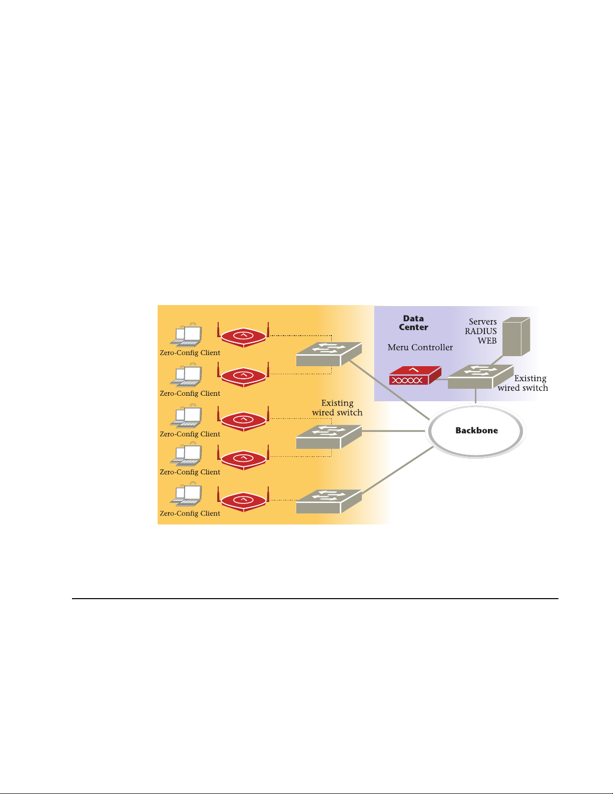
Meru Access Points and Radio Switches contain radio devices that communicate with
the Meru Controller and form the wireless LAN (WLAN). The Meru Controller, Radio
Switches, and Access Points connect to the site’s wired LAN through wired switches.
Wireless clients associate with the Radio Switches and Access Points as they roam
throughout the WLAN. As such, the Meru Wireless LAN System is an extension of the
wired LAN, providing the wireless benefits of client mobility, enhanced access, and
dynamic network configuration.
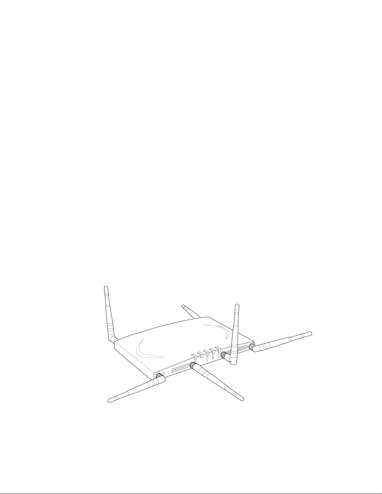
Meru AP
Meru Access Point AP300 Series
The AP300 Access Point delivers high performance, full-speed, Wi-Fi certified
802.11n based on draft 2.0 connectivity while simultaneously supporting legacy
802.11a/b/g devices. Meru AP300 is available in these configurations:
— AP320: Two dual-band 802.11n radios with 3x3 MIMO
— AP310: Single dual-band 802.11n radio with 3x3 MIMO
© 2008 Meru Networks, Inc. Meru Access Points and Radio Switch 1
Internal Use Only—Beta Draft
— AP311: Single dual-band 802.11n radio and single 802.11a/b/g radio (AP320
upgradeable)
— AP302: Two dual-band 802.11a/b/g radios (AP320 upgradeable)
Features for the AP300 include:
z 802.11n support with channel bonding in both 2.4GHz and 5GHz frequency bands.
Channel bonding combines two 20Mhz channels into a single-wide 40Mhz channel
for increased throughput.
z Dual-band external antenna options optimized for MIMO mode
z Plug and Play deployment using centralized controller platforms
z Multi-layered security including standard WPA2, 802.11i security such as
automatic traffic inspection
z Each of these Access points may be powered by a standard 802.3af PoE device.
z Air Traffic Control technology for 802.11n devices and legacy a/b/g devices
z 3x3 MIMO with 3 chains and 3 receive chains, delivering full 300Mbps data rates using 2
spatial streams
z For AP302 and AP311, the a/b/g radio software upgrades to 802.11n for maximum
investment protection.
z Channel span architecture which requires no channel planning or configuration
z Six standard multiband, omni-directional antennas for AP302, AP320 and AP311.
Three standard multiband, omni-directional antennas for AP310.
z Powered by 5 volt DC input, 802.3af compliant PoE device, or draft 802.3at
compliant PoE device.
A
2
R
F
R
2
F
L
1
A
N
A
2
A
2
Figure 1: Meru AP 300
© 2008 Meru Networks, Inc. Meru Access Points and Radio Switch 2
Internal Use Only—Beta Draft
Meru Access Point AP200 Series
The Meru Access Point AP200 series provides two models that conform to the specifications provided by the IEEE 802.11a and 802.11g protocols and provide backward
compatibility for the 802.11b protocol. An AP200 works with most standard Wi-Fi
clients.
z The AP201 houses a single 802.11a/b/g radio device
z The AP208 supports a maximum of two radio devices that can simultaneously run
two protocols (802.11b, g or b/g on interface 1 and 802.11a on interface 2).
Alternately the second radio can be configured to run as an RF monitor to the Meru
Controller, providing real-time status of RF activity to optimize the wireless
network.
The Meru Access Point AP200 series (referred hereafter as the AP200, unless specifically referring to the AP201 or AP208) is housed in a metal case with a plastic removable cover. As such, it can be used for plenum installations when the plastic cover is
removed.
AP200
00109
Figure 2: Access Point AP200
© 2008 Meru Networks, Inc. Meru Access Points and Radio Switch 3

Internal Use Only—Beta Draft
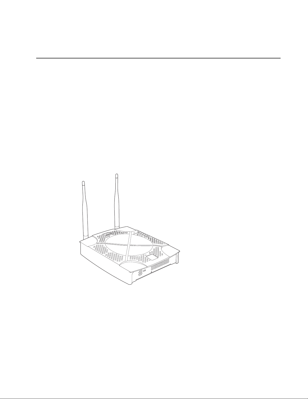
Meru Access Point AP150 Series
Meru Access Point AP150 models may have different revisions, but function-
Note:
The AP150 has two 802.11 radios for simultaneous 802.11a and 802.11b/g WLAN
access. It is an ideal option for enterprise-wide data-only WLAN implementations and
small-sized converged data and voice WLAN implementations. The AP150 works in
conjunction with Meru Controller products and can be easily integrated into existing
Layer 2 and Layer 3 wired network environments to provide enterprise-grade Wi-Fi
access with multi-layered security options, basic VoWLAN support, centralized
configuration, troubleshooting tools, remote management and RF visualization capabilities.
ally they are the same, and all are referred to as the AP150 series. Hereafter
in this document, all AP150 series models are referred to as the AP150.
The Meru Access Point AP150 supplies the following features:
z Dual 802.11b/g and 802.11a radios
z Simultaneously support for 802.11b, 802.11g, and 802.11a clients
z Contention Management for high density of data clients
z Basic VoWLAN QoS support for small density of voice clients
z Multiple ESSIDs with individual security policies to ensure separation of different
user groups or dynamic VLAN assignment per user based on RADIUS credentials
z Zero configuration required at the access point; the installation procedure is a
simple plug-n-play
z Automatic AP discovery, configuration
z Intelligent load balancing of clients
z Layer 2 or 3 connectivity for flexible deployment options
z Locking mechanism secures access point when mounted in public areas
© 2008 Meru Networks, Inc. Meru Access Points and Radio Switch 4
Internal Use Only—Beta Draft
PWR
RADIO1
RADIO2
LAN
Figure 3: Access Point AP150
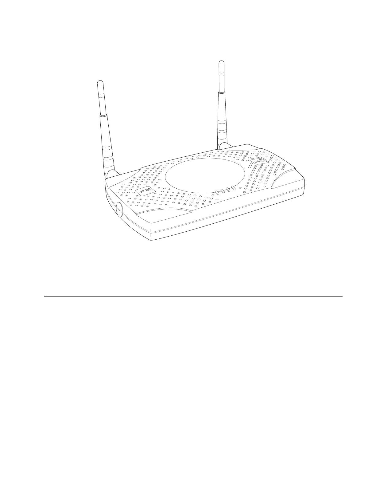
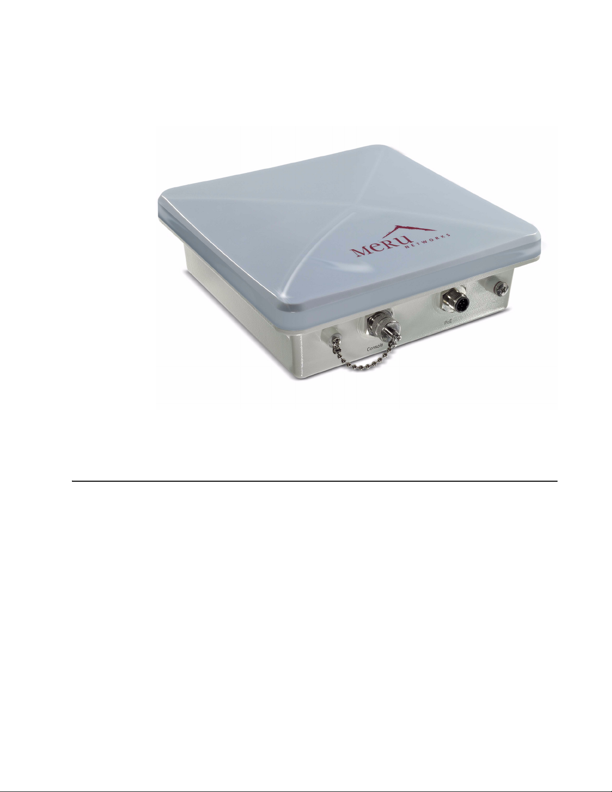
Meru Access Point OAP180
The OAP180 Rugged Access Point with dual 802.11a/bg radios is designed to provide
secure Wi-Fi connectivity to outdoor locations such as campuses, parking lots, and
pole tops, or to harsh indoor locations such as breweries, food processing plants or
warehouses. The OAP180 supports the following features:
z Simultaneous support for 802.11a, 802.11b, and 802.11g clients using dual
802.11a and 802.11b/g radios
z Full support of System Director features
z Automatic AP discovery and configuration
z No channel planning required with single channel installations
00175
z Intelligent load balancing of clients
z PoE (Power over Ethernet) support
z RoHS compliant
© 2008 Meru Networks, Inc. Meru Access Points and Radio Switch 5
Internal Use Only—Beta Draft
z Locking mechanism for security when mounted in public areas
Figure 4: Rugged OAP180 Access Point
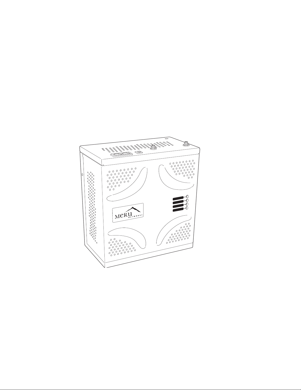
Radio Switch RS4000
The Radio Switch RS4000 enables high-capacity enterprise-class wireless LAN connectivity with full support of standard 802.11 security and network management
features. Each RS4000 contains four 802.11 radios (two 802.11b/g, two 802.11a) for
high data and voice throughput – an essential requirement for high user-density environments with several simultaneous users. Classrooms and convention halls are
typical deployment applications of the Radio Switch. Deploying the Radio Switch is
easy— as with wireless access points, the Radio Switch can be installed wherever
wireless coverage is needed. For large buildings with multiple rooms and floors, more
than one Radio Switch can be installed to cover the desired area. Wireless users can
seamlessly roam from one Radio Switch to another, getting high-capacity WLAN
access throughout the wireless enterprise enabled with multiple Radio Switches. The
RS4000 also balances radio traffic across its RF channels and resolves contention
within each RF channel such that users receive a switched wireless experience with
dedicated bandwidth to execute a variety of applications ranging from web browsing
and VoIP mobility to multimedia streaming.
© 2008 Meru Networks, Inc. Meru Access Points and Radio Switch 6
Internal Use Only—Beta Draft
The RS4000 ships with either a high-gain omni-directional indoor antenna or a 180degree directional indoor antenna that aggregates and layers radio transmissions
from each of the built-in radios. The antenna can broadcast every channel available
to blanket the area around the Radio Switch, yet avoid interference and contention.
This simplifies deployment efforts by eliminating the need for additional antennas
for each radio. More importantly, RF channel planning efforts are greatly simplified.
Using the RS4000, wireless users experience the benefits of switching technology on
Wi-Fi—dedicated bandwidth, traffic separation, and multi-service network support.
The RS4000 can be deployed with up to two 802.11b/g and two 802.11a channels
active on the radio interfaces. The 802.11b/g channels must be separated by a
minimum of 8 channels (for example, channels 1 and 9), so the recommended set is
channels 1 and 11, typically. The 802.11a channels must be separated by a minimum
of 80MHz/16 channels for best performance (for example, channels 36 and 52).
POWER
RADIO I
RADIO II
ETHERNET
Figure 5: Radio Switch RS4000
RS4000 Hardware Features and Specifications
The RS4000 has four 802.11 radios (two 802.11a and two 802.11bg) that transmit and
receive simultaneously on four different channels to increase the total available
wireless bandwidth at a given area. The RS4000 connects to the LAN using one 10/100
Mbps Ethernet connection for each radio pair. The RS4000 is powered using two IEEE
802.3af POE connections, each with 15W power.
00178
© 2008 Meru Networks, Inc. Meru Access Points and Radio Switch 7
Internal Use Only—Beta Draft
.
PoE must be provided on the first Ethernet connector (ETH1); the antenna
Note:
The RS4000 works in conjunction with a wideband RF combination omni directional
(WRC/OD) indoor antenna or a 180-degree directional indoor antenna. Only one
antenna is needed for simultaneous operation of all radios of an RS4000 in both the
2.4GHz and 5GHz bands. The antenna must be connected to the Radio Switch using
any one of the low-loss antenna cables provided in the antenna packaging.
The following table lists the key hardware features of the RS4000.
Table 1: RS4000 Hardware Features
Feature Description
cannot operate correctly without that power source. Power to the second
Ethernet connector (ETH2 ) is optional; if not connected, two of the
radios will not operate.
802.11 Connectivity
Ethernet Connectivity
Two 802.11b/g radios (2.4GHz)
Two 802.11a radios (5 GHz)
Two auto-sensing 10/100 Mbps ports, one
for each radio pair
Provided by two 802.3af POE connec-
Power
tions, one for each radio pair (15W per
connector)
LEDs
Power, Radio Activity, and Ethernet
Activity LEDs per radio
Dimensions 9.5" x 8.5" x 3.875"
RS4000 has mounting brackets available
for:
z Ceiling Mount
Mounting Options
z Wall Mount
z Inside NEMA Enclosures (Hoffman,
etc.)
© 2008 Meru Networks, Inc. Meru Access Points and Radio Switch 8

Internal Use Only—Beta Draft
Table 1: RS4000 Hardware Features
Feature Description
The RS4000 ships with either of these
antennas:
Antenna
Antenna Cables
z Wideband RF Combination/Omni-
Directional (WRC/OD) Antenna. 5dBi
gain. Indoor use.
z 180-degree directional indoor antenna
3’ low-loss cables (default option)
6’ and plenum-rated cables (available
option)
Radio Switch RS4000
© 2008 Meru Networks, Inc. Meru Access Points and Radio Switch 9

Radio Switch RS4000
Internal Use Only—Beta Draft
10 Meru Access Point and Radio Switch Installation Guide © 2008 Meru Networks, Inc.

Chapter 2
Installing the AP300
This chapter describes how to install and configure the Meru AP300. It contains the following sections:
z Safety Precautions
z Unpack the AP300
z Determine Power Requirements
z Installation Requirements
z Install the AP300
z Check AP300 LED Activity
Safety Precautions
IMPORTANT—Read and follow the regulatory instructions in Appendix E before installing and operating
this product.
If an optional power supply is used, it should be a UL Listed power supply, marked Class 2 or LPS, and
rated minimum 5 Vdc, 3A.
© 2008 Meru Networks, Inc. Installing the AP300 11

Unpack the AP300
The Meru AP300 series consists of the four models shown below. Depending on which model you are
installing, you will have either six or three antennas. The drawings in this chapter show six antennas.
Table 2: Meru AP300 Radios and Antennas
Model Radio 1 (Ant4, Ant5, Ant6) Radio 2 (Ant1, Ant2, Ant3)
AP320
AP311
AP310
AP302
a/b/g/n with 3 dual band
omni-directional antennas
a/b/g/n with 3 dual band
omni-directional antennas
a/b/g/n with 3 dual band
omni-directional antennas
a/b/g with 3 dual band omnidirectional antennas
a/b/g/n with 3 dual band
omni-directional antennas
a/b/g with 3 dual band omnidirectional antennas
NA
a/b/g with 3 dual band omnidirectional antennas
Confirm that the AP300 shipping package contains these items:
z AP300 with attached mounting bracket
z Six (AP320, AP311, AP302) or three (AP310) antennas
© 2008 Meru Networks, Inc. Installing the AP300 12

Determine Power Requirements
Your power requirements will vary, depending on which AP300 radios are deployed and what mode is
used. See below.
Table 3: AP300 Power Options
AP300 Configuration Power Options
1 radio – a/b/g mode External power supply or PoE 802.3af
1 radio – n-mode External power supply or PoE 802.3af
For 2x2 MIMO mode, use either a
2 radios – 1 a/b/g mode, 1 n mode
2 radios – both n mode
power supply or PoE 802.3af.
For 3x3 MIMO mode, use either a
power supply or a PoE 802.3at.
For 2x2 MIMO mode, use either a
power supply or PoE 802.3af.
For 3x3 MIMO mode, use either a
power supply or a PoE 802.3at.
2 radios – both a/b/g mode External power supply or PoE 802.3af
Installation Requirements
An array of holes on the mounting bracket allows the AP300 to be mounted on the wall and over junction boxes or molly bolts. There are holes for passing the PoE Ethernet or external power supply cable
through the bracket if the bracket is mounted on a junction box. A template of this bracket is included
in Appendix E of this guide.
The AP300 has a security cable slot so you can lock the AP300 with a standard security cable, such as
those used to secure laptop computers.
These two kits can be used to mount the AP300 from the ceiling:
z Suspended Ceiling Rail Mounting Kit
z Above Suspended Ceiling Mounting Kit (T-Bar Hanger)
© 2008 Meru Networks, Inc. Installing the AP300 13

To complete AP300 installation, you need the items listed below.
Table 4: AP300 Installation Items
Installation Type Consumable Items Required
Horizontal mounting None
z Two #6 x 2" wood screws for a wood stud; or
Vertical mounting over a wall stud
Vertical mounting on sheetrock
Horizontal mounting below a
hanging ceiling
Using existing third party brackets
z Two #6 x 1½" metal screws for a metal stud
z Mounting bracket
z Two # 6 x 1" s cr e ws
z Two #4-6 x 7/8" ribbed plastic wall anchors
z Mounting bracket
z Two caddy fasteners
z Two plastic spacers
z Two keps nuts (with attached lock washer)
z Mounting bracket
z Use included shoulder screws
Additional Equipment
A power source is needed to power the AP300. Available options are:
z External ACC-AP300-PWR power supply
z 802.3af compliant PoE device
z Draft 802.3at compliant PoE device
You can optionally add a remote antenna mount; see Install the Optional Remote Antenna Mount on the
Ceiling.
© 2008 Meru Networks, Inc. Installing the AP300 14

Install the AP300
Select a Location
All AP300 interconnected equipment must be contained within the same building, including the interconnected equipment's associated LAN connection. In addition, the AP300 should be mounted in a location that meets the following conditions:
z Relatively unobstructed access to the stations the AP serves. Select a location with minimal physical
obstructions between the AP and the wireless stations. In an office with cubicles, mounting the APs
below a hanging ceiling (plenum is supported) or the wall near the ceiling provides the least
obstructed communications path. For an external power supply connection, ensure the power
source is near to where the AP300 will be mounted.
z Access to wall outlet or a to a Power over Ethernet (PoE) connection to the network switch servicing
the controller.
Most installations receive the best coverage using the following guidelines:
z Install APs toward the center of the building.
z Do not install APs near metal objects, such as heating ducts, metal doors, or electric service panels.
z Relative to the ground, orient the antenna up or down, not sideways.
Note:
environment. Place access points accordingly.
The previous guidelines are general guidelines. Each site has its own unique
Attach the Antennas
The AP320, AP311, and AP302 have six external antenna ports, labeled 1 - 6. These units only operate
with six attached antennas, even though some configurations don’t use all six. Make sure that all
external antennas and their associated wiring are located entirely indoors. The external antennas are
not suitable for outdoor use. Figure 6 illustrates the recommended antenna configuration.
© 2008 Meru Networks, Inc. Installing the AP300 15
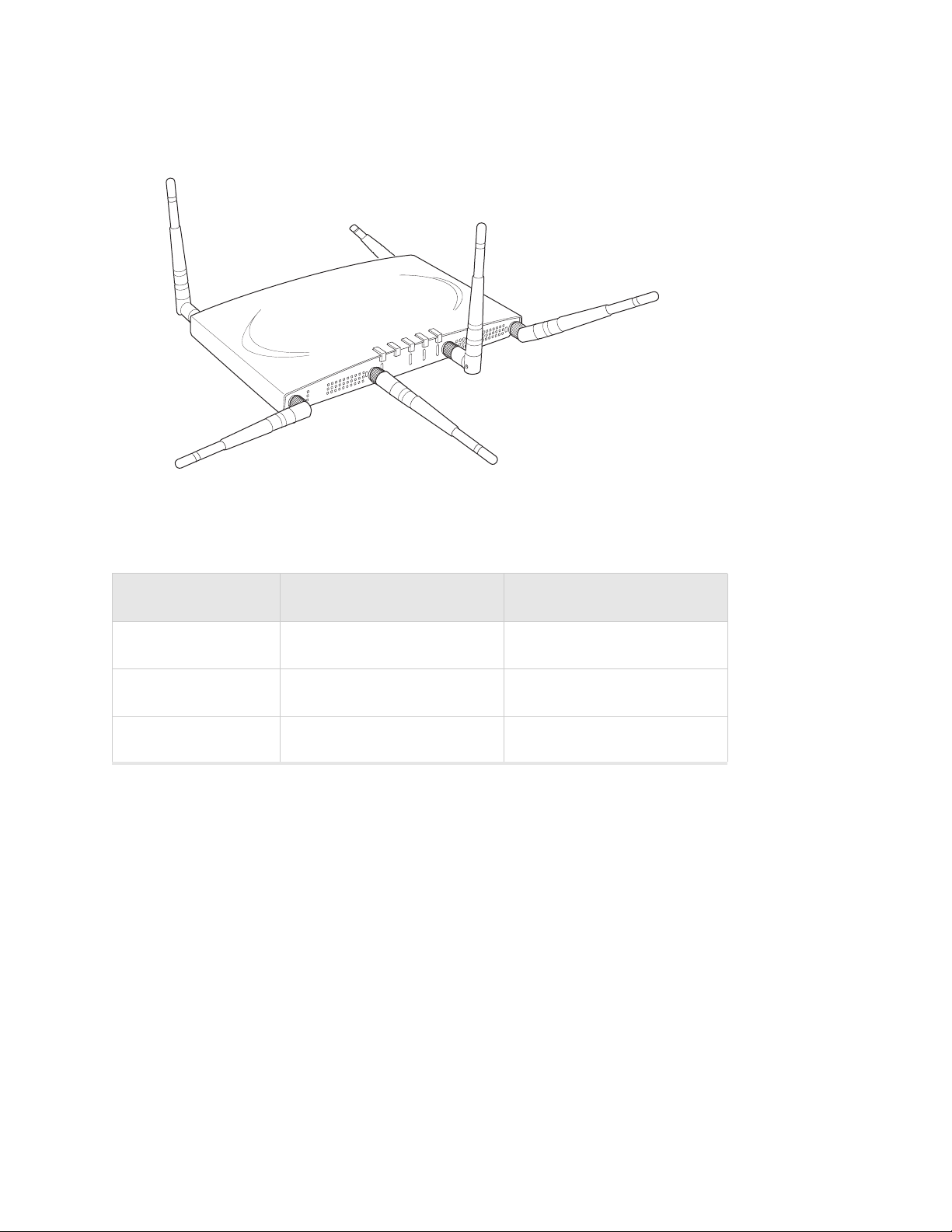
Figure 6: AP320, AP311 or AP302 Antennas 1-6
5
6
2
1
A
2
R
F
R
2
F
L
1
A
N
A
2
A
2
4
3
The following antenna connections are used during operation of the AP320, AP311, and AP302.
Table 5: Antenna Use for AP320, AP311, and AP302 (Dual Radio Units)
Mode Radio 1 Uses Radio 2 Uses
802.11abgn 3x3 MIMO Ant4, Ant5, Ant6 Ant1, Ant2, Ant3
802.11abgn 2x2 MIMO Ant4, Ant6 Ant1, Ant3
802.11abg Ant4 Ant1
The AP310 has six external antenna ports labeled 1 - 6. However, AP310 uses a maximum of three
antennas and the unused antenna connectors are blocked. Figure 7 illustrates the recommended
antenna configuration for the AP310.
© 2008 Meru Networks, Inc. Installing the AP300 16

Figure 7: AP310 Antennas 1-3
2
1
A
2
R
F
R
2
F
L
1
A
N
A
2
A
2
3
The following antenna connections are used during operation of the AP310.
Table 6: Antenna Use for AP310 (Single Radio Unit)
Mode Radio 1 Uses Radio2 Uses
802.11abgn 3x3 MIMO Ant1, Ant2, Ant3 NA
802.11abgn 2x2 MIMO Ant1, Ant3 NA
802.11abg Ant1 NA
The attached antennas must be the same model; if you replace one antenna, replace them all.
Attach the antennas to the connectors on the AP300 (see Figure 8). Rotate the knurled ring at the base
of the antenna clockwise to attach the antenna. The ring should be finger-tight.
Figure 8: AP300 Antenna Connection
antenna
connector
© 2008 Meru Networks, Inc. Installing the AP300 17

Caution!
When changing the orientation of the antennas, be sure to slightly loosen the
knurled ring before moving the antenna. Retighten the ring afterward. Otherwise, you
might damage the internal cabling in the AP.
Install the Optional Remote Antenna Mount on the Ceiling
Use an optional Remote Antenna Mount for one or both AP300 radios to remotely connect the AP300
antennas. The 3*3 SMA Antenna Stand allows you to relocate either your current antennas or the Meru's
High Gain Dipole Antennas to a location with clearer signal paths to the other devices in your wireless
network. The Remote Antenna Mount can be placed either below the ceiling tile or on the wall. The
default orientation for the Mount is suitable for a ceiling mount, but you can attach the Mount to a
wall with some modifications.
Use one mount per radio; for example AP310 needs one unit, and AP320 needs two units.The Antenna
Mount uses low-loss Plenum rated LMR195 cable and SMA connectors.
Figure 9: Remote Antenna Mount
The remote antenna mount kit includes:
z Antenna stand with attached cable. The three antenna SMA female connectors on the Antenna
Mount support AP300 antenna diversity. This feature gives the client the ability to automatically
choose the antenna receiving the strongest signal.
z Triangular ceiling mount clip for attaching to hanging ceiling (includes bolt assembly)
z Three self-adhesive pads for the bottom of the unit (over the screws)
z Two wall mount screws with anchors
z Ceiling Mount Template
z Installation diagram
© 2008 Meru Networks, Inc. Installing the AP300 18

To connect the remote antenna mount to the ceiling, refer to the enclosed installation diagram while
following these steps:
1. Attach the shorter end of the screw to the center hole on the back of the Antenna Mount.
2. Remove the designated ceiling tile.
3. Using the template, drill holes in the ceiling tile.
4. Replace the ceiling tile.
5. Remove a ceiling tile adjacent to the newly drilled tile for access purposes.
6. Feed the Antenna Mount cable through the larger hole in the ceiling tile until the Antenna Mount
is flush with the ceiling. The screw should now be visible above the ceiling tile (through the second
hole).
7. Place the triangular plate above the ceiling tile with the screw aligned through the plate.
8. Drop the washer onto the screw and tighten the bolt.
The Antenna Mount is now connected to the ceiling.
9. Replace the adjacent tile.
10. Connect the three Remote Antenna Mount cables to the appropriate connectors on the AP300. Be
sure to connect the three antennas that correspond to one radio. See Ta bl e 5 and Tab le 6 to
determine the cable connection configuration.
11. Attach three antennas that shipped with AP300 to the three connectors on the triangular remote
device. See Figure 9.
Install the Optional Antenna Mount on a Wall
1. Reorient the cable on the Remote Antenna Mount by removing the three screws on the back,
removing the small cover, reorienting the cable and then replacing the three screws. Discard the
small cover.
2. Connect the three Remote Antenna Mount cables to the appropriate connectors on the AP300. Be
sure to connect the three antennas that correspond to one radio. See Ta bl e 5 and Tab le 6 to
determine the cable connection configuration.
3. Attach three antennas that shipped with AP300 to the three connectors on the triangular remote
device. See Figure 9.
Install the Access Point
The AP300 ships with a detachable mounting bracket. The AP300 is designed to be compatible with
brackets supplied by Meru and by other vendors. The AP300 mounts directly on the AP150 mounting
bracket. If you are replacing AP300s, the AP300 bracket can be mounted on the old AP300 bracket with
included shoulder screws; you don’t need to remove the old brackets. AP300 can also be directly
mounted on third-party brackets. You can mount an AP300 in the following ways:
z Mount AP300 Horizontally on a Shelf
z Mount AP300 Vertically on a Wall
z Mount AP300 Below a Suspended Ceiling
z Mount AP300 Above a Suspended Ceiling (Plenum)
© 2008 Meru Networks, Inc. Installing the AP300 19

Mount AP300 Horizontally on a Shelf
When mounting an AP300 horizontally, remove the mounting bracket. Be sure to position the antennas
vertically when an AP300 sits on a surface. See Figure 1.
Mount AP300 Vertically on a Wall
Note:
same bracket. If you are replacing AP300s, the AP300 bracket can be attached to the old bracket with
included shoulder screws; you don’t have to remove the old brackets. This bracket will also mount
seamlessly into the Proxim AP4000 bracket and standard Cisco brackets.
To mount an AP300 on a wall:
1. Using the bracket holes as a guide, mark the location on the wall for the two AP bracket mounting
2. Drill holes at the locations you marked:
3. If you are using plastic anchors, install them in the holes.
4. Screw in the screws most of the way.
5. Mount the bracket on the screws, placing the circular portion of the keyhole mounts over the screw
6. Connect the Ethernet cable to the switch and to the AP300 Ethernet port shown in Figure 2.
7. If you are not using a PoE device, connect an external power supply to the power connector and
If you are replacing AP150s, you can use the existing brackets: the AP150 and AP300 use the
screws. If possible, center the mounting screws on a wall stud. If you do not center the mounting
screws on a wall stud, use plastic wall anchors.
— 3/16-inch holes if you are using plastic anchors
— 1/8-inch holes if you are using only the screws
heads and sliding the bracket down.
plug it into the wall.
Mount AP300 Below a Suspended Ceiling
The optional suspended ceiling mounting kit allows the AP300 mounting bracket to attach to suspended
ceiling T-rails (see Figure 10).
Note:
to the mounting bracket.
© 2008 Meru Networks, Inc. Installing the AP300 20
To comply with NEC code, attach a grounding wire to any of the screws used to attach the AP300

Figure 10: Mounting the AP300 to a Suspended Ceiling Rail
To mount an AP300 below a suspended ceiling:
1. Determine the location on the ceiling rail where the AP will be mounted and remove the ceiling
tiles.
2. Place each of the two caddy fasteners on the ceiling T-rail and twist to attach to the rail.
3. Adjust the distance between the caddy fasteners by using the mounting bracket holes as a guide.
4. Tighten the caddy fasteners in place using a standard screwdriver. Do not overtighten.
5. Place each spacer on the caddy fastener stud. The spacer legs should contact the ceiling T-rail.
6. Align the mounting bracket keyholes with the caddy fastener studs and slide the AP300 to the
narrow end of the hole.
7. Attach a keps nut to each caddy fastener stud and hand tighten. Do not overtighten.
8. Align the AP300 mounting posts over the circular portion of the keyhole mounts, push the AP in and
slide the AP down until it engages with the locking detents (see Figure 10). You should hear it snap
in place.
9. For each antenna, loosen the knurled ring at the base of the antenna (see Figure 8), orient the
antenna and then retighten the ring.
10. Connect one end of the PoE 100BaseT Ethernet cable to the 100/1000 Ethernet connector.
Caution!
Be sure to connect the Ethernet cable to the Ethernet port; the cable can
mistakenly be plugged into the Console port.
© 2008 Meru Networks, Inc. Installing the AP300 21

Mount AP300 Above a Suspended Ceiling (Plenum)
The optional T-bar box hanger mounting kit allows the AP300 to be mounted above suspended ceiling
T-rails (see Figure 11). The installation attaches the T-bar box hanger to the ceiling rails using clips.
The AP300 attaches to the mounting bracket that is attached to the T-bar box hanger.
The AP300 with the metal enclosure exposed meets the requirements for fire resistance and low
smoke-generating characteristics required by Section 300-22(C) of the National Electrical Code (NEC)
for installation in a building’s environmental air space.
You may need to modify thicker tiles to support this installation.
Warning!
When installed in air-handling spaces, such as above a suspended ceiling,
power the AP300 only with a PoE, not a power supply.
Warning!
Use Ethernet cable that meets the requirements for operating in plenums
and environmental air space (in accordance with Section 300-22(C) of the NEC).
Warning!
Any Fast Ethernet (FE) cables installed in air-handling spaces should be
suitable under NEC Article 800.50 and marked accordingly for use in plenums and airhandling spaces with regard to smoke propagation, such as CL2-P, CL3-P, MPP (Multi
Purpose Plenum), or CMP (Communications Plenum).
Figure 11: AP300 Mounted Above a Suspended Ceiling
Height adjustment screw
Access Point
Bracket mounting clip
Mounting bracket
T-bar hanger
Height adjustment screw
T-rail clips
Suspended ceiling T-rail
1. Determine the location on the ceiling rails where the AP will be mounted and remove the ceiling
tile.
2. Unpack the T-bar hanger kit and unfold the legs of the T-bar hanger.
© 2008 Meru Networks, Inc. Installing the AP300 22

3. Locate the bracket mounting clip holes on the mounting bracket (see Figure 11). One hole attaches
the bracket perpendicular to the box hanger; the other mounts the bracket parallel to the box
hanger.
4. Attach the U-joint of the clip to the T-bar and snap in place (see Figure 12).
Figure 12: Attaching the Mounting Bracket to the Box Hanger
.
00104
5. Pass the long end clip through the large center hole to the underside of the mounting bracket clip
and then attach the bracket to the clip using the supplied screw (see Figure 12 for orientation).
6. Hold the AP300 next to the mounting bracket to estimate the height of the T-bar box hanger to
provide enough clearance for the external antennas, which should be pointing down.
7. Adjust the height of the box hanger using the height adjusting screws (see Figure 10).
8. Clip the box hanger T-rail clips to the ceiling rails, making sure they are securely attached.
9. Connect a drop wire to a building structural element and through the hole provided in the bracket
mounting clip. The U.S. National Electrical Safety Code requires this additional support.
10. Connect the posts of the AP300 to the three keyholes of the mounting bracket and slide into the
keyhole, ensuring the locking detent is engaged. You will hear a click.
11. For each antenna, loosen the knurled ring at the base of the antenna (see Figure 8), point the
antenna down, then retighten the ring.
12. Connect one end of the PoE Ethernet cable to the Ethernet connector, shown in Figure 11.
13. Check that the AP300 is operating correctly before replacing the ceiling tile to the ceiling. Verify
correct operating using the LEDs, as shown in Check AP300 LED Activity.
Mount AP300 in a Hoffman Enclosure
To mount an AP300 in a Hoffman enclosure, follow these steps:
1. Place AP300 upside down on a soft flat surface.
2. Remove and discard the wall/ceiling mounting bracket (650-00064) if installed.
© 2008 Meru Networks, Inc. Installing the AP300 23

3. Remove and discard the four rubber feet.
4. If the unit has white antennas, remove them and attach the black antennas provided.
5. Position the Hoffman bracket (650-00128) onto the back of the AP300 with the four Hoffman
mounting screws facing downwards.
6. Using a Phillips screw driver, attach the bracket using the two supplied 6-32 3/16 SEMS screws (665-
00018).
7. Flip the assembly over and mount into the Hoffman enclosure, attach the Ethernet cable to the
AP300 rotating the assembly to allow ease of dressing the Ethernet cable within the enclosure.
8. Using a Phillips screw driver, tighten the four bracket screws to the enclosure.
9. Adjust the antennas as needed.
Check AP300 LED Activity
When the AP300 is first connects to the controller and any time the access point is rebooted, the AP
initializes with and then is programmed by the controller. When the AP is first powered up, all LEDs
are green. Thereafter, the Status LED color reflects the various operating states described in Ta bl e 7.
After the AP300 is connected, check the status of the LEDs.
Figure 13: AP300 Status LEDs
The functions of the five LEDs are described below.
A
2
R
F
R
2
F
L
1
A
S
N
T
A
P
T
W
R
A
3
S
L
P
T
W
A
R
T
R
A
F
N
1
R
F
2
00217
© 2008 Meru Networks, Inc. Installing the AP300 24

Table 7: AP300 LED Descriptions
LED Function
Check AP300 LED Activity
Power
Status
LAN
Radio 1
Radio 2
off—no power
green—presence of power
off—no power
green—booting stage 1
blinking green and off—booting stage 2
blinking green and white—discovering the controller
blinking green and blue—downloading a configuration from the
controller
blinking blue and off—AP is online and enabled, working state
blinking red and yellow—failure; consult controller for alarm state
off—no power or no link
green—link status OK (at any speed)
green/blinking—activity (at any speed)
red—auto negotiation failure
off—no radio present
green—radio enabled
green blinking—data activity
yellow—disabled or in scanning mode
red—failure
© 2008 Meru Networks, Inc. Installing the AP300 25

Check AP300 LED Activity
26 Meru AP300 Installation Guide © 2008 Meru Networks, Inc.

This chapter describes how to physically install the AP200. It contains the following
sections:
z Safety Precautions
z Unpacking the AP200
z Installation Requirements
z Installing the Access Points
z Where to Go From Here
z Checking LED Activity
Safety Precautions
Chapter 3
Installing the AP200
IMPORTANT—Read and follow the instructions in “Regulatory Information” on
page 115 before installing and operating this product.
Unpacking the AP200
As you unpack the AP200, confirm that the AP200 shipping package contains the items
listed on your packing list.
Shipments of the AP200 include a mounting bracket and mounting hardware for standard wall mounting. Optional mounting kits are available for mounting the AP200
above or below a hanging ceiling. The AP200 mounting studs are placed so they can
be used with brackets supplied by other vendors or to replace an AP100.
Note:
standard security cable, such as those used to secure laptop computers.
The AP200 has a security cable slot so you can secure the AP200 with a
© 2008 Meru Networks, Inc. Installing the AP200 27

Installation Requirements
Ceiling mount hole
A
W
S
c
An array of holes on the mounting bracket (see Figure 14) allows it to be mounted on
the wall and over junction boxes or molly bolts. There are also holes for passing the
PoE Ethernet or external power supply cable through the bracket if the bracket is
mounted on a junction box or over the ceiling T-bar box hanger.
all cable access
Access point mount
ccess point mount
uspended ceiling
able access
Figure 14: AP200 Mounting Bracket
Installation Requirements
The following recommended mounting locations provide the best reception for the
AP200:
Ceiling mount hole
Locking detent
Access point mount
00100
z On a horizontal surface, such as a table or a desk
z On a vertical surface, usually a wall
z Below a hanging ceiling
z Above a hanging ceiling tiles (this installation is supported only for the AP200 with
the plastic enclosure removed)
Warning!
With plastic covers removed, this product is suitable for use in
environmental air space in accordance with the Section 300-22(c) of the National
Electric Code and Sections 2- 128.12 - 010 (3) and 12 - 100 of the Canadian Electrical
Code. Part 1. C22. 1. For other countries, consult local authorities for regulations.
28 Meru Access Point and Radio Switch Installation Guide © 2008 Meru Networks, Inc.

Installation Requirements
To complete this installation, you need the items listed in Tabl e 8 .
Table 8: AP200 Installation Items
Installation Type Consumable Items Required
Horizontal mounting None
z Two #6 x 2" wood screws for a wood stud; or
Vertical mounting over a wall
stud
z Two #6 x 1½" metal screws for a metal stud
z Mounting bracket
z Two #6 x 1" screws
Vertical mounting on sheetrock
Horizontal mounting below a
hanging ceiling
Mounting above a ceiling tile
(AP200 metal enclosure only)
z Two #4-6 x 7/8" ribbed plastic wall anchors
z Mounting bracket
z Two caddy fasteners
z Two plastic spacers
z Two keps nuts (with attached lock washer)
z Mounting bracket
z Two T- ra il cl ip s
z One T-box hanger
z One bracket mounting clip
z Mounting bracket
© 2008 Meru Networks, Inc. Installing the AP200 29

Installing the Access Points
You need the tools listed in Tabl e 9 .
Table 9: AP200 Installation Tools
Installation Type Tools Required
Horizontal mounting None
Vertical mounting over a wall stud
z Drill
z 1/8"drill bit
z Screwdriver
z Drill
Vertical mounting on sheetrock
Horizontal mounting below a hanging ceiling
Mounting above a hanging ceiling (AP200
metal enclosure only)
Installing the Access Points
Selecting a Location
The AP200 requires a location that meets the following:
z Relatively unobstructed access to the stations the AP serves
z Power over Ethernet (PoE) connection to the network switch servicing the
controller.
z 3/16" drill bit
z Screwdriver
z Screwdriver
z Wrench or pliers
z Wrench or pliers
z Screwdriver
APs can obtain their power from 802.3af standard Power over Ethernet (PoE)-compatible network switch or PoE power injector installed between the switch and the
AP200.
Select a location with minimal physical obstructions between the AP and the wireless
stations. In an office with cubicles, mounting the APs below a hanging ceiling or the
wall near the ceiling provides the least obstructed communications path. For an
external power supply connection, ensure the power source is near to where the
AP200 will be mounted.
30 Meru Access Point and Radio Switch Installation Guide © 2008 Meru Networks, Inc.

Installing the Access Points
Most installations receive the best coverage using the following guidelines:
Install APs toward the center of the building.
z Do not install APs near metal objects, such as heating ducts, metal doors, or
electric service panels.
z Relative to the ground, orient the antenna up or down, not sideways.
Note:
environment. Place access points accordingly.
The AP200 is only intended for installation in Environment A as defined in IEEE
802.3af. All interconnected equipment must be contained within the same building,
including the interconnected equipment's associated LAN connection.
The previous guidelines are general guidelines. Each site has its own unique
Attaching the AP200 Antennas
The AP200 is provided with external antenna ports. Make sure that all external
antennas and their associated wiring are located entirely indoors. The external
antennas are not suitable for outside use.
If the AP200 does not have external antennas, attach the antennas to the connectors
on the AP200 (see Figure 15). Rotate the knurled ring at the base of the antenna
clockwise to attach the antenna. The ring should be finger-tight.
Caution!
the knurled ring before moving the antenna. Retighten the ring afterward.
Otherwise, you might damage the internal cabling in the AP.
When changing the orientation of the antennas, be sure to slightly loosen
Mounting the Access Point
You can mount an AP200 in the following ways:
z Horizontally, as described in the “Horizontal Mounting” section.
z Vertically, as described in the “Vertical Mounting” section.
z Below a hanging ceiling, as described in the “Mounting Below a Suspended
Ceiling” section.
z Above a tiled hanging ceiling, as described in the “Mounting Above a Suspended
Ceiling” section.
© 2008 Meru Networks, Inc. Installing the AP200 31

Installing the Access Points
A
00110
Horizontal Mounting
To horizontally mount an AP200:
1. Place the AP200 flat on the horizontal surface.
2. For each antenna, loosen the knurled ring at the base of the antenna (see
Figure 15), point the antenna straight up, then retighten the ring.
ntenna
ETHERNET
3.3 VDC
ANT 2
Turn clockwise
to tighten
Figure 15: AP200 Antenna Connection
3. Connect one end of the PoE 100BaseT Ethernet cable to the 100/1000 Ethernet
connector, shown in Figure 16.
For the AP201 and AP208 access points, a shielded Cat 5e (or greater)
Ethernet cable must be used in order to comply with international electro-
Note:
magnetic emissions limits.
If it is not practical to use shielded cables, contact Meru Support for a line
filter, available at no charge, that may also be used to ensure compliance.
Caution!
Be sure to connect the Ethernet cable to the Ethernet port; the cable can
mistakenly be plugged into the Console port (see Figure 16).
32 Meru Access Point and Radio Switch Installation Guide © 2008 Meru Networks, Inc.

Installing the Access Points
0
(Currently
Ceiling mount hole
A
W
S
c
(Reserved)
Antenna 1 Antenna 2
Console
port
ANT 1
CONSOLE
Reset
(Push to restore
default settings)
100/1000
Ethernet
ETHERNET
unsupported)
Power
inlet
3.3 VDC
ANT 2
0108
Figure 16: AP200 Connector Panel
Vertical Mounting
To vertically mount an AP:
1. Using the bracket holes as a template, mark the location on the wall for the two
AP bracket mounting screws. They are placed 4 ½ inches apart, center-to-center,
one above the other. If you are not using plastic wall anchors, you must center
the mounting screws on a wall stud. If you do not center the mounting screws on
a wall stud, you must use plastic wall anchors.
Access point mount
all cable access
ccess point mount
Locking detent
uspended ceiling
able access
Access point mount
Figure 17: AP200 Bracket
Ceiling mount hole
00100
© 2008 Meru Networks, Inc. Installing the AP200 33

Installing the Access Points
2. Drill holes at the locations you marked:
— 3/16-inch holes if you are using plastic anchors
— 1/8-inch holes if you are using only the screws
3. If you are using plastic anchors, install them in the holes.
4. Screw in the screws most of the way, so that the screw head is about 1/16 of an
inch from the wall.
5. Mount the bracket on the screws, placing the circular portion of the keyhole
mounts over the screw heads and sliding the bracket down.
6. Tighten the screws to secure the bracket.
7. Align the AP200 mounting posts over the circular portion of the keyhole mounts,
push the AP in and slide the AP down until it engages with the locking detents.
You should hear it snap in place.
Mounting bracket attached to wall
AP200
Figure 18: Aligning the AP200 with the Bracket
00115
34 Meru Access Point and Radio Switch Installation Guide © 2008 Meru Networks, Inc.

Installing the Access Points
Mounting bracket
00112
Figure 19: Sliding the AP200 into the Bracket
8. For external antennas, loosen the knurled ring at the base of each antenna (see
Figure 15), point the antenna straight up, then retighten the ring.
9. Connect one end of the PoE 100BaseT Ethernet cable to the 100/1000 Ethernet
connector, shown in Figure 16.
For the AP201 and AP208 access points, a shielded Cat 5e (or greater)
Ethernet cable must be used in order to comply with international electro-
Note:
magnetic emissions limits.
If it is not practical to use shielded cables, contact Meru Support for a line
filter, available at no charge, that may also be used to ensure compliance.
Caution!
Be sure to connect the Ethernet cable to the Ethernet port; the cable can
mistakenly be plugged into the Console port.
© 2008 Meru Networks, Inc. Installing the AP200 35

Installing the Access Points
Suspended ceiling T-rail
t
locking washer
s)
)
Mounting Below a Suspended Ceiling
The optional suspended ceiling mounting kit allows the AP200 mounting bracket to
attach to suspended ceiling T-rails (see Figure 20).
Note:
To comply with NEC code, attach a grounding wire to any of the screws used
to attach the AP200 to the mounting bracket.
Caddy fastener(
Plastic spacer(s
Mounting bracke
Keps nuts with attached
00102
Figure 20: Mounting the AP200 to a Suspended Ceiling Rail
To mount an AP200 below a suspended ceiling:
1. Determine the location on the ceiling rail where the AP will be mounted and
remove the ceiling tiles.
2. Place each of the two caddy fasteners on the ceiling T-rail and twist to attach to
the rail.
3. Adjust the distance between the caddy fasteners by using the mounting bracket
holes as a guide.
4. Tighten the caddy fasteners in place using a standard screwdriver. Do not
overtighten.
5. Place each spacer on the caddy fastener stud. The spacer legs should contact the
ceiling
T-rail.
6. Align the mounting bracket keyholes with the caddy fastener studs and slide the
AP200 to the narrow end of the hole.
7. Attach a keps nut to each caddy fastener stud and hand tighten. Do not
overtighten.
36 Meru Access Point and Radio Switch Installation Guide © 2008 Meru Networks, Inc.

Installing the Access Points
8. Align the AP200 mounting posts over the circular portion of the keyhole mounts,
push the AP in and slide the AP down until it engages with the locking detents
(see Figure 19). You should hear it snap in place.
9. For each antenna, loosen the knurled ring at the base of the antenna (see
Figure 15), point the antenna straight down, then retighten the ring.
10. Connect one end of the PoE 100BaseT Ethernet cable to the 100/1000 Ethernet
connector, shown in (see Figure 16).
For the AP201 and AP208 access points, a shielded Cat 5e (or greater)
Ethernet cable must be used in order to comply with international electro-
Note:
magnetic emissions limits.
If it is not practical to use shielded cables, contact Meru Support for a line
filter, available at no charge, that may also be used to ensure compliance.
Caution!
mistakenly be plugged into the Console port.
Be sure to connect the Ethernet cable to the Ethernet port; the cable can
Mounting Above a Suspended Ceiling
The optional T-bar box hanger mounting kit allows the AP200 to be mounted above
suspended ceiling T-rails (see Figure 21). The installation attaches the T-bar box
hanger to the ceiling rails using clips. The AP200 attaches to the mounting bracket
that is attached to the T-bar box hanger.
The AP200 antennas should point straight down for this type of installation. You may
need to modify thicker tiles to support this installation.
Warning!
the AP200 is to be powered via PoE only (PoE is required).
Warning!
fire resistance and low smoke-generating characteristics required by Section 30022(C) of the National Electrical Code (NEC) for installation in a building’s
environmental air space. You must remove the plastic enclosure to reveal the
plenum-rated AP200 metal case for installations above a suspended ceiling.
When installed in air-handling spaces, such as above a suspended ceiling,
The AP200 with the metal enclosure exposed meets the requirements for
Additionally, you must use Ethernet cable that meets the requirements for operating
in plenums and environmental air space (in accordance with Section 300-22(C) of the
NEC).
© 2008 Meru Networks, Inc. Installing the AP200 37

Installing the Access Points
w
Mounting bracket holes
Warning!
Any Fast Ethernet (FE) cables installed in air-handling spaces should be
suitable under NEC Article 800.50 and marked accordingly for use in plenums and airhandling spaces with regard to smoke propagation, such as CL2-P, CL3-P, MPP (Multi
Purpose Plenum), or CMP (Communications Plenum).
Height adjustment screw
Access Point 200
T-rail clips
Suspended ceiling T-rail
Bracket mounting clip
Mounting bracket
T-bar hanger
Height adjustment scre
Antennas
00103
Figure 21: Mounting the AP200 Above a Suspended Ceiling
To mount an AP200 above suspended ceiling rails:
1. Determine the location on the ceiling rails where the AP will be mounted and
remove the ceiling tile.
2. Unpack the T-bar hanger kit and unfold the legs of the T-bar hanger.
3. Locate the bracket mounting clip holes on the mounting bracket (see Figure 22).
One hole attaches the bracket perpendicular to the box hanger; the other mounts
the bracket parallel to the box hanger.
Figure 22: Box Hanger Mounting Bracket Holes
00101
38 Meru Access Point and Radio Switch Installation Guide © 2008 Meru Networks, Inc.

Installing the Access Points
4. Attach the U-joint of the clip to the T-bar and snap in place (see Figure 23).
.
00104
Figure 23: Attaching the Mounting Bracket to the Box Hanger
5. Pass the long end clip through the large center hole to the underside of the the
mounting bracket clip and then attach the bracket to the clip using the supplied
screw (see Figure 23 for orientation).
6. Hold the AP200 next to the mounting bracket to estimate the height of the T-bar
box hanger to provide enough clearance for the external antennas, which should
be pointing down.
7. Adjust the height of the box hanger using the height adjusting screws (see
Figure 20).
8. Clip the box hanger T-rail clips to the ceiling rails, making sure they are securely
attached.
9. Connect a drop wire to a building structural element and through the hole
provided in the bracket mounting clip. The U.S. National Electrical Safety Code
requires this additional support.
10. Connect the posts of the AP200 to the three keyholes of the mounting bracket and
slide into the keyhole (see Figure 19), ensuring the locking detent is engaged. You
will hear a click.
11. For each antenna, loosen the knurled ring at the base of the antenna (see
Figure 15), point the antenna down, then retighten the ring.
12. Connect one end of the PoE 100BaseT Ethernet cable to the 100/1000 Ethernet
connector, shown in Figure 16.
© 2008 Meru Networks, Inc. Installing the AP200 39

Where to Go From Here
Note:
For the AP201 and AP208 access points, a shielded Cat 5e (or greater)
Ethernet cable must be used in order to comply with international electromagnetic emissions limits.
If it is not practical to use shielded cables, contact Meru Support for a line
filter, available at no charge, that may also be used to ensure compliance.
Caution!
mistakenly be plugged into the Console port.
13. Check that the AP200 is operating correctly before replacing the ceiling tile to
the ceiling. Verify correct operating using the LEDs, as shown in Checking LED
Activity.
Be sure to connect the Ethernet cable to the Ethernet port; the cable can
Where to Go From Here
Now that the AP200 is installed, go to the Meru System Director Getting Started
Guide for instructions on initializing the controller and connecting the controller and
APs to the Ethernet switch to form the WLAN. Return to this chapter to check the
status of the LEDs once the WLAN is operational.
40 Meru Access Point and Radio Switch Installation Guide © 2008 Meru Networks, Inc.

Checking LED Activity
Access point status LEDs are provided on the Ethernet connector and on the face of
the AP200.
Ethernet Connector LEDs
After the AP200 is connected, the LEDs near the RJ-45 connector should light, as
shown in Figure 24.
Link present
Ethernet activity
Figure 24: RJ-45 LEDs
Checking LED Activity
00129
The green LED on the left blinks if any Ethernet activity is taking place. If there is
no Ethernet activity, the LED is off. The LED on the right is solid green if an Ethernet
link is present. If no Ethernet link is present or connectivity is lost, the LED is off.
© 2008 Meru Networks, Inc. Installing the AP200 41

Checking LED Activity
AP200 Status LEDs
Four status LEDs on the face of the AP200 also light, as shown in Figure 25.
. .
RF2
RF1
STATUS
POWER
AP200
00113
Figure 25: AP200 Status LEDs
The functions of the status LEDs are described in Tab l e 11.
When the AP200 is first connected to the controller and any time the access point is
rebooted thereafter, the AP initializes with and then is programmed by the
controller. When the AP is first powered up, all LEDs are green. Thereafter, the
Status LED (see Figure 25) color reflects the various operating states (Tabl e 1 1).
42 Meru Access Point and Radio Switch Installation Guide © 2008 Meru Networks, Inc.

Table 10: AP200 LED Descriptions
LED Function
The status LED for Radio 2 is a follows:
off—no radio present
RF 2
yellow—radio initializing
red—radio failure
solid green—radio OK
blinking green—radio activity
The status LED for Radio 1 is a follows:
off—no radio present
RF 1
yellow—radio initializing
red—radio failure
solid green—radio OK
blinking green—radio activity
Checking LED Activity
Status AP-Controller operational status (see Tab l e 1 1 )
Power green—presence of power
Table 11: AP200 Controller Status Information
State Interpretation AP200 LED Cycle
In the process of discovering the controller. The AP is connected but not
associated with the controller. If the
Attempting to discover Controller
AP does not associate with the control-
ler after a period of time, verify that
Green/Red/Blue/R
ed
the connection between the AP and the
switch or the switch and the controller
is unbroken.
Blue/Blue/Blue/R
Connected Normal operation without security.
ed
Blue/Blue/Blue/R
ed, for 2 seconds.
Authenticated Normal operation with security. Blue blink
© 2008 Meru Networks, Inc. Installing the AP200 43
a

Checking LED Activity
State Interpretation AP200 LED Cycle
Access point was once connected to a
Disconnected
controller and configured by the controller, but can no longer find that con-
Green/Purple/
Green/Purple
troller
Standalone
Downloading
Error State
a. The AP200 LEDs cycle from bright to dim for each “blink.”
Access point is operating in a standalone mode
Downloading image or configuration
from the controller
Access point is in an error state.
Call Meru technical support
Purple blink
Green/Blue
Green/Blue
Red (blinking or
solid)
44 Meru Access Point and Radio Switch Installation Guide © 2008 Meru Networks, Inc.

This chapter describes how to physically install the OAP180. It contains the following sections:
z Safety Precautions
z Unpacking the OAP180
z Installation Requirements
z Installing the Access Points
z Where to Go From Here
z Checking LED Activity
Safety Precautions
Chapter 4
Installing the OAP180
IMPORTANT—Read and follow the instructions in Appendix E, “Regulatory Information” on
page 115 before installing and operating this product.
This product is intended to be supplied by a UL Listed power supply, marked Class 2 or
LPS, and rated minimum 5 Vdc, 3A.
Caution!
installed in the plenum space.
The OAP180 is not certified for plenum installations, and should not be
© 2008 Meru Networks, Inc. Installing the OAP180 45

Unpacking the OAP180
00195
Unpacking the OAP180
Figure 26: OAP180 Outdoor Access Point
Top panel view Bottom panel view
2.4G 2.4G5G 5G
Console
Port Cover
Attachment
N-Type External
Antenna Connector
(5 GHz)
N-Type External
Antenna Connector
(2.4 GHz)
Confirm that the OAP180 shipping boxes contain the following items:
z OAP180 Outdoor Access Point
z Wall/Pole Mount Hardware Kit for mounting OAP180 to a 1.5” to 2” diameter steel pole
or tube or as part of a radio or tower structure
z N-Type Female connectors for external antennas
z Outdoor CAT5 Ethernet cable—100 feet. Be sure to include this (maximum) 100 foot
cable in link path calculation; the PoE does not resend the traffic, it only provides
power.
z Power injector with power cord
Installation Requirements
Console
Port
Console PoE
Ethernet/PoE
Connector
Water-Tight
Test Point
In addition to the hardware supplied by Meru Networks, you need the following:
Required
z Standard Ethernet cable to connect the power injector to a switch or controller
z Antennas (sold separately)
z Ground wire for the OAP180
Optional
z RF coaxial cable to connect the antenna to the OAP180
46 Meru Access Point and Radio Switch Installation Guide © 2008 Meru Networks, Inc.

Installing the Access Points
Selecting a Location
When you plan the OAP180 physical configuration, include the elements shown in this
drawing:
Installing the Access Points
External Antenna
Indoor Outdoor
LAN Switch
Ethernet Cable
Power Injector
Ground Wire
AC Power
Figure 27: Sample Physical Layout
RF Coaxial Cable
OAP 180
00196
Radio Position Planning
Never construct a radio mast, pole, or tower near overhead power lines. In addition, local
regulations may limit or prevent construction of a high radio mast or tower. If your
OAP180 link requires a high radio mast or tower, consult a professional contractor for
advice. Once the required antenna height has been determined, other factors affecting
the precise position of the OAP180 must be considered.
z Be sure there are no other radio antennas within 2 m (6 ft.) of the OAP180.
z Place the OAP180 away from power and telephone lines.
z Avoid placing the OAP180 too close to any metallic, reflective surfaces, such as roof-
installed air-conditioning equipment, tinted windows, wire fences, or water pipes.
Radio Interference
Avoiding radio interference is an important part of wireless planning. Interference is
caused by other radio transmissions using the same or an adjacent channel frequency. You
should first scan your proposed site using a spectrum analyzer to determine if there are
© 2008 Meru Networks, Inc. Installing the OAP180 47

Installing the Access Points
any strong radio signals using the 802.11a or 802.11bg channel frequencies. Always use a
channel frequency that is furthest away from another signal.
Weather Conditions
Take into account any extreme weather conditions that are known to affect your location. Consider these factors:
z Tem pe r a t u re — The OAP180 is tested for norma l operation in temperatures from - 40°F
to 140°F. Operating in temperatures outside of this range may cause the unit to fail.
z Wind Velocity — The OAP180 can operate in winds up to 44 m/s and survive higher wind
speeds up to 66 m/s. You must consider the known maximum wind velocity and
direction at the site and be sure that any supporting structure, such as a pole, mast,
or tower, is built to withstand this force.
z Lightning — The OAP180 includes its own built-in lightning surge protection. However,
you should make sure that the unit, any supporting structure, and cables are all
properly grounded. Additional protection using lightning rods, lightning arrestors, or
surge suppressors may also be employed. Antenna sockets should point upwards in a
vertical manner
z Rain — The OAP180 is weatherproofed against rain. Also, prolonged heavy rain has no
significant effect on the radio signal. However, it is recommended to apply
weatherproof sealing tape around the Ethernet port and antenna connectors for extra
protection. If moisture enters a connector, it may cause a degradation in performance
or even a complete failure of the link.
z Snow and Ice — Falling snow, like rain, has no significant effect on the radio signal.
However, a build up of snow or ice on antennas may cause the link to fail. In this case,
the snow or ice has to be cleared from the antennas to restore operation of the link.
Ethernet Cabling
When a suitable antenna location has been determined, plan a cable route from the
OAP180 outdoors to the power injector module indoors. Consider these points:
z The Ethernet cable length should never be longer than 100 ft.
z Determine a building entry point for the cable.
z Determine if conduits, bracing, or other structures are required for safety or protection
of the cable.
z For lightning protection at the power injector end of the cable, consider using a
lightning arrestor immediately before the cable enters the building.
z The shield of the ethernet cable needs to be grounded at the lightning arrestor. If, by
design, the lightning arrestor cannot provide this ground, the shield of the ethernet
cable will need to be grounded by the installer.
48 Meru Access Point and Radio Switch Installation Guide © 2008 Meru Networks, Inc.

Grounding
0
A
r
t
s
It is important that the OAP180, cables, and any supporting structures are properly
grounded. The OAP180 unit includes a grounding screw to attach a ground wire. Be sure
that grounding is available and that it meets local and national electrical codes.
Test Basic Link Operation
Set up the OAP180 on the ground, either outdoors or indoors. Connect the unit as indicated in this document and perform the basic configuration tasks outlined below.
When you are satisfied that the OAP180 is operating correctly, proceed to mounting the
unit in the intended location.
Mounting the Access Point
The OAP180 can be mounted on the following (brackets are included):
z 1.5 to 2 inch diameter pole
z Wall
Installing the Access Points
Mounting OAP180 with the Pole-Mounting Bracket
Follow these steps to mount the unit to a 1.5 to 2 inch diameter steel pole or tube using
the mounting bracket:
1. Attach the OAP180 to the mounting bracket.
Figure 28: Square Mounting Bracket Attaches to Bottom of OAP180
ttach the adjustable
ectangular plate to
he bridge with
upplied screws
0199
2. Place the V-shaped part of the bracket around the pole and tighten the securing nuts
just enough to hold the bracket to the pole. (The bracket may need to be rotated
around the pole during the alignment process.)
© 2008 Meru Networks, Inc. Installing the OAP180 49

Installing the Access Points
A
w
a
Note:
Always attach the bracket to a pole with the open end of the mounting grooves
facing up.
Figure 29: Brackets Attached to a Pole
ttach the bridge
ith bracket to
ffixed plate on pole
00201
3. Use the included nuts to tightly secure the wireless OAP180 to the bracket.
4. Connect the
OAP180 bracket and the pole bracket.
Mounting OAP180 with the Wall-Mounting Bracket
Attach the bracket to a wall with the flat side flush against the wall. Follow these steps
to mount the unit to a wall using the wall-mounting bracket:
1. Position the bracket in the intended location and mark the position of the four
mounting screw holes.
2. Drill holes in the wall that match the screws and wall plugs included in the bracket kit,
and then secure the bracket to the wall.
2
3. Use the included nuts to tightly secure the
4. Connect the two brackets as shown below.
OAP180 to the bracket.
50 Meru Access Point and Radio Switch Installation Guide © 2008 Meru Networks, Inc.

Connect Antennas and Ground Wire to OAP180
0
Nine antennas are supported for the OAP180. The supported antennas are:
z MN-ACC-ANT-BG08O-NM 802.11 b/g 8 dBi Omni-Directional Antenna, 2400 - 2500GHz (N
Male)
z MN-ACC-ANT-BG08O-NF 802.11 b/g 8 dBi Omni-Directional Antenna, 2400 - 2500GHz (N
Female)
z MN-ACC-ANT-BG18P-NF 802.11 b/g 18 dBi High Gain Panel Directional Antenna, 2400 -
2500GHz (N Female)
z MN-ACC-ANT-BG10S-NF 802.11 b/g 10 dBi High Gain Sector Antenna, 2400 - 2500GHz (N
Female)
z MN-ACC-ANT-A08O-NM-1 802.11a 8 dBi Omni-Directional Antenna, 5150 - 5350GHz (N
Male)
z MN-ACC-ANT-A08O-NM-2 802.11a 8 dBi Omni-Directional Antenna, 5470 - 5875GHz (N
Male)
z MN-ACC-ANT-A08O-NF 802.11a 8 dBi Omni-Directional Antenna, 4900 - 5350GHz (N
Female)
z MN-ACC-ANT-A23P-NF 802.11a 23 dBi High Gain Directional Panel, 5150 - 5875GHz (N
Female) *
z MN-ACC-ANT-A13S-NF 802.11a 13 dBi High Gain 120-degree Sector Antenna, 4900-
5150/5150-5875GHz (N Female)
Installing the Access Points
0203
* Not supported for the DFS bands 5.25 - 5.35 GHz and 5.47 - 5.725 GHz
The OAP180 works both with antennas that attach to the unit and remote antennas. When
using antennas that attach to the unit, attach the antenna before installing the unit. Use
the two connectors on the right (5G-1 and 2.4G-1) as indicated in Figure 8. When deploy-
© 2008 Meru Networks, Inc. Installing the OAP180 51

Installing the Access Points
5
C
ing an OAP180 with a remote antenna, first mount remote antennas and then connect
them to the OAP180.
Follow these steps:
1. Remove the two right-most antenna covers indicated in Figure 8.
2. Mount the external antenna on the same supporting structure as you did the OAP180,
within 3 m (10 ft.) of it, using the bracket supplied in the antenna package.
3. Connect the antenna to the OAP180’s N-type connector (5G-1 and 2.4G-1) using the
RF coaxial cable provided in the antenna box.
Figure 30: Connect the Antenna Cables
GHz N-type
onnector (5G-1)
2.4G-2
2.4 GHz N-type
Connector (2.4G-1)
5G-1
5 GHz External
High-gain Panel
Antenna
2.4G-15G-2
RF Coaxial
Cable
2.4 GHz External
Omnidirectional
Antenna
00204
4. Apply weatherproofing tape to the antenna connectors to help prevent water entering
the connectors.
Note:
When not using antenna connectors on the OAP180, keep the covers securely
attached for weather protection.
Follow these steps to attach the Ethernet cable and ground wire:
1. Using the included cable, attach the Ethernet cable to the Ethernet port on the
OAP180.
Note:
Use only the provided Ethernet cable. Do not shorten this cable as the path loss is
needed. During periods of lightning activity, do not connect or disconnect cables or
otherwise work with the OAP180.
52 Meru Access Point and Radio Switch Installation Guide © 2008 Meru Networks, Inc.

Console Port PoE (Ethernet) Port
E
C
Installing the Access Points
thernet
able
Console PoE
Ground Wire
00205
2. For extra protection against rain or moisture, apply weatherproofing tape (not
included) around the Ethernet connector.
3. Ground the unit with an appropriate grounding wire (not included) by attaching it to
the grounding screw on the unit. See above.
Caution!
Equipment shall be installed in accordance with the National Electrical Code
ANSI/NFPA 70 and the Canadian Electrical Code, Part 1, and when applicable, the National
Electrical Safety Code, IEEE C2.
Equipment shall be properly grounded according to Chapter 8 of ANSI/NFPA 70, the
National Electrical Code (NEC) and the Cable distribution system should be grounded
(earthed) in accordance with ANSI/NFPA 70, the National Electrical Code (NEC), in
particular Section 820.93, Grounding of the Outer Conductive Shield of a Coaxial Cable.
The separate protective earthing terminal provided on this product shall be permanently
connected to earth.
Caution!
Note:
Do not locate the power injector outdoors. The unit is for indoor use only.
The wireless Ethernet port does not support Power over Ethernet (PoE) based on
the IEEE 802.3af standard. Do not try to power the unit by connecting it directly to a
network switch that provides IEEE 802.3af PoE. Always connect the unit to the included
power injector module to maintain the warranty.
Note:
Each AC power injector requires 1.5 amps of power at 100-240 volts. When
connecting multiple devices to one outlet, be sure to allow 1.5 amps for each AC power
adapter.
© 2008 Meru Networks, Inc. Installing the OAP180 53

Installing the Access Points
Follow these steps to connect the power injector:
1. Connect the other end of the provided Ethernet cable (already connected to the
OAP180) to the RJ-45 port labeled Output on the power injector.
Ethernet cable
from LAN switch
Power LED indicator
Ethernet cable to
wireless bridge
AC power
00206
2. Connect a straight-through unshielded twisted-pair (UTP) cable (not included) from a
Note:
computer for testing the link, use a crossover cable.
3. Insert the power cable plug directly into the standard AC receptacle on the power
4. Plug the other end of the power cable into a grounded, 3-pin socket, AC power source.
Note:
line cord set that has been approved for the receptacle type in your country.
5. Check the LED on top of the power injector to be sure that power is being supplied to
Align Antenna
After the OAP180 unit is mounted, connected, and the radios are operating, the antennas must be accurately aligned to ensure optimum performance of the OAP180 links. In
local LAN switch to the RJ-45 port labeled Input on the power injector. See the
illustration above. Use Category 5e or better UTP cable for 10/100BASE-TX
connections.
The RJ-45 port on the power injector is an MDI port. If connecting directly to a
injector. See the illustration above.
For International use, you may need to change the AC line cord. You must use a
the OAP180 through the Ethernet connection.
54 Meru Access Point and Radio Switch Installation Guide © 2008 Meru Networks, Inc.

this point-to-multipoint configuration all OAP180 nodes must be aligned with the root
OAP180 antenna.
Where to Go From Here
Now that the OAP180 is installed, go to the Meru System Director Getting Started Guide
for instructions on initializing the controller and connecting the controller and APs to the
Ethernet switch to form the WLAN. Return to this chapter to check the status of the LEDs
once the WLAN is operational.
As well, check the AP chapter in the Meru System Director Configuration Guide for
instructions on configuring radio band, dual radio, and external antenna operation.
Checking LED Activity
Where to Go From Here
Check the OAP180 LEDs for activity. Four of the eight LEDs on the bottom of the OAP180
indicate activity; four LEDs are not used at this time. Check the four active LEDs to determine if the AP is working.
Console PoE
Power On
LED
ese 4 LEDs
e not used
Transmission LEDs
(radio packets transmitting)
Ethernet link
LED
00194
© 2008 Meru Networks, Inc. Installing the OAP180 55

Checking LED Activity
Figure 31: OAP180 LEDs
The grey LEDs in the illustration are not currently used. The following chart explains the
meanings for the remaining LEDs.
LED Function
When power is applied, this LED initially turns amber, then blinks
Power
green when the system power check is applied, and then is a steady
green when power is on.
Radio 1
802.11bg
Radio 2
802.11a
Ethernet
The 11bg connection LED blinks amber when radio packets are
being transmitted and when the radio is beaconing. If there is traffic
over the air on this radio, the blinking rate increases.
The 11a connection LED blinks green when radio packets are being
transmitted and when the radio is beaconing. If there is traffic over
the air on this radio, the blinking rate increases.
The Ethernet Link LED blinks green when a link has been detected
and is in use.
Antenna Gain Recommendations
The OAP180 auto-adjusts the power level sent from the radio to the antenna, so that the
EIRP emitted from the antenna is the value defined by the controller (100mW by default).
You can increase this setting if you are compensating for signal loss from long inexpensive
cables connecting external antennas. (Configure a false/low dBi antenna gain to trick the
radio into supplying more transmit power to that antenna, which would then make up for
the cable loss.) You may also need to decrease the EIRP from 100mW to 30mW for a
device that only transmits at 30mW. The Antenna Gain values can be changed from the
Web UI Configuration>APs>Antenna Properties view, or from the CLI using the antenna-
property command. Determine the appropriate gain for your antenna by checking the
following chart.
56 Meru Access Point and Radio Switch Installation Guide © 2008 Meru Networks, Inc.

Table 12: Antenna Gain
Antenna Gain
Checking LED Activity
MN-ACC-ANT-BG08O-NM 802.11 b/g 8 dBi OmniDirectional Antenna, 2400 - 2500GHz (N Male)
MN-ACC-ANT-BG08O-NF 802.11 b/g 8 dBi OmniDirectional Antenna, 2400 - 2500GHz (N Female)
MN-ACC-ANT-BG18P-NF 802.11 b/g 18 dBi High
Gain Panel Directional Antenna, 2400 - 2500GHz
(N Female)
MN-ACC-ANT-BG10S-NF 802.11 b/g 10 dBi High
Gain Sector Antenna, 2400 - 2500GHz (N Female)
MN-ACC-ANT-A08O-NM-1 802.11a 8 dBi OmniDirectional Antenna, 5150 - 5350GHz (N Male)
MN-ACC-ANT-A08O-NM-2 802.11a 8 dBi OmniDirectional Antenna, 5470 - 5875GHz (N Male)
MN-ACC-ANT-A08O-NF 802.11a 8 dBi OmniDirectional Antenna, 4900 - 5350GHz (N Female)
8
8
18
10
8
8
8
MN-ACC-ANT-A23P-NF 802.11a 23 dBi High Gain
Directional Panel, 5150 - 5875GHz (N Female)
MN-ACC-ANT-A13S-NF 802.11a 13 dBi High Gain
23
12.5/13.5
120-degree Sector Antenna, 4900-5150/51505875GHz (N Female)
© 2008 Meru Networks, Inc. Installing the OAP180 57

Checking LED Activity
58 Meru Access Point and Radio Switch Installation Guide © 2008 Meru Networks, Inc.

This chapter describes how to physically install the AP150. It contains the following
sections:
z Safety Precautions
z Unpacking the AP150
z Installation Requirements
z Installing the Access Points
z Where to Go From Here
z Checking LED Activity
Safety Precautions
Chapter 5
Installing the AP150
IMPORTANT—Read and follow the instructions in Appendix E, “Regulatory Information” on page 115 before installing and operating this product.
This product is intended to be supplied by a UL Listed power supply, marked Class 2
or LPS, and rated minimum 5 Vdc, 3A.
Caution!
installed in the plenum space.
The AP150 is not certified for plenum installations, and should not be
Unpacking the AP150
Confirm that the AP150 shipping package contains the AP150 access point with
attached mounting bracket
© 2008 Meru Networks, Inc. Installing the AP150 59

Installation Requirements
Figure 32: AP150 with Mounting Bracket
Installation Requirements
If you choose not to use the AP150 mounting bracket, the backside of the AP150
contains two keyholes to accommodate a simple wall mount.
A mounting bracket can be used for many wall mounting configurations. The AP150
bracket mounting studs are placed so they can be used with brackets supplied by
other vendors or to replace an AP100. An array of holes on the mounting bracket (see
Figure 32) allow it to be mounted on the wall and over junction boxes or molly bolts.
There are also holes for passing the PoE Ethernet or external power supply cable
through the bracket if the bracket is mounted on a junction box.
00177
Additional optional mounting kits are available for mounting the AP150below a
hanging ceiling, using the mounting bracket.
60 Meru Access Point and Radio Switch Installation Guide © 2008 Meru Networks, Inc.

Installation Requirements
Caution!
The AP150 is not certified for plenum installations, and should not be
installed in the plenum space.
Note:
The AP150 has two security cable slots (one on each side of the AP150) so you
can secure the AP150 with a standard security cable, such as those used to secure
laptop computers.
The following recommended mounting locations provide the best reception for the
AP150:
z On a horizontal surface, such as a table or a desk
z On a vertical surface, usually a wall
z Below a hanging ceiling
To complete this installation, you need the items listed in Tabl e 1 3 .
Table 13: AP150 Installation Items
Installation Type Consumable Items Required
Horizontal mounting None
Vertical mounting over a wall
stud
Vertical mounting on sheetrock
Horizontal mounting below a
hanging ceiling
z Two #6 x 2" wood screws for a wood stud; or
z Two #6 x 1½" metal screws for a metal stud
z Mounting bracket
z Two #6 x 1" screws
z Two #4-6 x 7/8" ribbed plastic wall anchors
z Mounting bracket
z Two caddy fasteners
z Two plastic spacers
z Two keps nuts (with attached lock washer)
z Mounting bracket
© 2008 Meru Networks, Inc. Installing the AP150 61

Installing the Access Points
You need the tools listed in Tabl e 1 4.
Table 14: AP150 Installation Tools
Installation Type Tools Required
Horizontal mounting None
Vertical mounting over a wall
stud
Vertical mounting on sheetrock
z Drill
z 1/8"drill bit
z Screwdriver
z 1/8"Allen wrench
z Drill
z 3/16" drill bit
z Screwdriver
z 1/8"Allen wrench
z Screwdriver
Horizontal mounting below a
hanging ceiling
z Wrench or pliers
z 1/8"Allen wrench
Installing the Access Points
Selecting a Location
The AP150 requires a location that meets the following:
z Relatively unobstructed access to the stations the AP serves
z Power over Ethernet (PoE) connection to the network switch servicing the
controller.
APs can obtain their power from 802.3af standard Power over Ethernet (PoE)-compatible network switch or PoE power injector installed between the switch and the
AP150.
Select a location with minimal physical obstructions between the AP and the wireless
stations. In an office with cubicles, mounting the APs below a hanging ceiling or the
wall near the ceiling provides the least obstructed communications path.
62 Meru Access Point and Radio Switch Installation Guide © 2008 Meru Networks, Inc.

Installing the Access Points
Most installations receive the best coverage using the following guidelines:
Install APs toward the center of the building.
z Do not install APs near metal objects, such as heating ducts, metal doors, or
electric service panels.
z Relative to the ground, orient the antenna up or down, not sideways.
Note:
environment. Place access points accordingly.
The AP150 is only intended for installation in Environment A as defined in IEEE
802.3af. All interconnected equipment must be contained within the same building,
including the interconnected equipment's associated LAN connection.
The previous guidelines are general guidelines. Each site has its own unique
Attaching the AP150 Antennas
The AP150 is provided with external antenna ports. Make sure that all external
antennas and their associated wiring are located entirely indoors. The external
antennas are not suitable for outside use.
If the AP150 does not have external antennas, attach the antennas to the connectors
on the AP150 (see Figure 33). Rotate the knurled ring at the base of the antenna
clockwise to attach the antenna. The ring should be finger-tight.
Caution!
the knurled ring before moving the antenna. Retighten the ring afterward.
Otherwise, you might damage the internal cabling in the AP.
When changing the orientation of the antennas, be sure to slightly loosen
Mounting the Access Point
You can mount an AP150 in the following ways:
z Horizontally, as described in the “Horizontal Mounting” section.
z Vertically, as described in the “Vertical Mounting with the Mounting Bracket”
section.
z Below a hanging ceiling, as described in the “Mounting Below a Suspended
Ceiling” section.
Horizontal Mounting
To horizontally mount an AP150:
1. Place the AP150 flat on the horizontal surface.
2. For each antenna, loosen the knurled ring at the base of the antenna (see
Figure 33), point the antenna straight up, then retighten the ring.
© 2008 Meru Networks, Inc. Installing the AP150 63

Installing the Access Points
A
Antenna 1 Antenna 2
ntenna
RESET
RELOAD
ANT 2
Turn clockwise
00172
to tighten
Figure 33: AP150 Antenna Connection
3. Connect one end of the PoE 100BaseT Ethernet cable to the 100/1000 Ethernet
connector, shown in Figure 34.
Console
Power Ethernet
(reserved)
ANT1 ANT2
DC 5V
connection
LAN
port
(reserved)
CONSOLE
Reset
Reload
button
RESET RELOAD
0173
Figure 34: AP150 Connector Panel
Vertical Mounting the AP150
To perform a simple wall mount using the keyholes on the back of the AP150:
1. Remove the attached mounting bracket from the back of the AP150.
2. Mark the location on the wall for two mounting screws. They are placed 4.3"
apart, center-to-center, or one above the other. If you are not using plastic wall
anchors, you must either center the mounting screws on a wall stud or use plastic
wall anchors.
3. Drill holes at the locations you marked:
— 3/16-inch holes if you are using plastic anchors
— 1/8-inch holes if you are using only the screws
64 Meru Access Point and Radio Switch Installation Guide © 2008 Meru Networks, Inc.

Installing the Access Points
4. If you are using plastic anchors, install them in the holes.
5. Screw in the screws most of the way, so that the screw head is about 1/16 of an
inch from the wall.
6. Align the AP150 keyholes over the mounting screws and slightly pull down (or
across, if mounting sideways).
7. For external antennas, loosen the knurled ring at the base of each antenna (see
Figure 33), point the antenna straight up, then retighten the ring.
8. Connect one end of the PoE 100BaseT Ethernet cable to the 100/1000 Ethernet
connector, shown in Figure 34.
Vertical Mounting with the Mounting Bracket
The AP150 uses thumbscrews to attach to the mounting bracket or mounting plate
that allows the access point to be mounted on a vertical surface. Additionally, three
shoulder screws may be installed on the mounting bracket to allow the AP150 and
attached bracket to mount over a previously installed Cisco 1200 mounting bracket.
To vertically mount an AP:
1. If not mounting the AP150 to a previously third-party installed mounting bracket,
use a 1/8" Allen wrench to remove the shoulder screws from the mounting
bracket, if already attached.
2. Using the bracket holes as a template, remove the bracket from the AP150 (or use
the stencil in Appendix C, “Mounting Bracket Stencils”) to mark the location on
the wall for the two AP bracket mounting screws. They are placed 4.3 inches
apart, center-to-center. If you are not using plastic wall anchors, you must center
the mounting screws on a wall stud. If you do not center the mounting screws on
a wall stud, you must use plastic wall anchors.
© 2008 Meru Networks, Inc. Installing the AP150 65

Installing the Access Points
00167
Suspended ceiling
cable access
Wall cable access
Figure 35: AP150 Bracket
3. Drill holes at the locations you marked:
— 3/16-inch holes if you are using plastic anchors
— 1/8-inch holes if you are using only the screws
4. If you are using plastic anchors, install them in the holes.
5. Screw in the screws most of the way, so that the screw head is about 1/16 of an
inch from the wall.
6. Mount the bracket on the screws, placing the circular portion of the keyhole
mounts over the screw heads and sliding the bracket down.
7. Tighten the screws to secure the bracket.
8. Align the AP150 with the bracket thumbscrews (see Figure 36) and tighten the
thumbscrews to attach the bracket.
66 Meru Access Point and Radio Switch Installation Guide © 2008 Meru Networks, Inc.

Installing the Access Points
00169
Figure 36: Aligning the AP150 with the Bracket
9. For external antennas, loosen the knurled ring at the base of each antenna (see
Figure 33), point the antenna straight up, then retighten the ring.
10. Connect one end of the PoE 100BaseT Ethernet cable to the 100/1000 Ethernet
connector, shown in Figure 34.
© 2008 Meru Networks, Inc. Installing the AP150 67

Installing the Access Points
Suspended ceiling T-rail
t
s)
Mounting Below a Suspended Ceiling
The optional suspended ceiling mounting kit allows the AP150 mounting bracket to
attach to suspended ceiling T-rails (see Figure 37).
Note:
To comply with NEC code, attach a grounding wire to any of the screws used
to attach the AP150 to the mounting bracket.
Caddy fastener(
Spacer(s)
Mounting bracke
Washers
00170
Figure 37: Mounting the AP150 to a Suspended Ceiling Rail
To mount an AP150 below a suspended ceiling:
1. Using a 1/8" Allen wrench, remove the shoulder screws from the mounting
bracket, if already attached.
2. Determine the location on the ceiling rail where the AP will be mounted and
remove the ceiling tiles.
3. Place each of the two caddy fasteners on the ceiling T-rail and twist to attach to
the rail.
4. Adjust the distance between the caddy fasteners by using the mounting bracket
holes as a guide.
5. Tighten the caddy fasteners in place using a standard screwdriver. Do not
overtighten.
6. Place each spacer on the caddy fastener stud. The spacer legs should contact the
ceiling T-rail.
7. Align the mounting bracket keyholes with the caddy fastener studs and slide the
AP150 to the narrow end of the hole.
68 Meru Access Point and Radio Switch Installation Guide © 2008 Meru Networks, Inc.

8. Attach a keps nut to each caddy fastener stud and hand tighten. Do not
overtighten.
9. Align the AP150 with the bracket thumbscrews (see Figure 36) and tighten the
thumbscrews to attach the bracket.
10. For each antenna, loosen the knurled ring at the base of the antenna (see
Figure 33), point the antenna straight down, then retighten the ring.
11. Connect one end of the PoE 100BaseT Ethernet cable to the 100/1000 Ethernet
connector, shown in (see Figure 34).
Where to Go From Here
Now that the AP150 is installed, go to the Meru System Director Getting Started
Guide for instructions on initializing the controller and connecting the controller and
APs to the Ethernet switch to form the WLAN. Return to this chapter to check the
status of the LEDs once the WLAN is operational.
Where to Go From Here
© 2008 Meru Networks, Inc. Installing the AP150 69

Checking LED Activity
Checking LED Activity
Access point status LEDs are provided on the Ethernet connector and on the face of
the AP150.
AP150 Status LEDs
Four status LEDs on the face of the AP150 also light, as shown in Figure 38.
.
PW
R
RADIO1
RADIO2
LA
N
00166
Status LEDs
Figure 38: AP150 Status LEDs
When the AP150 is first connected to the controller and any time the access point is
rebooted thereafter, the AP initializes with and then is programmed by the
controller. The Status LED (see Figure 38) color reflects the various operating states
(Ta b l e 15).
70 Meru Access Point and Radio Switch Installation Guide © 2008 Meru Networks, Inc.

Table 15: AP150 LED Descriptions
LED Function
The Power status LED status is as follows:
z off—power is off
z solid red—when power is applied, system initializes for 40 sec-
onds and then the LED turns amber; after discovering the con-
Power
troller the LED turns green. Otherwise, the system is in an
abnormal state (notify Customer Support).
z solid amber—at any time, if this LED state persists longer than 40
seconds, notify Customer Support
z solid green—system is fully operational
Checking LED Activity
Radio I
Radio II
Ethernet
The Radio I LED is lit when radio packets are being transmitted and
when the radio is beaconing.
The Radio II LED is lit when radio packets are being transmitted and
when the radio is beaconing.
The Ethernet LED status is as follows:
z off—no link
z solid green—100Mbps connection
z blinking green—transmit or receive activity at 100Mbps
z solid amber—10Mbps connection
z blinking amber—transmit or receive activity at 10Mbps
© 2008 Meru Networks, Inc. Installing the AP150 71

Checking LED Activity
72 Meru Access Point and Radio Switch Installation Guide © 2008 Meru Networks, Inc.

This chapter describes how to physically install the Meru Radio Switch RS4000. It
contains the following sections:
z Safety Precautions
z Unpacking the RS4000
z Installation Requirements
z Installing the RS4000
z Where to Go From Here
z Checking LED Activity
Safety Precautions
Chapter 6
Installing the RS4000
IMPORTANT—Read and follow the instructions in Appendix E, “Regulatory Informa-
tion” on page 115 before installing and operating this product.
Unpacking the RS4000
Confirm that the RS4000 shipping package contains the following items:
z RS4000
z 180-degree directional antenna or omni-directional antenna
z Two 3-foot antenna cables
z One 3-inch mounting arm (includes wall mount base and ceiling rail base)
z Mounting bracket
z Additional options can be purchased, such as a NEMA box mounting bracket and
6-foot antenna cables
© 2008 Meru Networks, Inc. Installing the RS4000 73

Installation Requirements
ER
POW
RADIO I
RADIO II
ETHERNET
RS4000Antenna
Wall mounting bracket 3-inch mounting arm with
Figure 39: RS4000 Package Contents
Installation Requirements
The following prerequisites and system requirements must be met:
z 2 IEEE 802.3 PoE connections— one to each Ethernet port, yielding a maximum
power specification of 11W per port, 22W total for the RS4000
z Network switch for connecting all networking components
The RS4000 requires a location that meets the following:
wall mounting base
Ceiling rail
mounting
base
00193
z A location to mount the antenna within 6’ of the RS4000 and with relatively
unobstructed access to the client stations
z Power over Ethernet (PoE) connection to the network switch servicing the RS4000
74 Meru Access Point and Radio Switch Installation Guide © 2008 Meru Networks, Inc.

Installation Requirements
The RS4000 obtains power from 802.3af standard Power over Ethernet (PoE)-compatible network switch or PoE power injector installed between the switch and the
RS4000. At least one PoE connection must be connected.
Select a location with minimal physical obstructions between the RS4000 antenna
and the wireless stations. In many cases, mounting the RS4000 antenna on the wall
near the ceiling provides the least obstructed communications path.
Most installations receive the best coverage using the following guidelines:
z Do not install the antenna near metal objects, such as heating ducts, metal doors,
or electric service panels.
z Relative to the ground, orient the antenna up or down, not sideways.
Note:
The previous guidelines are general guidelines. Each site has its own unique
environment. Place antenna accordingly.
The RS4000 is only intended for installation in Environment A as defined in IEEE
802.3af. All interconnected equipment must be contained within the same building,
including the interconnected equipment's associated LAN connection.
© 2008 Meru Networks, Inc. Installing the RS4000 75

Installation Requirements
You need the tools listed in Tabl e 1 6.
Table 16: RS4000 Installation Tools
Installation Type Tools Required
Vertical mounting over a wall
stud
Vertical mounting on sheetrock
Horizontal mounting below a
hanging ceiling
z Drill
z 1/8"drill bit
z Screwdriver
z (Optional) Pliers
z Drill
z 3/16" drill bit
z Screwdriver
z (Optional) Pliers
z Two caddy fasteners
z Two plastic spacers
z Two keps nuts (with attached lock washer)
z Mounting bracket
z Two T- ra il cl ip s
z One T-box hanger
Mounting above a ceiling tile
z One bracket mounting clip
z Mounting bracket
About an Hoffman/NEMA Enclosure Installation
The recommended RS4000 installation is a wall mount, but if necessary the RS4000
can be housed inside a protective NEMA or Hoffman box that is manufactured with
external corner tabs for standard wall mounting, above or below a ceiling. When
installing in the Hoffman/NEMA box, the RS4000 attaches to an optional
Hoffman/NEMA box mounting plate, which replaces the standard wall mount bracket.
Caution!
Laboratories.
Meru leaves the placement and orientation of the Hoffman/NEMA enclosure to the
customer. It will be necessary to drill holes through the plastic NEMA enclosure with
a Meru-provided template to enable the antenna and Ethernet cabling to exit the
enclosure. Instructions for performing this task are provided in the section “Creating
This method of mounting has not been evaluated by Underwriters
76 Meru Access Point and Radio Switch Installation Guide © 2008 Meru Networks, Inc.

Installation Requirements
NEMA box
s
Cable Pass-through Holes in the NEMA Enclosure” on page 89. To install in the
Hoffman/NEMA Enclosure, see the section “Hoffman/NEMA Enclosure RS4000 Installation” on page 89.
Attach to wall with 4 screw
00187
Figure 40: Open NEMA Box Showing Mounting Holes
Optimum Antenna Positioning and Placement
Warning!
cm. (~ 8 in.) from all users and bystanders. For the protection of personnel working
in the vicinity of inside (downlink) antennas, the following guidelines for minimum
distances between the human body and the antenna must be observed.
The installation of the indoor antenna must be such that, under normal conditions,
all personnel cannot come within 20 cm. (~ 8.0 in.) from any inside antenna.
Exceeding this minimum separation will ensure that the employee or bystander does
not receive RF-exposure beyond the Maximum Permissible Exposure according to FCC
CFR 47, section 1.1310 i.e. limits for General Population/Uncontrolled Exposure.
Inside antennas must be positioned to observe minimum separation of 20
© 2008 Meru Networks, Inc. Installing the RS4000 77

Installing the RS4000
Installing the RS4000
Mounting the RS4000
You can mount the RS400 in the following ways:
z Wall Mounting the RS4000
z Mounting Below a Suspended Ceiling
z Mounting Above a Suspended Ceiling
z Placing and Positioning the Antenna
z Hoffman/NEMA Enclosure RS4000 Installation
Wall Mounting the RS4000
The RS4000 can be mounted to any type of solid wall (including ceiling walls) using
the supplied wall mount bracket. The bracket also allows for junction box mounting.
Note:
standard security cable (for example, Kensington cable locks), such as are used to
secure laptop computers.
To wall mount an RS4000:
1. Remove the bracket from back side the RS4000, if it is attached, by unscrewing
The RS4000 has a security cable slot so you can secure the RS4000 with a
each of the 4 knurled thumbscrews (see Figure 41).
78 Meru Access Point and Radio Switch Installation Guide © 2008 Meru Networks, Inc.

Installing the RS4000
Figure 41: Bracket Attached to RS4000
2. Choose the location on the wall where the RS4000 will be mounted. The RS4000
can be oriented in any direction, but it is probably more convenient if the SMA
antenna mounts are at the top. This orientation is more convenient for reading
LED status.
3. Using the bracket holes as a template, mark the location on the wall for the two
RS4000 bracket mounting screws. They are placed 5 25/32" (147mm) apart,
center-to-center, one above the other. If you are not using plastic wall anchors,
you must center the mounting screws on a wall stud.
Note:
The RS4000 mounting bracket provides holes to accommodate many types of
common installations such as over a junction box, etc. This procedure describes only
the standard wall mount.
4. Drill holes at the locations you marked:
— 3/16-inch holes if you are using plastic anchors
— 1/8-inch holes if you are using only the screws
5. If you are using plastic anchors, install them in the holes.
© 2008 Meru Networks, Inc. Installing the RS4000 79

Installing the RS4000
Wall mounting bracket
6. Screw in the screws most of the way, so that the screw head is about 1/16 of an
inch from the wall.
7. Mount the bracket on the screws, placing the circular portion of the keyhole
mounts over the screw heads and sliding the bracket down.
(attached to wall)
Captive screws (4)
RS4000
POWER
RADIO I
RADIO II
ETHERNET
00186
Figure 42: RS4000 Bracket Mounting
8. Tighten the bracket captive screws to secure the RS4000 to the bracket.
9. On the RS4000, attach the two antenna cables to the SMA antenna connectors
80 Meru Access Point and Radio Switch Installation Guide © 2008 Meru Networks, Inc.
the cable ends clockwise until tight.
labeled
ANT1 and ANT2 on the top panel of the RS4000 (see Figure 43) by turning

(Meru logo is upside down)
Installing the RS4000
ANT1 ANT2
ETH1
ETH2
00182
ANT1
ANT2
K
Figure 43: RS4000 with Antenna Attached
10. Attach at least one Ethernet cable to the Ethernet port labeled
optionally to
ETH2 on the top panel of the RS4000. If just ETH1 is connected, only
ETH1 and
two of the four radios will be active.
11. Align the RS4000 to the bracket (against the wall) and tighten the four knurled
thumbscrews until secure. If necessary, apply extra tightening with pliers.
12. Attach the antenna cables to the antenna, as described in “Placing and
Positioning the Antenna.”
13. Connect the two Ethernet cables to the PoE device.
14. Apply power to the PoE component and network switch to power up the RS4000.
15. Verify correct operating using the LEDs, as shown in “Checking LED Activity.”
© 2008 Meru Networks, Inc. Installing the RS4000 81

Installing the RS4000
et
Mounting Below a Suspended Ceiling
The optional suspended ceiling mounting kit allows the RS4000 mounting bracket to
attach to suspended ceiling T-rails (see Figure 44).
Note:
To comply with NEC code, attach a grounding wire to any of the screws used
to attach the RS4000 to the mounting bracket.
Ceiling tile fastener
Mounting brack
00189
Washers
Figure 44: Mounting the RS4000 Below a Suspended Ceiling Rail
To mount an RS4000 below a suspended ceiling:
1. Determine the location on the ceiling rail where the RS4000 will be mounted and
remove the ceiling tiles.
2. Place each of the two caddy fasteners on the ceiling T-rail and twist to attach to
the rail.
3. Adjust the distance between the caddy fasteners by using the mounting bracket
holes as a guide.
4. Tighten the caddy fasteners in place using a standard screwdriver. Do not
overtighten.
5. Place each spacer on the caddy fastener stud. The spacer legs should contact the
ceiling T-rail.
6. Align the mounting bracket keyholes with the caddy fastener studs and slide the
RS4000 to the narrow end of the hole.
82 Meru Access Point and Radio Switch Installation Guide © 2008 Meru Networks, Inc.

Installing the RS4000
7. Attach a keps nut to each caddy fastener stud and hand tighten. Do not
overtighten.
8. On the RS4000, attach the two antenna cables to the SMA antenna connectors
labeled
ANT1 and ANT2 on the top panel of the RS4000 (see Figure 43) by turning
the cable ends clockwise until tight.
ANT1 ANT2
ETH1
ETH2
(Meru logo is upside down)
00182
ANT1
ANT2
K
Figure 45: RS4000 with Antenna Attached
9. Attach at least one Ethernet cable to the Ethernet port labeled
optionally to
ETH2 on the top panel of the RS4000. If just ETH1 is connected, only
ETH1 and
two of the four radios will be active.
10. Align the RS4000 to the bracket and tighten the four knurled thumbscrews until
secure. If necessary, apply extra tightening with pliers.
11. Attach the antenna cables to the antenna, as described in “Placing and
Positioning the Antenna.”
12. Connect the two Ethernet cables to the PoE device.
13. Apply power to the PoE component and network switch to power up the RS4000.
14. Verify correct operating using the LEDs, as shown in “Checking LED Activity.”
© 2008 Meru Networks, Inc. Installing the RS4000 83

Installing the RS4000
T-bar hanger
Mounting Above a Suspended Ceiling
The optional T-bar box hanger mounting kit allows the RS4000 to be mounted above
suspended ceiling T-rails (see Figure 46). The installation attaches the T-bar box
hanger to the ceiling rails using clips. The RS4000 attaches to the mounting bracket
that is attached to the T-bar box hanger.
Note:
The RS4000 and its antenna meet the requirements for fire resistance and low
smoke-generating characteristics required by Section 300-22(C) of the National
Electrical Code (NEC) for installation in a building’s environmental air space.
Additonally, you must use Ethernet cable that meets the requirements for operating
in environmental air space (in accordance with Section 300-22(C) of the NEC).
Any Fast Ethernet (FE) cables installed in air-handling spaces should be suitable
under NEC Article 800.50 and marked accordingly for use in plenums and air-handling
spaces with regard to smoke propagation, such as CL2-P, CL3-P, MPP (Multi Purpose
Plenum), or CMP (Communications Plenum).
Height adjustment screw
Bracket mounting clipMounting bracket
Height
adjustment
screw
T-rail clip
RS4000
Suspended ceiling T-rail
T-rail clip
00190
Figure 46: Mounting the RS4000 Above a Suspended Ceiling
To mount an RS4000 above suspended ceiling rails:
1. Determine the location on the ceiling rails where the RS4000 will be mounted and
remove the ceiling tile.
84 Meru Access Point and Radio Switch Installation Guide © 2008 Meru Networks, Inc.

Installing the RS4000
2. Unpack the T-bar hanger kit and unfold the legs of the T-bar hanger.
3. Locate the bracket mounting clip holes on the mounting bracket (see Figure 47).
One hole attaches the bracket perpendicular to the box hanger. The other mounts
the bracket parallel to the box hanger.
Mounting bracket holes
00191
Figure 47: Box Hanger Mounting Bracket Holes
4. Attach the U-joint of the clip to the T-bar and snap in place (see Figure 48).
.
00192
Figure 48: Attaching the Mounting Bracket to the Box Hanger
© 2008 Meru Networks, Inc. Installing the RS4000 85

Installing the RS4000
5. Pass the long end clip through the large center hole to the underside of the the
mounting bracket clip and then attach the bracket to the clip using the supplied
screw (see Figure 48 for orientation).
6. Hold the RS4000 next to the mounting bracket to estimate the height of the T-bar
box hanger to provide enough clearance between the RS4000 and the ceiling.
7. Adjust the height of the box hanger using the height adjusting screws (see
Figure 48).
8. Clip the box hanger T-rail clips to the ceiling rails, making sure they are securely
attached.
9. Connect a drop wire to a building structural element and through the hole
provided in the bracket mounting clip. The U.S. National Electrical Safety Code
requires this additional support.
10. Align the RS4000 to the bracket and tighten the four knurled thumbscrews until
secure. If necessary, apply extra tightening with pliers.
11. On the RS4000, attach the two antenna cables to the SMA antenna connectors
labeled
ANT1 and ANT2 on the top panel of the RS4000 (see Figure 43) by turning
the cable ends clockwise until tight.
ANT1 ANT2
ETH1
ETH2
(Meru logo is upside down)
00182
ANT1
ANT2
K
Figure 49: RS4000 with Antenna Attached
12. Attach at least one Ethernet cable to the Ethernet port labeled
optionally to
ETH2 on the top panel of the RS4000. If just ETH1 is connected, only
ETH1 and
two of the four radios will be active.
13. Attach the antenna cables to the antenna, as described in “Placing and
Positioning the Antenna.” The antenna can also be mounted within the plenum
space if need be.
14. Connect the Ethernet cables to the PoE device.
15. Apply power to the PoE component and network switch to power up the RS4000.
86 Meru Access Point and Radio Switch Installation Guide © 2008 Meru Networks, Inc.
 Loading...