


Meru AP300
Installation Guide
Copyright © Meru Networks, Inc., 2003–2012. All rights reserved.
Other names and brands may be claimed as the property of others.
June 2012
Document Number: 882-70013 Rev A Ver 9 AP300 Installation Guide


MERU NETWORKS, INC.
Limited Product Warranty
This Limited Product W arranty applies to the original end-user customer of the Meru
product which you purchased for your own use, and not for resale (“Product”), from
Meru Networks, Inc. (“Meru”) or its authorized reseller (“Reseller”).
Limited Warranties
— One-year limited hardware warranty: Meru warrants to you that Meru
hardware (other than Third Party Products as described below) will be
free from defects in materials and workmanship for a one-year period
after the date of delivery of the applicable product to you from Meru or
its Reseller (the “Hardware Warranty Period”). If Meru receives written
notice from you of such defects during the Hardware Warranty Period,
Meru will, at its option, either repair or replace Meru hardware that
Meru determines to be defective. Replacement products may be
remanufactured units, and will be warranted for the remainder of the
original Hardware Warranty Period, or if greater, for thirty days from
delivery of such replacement. Should Meru be unable to repair or
replace the Meru hardware, Meru (or its Reseller, as applicable) will
refund to you the purchase price of the Product.
— 90-Day Limited Software Warranty: Meru warrants to you that, for a 90-
day period after the date of delivery of the applicable product to you
from Meru or its Reseller (the “Software Warranty Period”), when
properly installed and used, (a) the media on which the Meru software
is provided will be free from defects in materials or workmanship; and
(b) the Meru software will substantially conform to the functional
specifications in the applicable documentation. If Meru receives
written notice from you of a breach of this warranty during the Software
Warranty Period and is able to reproduce the defect, Meru will, at its
option, either repair or replace the defective Meru software. Should
Meru be unable to repair or replace the Meru software, Meru (or its
Reseller, as applicable) will refund to you the purchase price of the
Product.
Exclusions
The warranty on the Product shall not apply to defects resulting from the following:
iii

—
Alteration or modification of the Product in any way, including without
limitation configuration with software or components other than those
supplied by Meru or integration with parts other than those supplied by
Meru.
— Abuse, damage or otherwise being subjected to problems caused by
negligence or misapplication (including without limitation improper or
inadequate maintenance or calibration), relocation of the products
(including without limitation damage caused by use of other than Meru
shipping containers), or use of the products other than as specified in
the applicable Meru product documentation (including without
limitation incompatible operating environments and systems), or
improper site preparation or maintenance.
— Damage as a result of accidents, extreme power surge, extreme
electromagnetic field, acts of nature or other causes beyond the control
of Meru.
— Use of the Product with software, interfacing, parts or supplies not
supplied by Meru.
The warranty on the Product does not apply if the P roduct is sold, or in the case of
software, licensed, for free for evaluation or demonstration purposes.
Meru expressly disclaims any warranty or obligation to support the Product for all
operating environments – for example, as illustration and not limitation, Meru does
not warrant or ensure interoperability of the Product with future telecommunication systems or other future software or hardware.
You understand and acknowledge that the Products may generate, use or radiate
radio frequency energy and may interfere with radio communications and/or radio
and television receptions if is not used and/or installed in accordance with the
documentation for such products. WHILE MERU USES COMMERCIALLY REASONABLE
EFFORTS TO ENSURE COMPLIANCE OF THE PRODUCTS WITH APPLICABLE UNITED
STATES FEDERAL COMMUNICATIONS COMMISSION AND PROTECT AGAINST HARMFUL
INTERFERENCES, YOU ACKNOWLEDGE AND AGREE THAT INTERFERENCES WITH
RADIO COMMUNICATIONS AND/OR RADIO AND TELEVISION RECEPTIONS MAY OCCUR
AND THA T MERU WILL NOT BE LIABLE FOR ANY DAMAGES OR INCONVENIENCE BASED
ON SUCH INTERFERENCES.
Third Party Products - The above Limited Warranties are exclusive of products
manufactured by third parties (“Third Party Products”). If such third party manufacturer provides a separate warranty with respect to the Third Party P roduct, Meru
will include such warranty in the packaging of the Meru Product.
Return procedures
To obtain warranty service you must: (a) obtain a return materials authorization
number (“RMA#”) from Meru by contacting rmaadmin@merunetworks.com, and (b)
deliver the Product, in accordance with the instructions provided by Meru, along
with proof of purchase in the form of a copy of the bill of sale including the
Product’ s serial number, contact information, RMA# and detailed description of the
defect, in either its original package or packaging providing the Product with a
iv Meru Access Point Installation Guide

degree of protection equivalent to that of the original packaging, to Meru at the
address below. You agree to obtain adequate insurance to cover loss or damage to
the Product during shipment.
If you obtain an RMA# and return the defective Product as described above, Meru
will pay the cost of returning the Product to Meru. Otherwise, you agree to bear
such cost, and prior to receipt by Meru, you assume risk of any loss or damage to
the Product. Meru is responsible for the cost of return shipment to you if the Meru
Product is defective.
Returned products which are found by Meru to be not defective, returned out-ofwarranty or otherwise ineligible for warranty service will be repaired or replaced
at Meru’s standard charges and shipped back to you at your expense.
At Meru’s sole option, Meru may perform repair service on the Product at your
facility, and you agree to provide Meru with all reasonable access to such facility
and the Product, as required by Meru. On-site repair servi ce may be available and
is governed by the specific terms of your purchase.
All replaced parts, whether under warranty or not, are the property of Meru.
Warranty limitations
THE WARRANTIES SET FORTH ABOVE ARE EXCLUSIVE AND NO OTHER WARRANTY,
WHETHER WRITTEN OR ORAL, IS EXPRESSED OR IMPLIED BY MERU, T O THE MAXIMUM
EXTENT PERMITTED BY LAW. THERE ARE NO OTHER WARRANTIES RESPECTING THE
PRODUCT AND DOCUMENTATION AND SERVICES PROVIDED UNDER THIS AGREEMENT,
INCLUDING WITHOUT LIMITATION ANY WARRANTY OF DESIGN, MERCHANTABILITY,
FITNESS FOR A PARTICULAR PURPOSE (EVEN IF MERU HAS BEEN INFORMED OF SUCH
PURPOSE), TITLE OR AGAINST INFRINGEMENT OF THIRD PARTY RIGHTS. IF ANY
IMPLIED WARRANTY CANNOT BE DISCLAIMED UNDER APPLICABLE LAW, THEN SUCH
IMPLIED WARRANTY SHALL BE LIMITED IN DURATION TO THE HARDWARE AND SOFTWARE WARRANTY PERIODS DESCRIBED ABOVE.
NO AGENT OF MERU IS AUTHORIZED TO ALTER OR EXCEED THE WARRANTY OBLIGATIONS OF MERU.
MERU SPECIFICALL Y DOES NOT WARRANT THA T THE MERU SOFTW ARE WILL BE ERROR
FREE OR OPERATE WITHOUT INTERRUPTION.
THE REMEDIES IN THIS LIMITED PRODUCT W ARRANTY ARE YOUR SOLE AND EXCLUSIVE
REMEDIES, AND MERU’S SOLE AND EXCLUSIVE LIABILITY, FOR BREACH OF THE HARDWARE OR SOFTWARE WARRANTY SET FORTH ABOVE.
Limitations of Liability
Y ou acknowled ge and agree that the consideration which you paid to Meru does not
include any consideration by Meru of the risk of consequential, indirect or incidental damages which may arise in connection with your use of, or inability to use,
the Product. THUS, MERU AND ITS RESELLER WILL NOT BE LIABLE FOR ANY INDIRECT, INCIDENTAL, SPECIAL, PUNITIVE OR CONSEQUENTIAL DAMAGES, INCLUDING
WITHOUT LIMITATION LOST PROFITS, LOST BUSINESS, LOST DATA, LOSS OF USE, OR
v

COST OF COVER INCURRED BY YOU ARISING OUT OF OR RELA TED T O YOUR PURCHASE
OR USE OF, OR INABILITY TO USE, THIS PRODUCT OR THE SERVICES, UNDER ANY
THEORY OF LIABILITY, WHETHER IN AN ACTION IN CONTRACT, STRICT LIABILITY,
TORT (INCLUDING NEGLIGENCE) OR OTHER LEGAL OR EQUITABLE THEORY, EVEN IF
MERU OR ITS RESELLER KNEW OR SHOULD HAVE KNOWN OF THE POSSIBILITY OF
SUCH DAMAGES. IN ANY EVENT, THE CUMULATIVE LIABILITY OF MERU OR ITS
RESELLER FOR ALL CLAIMS WHA TSOEVER RELA TED TO THE PRODUCT OR THE SER VICE
WILL NOT EXCEED THE PRICE YOU P AID FOR THE PRODUCT OR SER VICES GIVING RISE
TO SUCH CLAIMS.
THE LIMIT A TIONS SET FORTH HEREIN ARE INTENDED T O LIMIT THE L IABILITY OF MERU
AND ITS RESELLERS AND SHALL APPLY NOTWITHSTANDING ANY FAILURE OF ESSENTIAL PURPOSE OF ANY LIMITED REMEDY.
The jurisdiction applicable to you may not allow the limitations of liability or
damages set forth above, in which case such limitation shall only apply to you to
the extent permitted in such jurisdiction.
Additional Information
This Limited Product Warranty shall be governed by and construed in accordance
with the laws of the State of California, U.S.A., exclusive of its conflict of laws principles. The U.N. Convention on Contracts for the International Sale of Goods shall
not apply.
This Limited Product Warranty is the entire and exclusive agreement between you
and Meru with respect to its subject matter, and any modification or waiver of any
provision of this statement is not effective unless expressly set forth in writing by
an authorized representative of Meru.
All inquiries or claims made under this Limited Product Warranty must be sent to
Meru at the following address:
Meru Networks Inc.,
894 Ross Drive, CA 94087, USA
Tel: 408-215-5300
Fax: 408-215-5301
Email: support@merunetworks.com
vi Meru Access Point Installation Guide

Content s
About This Guide . . . . . . . . . . . . . . . . . . . . . . .xi
Audience . . . . . . . . . . . . . . . . . . . . . . . . . xi
Other Sources of Information . . . . . . . . . . . . . . . . . . xi
Meru Publications . . . . . . . . . . . . . . . . . . . . . xi
Website Resources . . . . . . . . . . . . . . . . . . . . xi
External References . . . . . . . . . . . . . . . . . . . . xii
Typographic Conventions . . . . . . . . . . . . . . . . . . . xii
Contacting Meru . . . . . . . . . . . . . . . . . . . . . .xiii
Customer Services and Support . . . . . . . . . . . . . . . . xiii
Chapter 1
Chapter 2
Access Points. . . . . . . . . . . . . . . . . . . . . . . . . 1
AP300 . . . . . . . . . . . . . . . . . . . . . . . . . . 2
AP300 . . . . . . . . . . . . . . . . . . . . . . . . . 2
AP320i. . . . . . . . . . . . . . . . . . . . . . . . . 3
AP332e . . . . . . . . . . . . . . . . . . . . . . . . 4
AP332i. . . . . . . . . . . . . . . . . . . . . . . . . 4
Installing AP300 . . . . . . . . . . . . . . . . . . . . . . . 7
Safety Precautions. . . . . . . . . . . . . . . . . . . . . . 7
Best Practices for an AP300/AP1000 Network . . . . . . . . . . . . 8
Unpack the AP300 . . . . . . . . . . . . . . . . . . . . . . 9
Determine Power Requirements . . . . . . . . . . . . . . . . . 10
802.af PoE Usage . . . . . . . . . . . . . . . . . . . . . 10
802.3at PoE Usage. . . . . . . . . . . . . . . . . . . . . 10
Installation Requirements . . . . . . . . . . . . . . . . . . . 11
Additional Equipment . . . . . . . . . . . . . . . . . . . 12
Install the AP300 . . . . . . . . . . . . . . . . . . . . . . 12
Select a Location . . . . . . . . . . . . . . . . . . . . . 12
Attach the Provided Antennas. . . . . . . . . . . . . . . . . 13
Install the Remote Antenna Mount (optional) . . . . . . . . . . . 16
Install External ACC-ANT-MIMO-MNT Antenna with Three Connectors (optional)18
Install Remote ACC-ANT-6ABGN-24 Antenna with Six Connectors (optional). 20
Install Antennas With One Connector (optional) . . . . . . . . . . 21
Install the Access Point . . . . . . . . . . . . . . . . . . . 23
Check AP300 LED Activity . . . . . . . . . . . . . . . . . . . 29
Where to Go From Here . . . . . . . . . . . . . . . . . . . . 31
Chapter 3
© 2012 Meru Networks, Inc. Contents vii
Installing AP320i . . . . . . . . . . . . . . . . . . . . . . 33
Safety Precautions. . . . . . . . . . . . . . . . . . . . . . 33

Best Practices for an AP320i/AP1000 Network. . . . . . . . . . . . 34
Unpack the AP320i . . . . . . . . . . . . . . . . . . . . . 35
Determine Power Requirements . . . . . . . . . . . . . . . . 35
802.af PoE Usage . . . . . . . . . . . . . . . . . . . . 35
802.3at Usage . . . . . . . . . . . . . . . . . . . . . 36
Additional Equipment . . . . . . . . . . . . . . . . . . . . 36
Installing AP320i . . . . . . . . . . . . . . . . . . . . . . 37
Select a Location . . . . . . . . . . . . . . . . . . . . 37
Install the Access Point . . . . . . . . . . . . . . . . . . 38
Check AP320i LED Activity . . . . . . . . . . . . . . . . . . 51
Where to Go From Here . . . . . . . . . . . . . . . . . . . 53
Chapter 4
Chapter 5
Installing AP332e . . . . . . . . . . . . . . . . . . . . . . 55
Safety Precautions . . . . . . . . . . . . . . . . . . . . . 55
Unpack the AP332e . . . . . . . . . . . . . . . . . . . . . 55
Installation Requirements. . . . . . . . . . . . . . . . . . . 56
Additional Equipment . . . . . . . . . . . . . . . . . . . 56
Install the AP332e . . . . . . . . . . . . . . . . . . . . . 57
Select a Location . . . . . . . . . . . . . . . . . . . . 57
Attach the Provided Antennas . . . . . . . . . . . . . . . . 58
Install the Access Point . . . . . . . . . . . . . . . . . . 58
Check AP332e LED Activity . . . . . . . . . . . . . . . . . . 66
Where to Go From Here . . . . . . . . . . . . . . . . . . . 68
Installing AP332i. . . . . . . . . . . . . . . . . . . . . . . 69
Safety Precautions . . . . . . . . . . . . . . . . . . . . . 69
Unpack the AP332i . . . . . . . . . . . . . . . . . . . . . 69
Additional Equipment . . . . . . . . . . . . . . . . . . . 70
Installing AP332i . . . . . . . . . . . . . . . . . . . . . . 70
Select a Location . . . . . . . . . . . . . . . . . . . . 70
Install the Access Point . . . . . . . . . . . . . . . . . . 71
Check AP332i LED Activity . . . . . . . . . . . . . . . . . . 78
Where to Go From Here . . . . . . . . . . . . . . . . . . . 80
Cautions and Warnings . . . . . . . . . . . . . . . . . . . .81
Cautions. . . . . . . . . . . . . . . . . . . . . . . . . 81
Warnings . . . . . . . . . . . . . . . . . . . . . . . . 83
Regulatory Information . . . . . . . . . . . . . . . . . . .87
For AP300/320i . . . . . . . . . . . . . . . . . . . . . . 87
Radio . . . . . . . . . . . . . . . . . . . . . . . . 87
EMC . . . . . . . . . . . . . . . . . . . . . . . . . 87
Safety . . . . . . . . . . . . . . . . . . . . . . . . 87
USA . . . . . . . . . . . . . . . . . . . . . . . . . . 88
viii Meru Access Point Installation Guide © 2012 Meru Networks, Inc.

Underwriters Laboratories . . . . . . . . . . . . . . . . . . 88
FCC Radiation Exposure Statement . . . . . . . . . . . . . . . 89
Radio Frequency Interference Requirements . . . . . . . . . . . 89
Canada. Industry Canada (IC) . . . . . . . . . . . . . . . . . . 90
Europe—EU Declaration of Conformity and Restrictions . . . . . . . . . 92
IEEE 802.11a Restrictions . . . . . . . . . . . . . . . . . . 95
EEE 802.11b/g Restrictions. . . . . . . . . . . . . . . . . . 95
Japan . . . . . . . . . . . . . . . . . . . . . . . . . . 95
Singapore. . . . . . . . . . . . . . . . . . . . . . . . 96
Manufacturing Information . . . . . . . . . . . . . . . . . . . 96
AP300 Plenum Requirements . . . . . . . . . . . . . . . . . . 96
Supported PoEs. . . . . . . . . . . . . . . . . . . . . . . 97
Supported Power Over Ethernet Devices for Meru APs . . . . . . . . . 97
Optional External Antennas . . . . . . . . . . . . . . . . . 99
ACC-ANT-ABGN-23. . . . . . . . . . . . . . . . . . . . . 99
ACC-ANT-O6ABGN-0606-O . . . . . . . . . . . . . . . . . 100
ACC-ANT-O6ABGN-0607-PT. . . . . . . . . . . . . . . . . 101
ACC-ANT-O1BG-1300-PN. . . . . . . . . . . . . . . . . . 102
ACC-ANT-6ABGN-24 . . . . . . . . . . . . . . . . . . . 104
© 2012 Meru Networks, Inc. Contents ix

x Meru Access Point Installation Guide © 2012 Meru Networks, Inc.

This guide provides installation instructions for the Meru AP300s, which includes both
the AP300 and the AP320i models. The term access point is used interchangeably
throughout this document to apply to any model when there are no differences
among the models.
Audience
About This Guide
This guide is intended for anyone installing Meru Wireless LAN System Access Points
(APs).
Other Sources of Information
Additional information is available in the following Meru publications, Web site, and
external references.
Meru Publications
Meru System Director Release Notes
Meru System Director Getting Started Guide
Meru Controller Installation Guide
Meru System Director Command Reference
Meru System Director Configuration Guide
Website Resources
For the first 90 days after you buy a Meru controller, you have access to online
support. If you have a support contract, you have access for the length of the
contract. See this web site for information such as:
Meru System Director Release Notes
Knowle d g e B a s e ( Q & A )
© 2012 Meru Networks, Inc.About This Guide About This Guide xi

Downloads
Open a ticket or check an existing one
Customer Discussion Forum
The URL is: http://support.merunetworks.com
Meru System Director Getting Started Guide
Meru Controller Installation Guide
Meru System Director Release Notes
Meru System Director Configuration Guide
Meru System Director Command Reference
External References
Stevens, W . R. 1994. TCP/IP Illustrated, Volume 1, The Protocols. Addison-Wesley,
Rea d ing , Ma ss.
Gast, M.S. 2002. 802.11 Wireless Networks, The Definitive Guide. O’Reilly and
Associates, Sebastopol, Calif.
Typographic Conventions
This document uses the following typographic conventions to help you locate and
identify information:
Note:
Caution!
Warning!
Provides extra information, tips, and hints regarding the topic.
Identifies important information about actions that could result in
damage to or loss of data, or could cause the application to behave in
unexpected ways.
Identifies critical information about actions that could result in
equipment failure or bodily harm.
© 2012 Meru Networks, Inc.About This Guide About This Guide xii

Contacting Meru
Yo u can visit Meru Netw orks, Inc. on the Internet at this URL:
http://www.merunetworks.com
Customer Services and Support
For assistance, contact Meru Customer Services and Support 24 hours a day at
+1-888-637-8952 (+1-888-Meru-WLA(N)) or +1-408-215-5305. Email can be sent to
support@merunetworks.com.
Meru Networks, Inc. Customer Services and Support provide end users and channel
partners with the following:
Telephone technical support
Software update support
Spare parts and repair service
RMA Procedures
Contact Meru Customer Services and Support for a Return Material Authorization
(RMA) for any Meru equipment.
Please have the following available when making a call:
Company and contact information
Equipment model and serial numbers
Meru software release and revision numbers (for example, 3.0 .0-35)
A description of the symptoms the problem is manifesting
Network configuration
© 2012 Meru Networks, Inc.About This Guide About This Guide xiii

© 2012 Meru Networks, Inc.About This Guide About This Guide xiv
Meru AP
Chapter 1
Access Points
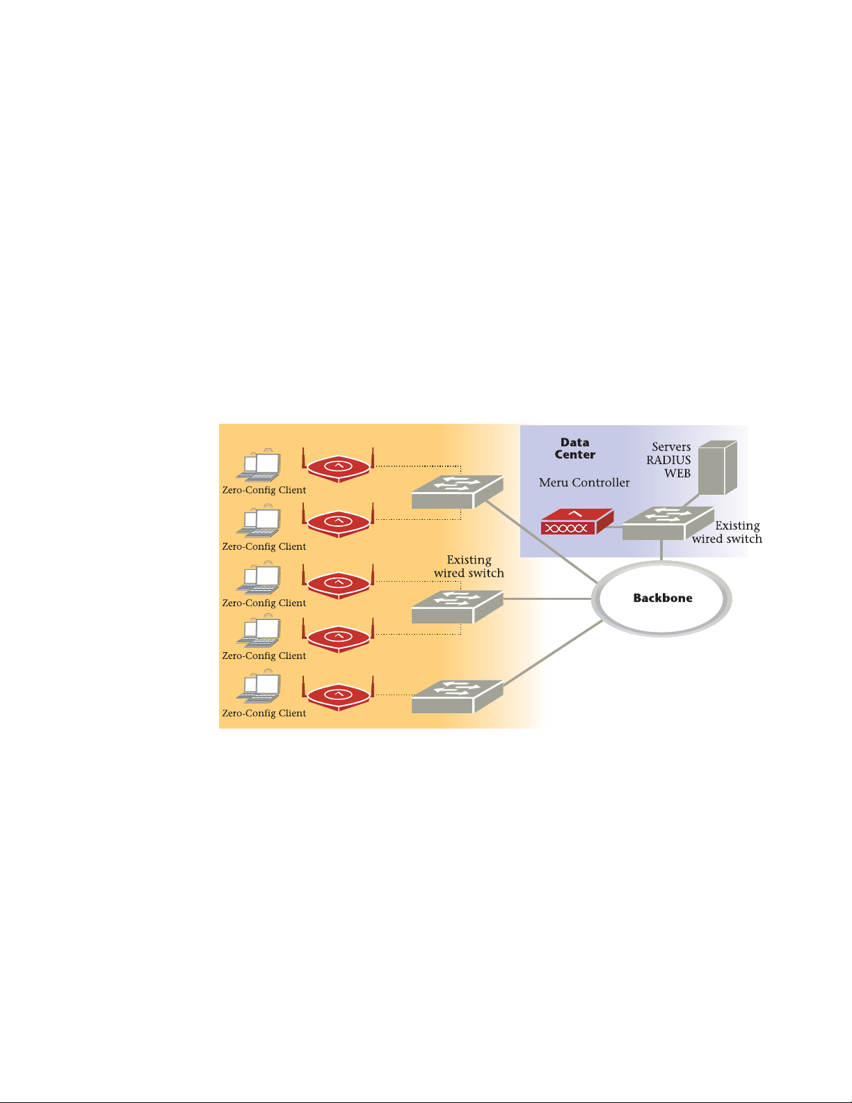
Access Points contain radio devices that communicate with the Meru Controller and
form the wireless LAN (WLAN). The Meru Controller and Access Points connect to the
site’s wired LAN through wired switches. Wireless clients associate with the Access
Points as they roam throughout the WLAN. As such, they are an extension of the wired
LAN, providing the wireless benefits of client mobility, enhanced access, and
dynamic network configuration.
Figure 1: Wireless LAN Connected to Network
© 2012 Meru Networks, Inc. Access Points 1

AP300
AP300
The AP300 Access Point series delivers high performance, full-speed, Wi-Fi certified
802.11n based on draft 2.0 connectivity while simultaneously supporting legacy
802.11a/b/g devices. AP300 is available in the configurations shown below.
AP300 Configurations
Model Configuration
AP300
AP332i
AP332e
AP320i
AP320e
AP310
AP311
AP302
AP301
Two dual-band 802.11n radios with 3x3 MIMO and internal
antennas
Two dual-band 802.11n radios with 3x3 MIMO and external
antennas
Two dual-band 802.11n radios with 3x3 MIMO and internal
antennas
Two dual-band 802.11n radios with 3x3 MIMO and external
antennas
Single dual-band 802.11n radio with 3x3 MIMO and external
antennas
Single dual-band 802.11n radio and single 802.11a/b/g
radio (AP320 upgradable) with external antennas
Two dual-band 802.11a/b/g radios (AP320 upgrade able)
with external antennas
Single dual-band 802.11a/b/g radio (AP310 upgrade able)
with external antennas
Features for the AP300 include:
802.11n support with channel bonding in both 2.4GHz and 5GHz frequency bands.
Channel bonding combines two 20Mhz channels into a single-wide 40Mhz channel
for increased throughput.
Dual-band external antenna options optimized for MIMO mode
Plug and Play deployment using centralized controller platforms
Multi-layered security including standard WPA2, 802.11i security such as
automatic traffic inspection
Each of these Access points may be powered by a standard 802.3af Po E device.
2 Meru Access Point Installation Guide © 2012 Meru Networks, Inc.
A
2
A
2
A
L
A
N
R
F
1
R
F
2
2
AP300
Air Traffic Control technology for 802.11n devices and legacy a/b/g devices
3x3 MIMO with 3 chains and 3 receive chains, delivering two spatial streams
For AP302 and AP311, the a/b/g radio software upgrades to 802.11n for maximum
investment protection.
Channel span architecture which requires no channel planning or configuration
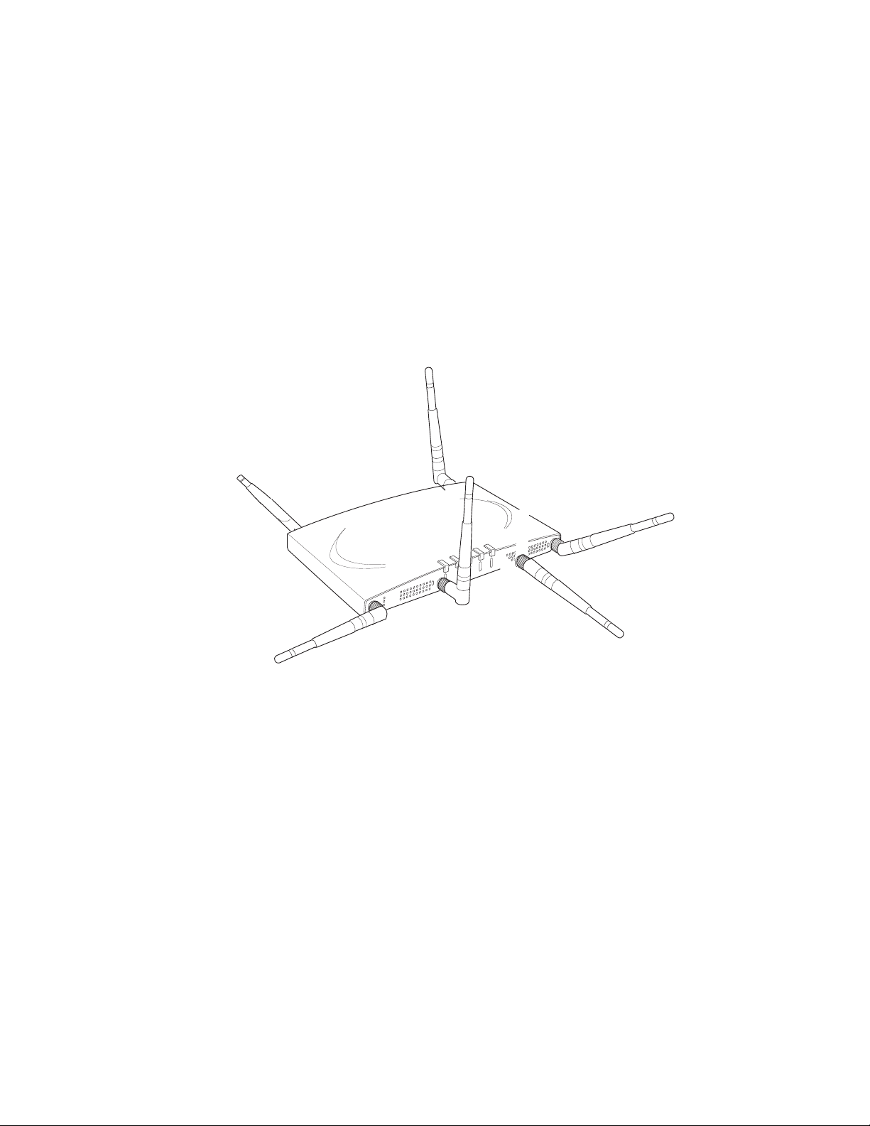
Six st andard multiban d, omni -dir ecti onal antennas for AP302, AP311, AP320, and
AP332 models. Three standard multiband, omni-directional antennas for AP310
and AP301.
Po wered by 5 volt DC input, 802.3a f or 802.3at compliant PoE device.
Figure 2: AP320e
AP320i
The AP320i Access Point is an internal-antenna AP with two dual-band 802.11n radios
and 3x3 MIMO and internal antennas.
Features for the AP320i include:
Internal antennas
802.11n support with channel bonding in both 2.4GHz and 5GHz frequency bands.
Channel bonding combines two 20Mhz channels into a single-wide 40Mhz channel
for increased throughput.
Plug and Play deployment using centralized controller platforms
Multi-layered sec urity including standard WPA2 features such as automatic traffic
inspection
Standard 802.3af Po E support and support for many 802.3at devices
© 2012 Meru Networks, Inc. Access Points 3
AP300
AP332e
Air Traffic Control technology for 802.11n devices and legacy a/b/g devices
Channel span architecture that requires no channel planning or configuration
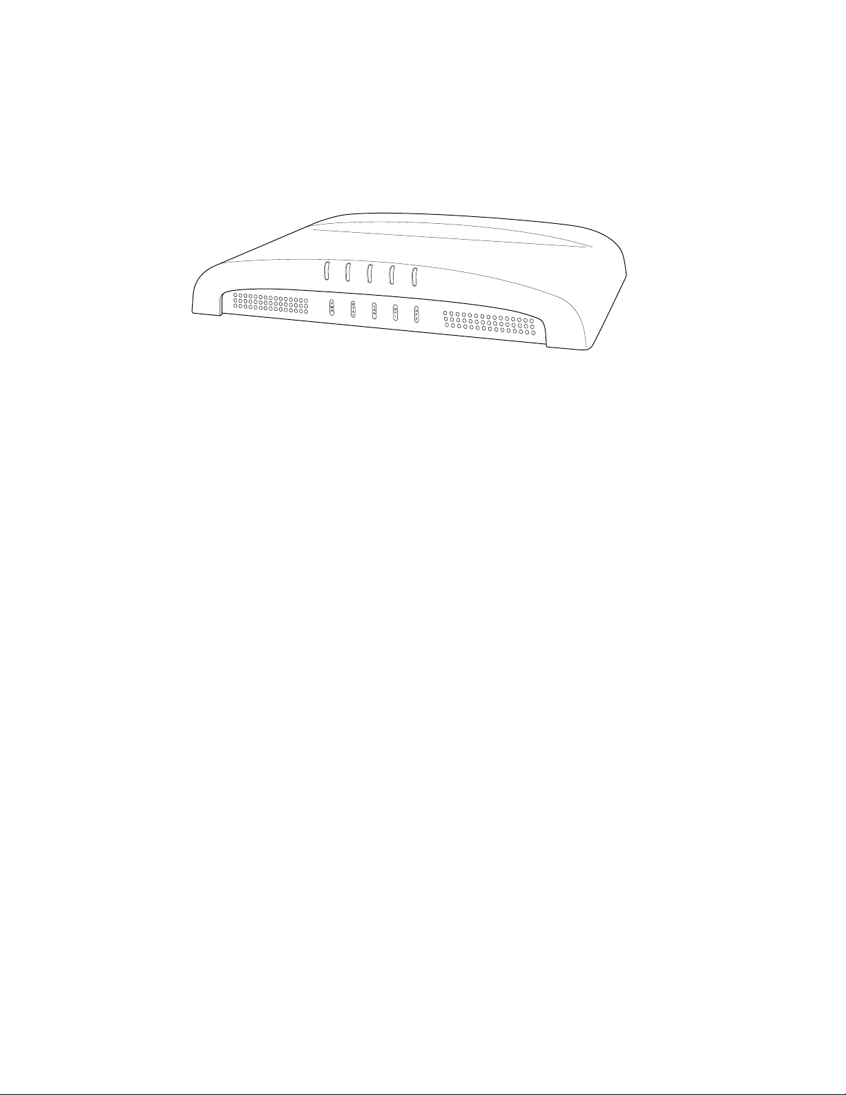
Figure 3: AP320i
The AP332e Access Point is an external-antenna AP with two dual-band 802.11n
radios and 3x3 MIMO and internal antennas.
Features for the AP332e include:
External antennas
802.11n support with channel bonding in both 2.4GHz and 5GHz frequency bands.
Channel bonding combines two 20Mhz channels into a single-wide 40Mhz channel
for increased throughput.
Plug and Play deployment using centralized controller platforms
Multi-layered sec urity including standard WPA2 features such as automatic traffic
inspection
Standard 802.3af Po E support and support for many 802.3at devices
Air Traffic Control technology for 802.11n devices and legacy a/b/g devices
Channel span architecture that requires no channel planning or configuration
Up to 128 clients per radio regardless of the encryption in use
DFS capability (in permitted regions)
Support for wired stations via the secondary ethernet interface
Pe r-packet data rates up to 450Mbps
Mesh and VPN capability with appropriate controller licenses
AP332i
The AP332i Access Point is an internal-antenna AP with two dual-band 802.11n radios
and 3x3 MIMO and internal antennas.
Features for the AP332i include:
4 Meru Access Point Installation Guide © 2012 Meru Networks, Inc.

AP300
Internal antennas
802.11n support with channel bonding in both 2.4GHz and 5GHz frequency bands.
Channel bonding combines two 20Mhz channels into a single-wide 40Mhz channel
for increased throughput.
Plug and Play deployment using centralized controller platforms
Multi-layered sec urity including standard WPA2 features such as automatic traffic
inspection
Standard 802.3af Po E support and support for many 802.3at devices
Air Traffic Control technology for 802.11n devices and legacy a/b/g devices
Channel span architecture that requires no channel planning or configuration
Up to 128 clients per radio regardless of the encryption in use
DFS capability (in permitted regions)
Support for wired stations via the secondary ethernet interface
Per-packet data rates up to 450Mbps
Mesh and VPN capability with appropriate controller licenses
© 2012 Meru Networks, Inc. Access Points 5

AP300
6 Meru Access Point Installation Guide © 2012 Meru Networks, Inc.

Safety Precautions
Chapter 2
Installing AP300
This chapter describes how to install and configure an AP300. It contains the following sections:
Safety Precautions
Unpack the AP300
Determine Power Requirements
Installation Requirements
Install the AP300
Check AP300 LED Activity
Where to Go From Here
Safety Precautions
IMPORTANT—Read and follow the regulatory instructions in Appendix B before installing and operating
this product.
If an optional power supply is used, it must be one supplied by Meru Networks.
Warning!
The AP300 is intended only for installation in Environment A as defined in IEEE 802.3af. All interconnected equipment must be contained within the same building, including the interconnected equipment's associated LAN connection.
This product is intended to be supplied by a UL Listed power supply
marked Class 2 or LPS and rated minimum 5Vdc, 3A.
© 2012 Meru Networks, Inc. Installing AP300 7

Best Practices for an AP300/AP1000 Network
Best Practices for an AP300/AP1000 Network
Read this section if you have both AP1000 and AP320i active simultaneously on the same network. The
following best practices should be followed to get optimal performance from such a mixed network.
AP320i and AP300 are interchangeable and fully compatible to share a virtual cell. It's like having
two AP300s with different antennas. The only difference is that AP320i is detected as a such in the
UI of the controller.
If pos sib l e , d o n o t d e p l o y A P 1 0 0 0 and AP3 00/AP320i a t t h e s a m e p h y sic a l l o c a t i o n ; w e r e c o m m end
that there be no overlapping coverage between AP1000 and AP300.
If AP1000 and AP300/AP320i do have overlapping coverage, you have two options. Deploy them on
seperate channels or make sure the ESS profiles on both AP types are unique. The chart below shows
two ESS scenarios, one supported, one not supported.
Supported ESS Scenario AP1000 Configuration AP320i Configuration
Two Unique ESS profiles
AP1000 and AP320i SSID
string over the air
Unsupported ESS Scenario AP1000 Configuration AP320i Configuration
Same ESS profiles
AP1000 and AP320i SSID
string over the air
Assumptions for the above best practices include:
AP1000 is using Virtual Port with BSSID Virtual Cell.
AP320i is using Virtual Po rt with BSSID Virtual Cell.
AP1000s and AP300s are on the same channel. (AP1000 and AP320i could also be on different
channels.)
AP1000s and AP320i is are on the same controller. (AP1000 and AP320i could also be on different
controllers as long as each controller has a unique controller index.)
ESS Profile name in
controller is UniqueName1
Meru Meru
ESS Profile name in
controller is same name
Meru Meru
ESS Profile name in
controller is UniqueName2
ESS Profile name in
controller is same name
8 Meru Access Point Installation Guide © 2012 Meru Networks, Inc.

Unpack the AP300
The AP300 series has five models as shown below.
Model Radios
PSM3x One a/b/g/n, one spectrum
AP320 Two a/b/g/n
AP311 One a/b/g/n, one a/b/g
AP310 One a/b/g/n
Unpack the AP300
AP302 One a/b/g
Confirm that the AP300 shipping package contains these items:
AP300 with attached mounting bracket
Six antennas (four for PSM3x)
Screws for the mounting bracket
© 2012 Meru Networks, Inc. Installing AP300 9

Determine Power Requirements
Determine Power Requirements
Power requirements vary, depending on which AP300 radios are deployed and what MIMO mode is used.
See the chart below for supported power sources for different radio configurations.
Radio 1 MIMO Radio 2 MIMO 802.3af PoE 802.3at PoE DC Power
2x2 2x2
2x2 3x3
3x3 2x2
3x3 3x3
Do not
recommend
limitation
below
802.af PoE Usage
When using System Director 3.6/4.0/4.1 and 802.3af PoE, Meru supports radios set to any MIMO settings
except 3x3 on dual radios. This is because two radios set to 3x3 MIMO using an 802.3af switch may not
have enough power if the cable is too long. Shorter cables frequently work, however. Meru supports:
Single 3x3 radio
Dual 2 x 2 radios
Dual radio with one set to 2x2 and the other one set to 3x3
When using System Director 4.0 and 802.3af, the AP300 MIMO configuration is limited to the following:
3x3 for the 5 GHz radio
2x2 for the 2.4 GHz radio
802.3at PoE Usage
When using System Director 3.6/4.0/4.1 and 802.3at, the following radio combinations are recommended:
Single 3x3 radio
Dual 2 x 2 radios
Dual radio with one set to 2x2 and the other one set to 3x3
10 Meru Access Point Installation Guide © 2012 Meru Networks, Inc.

Installation Requirements
Dual 3x3 radios are recommended with a limitation. Use 802.3at power for two 3x3 MIMO radios
when the switch has a high enough power output to support all devices on the PoE. Calculate the
amount of power needed by each AP300/AP320i in 3x3 mode (13 watts), add that to power required
by other PoE devices on the switch and compare that value to the total power output from the
switch.
The calculation for 802.3at PoE use looks something like this:
(Number of AP300s * 13watts) + (sum of all other PoE devices power requirements) <= switch
power provided
For a list of supported PoEs, see the appendix Supported Power Over Ethernet Devices for Meru APs
Installation Requirements
An array of holes on the mounting bracket allows the AP300 to be mounted on the wall and over junction boxes or molly bolts. There are holes for passing the PoE Ethernet or external power supply cable
through the bracket if the bracket is mounted on a junction box.
The AP300 has a security cable slot so you can lock the AP300 with a standard security ca ble, such as
those used to secure laptop computers.
Purchase optional mounting kits to mount the AP300 either from the ceiling or inside an enclosure:
Suspended Ceiling Rail Mounting Kit: ACC-MNT-SCRMKIT
Above Suspended Ceiling Mounting Kit (T-Bar Hanger): ACC-MNT-ASCMKIT
Inside a Hoffman Enclosure using Hoffman compatible mounting bracket: ACC-AP300-BHE (enclosure
not provided)
Above hanging ceiling tiles. Suitable for use in environmental air space in accordance with the
Section 300-22(c) of the National Electric Code and Sections 2- 128.12 - 010 (3) and 12 - 100 of the
Canadian Electrical Code. Part 1. C22. 1.
To complete AP300 installation, you need the items listed below.
Installation Type Items Required
Horizontal mounting None
Two #6 x 2" wood screws for a wood stud; or
Vertical mounting over a wall
stud
Two #6 x 1½” metal screws for a metal stud
Mounting bracket
Two #6 x 1" screws
Vertical mounting on sheetrock
© 2012 Meru Networks, Inc. Installing AP300 11
Two #4-6 x 7/8” ribbed plastic wall anchors
Mounting bracket

Install the AP300
Installation Type Items Required
Two caddy fasteners
Horizontal mounting below a
hanging ceiling
Using existing third party
brackets
Mounting above a ceiling tile
Two plastic spacers
Two keps nuts (with attached lock washer)
Mounting bracket
Use included shoulder screws
Two T-rail clips
One T-box hanger
One bracket mounting clip
Mounting bracket
Additional Equipment
A power source is needed to power the AP300. See Determine Power Requirements.
Install the AP300
Select a Location
Attach the Provided Antennas
Install the Remote Antenna Mount (optional)
Install External ACC-ANT-MIMO-MNT Antenna with Three Connectors (optional)
Install Remote ACC-ANT-6ABGN-24 Antenna with Six Connectors (optional)
Install Antennas With One Connector (optional)
Install the Access Point
Select a Location
All AP300 interconnected equipment, including the associated LAN connection, must be contained
within the same building. In addition, the AP300 location should meet the following conditions:
R elatively unobstructed access to the stations the AP serves. Se lect a location with minimal physical
obstructions between the AP and the wireless stations. In an office with cubicles, mounting the APs
below a hanging ceiling (plenum is supported) or the wall near the ceiling provides the least
obstructed communications path. On a wall, orient the AP300 horizontally so that you can read the
Meru logo without tilting your head at 90 degrees - this orientation provides optimum MIMO
performance.
12 Meru Access Point Installation Guide © 2012 Meru Networks, Inc.
ceiling
floor
Install the AP300
Access to wall outlet or a to a Power over Ethernet (P oE) connection to the network switch servicing
the controller.
We recommend planning for about 50 clients per radio (or per interference region) if you plan to
use Virtual Port and plan to have phones as clients. For a data-onl y installation, plan up to 128
clients per radio, meaning 256 for AP320 and 128 for other AP300 models. Refer to the Meru
Deployment Guides on the support site for more information.
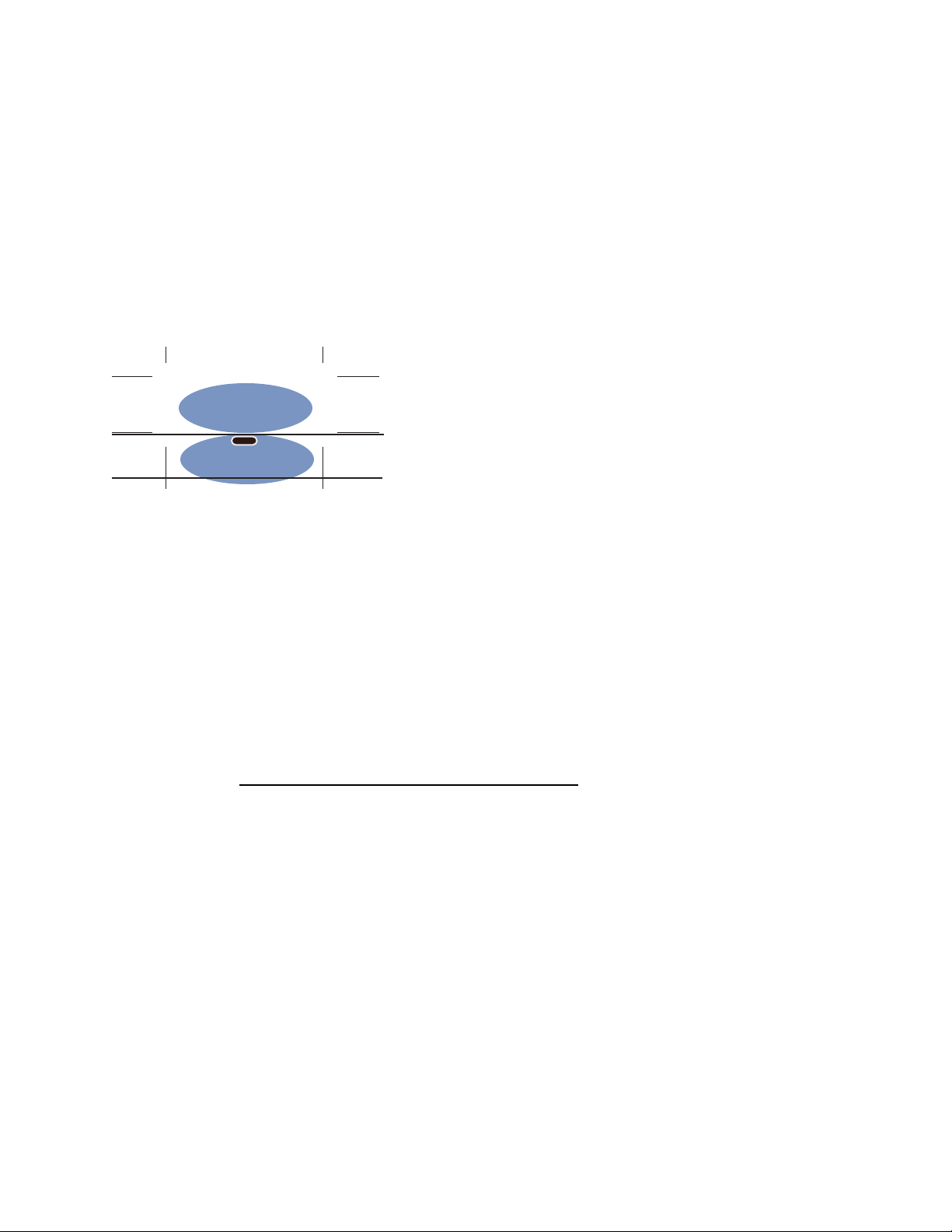
AP300 is designed to provide 360 degree omni-directional coverage as illustrated below. Plan placement with this pattern in mind.
Figure 4: Coverage Pattern for AP300 When Ceiling Mounted
Most installations receive the best coverage using the following guidelines:
Install APs toward the center of the building.
Place APs about 80 feet apart.
Do not i nstall APs near metal objects, such as heating ducts, metal door s, or electric service panels.
For best coverage, orient antennas as shown in Figure 6.
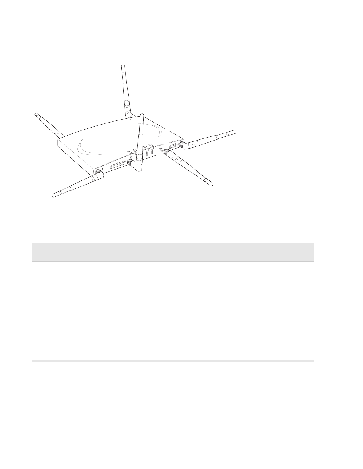
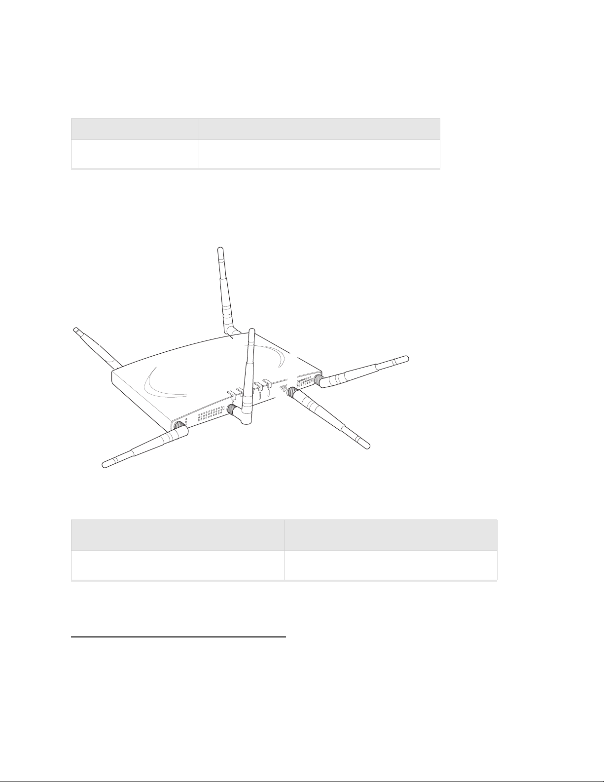
Attach the Provided Antennas
All AP300s have six external antenna ports, labeled 1 - 6. These units operate with six antennas
attached, even though some configurations don’t use all six. Instead of attaching an antenna, you can
cap unused antenna connectors with 50 ohm Reverse Polarity SMA terminators. (For a list of approved
terminators, see http://www.merunetworks.com/merusupport
only for indoor use unless they are mounted in an outdoor enclosure (see Mount AP300 in a Hoffman
Enclosure). To achieve the best performance from your AP300, position antennas at a 90 degree angle
relative to each other as shown in Figure 6. The antennas do not have to be oriented exactly as shown
in the figure, but it is important to maintain the relative angles. If for some reason you are unable to
maintain those angles, the network still operates, but you may experience up to 20% drop in throughput
depending on the antenna orientation.
.) Meru supplied antennas are suitable
© 2012 Meru Networks, Inc. Installing AP300 13
A
2
A
2
A
L
A
N
R
F
1
R
F
2
2
1 (horizontal)
6 (vertical)
2 (horizontal)
4 (horizontal)
3 (vertical)
5 (horizontal)
Install the AP300
Figure 6: AP320, AP311 or AP302 Antennas 1-6 in Ceiling and Wall Mount Configuration
The following antenna connections are used during operation of the AP320, AP311, and AP302. Note
that PSM3x APs will only have four antennas, rather than the typical six.
Table 1: AP300 With Two Radios and Corresponding Antennas
Model Radio 1 (Ant4, Ant5, Ant6) Radio 2 (Ant1, Ant2, Ant3)
PSM3x
AP320
AP311
AP302
a/b/g/n with 3 dual band omni-directional
antennas (only one radio can be N)
a/b/g/n with 3 dual band omni-directional
antennas
a/b/g/n with 3 dual band omni-directional
antennas (only one radio can be N)
a/b/g with 3 dual band omni-directional
antennas
Spectrum radio with one omni-directional
antenna.
a/b/g/n with 3 dual band omni-directional
antennas
a/b/g/n with 3 dual band omni-directional
antennas (only one radio can be N)
a/b/g with 3 dual band omni-directional
antennas
14 Meru Access Point Installation Guide © 2012 Meru Networks, Inc.
A
2
A
2
A
L
A
N
R
F
1
R
F
2
2
1 (horizontal)
2 (horizontal)
3 (vertical)
does not matter
does not matter
does not matter
Install the AP300
Table 2: AP310 With One Radios and Corresponding Antennas
Model Radio 1 (Ant1, Ant2, Ant3)
AP310 a/b/g/n with 3 dual band omni-directional antennas
The AP310 has six external antenna ports labeled 1 - 6. However, AP310 uses o nly three of those
antennas and the unused antenna connectors are blocked. Figure 7 illustrates the recommended
antenna configuration for the AP310.
Figure 7: AP310 Antennas 1-3
The following antenna connections are used during operation of the AP310.
Radio 1 Antenna Connectors for AP310 Radio2 Antenna Connectors for AP310
Ant1, Ant2, Ant3 NA
Do not leave any antenna connectors unterminated. All connectors on the AP must be terminated with
antennas or with 50 ohm Reverse Polarity SMA terminators. (For a list of approved terminators, see
http://www.m erunetworks.com/merusupport
.
The attached antennas must be the same model; if you replace one antenna, replace them all.
© 2012 Meru Networks, Inc. Installing AP300 15
Install the AP300
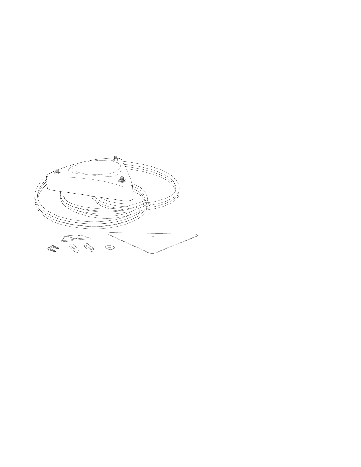
Install the Remote Antenna Mount (optional)
Use the optional Meru Remote Antenna Mount (ACC-ANT-MIMO-MN T) for one or both AP300 radios to
remotely connect the AP300 antennas. The Remote Antenna Mount allows you to relocate either your
current antennas or the optional high-gain dipole antennas to a location with clearer signal paths to
the other wireless devices in your network. The Remote Antenna Mount can be installed either below
the ceiling tile or on the wall. The default orientation for the mount is suitable for a ceiling mount,
but you can attach the mount to a wall with some modifications.
Use one mount per radio; for example AP310 needs one unit, and AP320 needs two units.The Remote
Antenna Mount uses low-loss plenum rated LMR195 cable and SMA connectors. To order this unit,
contact your Meru sales representative and refer to part number ACC-ANT-MIMO-MNT.
Figure 8: Remote Antenna Mount
00224
The remote antenna mount kit includes:
Antenna stand with attached cable. The three antenna SMA female connectors on the Antenna
Mount support AP300 antenna diversity. This featur e gives the client the ability to automatically
choose the antenna receiving the strongest signal.
Triangular ceiling mount clip for attaching to hanging ceiling (includes bolt assembly)
Three self-adhesive pads for the bottom of the unit (over the screws)
Two wall mount screws with anchors
Ceiling Mount Template
Installation diagram
Install the Remote Antenna Mount on the Ceiling
To connect the Remote Antenna Mount to the ceiling, refer to the installation diagram from the shipping box while following these steps:
1. Attach the shorter end of the screw to the center hole on the back of the Antenna Mount.
2. Remove the designated ceiling tile.
16 Meru Access Point Installation Guide © 2012 Meru Networks, Inc.

Meru
A1
A5
A6
A4 A3 A2
Meru
A1
A5
A6
A4 A3 A2
Install the AP300
3. Using the template, drill holes in the ceiling tile.
4. Replace the ceiling tile.
5. Remove a ceiling tile adjacent to the newly drilled tile for access purposes.
6. Feed the Antenna Mount cable through the larger hole in the ceiling tile until the Antenna Mount
is flush with the ceiling. The screw should now be visible above the ceiling tile (through the second
hole).
7. Place the triangular plate above the ceiling tile with the screw aligned through the plate.
8. Drop the washer onto the screw and tighten the bolt.
The Antenna Mount is now connected to the ceiling.
9. Replace the adjacent tile.
10. Connect the three Remote Antenna Mount cables to the appropriate connectors on the AP300. Be
sure to connect the three antennas that correspond to one radio. Radio 1 uses A1, A2, A3 and Radio
2 uses A4, A5, A6.
11. Attach three antennas that shipped with AP300 to the three connectors on the triangular remote
device. See Figure 8.
Install the Remote Antenna Mount on a Wall
1. Reorient the cable on the Remote Antenna Mount by removing the three screws on the back,
removing the small cover, reorienting the cable and then replacing the three screws. Discard the
small cover.
2. Connect the three R emote Antenna Mount cables to the appropriate ports on the AP300. Be sure to
connect the three antennas that correspond to one radio. Radio 1 uses A1, A2, A3 and Radio 2 uses
A4, A5, A6. PSM3x devices only utilize A1, A2, A3, and A5.
3. Attach three of the antennas that shipped with AP300 to the three ports on the triangular remote
device.
4. Orient the connected AP300 horizontally so that you can read the Meru logo without tilting your
head at 90 degrees - this orientation provides optimum MIMO performance.
© 2012 Meru Networks, Inc. Installing AP300 17

Install the AP300
Install External ACC-ANT -MIMO-MNT Antenna with Three Connectors (optional)
You can optionally use an external antenna setup with your AP300 if the controller and APs are running
System Director 3.6.1MR4 and later. Meru supports this antenna for use on one radio using 802.11n
MIMO. An AP300 with one radio, for example AP310, needs one antenna. An AP300 with two radios, for
example AP320, needs two antennas. Radio One antenna cables connect to ports A1, A2, and A3. Radio
Two cables connect to ports A4, A5, and A6. There is no preferred cabling connection; all three cables
are the same.
Calculate the antenna gain for the ACC-ANT-MIMO-MNT antenna by referring to the next three charts:
Band of Operation Gain Vertical Beamwidth Horizontal Beamwidth
2.40-2.483 GHz 2.5dB 55 degrees 360 degrees
5.15-5.85 GHz 4dB 60 degrees 360 degrees
Using This Cable Type with 2.4 GHz Calculate This Loss per Foot
RG174 0.60 dB
RG316 0.48 dB
LMR100 0.39 dB
LMR200 0.17 dB
LMR240 0.13 dB
LMR400 0.066 dB
LMR600 0.043 dB
Using This Cable Type with 5 GHz Calculate This Loss per Foot
RG174 1.02
RG316 0.76
LMR100 0.59 dB
18 Meru Access Point Installation Guide © 2012 Meru Networks, Inc.

Using This Cable Type with 5 GHz Calculate This Loss per Foot
LMR200 0.24 dB
LMR240 0.19 dB
LMR400 0.100 dB
LMR600 0.066 dB
Install the AP300
© 2012 Meru Networks, Inc. Installing AP300 19

Install the AP300
Install Remote ACC-ANT-6ABGN-24 Antenna with Six Connectors (optional)
You can optionally use an external antenna setup with your AP300 if the controller and APs are running
System Director 3.6.1MR4 and later. Meru supports this antenna for use on AP300s with two radios, for
example AP320. This antenna has six connectors to connect to both radios to a dual-radio AP30 0 and
it supports 802.11n MIMO operation.
The six cables on the ACC-ANT-6ABGN-24 antenna are already tagged with the numbers 1 - 6. Connect
the antenna cables to the AP antenna ports as shown here:
Meru AP300 Antenna
Connector
A1 6
A2 5
A3 4
Antenna Cable Numbered
A4 3
A5 2
A6 1
A5
AP300
A3A4
A6
A2 A1
2
1
4
5
3
antenna
6
Calculate the antenna gain for the ACC-ANT-6ABGN-24 antenna by referring to the next three charts:
Band of Operation Gain Vertical Beamwidth Horizontal Beamwidth
2.40-2.483 GHz 2.5dB 55 degrees 360 degrees
5.15-5.85 GHz 4dB 60 degrees 360 degrees
20 Meru Access Point Installation Guide © 2012 Meru Networks, Inc.

Using This Cable Type with 2.4 GHz Calculate This Loss per Foot
RG174 0.60 dB
RG316 0.48 dB
LMR100 0.39 dB
LMR200 0.17 dB
LMR240 0.13 dB
LMR400 0.066 dB
LMR600 0.043 dB
Install the AP300
Using This Cable Type with 5 GHz Calculate This Loss per Foot
RG174 1.02
RG316 0.76
LMR100 0.59 dB
LMR200 0.24 dB
LMR240 0.19 dB
LMR400 0.100 dB
LMR600 0.066 dB
Install Antennas With One Connector (optional)
You can optionally use an external antenna setup with your AP300 if the controller and APs are running
System Director 3.6.1MR4 or 4.0.
When deploying an AP300 with only one antenna per radio, AP300 cannot support 802.11 n MIMO operation. Also, any antenna ports that are not used to connect to an antenna must be terminated with 50
ohm Reverse Polarity SMA terminators. (For a list of approved terminators, see http://www.merunetworks.com/merusupport.) Connect the antenna using one cable per radio as described in the table
below. These instructions can be used to replace an AP200 existing antenna configuration with an
AP300. For these instructions, each port on the AP300 is identified by a label A1 to A6.
© 2012 Meru Networks, Inc. Installing AP300 21

Meru
A1
A5
A6
A4 A3 A2
(BG or A radio antenna)
Meru
A1
A5
A6
A4 A3 A2
(BG radio antenna)
(A radio antenna)
Meru
A1
A5
A6
A4 A3 A2
(BG or A radio antenna)
(BG or A radio antenna)
Meru
A1
A5
A6
A4 A3 A2
(BG radio antenna)
(A radio antenna)
(A radio antenna)
(BG radio antenna)
Install the AP300
AP Has One BG or A Radio, One Antenna
AP Has Two Radios (BG and A), One Antenna For Each
AP Has One Radio, Two Antennas
AP Has Two Radios, Four Antennas
22 Meru Access Point Installation Guide © 2012 Meru Networks, Inc.

Install the AP300
Install the Access Point
AP300 ships with a detachable mounting bracket. The AP300 is designed to be compatible with brackets
supplied by Meru and by other vendors as follows. The AP300 mounts directly on the AP150 mounting
bracket. If you are replacing AP200s/AP300s, the AP300 bracket can be mounted on the old
AP200s/AP300s bracket with included shoulder screws; you don’t need to remove the old brackets.
AP300 can also be directly mounted on third-party brackets such as Proxim AP4000 and Cisco standard
brackets.
You can mount an AP300 in the following ways:
Mount AP300 Horizontally on a Shelf
Mount AP300 Vertically on a Wall
Mount AP300 Below a Suspended Ceiling
Mount AP300 Above a Suspended Ceiling (Plenum)
Mount AP300 in a Hoffman Enclosure
Mount AP300 Horizontally on a Shelf
When mounting an AP300 horizontally, remove the mounting bracket. Be sure to position the antennas
vertically when an AP300 sits on a surface.
Mount AP300 Vertically on a Wall
Note:
same bracket. If you are replacing AP300s, the AP300 bracket can be attached to the old bracket with
included shoulder screws; you don’t have to remove the old brackets. This bracket will also mount
seamlessly into the Proxim AP4000 bracket and standard Cisco brackets.
To mount an AP300 on a wal l:
1. Using the bracket holes as a guide, mark the location on the wall for the two AP bracket mounting
2. Drill holes at the locations you marked:
3. If you are using plastic anchors, install them in the holes.
4. Screw in the screws most of the way.
5. Mount the bracket on the screws, placing the ci rcular portion of the keyhole mounts over the screw
If you are replacing AP150s, you can use the existing brackets: the AP150 and AP300 use the
screws. If possible, center the mounting screws on a wall stud. If you do not center the mounting
screws on a wall stud, use plastic wall anchors. Orient the AP300 horizontally so that you can read
the Meru logo without tilting your head at 90 degrees - this orientation provides optimum MIMO
performance.
— 3/16-inch holes if you are using plastic anchors
— 1/8-inch holes if you are using only the screws
heads and sliding the bracket down.
6. Connect one end of the Ethernet cable to the switch and the other end to the AP300 Ethernet port.
© 2012 Meru Networks, Inc. Installing AP300 23

Install the AP300
Suspended ceiling T-rail
Caddy fastener
Spacer
Mounting bracket
Washer
00257
Caution!
mistakenly be plugged into the Console port. If you do this, the AP won’t power up.
7. If you are not using a PoE device, connect an external power supply to the power connector and
plug it into the wall.
Be sure to connect the Ethernet cable to the Ethernet port; the cable can
Mount AP300 Below a Suspended Ceiling
The optional suspended ceiling mounting kit (ACC-MNT-SCRMKIT) allows the AP300 mounting bracket
to attach to suspended ceiling T-rails (see Figure 9).
Note:
to the mounting bracket.
Figure 9: Mounting any AP to a Suspended Ceiling Rail using ACC-MNT-SCRMKIT
T o comply with NEC code, attach a groun ding wire to any of the screws used to attach the AP300
To mount an AP300 below a suspended ceiling:
1. Determine the location on the ceiling rail where the AP will be mounted and remove the ceiling
tiles.
2. Place each of the two caddy fasteners on the ceiling T-rail and twist to attach to the rail.
3. Adjust the distance between the caddy fasteners by using the mounting bracket holes as a guide.
4. Tighten the caddy fasteners in place using a standard screwdriver. Do not overtighten.
5. Place each spacer on the caddy fastener stud. The spacer legs should contact the ceiling T-rail.
6. Align the mounting bracket keyholes with the caddy fastener studs and slide the AP300 to the
narrow end of the hole.
7. Attach a keps nut to each caddy fastener stud and hand tighten. Do not overtighten.
24 Meru Access Point Installation Guide © 2012 Meru Networks, Inc.

Install the AP300
8. Align the AP300 mounting posts over the circular portion of the keyhole mounts, push the AP in and
slide the AP down until it engages with the locking detents (see Figure 9). You should hear it snap
in place.
9. For each antenna, loosen the knurled ring at the base of the antenna, orient the antenna and then
retighten the ring.
10. Connect one end of the PoE 100BaseT Ethernet cable to the 100/1000 Ethernet connector.
Caution!
mistakenly be plugged into the Console port. If you do this. the AP won’t power up.
Be sure to connect the Ethernet cable to the Ethernet port; the cable can
© 2012 Meru Networks, Inc. Installing AP300 25

Install the AP300
Mount AP300 Above a Suspended Ceiling (Plenum)
Use the optional T-bar box hanger mounting kit to mount AP300 above suspended ceiling T-rails (see
Figure 11). The installation attaches the T-bar box hanger to the ceiling rails and then the AP300
attaches to the T-bar box hanger. Note that AP300 mounted above the ceiling has about 2-3 dBm less
RF coverage than AP300 mounted under the ceiling.
The AP300 with the metal enclosure exposed meets the requirements for fire resistance and low
smoke-generating characteristics required by Section 300-22(C) of the National Electrical Code (NEC)
for installation in a building’s environmental air space.
You may need to modify thicker tiles to support this installation.
Warning!
power the AP300 only with a PoE, not a power supply. See Power Supplies for part
numbers.
Warning!
suitable under NEC Article 800.50 and marked accordingly for use in plenums and airhandling spaces with regard to smoke propagation, such as CL2-P, CL3-P, MPP (Multi
Purpose Plenum), or CMP (Communications Plenum). Use Ethernet cable that meets
the requirements for operating in plenums and environmental air space in
accordance with Section 300-22(C) of the NEC.
To mount an AP300 above the ceiling with the optional T-bar kit, follow these steps:
1. Determine the location on the ceiling rails where the AP will be mounted and remove the ceiling
tile.
2. Unpack the T-bar hanger kit.
3. Remove the mounting bracket plate from the underside of the AP300.
4. Locate the mounting bar (depicted in Figure 10) and the two screws provided for it.
Figure 10: Mounting Bar
When installed in air-handling spaces, such as above a suspended ceiling,
Any Fast Ethernet (FE) cables installed in air-handling spaces should be
26 Meru Access Point Installation Guide © 2012 Meru Networks, Inc.

Install the AP300
5. Place the mounting bar on top of the crossbar of the mounting bracket, and place the AP300 bracket
(which you removed earlier) against the underside of the crossbar. The crossbar should be
sandwiched between the mounting bar and the mounting bracket.
6. Insert the screws removed from the mounting bar through the underside of the mounting bracket
(therefore screwing upwards through the mounting bar) to attach the bracket to the crossbar. See
Figure 11.
Figure 11: Correct Screw Location
00263
Note:
7. Reattach the AP300 to its mounting bracket using the thumbscrews provided.
8. For each antenna, loosen the knurled ring at the base of the antenna, point the antenna down, then
retighten the ring (or attach the antennas, if not already done).
9. Attach the legs of the T-Bar kit to the bars on which the AP is to be mounted by sliding the clips
into place on top of the T-Bars.
10. Remove one nut from each leg.
11. Slide the crossbar into place on top of the legs and replace the nuts on top.
12. Connect a drop wire to a building structural element and through the oval hole provided in the
bracket mounting clip (on the underside of the AP300). The U.S. National Electrical Safety Co de
requires this additional support.
13. Connect one end of the PoE Ethernet cable to the Ethernet connector.
The AP300 shown in Figure 11 does not have the external antennas attached
in order to aid in installation. These can be connected after mounting.
© 2012 Meru Networks, Inc. Installing AP300 27

Install the AP300
Caution!
mistakenly be plugged into the Console port. If you do this. the AP won’t power up.
Note:
14. Check that the AP300 is operating correctly before replacing the ceiling tile to the ceiling. Verify
correct operation using the LEDs, as shown in Check AP300 LED Activity.
Be sure to connect the Ethernet cable to the Ethernet port; the cable can
Use a shielded Cat 5e (or greater) Ethernet cable in order to comply with
international electromagnetic emissions limits.
Mount AP300 in a Hoffman Enclosure
Meru has designed a custom mounting bracket compatible with a Hoffman enclosure (www.hoffmanonline.com). This bracket is available exclusively through Meru and orde rable as part number ACC-AP300-
BHE. To mount an AP300 in a Hoffman enclosure, follow these steps:
1. Place AP300 upside down on a soft flat surface.
2. Remove and discard the wall/ceiling mounting bracket.
3. Attach either the provided antennas or an external antenna.
4. Remove and discard the four rubber feet.
5. Position the Hoffman bracket (ACC-AP300-BHE) onto the back of the AP300 with the four Hoffman
mounting screws facing downwards.
Figure 12: Hoffman Bracket ACC-AP300-BHE
00230
6. Using a Phillips screw driver, attach the bracket using the two supplied 6-32 3/16 SEMS screws.
7. Flip the assembly over and mount into the Hoffman enclosure, attach the Ethernet cable to the
AP300 rotating the assembly to place the Ethernet cable within the enclosure.
8. Using a Phillips screw driver, tighten the four bracket screws to the enclosure.
9. Adjust the antennas as needed.
28 Meru Access Point Installation Guide © 2012 Meru Networks, Inc.

A
3
A
2
L
A
N
S
T
T
A
P
W
R
R
F
1
R
F
2
00217
P
W
R
S
T
A
T
L
A
N
R
F
1
R
F
2
Check AP300 LED Activity
Check AP300 LED Activity
When AP300 first connects to the controller (and any time the access point is rebooted), the AP initializes and is then programmed by the controller. When the AP first powers up, all LEDs are green.
Figure 13: AP300 Status LEDs
After the AP300 is connected, check the status of the LEDs. The functions of the five LEDs are described
below.
© 2012 Meru Networks, Inc. Installing AP300 29

Check AP300 LED Activity
AP300/AP320i LED Descriptions
LED Function Troubleshooting
Power
Status
LAN
off—no power
green—presence of power
off—no power
green—booting stage 1
blinking green and off—booting stage 2
blinking green and white—discovering the
controller
blinking green and blue—downloading a
configuration from the controller
blinking blue and off—AP is online and
enabled, working state
blinking red and yellow—failure; consult
controller for alarm state
off—no power or no link
green—link status OK (at any speed)
green/blinking—activity (at any speed)
red—auto negotiation failure
If the status LED is blinking red and
yellow, there is an alarm on the AP.
Determine what the alarm is by
clicking Monitor > Dashboard >
Alarms and looking at the AP alarms.
You can also use the CLI commands
show alarm and show log.
If the LAN LED is red, auto
negotiation failed. This means that
you have a problem with cabling or
with the AP’s switch.
If one of the radio LEDs is yellow, it is
either disabled or in scanning mode.
To see if the AP is disabled, click
Configuration > Wireless > Radio >
select a radio and then look at
Administrative Status, which should
off—no radio present
Radio 1
Radio 2
30 Meru Access Point Installation Guide © 2012 Meru Networks, Inc.
green—radio enabled
green blinking—data activity
yellow—disabled or in scanning mode
red—failure
be set to Up. To see if the AP is in
Scanning Mode, click Configuration >
Wireless > Radio > select a radio and
look at AP Modes, which should be set
to Normal Mode.
If one of the radio LEDs is red, the
radio failed. Check the alarms
(Monitor > Dashboard > Alarms),
diagnostics (Monitor > Diagnostics >
Radio), and statistics (Monitor >
Dashboard > Radio) on the AP’s
controller to determine the cause.

Where to Go From Here
Change LED Appearance
If you want to change the appearance of the LEDS, follow these steps:
1. From the controller, click Configuration > Devices > AP, and then select the AP.
2. Select one of these settings for the LED Mode setting:
— Normal: LEDs are as described below
— Node ID: Not supported in release 4.1
— Blink: Sets all LEDs flashing; this is useful to locate an AP
— Dark: Turns off all LEDs
3. Click OK.
Where to Go From Here
Now that the AP1000 is installed, refer to the Meru System Director Getting Started Guide for instructions on initializing the hardware. Return to this chapter to check the status of the LEDs once the WLAN
is operational.
© 2012 Meru Networks, Inc. Installing AP300 31

Where to Go From Here
32 Meru Access Point Installation Guide © 2012 Meru Networks, Inc.

Safety Precautions
Chapter 3
Installing AP320i
AP320i is supported by System Director versions 3.6.1 and greater, but full support begins with System
Director release 4.x and later. Because of this, when using AP320i with System Director 3.6.1, the unit
shows as an AP300, for example AP320 instead of AP320i. All AP320i units still function correctly, they
just display as AP300 because AP320i did not exist when System Director 3.6.1 was released.
This chapter describes how to install and configure an AP320i. It contains the following sections:
Safety Precautions
Best Practices for an AP320i/AP1000 Network
Unpack the AP320i
Determine Power Requirements
Installing AP320i
Check AP320i LED Activity
Where to Go From Here
Safety Precautions
IMPORTANT—Read and follow the regulatory instructions in Appendix B before installing and operating
this product.
If an optional power supply is used, it must be one supplied by Meru Networks.
Warning!
The AP320i is only intended for installatio n in Environment A as defined in IEEE 802.3af. All interconnected equipment must be contained within the same building, including the interconnected equipment's associated LAN connection.
This product is intended to be supplied by a UL Listed power supply
marked Class 2 or LPS and rated minimum 5Vdc, 3A.
© 2012 Meru Networks, Inc. Installing AP320i 33

Best Practices for an AP320i/AP1000 Network
Best Practices for an AP320i/AP1000 Network
Read this section if you have both AP1000 and AP320i active simultaneously on the same network. The
following best practices should be followed to get optimal performance from such a mixed network.
AP320i and AP300 are interchangeable and fully compatible to share a virtual cell. It's like having
two AP300s with different antennas. The only difference is that AP320i is detected as a such in the
UI of the controller.
If possible, do not deploy AP1000 and AP320i at the same physical location; we recommend that
there be no overlapping coverage between AP1000 and AP300.
If AP 1000 and A P 3 20 i do have overlappi ng coverage, you have two options. De ploy them on seperate
channels or make sure the ESS profiles on both AP types are unique. The chart below shows two ESS
scenarios, one supported, one not supported.
Supported ESS Scenario AP1000 Configuration AP320i Configuration
Two Unique ESS profiles
AP1000 and AP320i SSID
string over the air
Unsupported ESS Scenario AP1000 Configuration AP320i Configuration
Same ESS profiles
AP1000 and AP320i SSID
string over the air
Assumptions for the above best practices include:
AP1000 is using Virtual Port with BSSID Virtual Cell.
AP320i is using Virtual Po rt with BSSID Virtual Cell.
AP1000s and AP320is are on the same channel. (AP1000 and AP320i could also be on different
channels.)
AP1000s and AP320i is are on the same controller. (AP1000 and AP320i could also be on different
controllers as long as each controller has a unique controller index.)
ESS Profile name in
controller is UniqueName1
Meru Meru
ESS Profile name in
controller is same name
Meru Meru
ESS Profile name in
controller is UniqueName2
ESS Profile name in
controller is same name
34 Meru Access Point Installation Guide © 2012 Meru Networks, Inc.

Unpack the AP320i
Unpack the AP320i
Confirm that the shipping box contains the following:
AP320i with an attached ceiling mounting bracket
Wall mount bracket with screws
Small locking key for ceiling or wall mount locking
Determine Power Requirements
Power requirements vary, depending on what MIMO mode is used. See the chart below for supported
power sources for different radio configurations.
Radio 1 MIMO Radio 2 MIMO 802.3af PoE 802.3at PoE DC Power
2x2 2x2
2x2 3x3
3x3 2x2
3x3 3x3
Do not
recommend
802.af PoE Usage
When using System Director 3.6/4.0/4.1 and 802.3af PoE, Meru supports radios set to any MIMO settings
except 3x3 on dual radios. This is because two radios set to 3x3 MIMO using an 802.3af switch may not
have enough power if the cable is too long. Shorter cables frequently work, however. Meru supports:
Single 3x3 radio
Dual 2x2 radios
Dual radio with one set to 2x2 and the other one set to 3x3
When using System Director 4.0/4.1 and 802.3af, AP320i MIMO configuration is limited to the following:
3x3 for one radio
2x2 for the other radio
© 2012 Meru Networks, Inc. Installing AP320i 35

Additional Equipment
802.3at Usage
When using System Director and 802.3at, the following radio combinations are recommended:
Single or dual 3x3 radio
Dual 2 x 2 radios
Dual radio with one set to 2x2 and the other one set to 3x3
For a list of supported PoEs, see the appendix Supported Power Over Ethernet Devices for Meru APs
Additional Equipment
A power source is needed to power the AP320i. See Determine Power Requirements for options. If you
want to lock an AP320i to the ceiling or wall, you need a small key like the ones used to lock suitcases.
.
Installation Type Order These Additional Items
Horizontal mounting None
Vertical mounting over a wall
stud
Vertical mounting on sheetrock None
Horizontal mounting below a
hanging ceiling
Reusing an existing bracket from
another AP
None
None
For connection to Meru AP150 only, order shoulder screws, Meru
part number 665-00012 (SCR, PIC.1/4*1/8 10-32 SKT SHLDR SCR 303
STNLS). Connection to other brackets does not require this.
36 Meru Access Point Installation Guide © 2012 Meru Networks, Inc.

Installing AP320i
Installing AP320i
Select a Location
All AP320i interconnected equipment must be contained within the same building, including the interconnected equipment's associated LAN connection. Ceiling mounting is recommended but wall
mounting is also supported. In addition, the AP320i should be mounted in a location that meets the
following conditions:
R elatively unobstructed access to the stations the AP serves. Se lect a location with minimal physical
obstructions between the AP and the wireless stations. In an office with cubicles, mounting the APs
below a hanging ceiling (plenum is supported) or the wall near the ceiling provides the least
obstructed communications path. On a wall, orient the AP320i horizontally so that you can read the
Meru logo without tilting your head at 90 degrees - this orientation provides optimum MIMO
performance.
We recommend planning for about 50 clients per radio (or per interference region) if you plan to
use Virtual Port and plan to have phones as clients. For a data-onl y installation, plan up to 128
clients per radio, meaning 256 for AP320i. Refer to the Meru Deployment Guides on the support site
for more information.
Access to wall outlet or a to a Power over Ethernet (P oE) connection to the network switch servicing
the controller.
AP320i is designed to provide 180 degree omni-directional coverage as illustrated below. Plan placement with this pattern in mind.
Figure 14: Coverage Pattern for AP320i When Ceiling Mounted
ceiling
floor
Most installations receive the best coverage using the following guidelines:
Install APs toward the center of the building.
Place APs about 80 feet apart.
Do not i nstall APs near metal objects, such as heating ducts, metal door s, or electric service panels.
If you install AP320i on a pole , keep in m ind th at co verag e will be 18 0 deg rees . Do n ot mo unt tw o
AP320is back to back on a pole to achieve 360 degree coverage, however, because the two units
could interfere with each other.
© 2012 Meru Networks, Inc. Installing AP320i 37

Installing AP320i
T-bar
(in ceiling)
Mounting bracket Press this tab down
with T-bar.
AP300i
00235
Install the Access Point
The AP320i ships with a detachable ceiling m ounting bracket, making the unit ready for ceiling
mounting. You can also use the included wall-mount bracket by attaching it to the default ceilingmount one that comes already attached. Installation directions are provided below.
Mount AP320i in any of the following ways:
Mount AP320i Below a Suspended Ceiling
Mount AP320i Above a Suspended Ceiling
Mount AP320i Vertically on a Wall
Set AP320i on a Shelf
Mount AP320i Below a Suspended Ceiling
AP320i ships ready to mount on a suspended ceiling; the attached bracket clips to a ceiling rail.
To mount an AP320i below a suspended ceiling, follow these steps:
1. Determine the location on the ceiling rail where the AP will be mounted and remove the ceiling
tiles.
2. Align the mounting bracket with the slots indicated in Figure 15 below.
Figure 15: Install AP320i Below a Suspended Ceiling
3. P ress down on the tab indicated in Figure 15 and rotate the AP320i into place. Note that depending
on the date on which the AP was shipped, there may be two tabs on the underside (as shown above).
38 Meru Access Point Installation Guide © 2012 Meru Networks, Inc.

Installing AP320i
g00240
LAN 5V DCCON
console Ethernet
T-bar
(in ceiling)
Mounting bracket
AP300i
Security
clip
Lock security clip.Security clip fully inserted.
Insert security clip.
00236
4. Connect one end of the CAT5 (or greater) Ethernet cable to the 100/1000 Ethernet connector.
Caution!
Be sure to connect the Ethernet cable to the Ethernet port. The cable can
mistakenly be plugged into the Console port; if you do this, the AP won’t power up.
Figure 16: AP320i Ethernet Port on the Right
5. Optionally install a small lock (not supplied) to secure the AP320i to the ceiling rail. See Figure 17.
To do this, you need the security key that shipped with the AP320i.
Figure 17: Optionally Install Your Own Lock on AP320i
Mount AP320i Above a Suspended Ceiling
Note:
© 2012 Meru Networks, Inc. Installing AP320i 39
AP320i is not plenum-rated and should only be mounted above ceilings in
non-plenum air space, such as a return airflow for air conditioning.

Installing AP320i
Use the optional T-bar box hanger mounting kit to mount AP320i above suspended ceiling T-rails. The
installation attaches the T-bar box hanger to the ceiling rails and then the AP320i attaches to the Tbar box hanger. Note that AP320i mounted above the ceiling has about 2-3 dBm less RF coverage than
AP320i mounted under the ceiling.
You may need to modify thicker tiles to support this installation.
Warning!
When installed in air-handling spaces, such as above a suspended ceiling,
power the AP320i only with a PoE, not a power supply. See Power Supplies for part
numbers.
To mount an AP 320i above the c eiling with th e optional T-bar kit, follow these steps:
1. Determine the location on the ceiling rails where the AP will be mounted and remove the ceiling
tile.
2. Unpack the T-bar hanger kit.
3. Attach the mounting bar (depicted in Figure 18) to the mounting brace (which looks like a small
handle) with the crossbar of the mounting kit sandwiched between them. See Figure 19.
Figure 18: Mounting Bar
40 Meru Access Point Installation Guide © 2012 Meru Networks, Inc.

Figure 19: Assembled Mounting Bracket
00624
Installing AP320i
4. Gently press the bracket attached to the AP320i against the mounting brace and rotate it into place
until the locking mechanism clicks. Note that this is essentially the same process as depicted in
Figure 21.
5. Remove a nut from each leg of the T-Bar kit and slide the crossbar on top of them.
6. Replace the nuts removed to lock the crossbar into place on the legs.
7. Attach the clips on either side of the T-Bar kit to the ceiling tile rails on which the full setup is to
be mounted.
8. Connect a drop wire to a building structural element and through the hole provided in the bracket
mounting clip (on the underside of the AP320). The U.S. National Electrical Safety Code requires
this additional support.
9. Connect one end of the PoE Ethernet cable to the Ethernet connector.
Caution!
Be sure to connect the Ethernet cable to the Ethernet port; the cable can
mistakenly be plugged into the Console port. If you do this. the AP won’t power up.
Note:
Use a shielded Cat 5e (or greater) Ethernet cable in order to comply with
international electromagnetic emissions limits.
Check that the AP320i is operating correctly before replacing the ceiling tile to the ceiling. Verify
correct operation using the LEDs, as shown in Check AP320i LED Activity.
© 2012 Meru Networks, Inc. Installing AP320i 41

Installing AP320i
ACC-MNT-SCRMKIT-02
ACC-MNT-SCRMKIT-03
Mount AP320i Below a Recessed Ceiling
The optional recessed ceiling mounting kit allows the AP320i mounting bracket (which is attached to
the AP when it is shipped) to be attached to a recessed ceiling rail by extending the distance from the
rail to the AP. This kit can be adjusted to fit either a wide or thin rail size.
The recessed ceiling mounting kit is part number ACC-MNT -SCRMKIT -02 prior
to AP revision N. As of revision N, however, the AP ships with a slightly
Note:
Figure 20: ACC-MNT-SCRMKIT-02 and -03
different mounting bracket and utilizes ACC-MNT-SCR MKIT-03 for rece ssed
mounting. Be sure to order the correct part number as associated with your
AP revision. Refer to Figure 20 for examples.
To mount AP320i below a recessed ceiling, follow these steps:
1. Determine the width of the ceiling rail to be used. This will tell you whether you need to adjust
the extender bracket. If the ceiling rail is wider (23.8mm), you do not have to adjust anything;
continue to step 3.
2. For a narrow ceiling rail (22.2mm), adjust the bracket. Remove the two screws shown in Figure 20
and flip one side over. This will result in a narrower channel. Tighten the screws.
3. Attach the bracket to the AP by rotating it into place as shown in Figure 21.
42 Meru Access Point Installation Guide © 2012 Meru Networks, Inc.

Figure 21: Rotate AP320i into Place on the Recessed Ceiling Rail
00253
T-bar
(in ceiling)
Mounting bracket
Adjustable bracket
AP300i
00256
Installing AP320i
Note:
Figure 21 depicts ACC-MNT-SCRMKIT-02 being used. This same procedure is
used for ACC-MNT-SCRMKIT-03 as well.
4. Attach the bracket shown in Figure 22 to the ceiling rail. Loosen the two screws enough to slip the
ceiling rail into the channel and then tighten the screws.
Figure 22: Tighten the Brackets to Fit the T-Bar
Mount AP320i on an Interlude/Silhouette T-Bar
The optional mounting kit for ceilings with Interlude / Silhouette T-bar (ACC-MNT-SCRMKIT-04) allows
the AP320i (as of Revision N) to attach to this type of ceiling by extending the distance from the ceiling
rail to the AP. See Figure 23.
© 2012 Meru Networks, Inc. Installing AP320i 43

Installing AP320i
Figure 23: Interlude Tile Bracket
Note:
The mounting procedure for the interlude bracket is identical to that described in Mount AP320i Below
a Recessed Ceiling. Essentially, fit the bracket to the ceiling T-bar and twist the AP into place on it.
Refer to the previous section for step-by-step instructions.
The interlude mounting bracket can only be used for APs post-revision N.
Mount AP320i Vertically on a Wall
Note that your AP320i may utilize one of two different wall mount brackets (depending on the product
revision). Prior to revision N, the bracket twisted into position with the AP (shown in Figure 24). The
updated bracket (post revision N) slides into place with three mounting screws. For the former bracket,
follow the instructions below. For the updated version, refer to Using the Updated AP320i Wall Mount
Bracket.
The AP320i ships with a ceiling mount br acket already connected to the unit and an additional separate
wall bracket. When wall mounting a unit, you will attach the wall mount bracket to the wall, then
attach the ceiling bracket (including AP320i) to the wall bracket. If you are replacing an A P200, the
AP320i wall bracket can be mounted on top of the old bracket us ing shoulder screws (not included);
you don’t need to remove the old bracket. If you are replacing an AP150 or AP300, the AP320i can also
be mounted on top of the old bracket after removing the ceiling mount bracket that ships attached by
default (no additional screws required).
To mount an AP320i o n sheetrock or wall studs, follow these steps:
1. Using the wall bracket holes as a guide, mark the location on the wall for two AP bracket mounting
screws. Orient the connected AP320i horizontally so that you can read the Meru logo without tilting
your head at 90 degrees - this orientation provides optimum MIMO performance.
44 Meru Access Point Installation Guide © 2012 Meru Networks, Inc.

Figure 24: AP320i Wall Bracket
00234
g00240
LAN 5V DCCON
console Ethernet
If possible, center the mounting screws on a wall stud. If you do not cente r the mounting screws on a wall stud, use plastic wall anchors.
2. Drill holes at the locations you marked:
— 3/16-inch holes if you are using plastic anchors
— 1/8-inch holes if you are using only the screws
3. If you are using plastic anchors, install them in the holes.
4. Screw in the screws most of the way.
Installing AP320i
5. Mount the bracket on the screws, placing the ci rcular portion of the keyhole mounts over the screw
heads and sliding the bracket down. Tighten the screws to lock the bracket in place.
6. Connect one end of the Ethernet cable to the switch and the other end to the AP320i Ether net port.
Caution!
Be sure to connect the Ethernet cable to the Ethernet port. The cable can
mistakenly be plugged into the Console port; if you do this. the AP won’t power up.
Figure 25: AP320i Ethernet Port on the Right
7. If you are not using a PoE device, connect an external power supply to the power connector and
plug it into the wall.
© 2012 Meru Networks, Inc. Installing AP320i 45

Installing AP320i
Wall bracket
(mounted
on wall)
Mounting
bracket
(attached)
AP300i
Tabs
Align tabs on Wall bracket
with tabs on the Mounting
bracket.
Twist to secure the
AP300i to the wall.
00237
8. Align the tabs on the wall bracket with the tabs on the ceiling bracket and then rotate the AP320i
clockwise to secure it to the wall. See Figure 26 below.
Figure 26: Mount AP320i on a Wall
9. Optionally, lock the AP320i bracket by inserting the provided locking key and applying a small lock.
See Figure 27 below.
Figure 27: AP320i Locked to a Wall
Note that you can also attach this bracket to an existing AP200 bracket on the wall. See Figure 28
below.
46 Meru Access Point Installation Guide © 2012 Meru Networks, Inc.

Figure 28: Using an Existing AP200 Bracket to Attach AP320i
wall mount bracket
ceiling mount
bracket
AP300i
AP200 bracket on a wall
optional shoulder screw
Installing AP320i
© 2012 Meru Networks, Inc. Installing AP320i 47

Installing AP320i
Using the Updated AP320i Wall Mount Bracket
As of product revision N, the AP320 ships with a bracket that differs from that illustrated in Figure 24.
The updated wall mount bracket attaches to the bracket that comes attached to the AP itself via three
mounting screws that are provided in the box.
If you are replacing an AP200, the AP320i ceiling bracket can be mounted
on top of the old bracket using shoulder screws; you don’t need to remove
Note:
To mount the AP320i using the new bracket:
1. Attach the three screws to their corresponding locations (highlighted in red below) on the default
bracket (which ships attached to the AP).
Figure 29: Wall Mount Screw Locations
the old bracket. If you are replacing an AP150 or AP300, the AP320i can also
be mounted on top of the old bracket once the ceiling mount bracket that
it ships with by default is removed (no additional screws required).
2. Using the wall mount bracket as a guide, mark locations for the two screws that will hold the wall
bracket in place. If possible, center the mounting screws on a wall stud. If you do not center the
mounting screws on a wall stud, use plastic wall anchors.
3. Drill holes at the locations you marked:
— 3/16-inch holes if you are using plastic anchors
— 1/8-inch holes if you are using only the screws
4. Screw in the screws most of the way.
5. Mount the wall bracket on the screws, placing the circular portion of the keyhole mounts over the
screw heads and sliding the bracket down. Tighten the screws to lock the bracket in place.
6. Connect one end of the Ethernet cable to the switch and the other end to the AP320i Ether net port.
Caution!
Be sure to connect the Ethernet cable to the Ethernet port. The cable can
mistakenly be plugged into the Console port; if you do this. the AP won’t power up.
48 Meru Access Point Installation Guide © 2012 Meru Networks, Inc.

Installing AP320i
g00240
LAN 5V DCCON
console Ethernet
Figure 30: AP320i Ethernet Port on the Right
7. If you are not using a PoE device, connect an external power supply to the power connector and
plug it into the wall.
8. Using the three screws on the underside of the AP320i mounting bracket (inserted in Step 1 earlier),
align the AP with the wall mount bracket. Refer to Figure 31.
Figure 31: Wall Mount Bracket Alignment Holes
9. Press the AP into place and slide it downwa rds to lock the screws into their corresponding holes.
10. Optionally, lock the brackets together with a small lock by running it through the two holes that
lined up towards the top-left or bottom-right sides of the bracket.
© 2012 Meru Networks, Inc. Installing AP320i 49

Installing AP320i
Push clip toward AP300i
to release the unit from
the ceiling bracket.
Mounting
bracket
AP300i
00238
Set AP320i on a Shelf
You can remove the mounting bracket(s) before setting AP 320i on a shelf by simply unscrewing the
screws that attach it to the underside of the AP. The AP ships with rubber feet on the underside to
ensure that it doesn’t slide or move at all when deployed on a flat surface.
Figure 32 demonstrates how to remove the AP from a ceiling-mounted installation in the case that it
needs to be moved to a shelf or flat surface.
Figure 32: Remove the AP320i Ceiling Mount Bracket
50 Meru Access Point Installation Guide © 2012 Meru Networks, Inc.

Check AP320i LED Activity
00239
power status LAN Radio 1 Radio 2
Check AP320i LED Activity
When AP320i first connects to the controller (and any time the access point is rebooted), the AP initializes and then is programmed by the controller. When the AP first powers up, all LEDs are green. Thereafter, the Status LED color reflects the various operating states.
Figure 33: AP320i Status LEDs
After the AP320i is connected, check the status of the LEDs. The functions of the five LEDs are
described below.
© 2012 Meru Networks, Inc. Installing AP320i 51

Check AP320i LED Activity
AP300/AP320i LED Descriptions
LED Function Troubleshooting
Power
Status
LAN
off—no power
green—presence of power
off—no power
green—booting stage 1
blinking green and off—booting stage 2
blinking green and white—discovering the
controller
blinking green and blue—downloading a
configuration from the controller
blinking blue and off—AP is online and
enabled, working state
blinking red and yellow—failure; consult
controller for alarm state
off—no power or no link
green—link status OK (at any speed)
green/blinking—activity (at any speed)
red—auto negotiation failure
If the status LED is blinking red and
yellow, there is an alarm on the AP.
Determine what the alarm is by
clicking Monitor > Dashboard >
Alarms and looking at the AP alarms.
You can also use the CLI commands
show alarm and show log.
If the LAN LED is red, auto
negotiation failed. This means that
you have a problem with cabling or
with the AP’s switch.
Radio 1
Radio 2
off—no radio present
green—radio enabled
green blinking—data activity
yellow—disabled or in scanning mode
red—failure
If one of the radio LEDs is yellow, it is
either disabled or in scanning mode.
To see if the AP is disabled, click
Configuration > Wireless > Radio >
select a radio and then look at
Administrative Status, which should
be set to Up. To see if the AP is in
Scanning Mode, click Configuration >
Wireless > Radio > select a radio and
look at AP Modes, which should be set
to Normal Mode.
If one of the radio LEDs is red, the
radio failed. Check the alarms
(Monitor > Dashboard > Alarms),
diagnostics (Monitor > Diagnostics >
Radio), and statistics (Monitor >
Dashboard > Radio) on the AP’s
controller to determine the cause.
52 Meru Access Point Installation Guide © 2012 Meru Networks, Inc.

Where to Go From Here
Change LED Appearance
If you want to change the appearance of the LEDS, follow these steps:
1. From the controller, click Configuration > Devices > AP, and then select the AP.
2. Select one of these settings for the LED Mode setting:
— Normal: LEDs are as described below
— Node ID: Not supported in release 4.1
— Blink: Sets all LEDs flashing; this is useful to locate an AP
— Dark: Turns off all LEDs
3. Click OK.
Where to Go From Here
Now that the AP320i is installed, go to the Meru System Director Getting Started Guide for instructions
on initializing the hardware. Return to this chapter to check the status of the LEDs once the WLAN is
operational.
© 2012 Meru Networks, Inc. Installing AP320i 53

Where to Go From Here
54 Meru Access Point Installation Guide © 2012 Meru Networks, Inc.

Safety Precautions
Chapter 4
Installing AP332e
This chapter describes how to install and configure an AP332e. It contains the following sections:
Safety Precautions
Unpack the AP332e
Installation Requirements
Install the AP332e
Check AP332e LED Activity
Where to Go From Here
Safety Precautions
IMPORTANT—Read and follow the regulatory instructions in Appendix B before installing and operating
this product.
If an optional power supply is used, it must be one supplied by Meru Networks.
This product is intended to be supplied by a UL Listed power supply
Warning!
The AP332e is intended only for installation in Environment A as defined in IEEE 802.3af. All interconnected equipment must be contained within the same building, including the interconnected equipment's associated LAN connection.
marked Class 2 or LPS and rated minimum 12Vdc, 2A. For Power over
Ethernet, an 802.3at connection must be used.
Unpack the AP332e
Confirm that the AP332e shipping package contains these items:
© 2012 Meru Networks, Inc. Installing AP332e 55

Installation Requirements
AP332e
Wall mount bracket
Two ceiling mount brackets (for varying sized ceiling structures)
Six antennas
Screws for the mounting bracket
Installation Requirements
An array of holes on the mounting bracket allows the AP332e to be mounted on the wall and over junction boxes or molly bolts. There are holes for passing the PoE Ethernet or external power supply cable
through the bracket if the bracket is mounted on a junction box.
The AP332e has a security cable slot so you can lock the AP332e with a standard security cable, such
as those used to secure laptop computers.
The AP332e ships with included ceiling and wall mounting brackets to be used for varying types o f
lcations, such as on T-bars or over junction boxes. For mounting above ceiling tiles, purchase optional
mounting kits:
Above Suspended Ceiling Mounting Kit (T-Bar Hanger): ACC-MNT-ASCMKIT
Above hanging ceiling tiles. Suitable for use in environmental air space in accordance with the
Section 332e-22(c) of the National Electric Code and Sections 2- 128.12 - 010 (3) and 12 - 100 of the
Canadian Electrical Code. Part 1. C22. 1. Note that in order to comply with these standards, the
plastic cover on the AP must be removed.
Additional Equipment
A power source is needed to power the AP332e. The AP332e requires an 802.3at power source when
operating with PoE. If this is not available, 12V DC power (2A rated) must be supplied.
Antenna Mappings
See Table 3 to determ ine which radio is associated with each antenna.
56 Meru Access Point Installation Guide © 2012 Meru Networks, Inc.

Table 3: Antenna Mappings
Antenna Radio/Channel
1Radio 1
2Radio 1
3Radio 1
4Radio 2
5Radio 2
6Radio 2
Install the AP332e
Install the AP332e
Select a Location
Attach the Provided Antennas
Install the Access Point
Select a Location
All AP332e interconnected equipment, including the associated LAN connection, must be contained
within the same building. In addition, the AP332e location should meet the following conditions:
R elatively unobstructed access to the stations the AP serves. Se lect a location with minimal physical
obstructions between the AP and the wireless stations. In an office with cubicles, mounting the APs
below a hanging ceiling (plenum is supported) or the wall near the ceiling provides the least
obstructed communications path. On a wall, orient the AP332e ho rizontally so that you can read
the Meru logo without tilting your head at 90 degrees - this orientation provides optimum MIMO
performance.
Access to wall outlet or a to a Power over Ethernet (P oE) connection to the network switch servicing
the controller.
We recommend planning for about 50 clients per radio (or per interference region) if you plan to
use Virtual Port and plan to have phones as clients. For a data-onl y installation, plan up to 128
clients per radio, meaning 256 for AP320 and 128 for other AP332e models. Refer to the Meru
Deployment Guides on the support site for more information.
AP332e is designed to provide 360 degree omni-directional coverage as illustrated below. Plan placement with this pattern in mind.
© 2012 Meru Networks, Inc. Installing AP332e 57

ceiling
floor
Install the AP332e
Figure 34: Coverage Pattern for AP332e When Ceiling Mounted
Most installations receive the best coverage using the following guidelines:
Install APs toward the center of the building.
Place APs about 80 feet apart.
Do not i nstall APs near metal objects, su ch as heating ducts, metal do ors, or electric service panels .
Attach the Provided Antennas
All AP332es have six external antenna ports, labeled 1 - 6. These units operate with six antennas
attached, even though some configurations don’t use all six. Instead of attaching an antenna, you can
cap unused antenna connectors with 50 ohm Reverse Polarity SMA terminators. (For a list of approved
terminators, see http://www.merunetworks.com/merusupport
from your AP332e, position antennas at a 90 degree angle relative to each other. The antennas do not
have to be oriented exactly as shown in the figure, but it is important to maintain the relative angles.
If for some reason you are unable to maintain those angles, the network still operates, but you may
experience up to 20% drop in throughput depending on the antenna orientation.
Do not leave any antenna connectors unterminated. All connectors on the AP must be terminated with
antennas or with 50 ohm Reverse Polarity SMA terminators. (For a list of approved terminators, see
http://www.m erunetworks.com/merusupport
The attached antennas must be the same model; if you replace one antenna, replace them all.
.
.) To achieve the best performance
Install the Access Point
AP332e ships several different mounting bracket components to allow for a variety of mounting
options. You can mount an AP332e in the fo llowing ways:
Mount AP332e Horizontally on a Shelf
Mount AP332e Vertically on a Wall
Mount AP332e Below a Suspended Ceiling
Mount AP332e on a Dropped Ceiling Bevel Tile
Mount AP332e on an Interlude T-Bar
Mount AP332e Above a Suspended Ceiling
58 Meru Access Point Installation Guide © 2012 Meru Networks, Inc.

Wall-mount screws
Install the AP332e
Mount AP332e Horizontally on a Shelf
When mounting an AP332e horizontally, simply place it on the desired surface and connect power and
network cables.
Mount AP332e Vertically on a Wall
The AP332 ships with a metal bracket that can be used to mount it on a wall. This bracket is used in
conjunction with the plastic 650-00232 15/16" T-Bar Adapter/Wall Mount bracket to easily lock the
AP into place.
To mount an AP332e on a wall:
1. Place the metal bracket against the wall. It should be oriented such that the indicator text for wallmounting is pointing upwards (see Figure 35).
Figure 35: AP332 Wall Bracket
2. Attach the bracket to the wall using screws at the appropriate screw locations as indicated in
Figure 35. Recommend #6, #8 (M3, M3.5).
3. Locate the 650-00232 15/16" T-Bar Adapter/Wall Mount component and attach it to the raised
screw locations on the Wall Mount plate. See Figure 36.
© 2012 Meru Networks, Inc. Installing AP332e 59

Install the AP332e
Figure 36: Attaching the AP Mount to the Wall Mount
4. Screw the plastic component into place on the metal bracket.
5. Run the Ethernet and power cable (if using one) through the rectangular opening at the bottom of
the Wall Mount bracket and connect them to their corresponding ports on the underside of the AP.
6. Press the Receiving Slots on the undersid e of the AP (indica ted below) to the corresponding ta bs
("Mounting Pins") on the plastic bracket. See Figure 37.
60 Meru Access Point Installation Guide © 2012 Meru Networks, Inc.

Figure 37: Attaching the AP to the Wall Mount
Install the AP332e
Note:
process is identical for either AP.
7. Slide the AP horizontally to lock the tabs into place.
8. If not already connected, you may now connect the Ethernet cable and DC power (if used) and
verify that the AP comes online.
Figure 37 shows an AP332i model being attached to the bracket, but the
Mount AP332e Below a Suspended Ceiling
The provided ceiling mounting brackets allow the AP332e to attach to suspended ceiling T-rails. The
AP ships with two different ceiling mounting bracket options to accomodate varying sizes of c eiling Trails. Be sure to attach the correctly-sized bracket to your AP prior to attempting to deploy it. Note
that each plastic bracket contains descriptive text to indicate the ceiling T-rail size for which it is
designed.
To mount an AP332e belo w a suspended ceiling:
1. Determine the location on the ceiling rail where the AP will be mounted and remove the ceiling
tiles.
2. Attach the AP to the mounting bracket by pressing the bracket’ s Mounting Pins (shown in Figure 37)
to the AP’s Receiving Slots and sliding the bracket until it locks in place.
3. Press the AP and bracket agains t the rail and twist to lock it into place.
© 2012 Meru Networks, Inc. Installing AP332e 61

Install the AP332e
4. Connect one end of the CAT5 (or greater) Ethe rnet cable with PoE to the 100/1000 Ethernet
connector on the underside of the AP.
5. Verify that the AP comes online and then replace the ceiling tiles removed in Step 1.
Mount AP332e on a Dropped Ceiling Bevel Tile
The mounting procedure for a ceiling that has r ece ss ed s upports a nd lo wered tiles i s si mi lar to that of
mounting on a suspended ceiling. However, this procedure requires a specialized mounting bracket
(ACC-MNT-SCRMKIT-03), as shown in Figure 38.
Figure 38: Dropped Bevel Tile Mounting Bracket
1. Remove the ceiling tile alongside which the AP will be mounted.
2. Locate the 650-00232 15/16" T-Bar Adapter/Wall Mount and attach the AP to the mounting
bracket by pressing the bracket’ s Mounting Pins (shown in Figure 37) to the AP’ s R eceiving Slots and
sliding the bracket until it locks in place.
3. Push down on the thumbscrews provided on the mounting bracket and clip it to the ceiling bar that
will support the AP.
4. Tighten the screws to ensure that the mechanism stays locked in place.
5. Gently press the underside of the AP (with bracket attached) against the Dropped Bevel Tile
Mounting bracket indicated above and twist to lock them together.
6. Connect one end of the CAT5 (or greater) Ethe rnet cable with PoE to the 100/1000 Ethernet
connector on the underside of the AP.
7. Verify that the AP comes online and then replace the ceiling tiles removed in Step 1.
62 Meru Access Point Installation Guide © 2012 Meru Networks, Inc.

Install the AP332e
Mount AP332e on an Interlude T-Bar
The mounting procedure for a ceiling that has interlude T-Bar supports is similar to that of mounting
on a suspended ceiling. However, this procedure requires a specialized mounting bracket (ACC-MNTSCRMKIT-04), as depicted in Figure 39.
Figure 39: T-Bar Mounting Bracket
1. Remove the ceiling tile alongsid e which the AP will be m ounted.
2. Locate the 650-00232 15/16" T-Bar Adapter/Wall Mount and attach the AP to the mounting
bracket by pressing the bracket’ s Mounting Pins (shown in Figure 37) to the AP’ s R eceiving Slots and
sliding the bracket until it locks in place.
3. Push down on the thumbscrews provided on the mounting bracket and clip it to the ceiling bar that
will support the AP.
4. Tighten the screws to ensure that the mechanism stays locked in place.
5. Gently press the underside of the AP (with bracket attached) against the T-Bar Mounting bracket
indicated above and twist to lock them together.
6. Connect one end of the CAT5 (or greater) Ethe rnet cable with PoE to the 100/1000 Ethernet
connector on the underside of the AP.
7. Verify that the AP comes online and then replace the ceiling tiles removed in Step 1.
Mount AP332e Above a Suspended Ceiling
Note:
AP332e is not plenum-rated and should only be mounted above ceilings in
non-plenum air space, such as a return airflow for air conditioning.
© 2012 Meru Networks, Inc. Installing AP332e 63

Install the AP332e
Use the optional T-bar box hanger mounting kit to mount AP332e above suspended ceiling T-rails. The
installation attaches the T-bar box hanger to the ceiling rails and then the AP332e attaches to the Tbar box hanger. Note that AP332e mounted above the ceiling has about 2-3 dBm less RF coverage than
AP332e mounted under the ceiling.
You may need to modify thicker tiles to support this installation.
Warning!
power the AP332e only with a PoE, not a power supply.
To mount an AP332e above the ceiling with the optional T-bar kit, follow these steps:
1. Determine the location on the ceiling rails where the AP will be mounted and remove the ceiling
tile.
2. Unpack the T-bar hanger kit.
3. Attach the mounting bar (depicted in Figure 40) to the mounting brace (which looks like a small
handle) with the crossbar of the mounting kit sandwiched between them. See Figure 41.
Figure 40: Mounting Bar
When installed in air-handling spaces, such as above a suspended ceiling,
64 Meru Access Point Installation Guide © 2012 Meru Networks, Inc.

Figure 41: Assembled Mounting Bracket
00624
Mounting Brace
Mounting Bar
Clips attach to T-bar
Install the AP332e
4. Locate the 650-00232 15/16" T-Bar Adapter/Wall Mount and attach the AP to the mounting
bracket by pressing the bracket’ s Mounting Pins (shown in Figure 37) to the AP’ s R eceiving Slots and
sliding the bracket until it locks in place.
5. Gently press the underside of the AP against the mounting brace and rotate it into place until the
locking mechanism clicks.
6. Attach the legs for the mounting kit to the T-Bars in the ceiling by sliding the clips down onto each
respective bar.
7. Remove the top nut from each leg.
8. Lower the crossbar (with the AP attached) onto the legs and screw the nuts back on top of the bar.
9. Connect one end of the PoE Ethernet cable to the Ethernet connector on the AP.
Note:
Check that the AP332e is operating correctly before replacing the ceiling tile to the ceiling. Verify
correct operation using the LEDs, as shown in Check AP332e LED Activity.
Use a shielded Cat 5e (or greater) Ethernet cable in order to comply with
international electromagnetic emissions limits.
© 2012 Meru Networks, Inc. Installing AP332e 65

Status
Check AP332e LED Activity
Check AP332e LED Activity
When AP332e first connects to the controller (and any time the access point is rebooted), the AP
initializes and then is programmed by the controller. When the AP first powers up, the LED is green.
Thereafter, its color indicates its operating status.
Figure 42: AP332e Status LED
LEDs
00249
After the AP332e is connected, check the status of the LED. Its indicator state is described below.
66 Meru Access Point Installation Guide © 2012 Meru Networks, Inc.

AP332e LED Description
LED Color State:
AP is off - either there is no power or the LEDs are
set to Off on the controller. Check the LED setting
off
cyan AP is booting stage 1.
green blinking AP is booting stage 2.
green/white alternating AP is discovering the controller.
on the controller by clicking Configuration >
Devices > AP, selecting the AP and then checking
the setting for LED Mode.
Check AP332e LED Activity
AP is downloading a configuration from the
controller.
AP is online and enabled and there is activity on
one or both radios.
Some AP failure occurred; check the controller for
more details about the alarm by clicking Monitor
> Alarms > Pending Alarms.
AP is online and enabled and one or both radios
are either scanning or an admin has taken the
radio(s) down.
Status
green/blue alternating
slow blue blinking AP is online and enabled.
rapid blue blinking
red/yellow alternating
blue/yellow alternating
Change LED Appearance
If you want to change the appearance of the LEDS, follow these steps:
1. From the controller, click Configuration > Devices > AP, and then select the AP.
2. Select one of these settings for the LED Mode setting:
— Normal: LEDs are as described above
— Blink: Sets all LEDs flashing; this is useful to locate an AP
— Dark: Turns off all LEDs
3. Click OK.
© 2012 Meru Networks, Inc. Installing AP332e 67

Where to Go From Here
Where to Go From Here
Now that the AP332e is installed, go to the Meru System Director Getting Started Guide for instructions
on initializing the hardware. Return to this chapter to check the status of the LEDs once the WLAN is
operational.
68 Meru Access Point Installation Guide © 2012 Meru Networks, Inc.

Safety Precautions
Chapter 5
Installing AP332i
AP332i is supported by System Director versions 5.3 and greater. This chapter describes how to install
and configure an AP332i. It contains the following sections:
Safety Precautions
Unpack the AP332i
Installing AP332i
Check AP332i LED Activity
Where to Go From Here
Safety Precautions
IMPORTANT—Read and follow the regulatory instructions in Appendix B before installing and operating
this product.
If an optional power supply is used, it must be one supplied by Meru Networks.
This product is intended to be supplied by a UL Listed power supply
Warning!
The AP332i is only intended for installatio n in Environment A as defined in IEEE 802.3af. All interconnected equipment must be contained within the same building, including the interconnected equipment's associated LAN connection.
marked Class 2 or LPS and rated minimum 12Vdc, 2A. For Power over
Ethernet, an 802.3at connection must be used.
Unpack the AP332i
Confirm that the shipping box contains the following:
AP332i
© 2012 Meru Networks, Inc. Installing AP332i 69

Installing AP332i
ceiling
floor
Wall mount bracket
Two ceiling mount brackets (for varying sized ceiling structures)
Screws for the mounting bracket
12V power adapter
Additional Equipment
A power source is needed to power the AP332i. The AP332i requires an 802.3at power source when
operating with PoE. If this is not available, 12V DC power (2A rated) must be supplied.
Installing AP332i
Select a Location
All AP332i interconnected equipment must be contained within the same building, including the interconnected equipment's associated LAN connection. Ceiling mounting is recommended but wall
mounting is also supported. In addition, the AP332i should be mounted in a location that meets the
following conditions:
R elatively unobstructed access to the stations the AP serves. Se lect a location with minimal physical
obstructions between the AP and the wireless stations. In an office with cubicles, mounting the APs
below a hanging ceiling (plenum is supported) or the wall near the ceiling provides the least
obstructed communications path. On a wall, orient the AP332i horizontally so that you can read the
Meru logo without tilting your head at 90 degrees - this orientation provides optimum MIMO
performance.
We recommend planning for about 50 clients per radio (or per interference region) if you plan to
use Virtual Port and plan to have phones as clients. For a data-onl y installation, plan up to 128
clients per radio, meaning 256 for AP332i. Refer to the Meru Deployment G uides on the support site
for more information.
Access to wall outlet or a to a Power over Ethernet (P oE) connection to the network switch servicing
the controller.
AP332i is designed to provide 180 degree omni-directional coverage as illustrated below. Plan placement with this pattern in mind.
Figure 43: Coverage Pattern for AP332i When Ceiling Mounted
70 Meru Access Point Installation Guide © 2012 Meru Networks, Inc.

Installing AP332i
Most installations receive the best coverage using the following guidelines:
Install APs toward the center of the building.
Place APs about 80 feet apart.
Do not i nstall APs near metal objects, such as heating ducts, metal door s, or electric service panels.
If you install AP332i on a pole , keep in m ind th at co verag e will be 18 0 deg rees . Do n ot mo unt tw o
AP332is back to back on a pole to achieve 360 degree coverage, however, because the two units
could interfere with each other.
Install the Access Point
AP332i ships several different mounting bracket components to allow for a variety of mounting options.
You can mount an AP332i in the following ways:
Mount AP332i Horizontally on a Shelf
Mount AP332i Vertically on a Wall
Mount AP332i Below a Suspended Ceiling
Mount AP332i on a Dropped Ceiling Bevel Tile
Mount AP332i on an Interlude T-Bar
Mount AP332i Above a Suspended Ceiling
Mount AP332i Horizontally on a Shelf
When mounting an AP332i horizontally, simply place it on the desired surface and connect power and
network cables.
Mount AP332i Vertically on a Wall
The AP332 ships with a metal bracket that can be used to mount it on a wall. This bracket is used in
conjunction with the plastic 650-00232 15/16" T-Bar Adapter/Wall Mount bracket to easily lock the
AP into place.
To mount an AP332i on a wall:
1. Place the metal bracket against the wall. It should be oriented such that the indicator text for wallmounting is pointing upwards (see Figure 44).
© 2012 Meru Networks, Inc. Installing AP332i 71

Installing AP332i
Wall-mount screws
Figure 44: AP332 Wall Bracket
2. Attach the bracket to the wall using screws at the appropriate screw locations as indicated in
Figure 44. Recommend #6, #8 (M3, M3.5).
3. Locate the 650-00232 15/16" T-Bar Adapter/Wall Mount component and attach it to the raised
screw locations on the Wall Mount plate. See Figure 45.
Figure 45: Attaching the AP Mount to the Wall Mount
4. Screw the plastic component into place on the metal bracket.
72 Meru Access Point Installation Guide © 2012 Meru Networks, Inc.

Installing AP332i
5. Run the Ethernet and power cable (if using one) through the rectangular opening at the bottom of
the Wall Mount bracket and connect them to their corresponding ports on the underside of the AP.
6. Press the Receiving Slots on the undersi de of the AP (indicated below) to the corresponding tabs
("Mounting Pins") on the plastic bracket. See Figure 46.
Figure 46: Attaching the AP to the Wall Mount
7. Slide the AP horizontally to lock the tabs into place.
8. If not already connected, you may now connect the Ethernet cable and DC power (if used) and
verify that the AP comes online.
Mount AP332i Below a Suspended Ceiling
The provided ceiling mounting brackets allow the AP332i to attach to suspended ceiling T-rails. The AP
ships with two different ceiling mounting bracket options to accomodate varying sizes of ceiling T-rails.
Be sure to attach the correctly-sized bracket to your AP prior to attempting to deploy it. Note that
each plastic bracket contains descriptive text to indicate the ceiling T-rail size for which it is designed.
To mount an AP332i below a suspended ceiling:
1. Determine the location on the ceiling rail where the AP will be mounted and remove the ceiling
tiles.
2. Attach the AP to the mounting bracket by pressing the bracket’ s Mounting Pins (shown in Figure 46)
to the AP’s Receiving Slots and sliding the bracket until it locks in place.
3. Press the AP and bracket agains t the rail and twist to lock it into place.
© 2012 Meru Networks, Inc. Installing AP332i 73

Installing AP332i
4. Connect one end of the CAT5 (or greater) Ethe rnet cable with PoE to the 100/1000 Ethernet
connector on the underside of the AP.
5. Verify that the AP comes online and then replace the ceiling tiles removed in Step 1.
Mount AP332i on a Dropped Ceiling Bevel Tile
The mounting procedure for a ceiling that has r ece ss ed s upports a nd lo wered tiles i s si mi lar to that of
mounting on a suspended ceiling. However, this procedure requires a specialized mounting bracket
(ACC-MNT-SCRMKIT-03), as shown in Figure 47.
Figure 47: Dropped Bevel Tile Mounting Bracket
1. Remove the ceiling tile alongside which the AP will be mounted.
2. Locate the 650-00232 15/16" T-Bar Adapter/Wall Mount and attach the AP to the mounting
bracket by pressing the bracket’ s Mounting Pins (shown in Figure 46) to the AP’ s R eceiving Slots and
sliding the bracket until it locks in place.
3. Push down on the thumbscrews provided on the mounting bracket and clip it to the ceiling bar that
will support the AP.
4. Tighten the screws to ensure that the mechanism stays locked in place.
5. Gently press the underside of the AP (with bracket attached) against the Dropped Bevel Tile
Mounting bracket indicated above and twist to lock them together.
6. Connect one end of the CAT5 (or greater) Ethe rnet cable with PoE to the 100/1000 Ethernet
connector on the underside of the AP.
7. Verify that the AP comes online and then replace the ceiling tiles removed in Step 1.
74 Meru Access Point Installation Guide © 2012 Meru Networks, Inc.

Installing AP332i
Mount AP332i on an Interlude T-Bar
The mounting procedure for a ceiling that has interlude T-Bar supports is similar to that of mounting
on a suspended ceiling. However, this procedure requires a specialized mounting bracket (ACC-MNTSCRMKIT-04), as depicted in Figure 48.
Figure 48: T-Bar Mounting Bracket
1. Remove the ceiling tile alongsid e which the AP will be m ounted.
2. Locate the 650-00232 15/16" T-Bar Adapter/Wall Mount and attach the AP to the mounting
bracket by pressing the bracket’ s Mounting Pins (shown in Figure 46) to the AP’ s R eceiving Slots and
sliding the bracket until it locks in place.
3. Push down on the thumbscrews provided on the mounting bracket and clip it to the ceiling bar that
will support the AP.
4. Tighten the screws to ensure that the mechanism stays locked in place.
5. Gently press the underside of the AP (with bracket attached) against the T-Bar Mounting bracket
indicated above and twist to lock them together.
6. Connect one end of the CAT5 (or greater) Ethe rnet cable with PoE to the 100/1000 Ethernet
connector on the underside of the AP.
7. Verify that the AP comes online and then replace the ceiling tiles removed in Step 1.
Mount AP332i Above a Suspended Ceiling
Note:
AP332i is not plenum-rated and should only be mounted above ceilings in
non-plenum air space, such as a return airflow for air conditioning.
© 2012 Meru Networks, Inc. Installing AP332i 75

Installing AP332i
Use the optional T-bar box hanger mounting kit to mount AP332i above suspended ceiling T-rails. The
installation attaches the T-bar box hanger to the ceiling rails and then the AP332i attaches to the Tbar box hanger. Note that AP332i mounted above the ceiling has about 2-3 dBm less RF coverage than
AP332i mounted under the ceiling.
You may need to modify thicker tiles to support this installation.
Warning!
When installed in air-handling spaces, such as above a suspended ceiling,
power the AP332i only with a PoE, not a power supply.
To mount an AP 332i above the c eiling with th e optional T-bar kit, follow these steps:
1. Determine the location on the ceiling rails where the AP will be mounted and remove the ceiling
tile.
2. Unpack the T-bar hanger kit.
3. Attach the mounting bar (depicted in Figure 49) to the mounting brace (which looks like a small
handle) with the crossbar of the mounting kit sandwiched between them. See Figure 50.
Figure 49: Mounting Bar
76 Meru Access Point Installation Guide © 2012 Meru Networks, Inc.

Figure 50: Assembled Mounting Bracket
00624
Mounting Brace
Mounting Bar
Clips attach to T-bar
Installing AP332i
4. Locate the 650-00232 15/16" T-Bar Adapter/Wall Mount and attach the AP to the mounting
bracket by pressing the bracket’ s Mounting Pins (shown in Figure 46) to the AP’ s R eceiving Slots and
sliding the bracket until it locks in place.
5. Gently press the underside of the AP against the mounting brace and rotate it into place until the
locking mechanism clicks.
6. Attach the legs for the mounting kit to the T-Bars in the ceiling by sliding the clips down onto each
respective bar.
7. Remove the top nut from each leg.
8. Lower the crossbar (with the AP attached) onto the legs and screw the nuts back on top of the bar.
9. Connect one end of the PoE Ethernet cable to the Ethernet connector on the AP.
Note:
Use a shielded Cat 5e (or greater) Ethernet cable in order to comply with
international electromagnetic emissions limits.
Check that the AP332i is operating correctly before replacing the ceiling tile to the ceiling. Verify
correct operation using the LEDs, as shown in Check AP332i LED Activity.
© 2012 Meru Networks, Inc. Installing AP332i 77

Check AP332i LED Activity
Status
Check AP332i LED Activity
When AP332i first connects to the controller (and any time the access point is rebooted), the AP initializes and then is programmed by the controller. When the AP first powers up, the LED is green. Thereafter, its color indicates its operating status.
Figure 51: AP332i Status LED
LEDs
00249
After the AP332i is connected, check the status of the LED. Its indicator state is described below.
78 Meru Access Point Installation Guide © 2012 Meru Networks, Inc.

AP332i LED Description
LED Color State:
AP is off - either there is no power or the LEDs are
set to Off on the controller. Check the LED setting
off
cyan AP is booting stage 1.
green blinking AP is booting stage 2.
green/white alternating AP is discovering the controller.
on the controller by clicking Configuration >
Devices > AP, selecting the AP and then checking
the setting for LED Mode.
Check AP332i LED Activity
AP is downloading a configuration from the
controller.
AP is online and enabled and there is activity on
one or both radios.
Some AP failure occurred; check the controller for
more details about the alarm by clicking Monitor
> Alarms > Pending Alarms.
AP is online and enabled and one or both radios
are either scanning or an admin has taken the
radio(s) down.
Status
green/blue alternating
slow blue blinking AP is online and enabled.
rapid blue blinking
red/yellow alternating
blue/yellow alternating
Change LED Appearance
If you want to change the appearance of the LEDS, follow these steps:
1. From the controller, click Configuration > Devices > AP, and then select the AP.
2. Select one of these settings for the LED Mode setting:
— Normal: LEDs are as described above
— Blink: Sets all LEDs flashing; this is useful to locate an AP
— Dark: Turns off all LEDs
3. Click OK.
© 2012 Meru Networks, Inc. Installing AP332i 79

Where to Go From Here
Where to Go From Here
Now that the AP332i is installed, go to the Meru System Director Getting Started Guide for instructions
on initializing the hardware. Return to this chapter to check the status of the LEDs once the WLAN is
operational.
80 Meru Access Point Installation Guide © 2012 Meru Networks, Inc.

Cautions
Cautions
Appendix A
Cautions and Warnings
The cautions and warnings that appear in this manual are listed below in English,
German, French, and Spanish. Changes or modifications not expressly approved by
the party responsible for compliance could void the user’s authority to operate the
equipment.”
A Caution calls your attention to a possible hazard that can damage equipment.
"Vorsicht” weist auf die Gefahr einer möglichen Beschädigung des Gerätes in.
Une mise en garde attire votre attention sur un risque possible d'endommagement de
l'équipement. Ci-dessous, vous trouverez les mises en garde utilisées dans ce manuel.
Un mensaje de precaución le advierte sobre un posible peligro que pueda dañar el
equipo. Las siguientes son precauciones utilizadas en este manual.
Caution!
knurled ring before moving the antenna. Retighten the ring afterward. Otherwise, you
might damage the internal cabling in the AP.
Vorsicht!
Rändelring leicht gelockert werden. Anschließend den Ring wieder festziehen.
Anderenfalls können die internen Kabel im AP beschädigt werden.
Mise en garde
légèrement la bague moletée avant de réorienter l’antenne. Resserrer ensuite la bague,
faute de quoi le câblage interne du point d’accès pourrait être endommagé.
Precaución!
el anillo estriado antes de mover la antena. Luego vuelva a apretar el anillo. De otro modo,
podría dañar el cableado interno del punto de acceso.
When changing the orientation of the antennas, be sure to slightly loosen the
Bei einer Neuausrichtung der Antennen muss vor Bewegung der Antenne der
En cas de modification d’orientation des antennes, veiller à desserrer
Al cambiar la orientación de las antenas, asegúrese de aflojar ligeramente
© 2012 Meru Networks, Inc. Cautions and Warnings 81

Cautions
Caution!
Be sure to connect the Ethernet cable to the Ethernet port; the cable can
mistakenly be plugged into the Console port.
Vorsicht!
Darauf achten, dass das Ethernetkabel am Ethernetanschluss und nicht
versehentlich am Konsolenanschluss angeschlossen wird.
Mise en garde
Veille r à bien connecter le câble Ethernet au port Ethernet et non pas au
port Console.
Precaución!
Asegúrese de conectar el cable Ethernet al puerto Ethernet, porque por
error se puede enchufar en el puerto de la consola.
Caution!
The radiated output power of the access points is well below the FCC radio
frequency exposure limits. However, the Meru Access Point should be used in such a
manner that the potential for human contact during normal operation is minimized. To
avoid the possibility of exceeding the FCC radio frequency exposure limits, you should keep
a distance of at least 20 cm between you (or any other person in the vicinity) and the
Access Point antennas.
Vorsicht!
Die abgestrahlte Ausgangsleistung von Geräten von Meru Networks, Inc. liegt
weit unter den Hochfrequenz-Expositionsgrenzwerten der FCC. Die Meru Access Point
Zugangspunkte von Meru Networks, Inc. sollten jedoch so verwendet werden, dass das
Potenzial für Kontakt mit Menschen während des normalen Betriebs auf ein Mindestmaß
beschränkt wird. Um die Möglichkeit einer Überschreitung der FCC-HochfrequenzExpositionsgrenzwerte zu vermeiden, ist ein Abstand von mindestens 20 cm zwischen Ihnen
(bzw. einer anderen Person in der Nähe) und den Zugangspunkt-Antennen zu wahren.
Mise en garde
La puissance de rayonnement émise par les équipements Meru Networks,
Inc. est très inférieure aux limites d'exposition aux fréquences radio définies par la FCC.
Toutefois, les points d'accès de la série Meru Access Point de Meru Networks, Inc. doivent
être utilisés de façon à éliminer tout risque de contact humain en fonctionnement normal.
Pour éviter de dépasser les limites d'exposition aux fréquences radio définies par la FCC,
il est impératif de préserver en permanence une distance supérieure ou égale à 20 cm
entre l'utilisateur (ou toute personne se trouvant à proximité) et les antennes du point
d'accès.
Precaución!
La potencia de radiación de los dispositivos de Meru Networks, Inc. está
muy por debajo de los límites de exposición a radiofrecuencia estipulados por la FCC. No
obstante, los puntos de acceso de la serie Meru Access P oint de Meru Networks, Inc. de ben
usarse de tal manera que se minimice la posibilidad de contacto para el usuario durante la
operación normal. Para evitar la posibilidad de exceder los límites de exposición a
radiofrecuencia establecidos por la FCC, el usuario (o cualquier otra persona en torno)
debe mantenerse a una distancia de al menos 20 cm respecto a las antenas del punto de
acceso.
82 Meru Access Point Installation Guide © 2012 Meru Networks, Inc.

Warnings
Caution!
The installer of this radio equipment must ensure that the antenna is located or pointed
such that it does not emit an RF field in excess of Health Canada limits for the general
population; consult Safety Code 6, obtainable from Health Canada’s website
http://www.hc-sc.gc.ca/rpb.
Vorsicht!
The installer of this radio equipment must ensure that the antenna is located or pointed
such that it does not emit an RF field in excess of Health Canada limits for the general
population; consult Safety Code 6, obtainable from Health Canada's website
http://www.hc-sc.gc.ca/rpb.
Mise en garde
L'installateur de cet équipement radio doit veiller à positionner et orienter l'antenne
de telle sorte qu'elle n'émette pas un champ radioélectrique supérieur aux limites
définies par Santé Canada pour la population générale. Consulter le Code de sécurité
n° 6, disponible sur le site Web de Santé Canada à l'adresse http://www.hcsc.gc.ca/rpb.
Precaución!
El instalador de este equipo de radio debe cerciorarse de que la antena está localizada u orientada de tal manera que no emita un campo de radiofrecuencia superior
a los límites estipulados por Health Canada para la población; consulte el Código de
Seguridad 6 que podrá encontrar en el página web de Health Canada, http://www.hcsc.gc.ca/rpb.
Exposure to Radio Frequency Radiation.
Exposure to Radio Frequency Radiation.
Exposition aux rayonnements à fréquence radioélectrique
Exposición a la radiación de radiofrecuencia.
Warnings
A warning calls your attention to a possible hazard that can cause injury or death.
The following are the warnings used in this manual.
"Achtung" weist auf eine mögliche Gefährdung hin, die zu Verletzungen oder Tod
führen können. Sie finden die folgenden Warnhinweise in diesem Handbuch:
Un avertissement attire votre attention sur un risque possible de blessure ou de
décès. Ci-dessous, vous trouverez les avertissements utilisés dans ce manuel.
Una advertencia le llama la atención sobre cualquier posible peligro que pueda
ocasionar daños personales o la muerte. A continuación se dan las advertencias
utilizadas en este manual.
© 2012 Meru Networks, Inc. Cautions and Warnings 83

Warnings
Warning!
With plastic covers removed, this product is suitable for use in
environmental air space in accordance with the Section 300-22(c) of the National
Electric Code and Sections 2- 128.12 - 010 (3) and 12 - 100 of the Canadian Electrical
Code. Part 1. C22. 1. For other countries, consult local authorities for regulations.
Achtung!
Bei abgenommener Kunststoffabdeckung ist dieses Produkt zur V erwendung
in einem Umgebungsluftraum gemäß Abschnitt 300-22(c) des National Electric Code
und Abschnitt 2- 128.12 - 010 (3) und 12 - 100 des Canadian Elec trical Code Teil 1.
C22.1 geeignet. Die Vorschriften für andere Länder sind bei den örtlichen Behörden
erhältlich.
Avertissement
Sous réserve que ses couvercles de plastique soient déposés, cet
appareil est adapté à une utilisation dans les vides de construction des bâtiments
selon la section 300-22(c) du code NEC (National E lectric Code) et les sections 2-
128.12 - 010 (3) et 12 - 100 du Code électrique du Canada, partie 1. C22. 1. Pour tous
les autres pays, consulter les organismes de réglementation locaux.
Advertencia
Una vez desprendidas las cubiertas de plástico, este producto es
adecuado para su uso en el espacio aéreo circundante en conformidad con la sección
300-22(c) del National Electric Code (Código Eléctrico Nacional de EE.UU.) y las
secciones 2- 128.12 - 010 (3) y 12 - 100 del Código Eléctrico de Canadá. Parte 1. C22.
1. En otros países, consulte a las autoridades locales competentes para informarse
acerca de las normativas vigentes.
Warning!
Any Fast Ethernet (FE) cables installed in air-handling spaces should be
suitable under NEC Article 800.50 and marked accordingly for use in plenums and airhandling spaces with regard to smoke propagation, such as CL2-P, CL3-P, MPP (Multi
Purpose Plenum), or CMP (Communications Plenum).
Achtung!
Alle Fast-Ethernet (FE)-Kabel, die in Lüftungsräumen installiert werden,
sollten gemäß NEC Artikel 800.50 geeignet sein und entsprechend zur Verwendung in
Hohlräumen (Plenum) und Lüftungsräumen im Hinblick auf Rauchausbreitung
gekennzeichnet sein, z.B. CL2-P, CL3-P, MPP (Multi Purpose Plenum) oder CMP
(Communications Plenum).
Avertissement
Les câbles Fast Ethernet (FE) installés dans un vide d’air doivent
correspondre aux critères de l’article 800.50 du code NEC et identifiés en
conséquence comme adaptés à une utilisation dans les vides de construction des
bâtiments en matière de propagation de la fumée (marquages CL2-P, CL3-P, MPP
(Multi Purpose Plenum) ou CMP (Communications Plenum)).
Advertencia
Todos los cables Fa st Ethernet (F E) instalados en espacios aéreos
deben cumplir con el artículo 800.50 del NEC y estar marcados adecuadamente para
su uso en espacios aéreos y plenums en lo concerniente a la propagación de humo,
tales como CL2-P, CL3-P, MPP (Plenum multifuncional), o CMP (Plenum de
comunicaciones).
84 Meru Access Point Installation Guide © 2012 Meru Networks, Inc.

Warnings
Warning!
Inside antennas must be positioned to observe minimum separation of 20
cm. (~ 8 in.) from all users and bystanders. For the protection of personnel working
in the vicinity of inside (downlink) antennas, the following guidelines for minimum
distances between the human body and the antenna must be observed.
The installation of the indoor antenna must be such that, under normal conditions,
all personnel cannot come within 20 cm. (~ 8.0 in.) from any inside antenna.
Exceeding this minimum separation will ensure that the employee or bystander does
not receive RF-exposure beyond the Maximum P ermissible Exposur e according to FCC
CFR 47, section 1.1310 i.e. limits for General Population/Uncontrolled Exposure.
Achtung!
Innenantennen müssen so positioniert werden, dass ein Mindestabstand von
20 cm (ca. 8 Zoll) zu allen Benutzern und anderen Personen gewahrt wird. Zum Schutz
von Personal, das in der Nähe von Innenantennen (Downlink) arbeitet, sind die
folgenden Richtlinien für Mindestabstand zwischen dem menschlichen Körper und der
Antenne zu beachten.
Die Innenantenne muss so installiert werden, dass sich unter normalen Bedingungen
kein Personal bis auf weniger als 20 cm (ca. 8 Zoll) an eine Innenantenne annähern
kann. Durch Überschreitung dieses Mindestabstands wird sichergestellt, dass Mitarbeiter oder andere Personen keiner RF-Exposition über die maximal zulässige Exposition (MPE; Maximum Permissible Exposure) gemäß FCC CFR 47, Abschnitt 1.1310
(Grenzwerte für die allgemeine Bevölkerung/unkontrollierte Exposition) ausgesetzt
werden.
Avertissement
Les antennes intérieures doivent être positionnées de façon à
respecter une distance minimum de 20 cm par rapport aux utilisateurs et aux tiers.
Pour la protection du personnel travaillant à proximité des antennes intérieures
(liaison descendante), respecter les directives suivantes pour assurer des distances
minimales entre les êtres humains et les antennes.
Toute antenne intérieure doit être installée de telle sorte que, dans des conditions
normales, le personnel ne puisse s'en approcher à moins de 20 cm. Cette distance
minimale est destinée à garantir qu'un employé ou un tiers ne sera pas exposé à un
rayonnement radioélectrique supérieur à la valeur maximale autorisée, telle qu'elle
est définie dans les limites d'exp osition non contrôlées pour la population par la
réglementation de la FCC CFR 47, section 1.1310.
Advertencia
Las antenas interiores deben colocarse de manera que se observe una
separación mínima de 20 cm. (~ 8 pulg.) respecto a todos los usuarios y circunstantes.
Para la protección del personal que trabaje en las inmediaciones de las antenas
interiores (receptoras), deben observarse las siguientes directrices relativas a la
distancia mínima entre el cuerpo humano y la antena.
La instalación de la antena interior debe efectuarse de tal modo que, en condiciones
normales, ningún miembro del personal pueda acercarse a menos de 20 cm. (~ 8,0
pulg.) de cualquier antena interior. El cumplimiento de este mínimo de separación
asegura que el empleado o circunstante no recibirá exposición a radiofrecuencia por
encima de la Exposición Máxima Permisible conforme a la normativa FCC CFR 47,
sección 1.1310, es decir, los límites asignados a la Exposición Incontrolada /P oblación
Civil.
© 2012 Meru Networks, Inc. Cautions and Warnings 85

Warnings
86 Meru Access Point Installation Guide © 2012 Meru Networks, Inc.
 Loading...