


Meru Access Point
Installation Guide
Copyright © Meru Networks, Inc., 2003–2010. All rights reserved.
Other names and brands may be claimed as the property of others.
June 2010
Document Number: 882-70037 Rev A Rel 4.0 Ver 20 Access Point Installation Guide


MERU NETWORKS, INC.
Limited Product Warranty
This Limited Product Warranty applies to the original end-user customer of the Meru
product which you purchased for your own use, and not for resale (“Product”), from
Meru Networks, Inc. (“Meru”) or its authorized reseller (“Reseller”).
Limited Warranties
— One-year limited hardware warranty: Meru warrants to you that Meru
hardware (other than Third Party Products as described below) will be
free from defects in materials and workmanship for a one-year period
after the date of delivery of the applicable product to you from Meru or
its Reseller (the “Hardware Warranty Period”). If Meru receives written
notice from you of such defects during the Hardware Warranty Period,
Meru will, at its option, either repair or replace Meru hardware that
Meru determines to be defective. Replacement products may be
remanufactured units, and will be warranted for the remainder of the
original Hardware Warranty Period, or if greater, for thirty days from
delivery of such replacement. Should Meru be unable to repair or
replace the Meru hardware, Meru (or its Reseller, as applicable) will
refund to you the purchase price of the Product.
— 90-Day Limited Software Warranty: Meru warrants to you that, for a 90-
day period after the date of delivery of the applicable product to you
from Meru or its Reseller (the “Software Warranty Period”), when
properly installed and used, (a) the media on which the Meru software
is provided will be free from defects in materials or workmanship; and
(b) the Meru software will substantially conform to the functional
specifications in the applicable documentation. If Meru receives
written notice from you of a breach of this warranty during the Software
Warranty Period and is able to reproduce the defect, Meru will, at its
option, either repair or replace the defective Meru software. Should
Meru be unable to repair or replace the Meru software, Meru (or its
Reseller, as applicable) will refund to you the purchase price of the
Product.
Exclusions
The warranty on the Product shall not apply to defects resulting from the following:
iii

—
Alteration or modification of the Product in any way, including without
limitation configuration with software or components other than those
supplied by Meru or integration with parts other than those supplied by
Meru.
— Abuse, damage or otherwise being subjected to problems caused by
negligence or misapplication (including without limitation improper or
inadequate maintenance or calibration), relocation of the products
(including without limitation damage caused by use of other than Meru
shipping containers), or use of the products other than as specified in
the applicable Meru product documentation (including without
limitation incompatible operating environments and systems), or
improper site preparation or maintenance.
— Damage as a result of accidents, extreme power surge, extreme
electromagnetic field, acts of nature or other causes beyond the control
of Meru.
— Use of the Product with software, interfacing, parts or supplies not
supplied by Meru.
The warranty on the Product does not apply if the Product is sold, or in the case of
software, licensed, for free for evaluation or demonstration purposes.
Meru expressly disclaims any warranty or obligation to support the Product for all
operating environments – for example, as illustration and not limitation, Meru does
not warrant or ensure interoperability of the Product with future telecommunication systems or other future software or hardware.
You understand and acknowledge that the Products may generate, use or radiate
radio frequency energy and may interfere with radio communications and/or radio
and television receptions if is not used and/or installed in accordance with the
documentation for such products. WHILE MERU USES COMMERCIALLY REASONABLE
EFFORTS TO ENSURE COMPLIANCE OF THE PRODUCTS WITH APPLICABLE UNITED
STATES FEDERAL COMMUNICATIONS COMMISSION AND PROTECT AGAINST HARMFUL
INTERFERENCES, YOU ACKNOWLEDGE AND AGREE THAT INTERFERENCES WITH
RADIO COMMUNICATIONS AND/OR RADIO AND TELEVISION RECEPTIONS MAY OCCUR
AND THAT MERU WILL NOT BE LIABLE FOR ANY DAMAGES OR INCONVENIENCE BASED
ON SUCH INTERFERENCES.
Third Party Products - The above Limited Warranties are exclusive of products
manufactured by third parties (“Third Party Products”). If such third party manufacturer provides a separate warranty with respect to the Third Party Product, Meru
will include such warranty in the packaging of the Meru Product.
Return procedures
To obtain warranty service you must: (a) obtain a return materials authorization
number (“RMA#”) from Meru by contacting rmaadmin@merunetworks.com, and (b)
deliver the Product, in accordance with the instructions provided by Meru, along
with proof of purchase in the form of a copy of the bill of sale including the
Product’s serial number, contact information, RMA# and detailed description of the
defect, in either its original package or packaging providing the Product with a
iv Meru Access Point Installation Guide

degree of protection equivalent to that of the original packaging, to Meru at the
address below. You agree to obtain adequate insurance to cover loss or damage to
the Product during shipment.
If you obtain an RMA# and return the defective Product as described above, Meru
will pay the cost of returning the Product to Meru. Otherwise, you agree to bear
such cost, and prior to receipt by Meru, you assume risk of any loss or damage to
the Product. Meru is responsible for the cost of return shipment to you if the Meru
Product is defective.
Returned products which are found by Meru to be not defective, returned out-ofwarranty or otherwise ineligible for warranty service will be repaired or replaced
at Meru’s standard charges and shipped back to you at your expense.
At Meru’s sole option, Meru may perform repair service on the Product at your
facility, and you agree to provide Meru with all reasonable access to such facility
and the Product, as required by Meru. On-site repair service may be available and
is governed by the specific terms of your purchase.
All replaced parts, whether under warranty or not, are the property of Meru.
Warranty limitations
THE WARRANTIES SET FORTH ABOVE ARE EXCLUSIVE AND NO OTHER WARRANTY,
WHETHER WRITTEN OR ORAL, IS EXPRESSED OR IMPLIED BY MERU, TO THE MAXIMUM
EXTENT PERMITTED BY LAW. THERE ARE NO OTHER WARRANTIES RESPECTING THE
PRODUCT AND DOCUMENTATION AND SERVICES PROVIDED UNDER THIS AGREEMENT,
INCLUDING WITHOUT LIMITATION ANY WARRANTY OF DESIGN, MERCHANTABILITY,
FITNESS FOR A PARTICULAR PURPOSE (EVEN IF MERU HAS BEEN INFORMED OF SUCH
PURPOSE), TITLE OR AGAINST INFRINGEMENT OF THIRD PARTY RIGHTS. IF ANY
IMPLIED WARRANTY CANNOT BE DISCLAIMED UNDER APPLICABLE LAW, THEN SUCH
IMPLIED WARRANTY SHALL BE LIMITED IN DURATION TO THE HARDWARE AND SOFTWARE WARRANTY PERIODS DESCRIBED ABOVE.
NO AGENT OF MERU IS AUTHORIZED TO ALTER OR EXCEED THE WARRANTY OBLIGATIONS OF MERU.
MERU SPECIFICALLY DOES NOT WARRANT THAT THE MERU SOFTWARE WILL BE ERROR
FREE OR OPERATE WITHOUT INTERRUPTION.
THE REMEDIES IN THIS LIMITED PRODUCT WARRANTY ARE YOUR SOLE AND EXCLUSIVE
REMEDIES, AND MERU’S SOLE AND EXCLUSIVE LIABILITY, FOR BREACH OF THE HARDWARE OR SOFTWARE WARRANTY SET FORTH ABOVE.
Limitations of Liability
You acknowledge and agree that the consideration which you paid to Meru does not
include any consideration by Meru of the risk of consequential, indirect or incidental damages which may arise in connection with your use of, or inability to use,
the Product. THUS, MERU AND ITS RESELLER WILL NOT BE LIABLE FOR ANY INDIRECT, INCIDENTAL, SPECIAL, PUNITIVE OR CONSEQUENTIAL DAMAGES, INCLUDING
WITHOUT LIMITATION LOST PROFITS, LOST BUSINESS, LOST DATA, LOSS OF USE, OR
v

COST OF COVER INCURRED BY YOU ARISING OUT OF OR RELATED TO YOUR PURCHASE
OR USE OF, OR INABILITY TO USE, THIS PRODUCT OR THE SERVICES, UNDER ANY
THEORY OF LIABILITY, WHETHER IN AN ACTION IN CONTRACT, STRICT LIABILITY,
TORT (INCLUDING NEGLIGENCE) OR OTHER LEGAL OR EQUITABLE THEORY, EVEN IF
MERU OR ITS RESELLER KNEW OR SHOULD HAVE KNOWN OF THE POSSIBILITY OF
SUCH DAMAGES. IN ANY EVENT, THE CUMULATIVE LIABILITY OF MERU OR ITS
RESELLER FOR ALL CLAIMS WHATSOEVER RELATED TO THE PRODUCT OR THE SERVICE
WILL NOT EXCEED THE PRICE YOU PAID FOR THE PRODUCT OR SERVICES GIVING RISE
TO SUCH CLAIMS.
THE LIMITATIONS SET FORTH HEREIN ARE INTENDED TO LIMIT THE LIABILITY OF MERU
AND ITS RESELLERS AND SHALL APPLY NOTWITHSTANDING ANY FAILURE OF ESSENTIAL PURPOSE OF ANY LIMITED REMEDY.
The jurisdiction applicable to you may not allow the limitations of liability or
damages set forth above, in which case such limitation shall only apply to you to
the extent permitted in such jurisdiction.
Additional Information
This Limited Product Warranty shall be governed by and construed in accordance
with the laws of the State of California, U.S.A., exclusive of its conflict of laws principles. The U.N. Convention on Contracts for the International Sale of Goods shall
not apply.
This Limited Product Warranty is the entire and exclusive agreement between you
and Meru with respect to its subject matter, and any modification or waiver of any
provision of this statement is not effective unless expressly set forth in writing by
an authorized representative of Meru.
All inquiries or claims made under this Limited Product Warranty must be sent to
Meru at the following address:
Meru Networks Inc.,
894 Ross Drive, CA 94087, USA
Tel: 408-215-5300
Fax: 408-215-5301
Email: support@merunetworks.com
vi Meru Access Point Installation Guide

Contents
About This Guide . . . . . . . . . . . . . . . . . . . . . . .xi
Audience . . . . . . . . . . . . . . . . . . . . . . . . . xi
Other Sources of Information . . . . . . . . . . . . . . . . . . xi
Meru Publications . . . . . . . . . . . . . . . . . . . . . xi
Website Resources . . . . . . . . . . . . . . . . . . . . xi
External References . . . . . . . . . . . . . . . . . . . . xii
Typographic Conventions . . . . . . . . . . . . . . . . . . . xii
Contacting Meru . . . . . . . . . . . . . . . . . . . . . . xiii
Customer Services and Support . . . . . . . . . . . . . . . . xiii
How to Get Help . . . . . . . . . . . . . . . . . . . . . . xiii
Web Access . . . . . . . . . . . . . . . . . . . . . . . xiii
Email Access. . . . . . . . . . . . . . . . . . . . . . . xiv
Telephone Access . . . . . . . . . . . . . . . . . . . . . xiv
Warranty Coverage . . . . . . . . . . . . . . . . . . . . . xiv
Chapter 1
Chapter 2
Access Points. . . . . . . . . . . . . . . . . . . . . . . . . 1
AP300 . . . . . . . . . . . . . . . . . . . . . . . . . . 2
AP320i . . . . . . . . . . . . . . . . . . . . . . . . . . 4
AP200 . . . . . . . . . . . . . . . . . . . . . . . . . . 6
AP150 . . . . . . . . . . . . . . . . . . . . . . . . . . 7
OAP180. . . . . . . . . . . . . . . . . . . . . . . . . . 9
Installing AP300 . . . . . . . . . . . . . . . . . . . . . . 11
Safety Precautions . . . . . . . . . . . . . . . . . . . . . . 11
Best Practices for an AP300/AP200 Network . . . . . . . . . . . . . 12
Unpack the AP300 . . . . . . . . . . . . . . . . . . . . . . 13
Determine Power Requirements . . . . . . . . . . . . . . . . . 14
802.af PoE Usage . . . . . . . . . . . . . . . . . . . . . 14
802.3at PoE Usage. . . . . . . . . . . . . . . . . . . . . 14
Installation Requirements . . . . . . . . . . . . . . . . . . . 15
Additional Equipment . . . . . . . . . . . . . . . . . . . 16
Install the AP300 . . . . . . . . . . . . . . . . . . . . . . 16
Select a Location . . . . . . . . . . . . . . . . . . . . . 16
Attach the Provided Antennas. . . . . . . . . . . . . . . . . 17
Install the Remote Antenna Mount (optional) . . . . . . . . . . . 19
Install External ACC-ANT-MIMO-MNT Antenna with Three Connectors (optional)22
Install Remote ACC-ANT-6ABGN-24 Antenna with Six Connectors (optional). 24
Install Antennas With One Connector (optional) . . . . . . . . . . 25
Install the Access Point . . . . . . . . . . . . . . . . . . . 27
© 2010 Meru Networks, Inc. Contents vii

Check AP300 LED Activity . . . . . . . . . . . . . . . . . . . 34
Where to Go From Here . . . . . . . . . . . . . . . . . . . 36
Chapter 3
Chapter 4
Installing AP320i. . . . . . . . . . . . . . . . . . . . . . . 37
Safety Precautions . . . . . . . . . . . . . . . . . . . . . 37
Best Practices for an AP320i/AP200 Network . . . . . . . . . . . . 38
Unpack the AP320i . . . . . . . . . . . . . . . . . . . . . 39
Determine Power Requirements . . . . . . . . . . . . . . . . 39
802.af PoE Usage . . . . . . . . . . . . . . . . . . . . 39
802.3at Usage . . . . . . . . . . . . . . . . . . . . . 40
Installation Requirements. . . . . . . . . . . . . . . . . . . 40
Additional Equipment . . . . . . . . . . . . . . . . . . . 40
Installing AP320i . . . . . . . . . . . . . . . . . . . . . . 41
Select a Location . . . . . . . . . . . . . . . . . . . . 41
Install the Access Point . . . . . . . . . . . . . . . . . . 41
Check AP320i LED Activity . . . . . . . . . . . . . . . . . . 48
Where to Go From Here . . . . . . . . . . . . . . . . . . . 51
Installing AP200 . . . . . . . . . . . . . . . . . . . . . . . 53
Safety Precautions . . . . . . . . . . . . . . . . . . . . . 53
Unpacking the AP200 . . . . . . . . . . . . . . . . . . . . 53
Installation Requirements. . . . . . . . . . . . . . . . . . . 54
Installing the Access Points . . . . . . . . . . . . . . . . . . 56
Selecting a Location . . . . . . . . . . . . . . . . . . . 56
Attaching the AP200 Antennas . . . . . . . . . . . . . . . . 57
Mounting the Access Point . . . . . . . . . . . . . . . . . 57
Where to Go From Here . . . . . . . . . . . . . . . . . . . 66
Checking LED Activity . . . . . . . . . . . . . . . . . . . . 67
Ethernet Connector LEDs . . . . . . . . . . . . . . . . . . 67
AP200 Status LEDs . . . . . . . . . . . . . . . . . . . . 67
Chapter 5
viii Meru Access Point Installation Guide © 2010 Meru Networks, Inc.
Installing AP150 . . . . . . . . . . . . . . . . . . . . . . . 71
Safety Precautions . . . . . . . . . . . . . . . . . . . . . 71
Unpacking the AP150 . . . . . . . . . . . . . . . . . . . . 71
Installation Requirements. . . . . . . . . . . . . . . . . . . 72
Installing the Access Points . . . . . . . . . . . . . . . . . . 75
Selecting a Location . . . . . . . . . . . . . . . . . . . 75
Attaching the AP150 Antennas . . . . . . . . . . . . . . . . 76
Mounting the Access Point . . . . . . . . . . . . . . . . . 76
Checking LED Activity . . . . . . . . . . . . . . . . . . . . 83
AP150 Status LEDs . . . . . . . . . . . . . . . . . . . . 83
Where to Go From Here . . . . . . . . . . . . . . . . . . . 85

Chapter 6
Installing OAP180. . . . . . . . . . . . . . . . . . . . . . 87
Safety Precautions . . . . . . . . . . . . . . . . . . . . . . 87
Unpacking the OAP180 . . . . . . . . . . . . . . . . . . . . 88
Installation Requirements . . . . . . . . . . . . . . . . . . . 88
Installing the Access Points . . . . . . . . . . . . . . . . . . . 89
Selecting a Location . . . . . . . . . . . . . . . . . . . . 89
Test Basic Link Operation . . . . . . . . . . . . . . . . . . 91
Mounting the Access Point . . . . . . . . . . . . . . . . . . 91
Connect Antennas and Ground Wire to OAP180 . . . . . . . . . . . 93
Align Antenna . . . . . . . . . . . . . . . . . . . . . . 96
Checking LED Activity. . . . . . . . . . . . . . . . . . . . . 97
Antenna Gain Recommendations . . . . . . . . . . . . . . . . 98
Where to Go From Here . . . . . . . . . . . . . . . . . . . . 99
Cautions and Warnings . . . . . . . . . . . . . . . . . . .101
Cautions . . . . . . . . . . . . . . . . . . . . . . . . 101
Warnings . . . . . . . . . . . . . . . . . . . . . . . . 103
Regulatory Information . . . . . . . . . . . . . . . . . . .109
For OAP180 . . . . . . . . . . . . . . . . . . . . . . . 109
Radio . . . . . . . . . . . . . . . . . . . . . . . . 109
EMC. . . . . . . . . . . . . . . . . . . . . . . . . 109
Safety . . . . . . . . . . . . . . . . . . . . . . . . 109
USA . . . . . . . . . . . . . . . . . . . . . . . . . . 111
Underwriters Laboratories . . . . . . . . . . . . . . . . . 111
FCC Radiation Exposure Statement . . . . . . . . . . . . . . 111
Radio Frequency Interference Requirements . . . . . . . . . . 111
Canada. Industry Canada (IC) . . . . . . . . . . . . . . . . . 113
Europe—EU Declaration of Conformity and Restrictions . . . . . . . . 115
IEEE 802.11a Restrictions . . . . . . . . . . . . . . . . . 117
EEE 802.11b/g Restrictions. . . . . . . . . . . . . . . . . 117
Japan . . . . . . . . . . . . . . . . . . . . . . . . . 118
Singapore. . . . . . . . . . . . . . . . . . . . . . . 119
Manufacturing Information . . . . . . . . . . . . . . . . . . 119
AP300 Plenum Requirements . . . . . . . . . . . . . . . . . 120
© 2010 Meru Networks, Inc. Contents ix

x Meru Access Point Installation Guide © 2010 Meru Networks, Inc.

This guide provides installation instructions for the Meru Access Points, which
includes the AP300, AP300i, AP1000, AP200, OAP180, and AP150 models. The term
access point is used interchangeably throughout this document to apply to any model
when there are no differences among the models.
Audience
This guide is intended for anyone installing Meru Wireless LAN System Access Points
(APs).
Other Sources of Information
About This Guide
Additional information is available in the following Meru publications, Web site, and
external references.
Meru Publications
Meru System Director Release Notes
Meru System Director Getting Started Guide
Meru Controller Installation Guide
Meru System Director Command Reference
Meru System Director Configuration Guide
Website Resources
For the first 90 days after you buy a Meru controller, you have access to online
support. If you have a support contract, you have access for the length of the
contract. See this web site for information such as:
Meru System Director Release Notes
Knowledge Base (Q&A)
© 2010 Meru Networks, Inc.About This Guide About This Guide xi

Downloads
Open a ticket or check an existing one
Customer Discussion Forum
The URL is: http://support.merunetworks.com
Meru System Director Getting Started Guide
Meru Controller Installation Guide
Meru System Director Release Notes
Meru System Director Configuration Guide
Meru System Director Command Reference
External References
Stevens, W. R. 1994. TCP/IP Illustrated, Volume 1, The Protocols. Addison-Wesley,
Reading, Mass.
Gast, M.S. 2002. 802.11 Wireless Networks, The Definitive Guide. O’Reilly and
Associates, Sebastopol, Calif.
Typographic Conventions
This document uses the following typographic conventions to help you locate and
identify information:
Note:
Caution!
Warning!
Provides extra information, tips, and hints regarding the topic.
Identifies important information about actions that could result in
damage to or loss of data, or could cause the application to behave in
unexpected ways.
Identifies critical information about actions that could result in
equipment failure or bodily harm.
© 2010 Meru Networks, Inc.About This Guide About This Guide xii

Contacting Meru
You can visit Meru Networks, Inc. on the Internet at this URL:
http://www.merunetworks.com
Customer Services and Support
For assistance, contact Meru Customer Services and Support 24 hours a day at
+1-888-637-8952 (+1-888-Meru-WLA(N)) or +1-408-215-5305. Email can be sent to
support@merunetworks.com.
Meru Networks, Inc. Customer Services and Support provide end users and channel
partners with the following:
Telephone technical support
Software update support
Spare parts and repair service
RMA Procedures
Contact Meru Customer Services and Support for a Return Material Authorization
(RMA) for any Meru equipment.
Please have the following available when making a call:
Company and contact information
Equipment model and serial numbers
Meru software release and revision numbers (for example, 3.0.0-35)
A description of the symptoms the problem is manifesting
Network configuration
How to Get Help
Foundry Networks technical support will ensure that the fast and easy access that
you have come to expect from your Foundry Networks products will be maintained.
Web Access
https://kp.foundrynet.com
© 2010 Meru Networks, Inc.About This Guide About This Guide xiii

Email Access
Technical requests can also be sent to support@foundrynet.com
Telephone Access
United States: 1.877.TURBOCALL (887.2622)
Outside the United States: 1.408.207.1600
Warranty Coverage
Contact Foundry Networks using any of the methods listed above for information
about the standard and extended warranties.
© 2010 Meru Networks, Inc.About This Guide About This Guide xiv
Meru AP
Chapter 1
Access Points
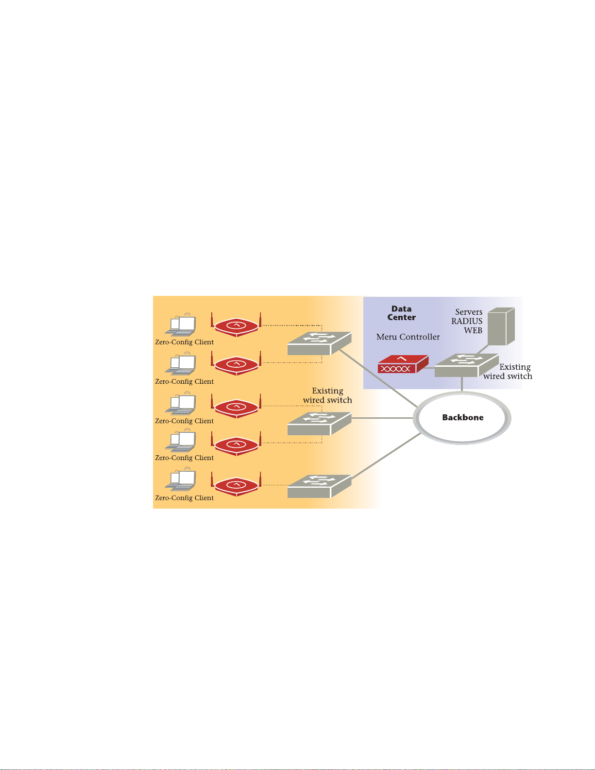
Access Points contain radio devices that communicate with the Meru Controller and
form the wireless LAN (WLAN). The Meru Controller and Access Points connect to the
site’s wired LAN through wired switches. Wireless clients associate with the Access
Points as they roam throughout the WLAN. As such, they are an extension of the wired
LAN, providing the wireless benefits of client mobility, enhanced access, and
dynamic network configuration.
Figure 1: Wireless LAN Connected to Network
© 2010 Meru Networks, Inc. Access Points 1

AP300
AP300
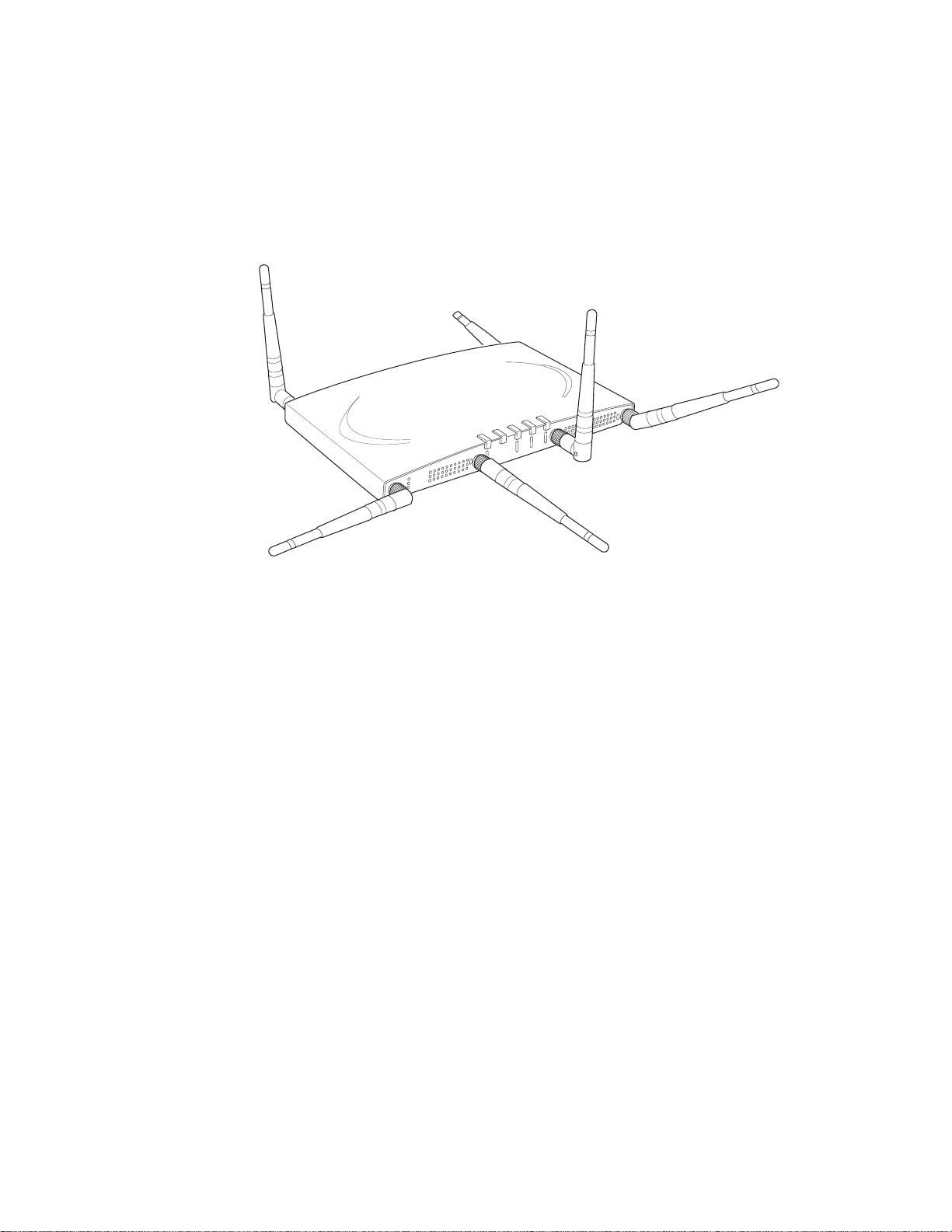
The AP300 Access Point series delivers high performance, full-speed, Wi-Fi certified
802.11n based on draft 2.0 connectivity while simultaneously supporting legacy
802.11a/b/g devices. AP300 is available in the configurations shown below.
AP300 Configurations
Model Configuration
AP320i
AP320
Two dual-band 802.11n radios with 3x3 MIMO and internal
antennas
Two dual-band 802.11n radios with 3x3 MIMO and external
antennas
Single dual-band 802.11n radio with 3x3 MIMO and external
AP310/AP310-M
AP311
AP302
AP301
antennas
Single dual-band 802.11n radio and single 802.11a/b/g
radio (AP320 upgradable) with external antennas
Two dual-band 802.11a/b/g radios (AP320 upgrade able)
with external antennas
Single dual-band 802.11a/b/g radio (AP310 up-gradeable)
with external antennas
Features for the AP300 include:
802.11n support with channel bonding in both 2.4GHz and 5GHz frequency bands.
Channel bonding combines two 20Mhz cha nnels into a single-wide 40Mhz channel
for increased throughput.
Dual-band external antenna options optimized for MIMO mode
Plug and Play deployment using centralized controller platforms
Multi-layered security including standard WPA2, 802.11i security such as
automatic traffic inspection
Each of these Access points may be powered by a standard 802.3af PoE device.
Air Traffic Control technology for 802.11n devices and legacy a/b/g devices
3x3 MIMO with 3 chains and 3 receive chains, delivering two spatial streams
For AP302 and AP311, the a/b/g radio software upgrades to 802.11n for maximum
investment protection.
Channel span architecture which requires no channel planning or configuration
Six standard multiband, omni-directional antennas for AP302, AP320 and AP311.
Three standard multiband, omni-directional antennas for AP310/AP310-M and AP301.
2 Meru Access Point Installation Guide © 2010 Meru Networks, Inc.
AP300
A
2
A
2
A
L
A
N
R
F
1
R
F
2
2
Powered by 5 volt DC input, 802.3af compliant PoE device, or draft 802.3at
compliant PoE device.
Figure 2: AP300
© 2010 Meru Networks, Inc. Access Points 3
AP320i
AP320i
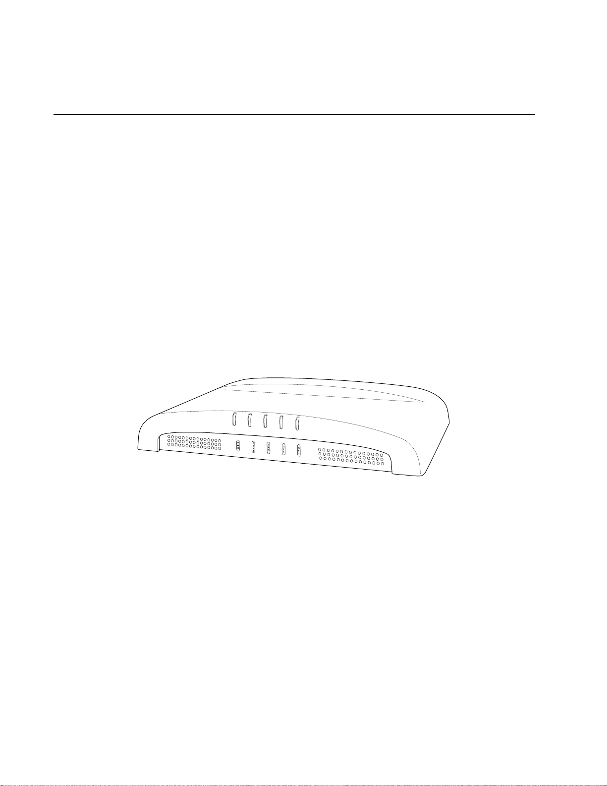
The AP320i Access Point is an internal-antenna AP with two dual-band 802.11n radios
and 3x3 MIMO and internal antennas.
Features for the AP320i include:
Internal antennas
802.11n support with channel bonding in both 2.4GHz and 5GHz frequency bands.
Channel bonding combines two 20Mhz channels into a single-wide 40Mhz channel
for increased throughput.
Plug and Play deployment using centralized controller platforms
Multi-layered security including standard WPA2 features such as automatic traffic
inspection
Standard 802.3af PoE support and support for many 802.3at devices
Air Traffic Control technology for 802.11n devices and legacy a/b/g devices
Channel span architecture that requires no channel planning or configuration
Figure 3: AP320i
4 Meru Access Point Installation Guide © 2010 Meru Networks, Inc.
AP200
AP200
00109
AP200
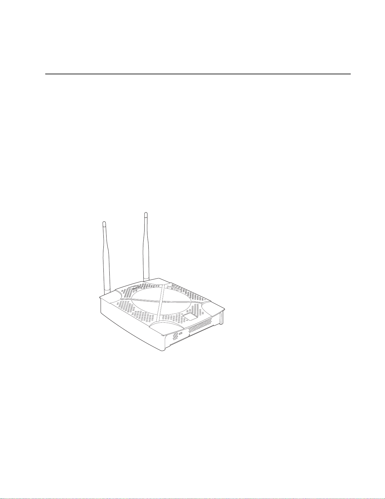
The AP200 series provides two models that conform to the specifications provided by
the IEEE 802.11a and 802.11g protocols and provide backward compatibility for the
802.11b protocol. An AP200 works with most standard Wi-Fi clients.
The AP201 houses a single 802.11a/b/g radio device.
The AP208 supports a maximum of two radio devices that can simultaneously run
two protocols (802.11b, g or b/g on interface 1 and 802.11a on interface 2).
Alternately the second radio can be configured to run as an RF monitor to a Meru
Controller, providing real-time status of RF activity to optimize the wireless
network.
The AP200 series (referred hereafter as the AP200, unless specifically referring to the
AP201 or AP208) is housed in a metal case with a plastic removable cover. As such, it
can be used for plenum installations when the plastic cover is removed.
Figure 4: AP200
© 2010 Meru Networks, Inc. Access Points 5
AP150
PWR
LAN
RADIO2
RADIO1
00175
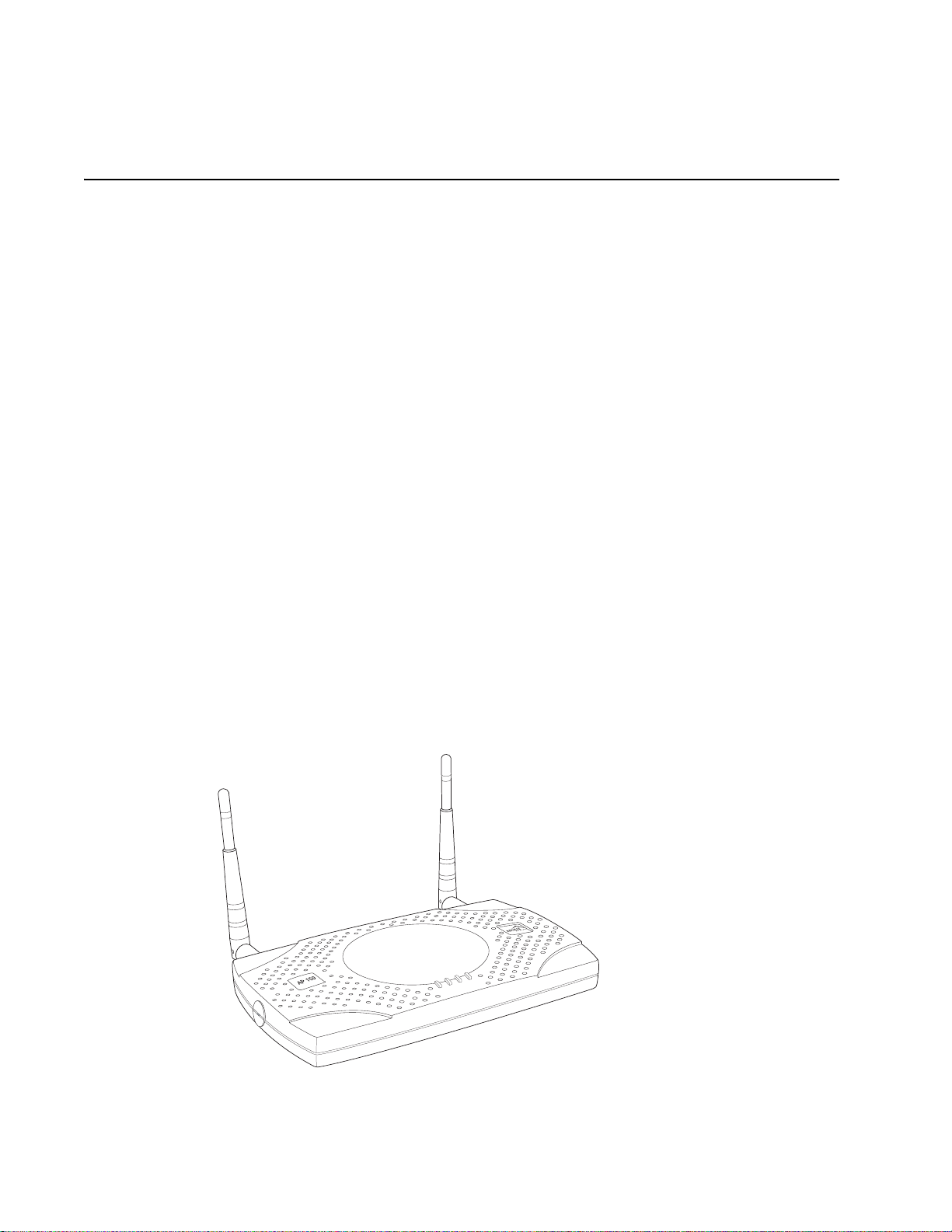
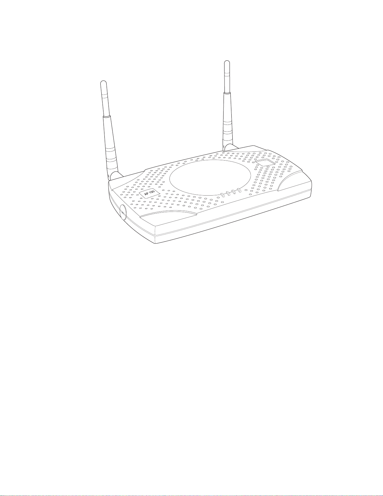
AP150
The AP150 has two 802.11 radios for simultaneous 802.11a and 802.11b/g WLAN
access. It is an ideal option for enterprise-wide data-only WLAN implementations and
small-sized converged data and voice WLAN implementations. The AP150 works in
conjunction with Meru Controller products and can be easily integrated into existing
Layer 2 and Layer 3 wired network environments to provide enterprise-grade Wi-Fi
access with multi-layered security options, basic VoWLAN support, centralized
configuration, troubleshooting tools, remote management and RF visualization capabilities.
The AP150 has the following features:
Dual 802.11b/g and 802.11a radios
Simultaneously support for 802.11b, 802.11g, and 802.11a clients
Contention Management for high density of data clients
Basic VoWLAN QoS support for small density of voice clients
Multiple ESSIDs with individual security policies to ensure separation of different
user groups or dynamic VLAN assignment per user based on RADIUS credentials
Zero configuration required at the access point; the installation procedure is a
simple plug-n-play
Automatic AP discovery, configuration
Intelligent load balancing of clients
Layer 2 or 3 connectivity for flexible deployment options
Locking mechanism secures access point when mounted in public areas
Figure 5: AP150
6 Meru Access Point Installation Guide © 2010 Meru Networks, Inc.
AP150
PWR
LAN
RADIO2
RADIO1
00175
© 2010 Meru Networks, Inc. Access Points 7
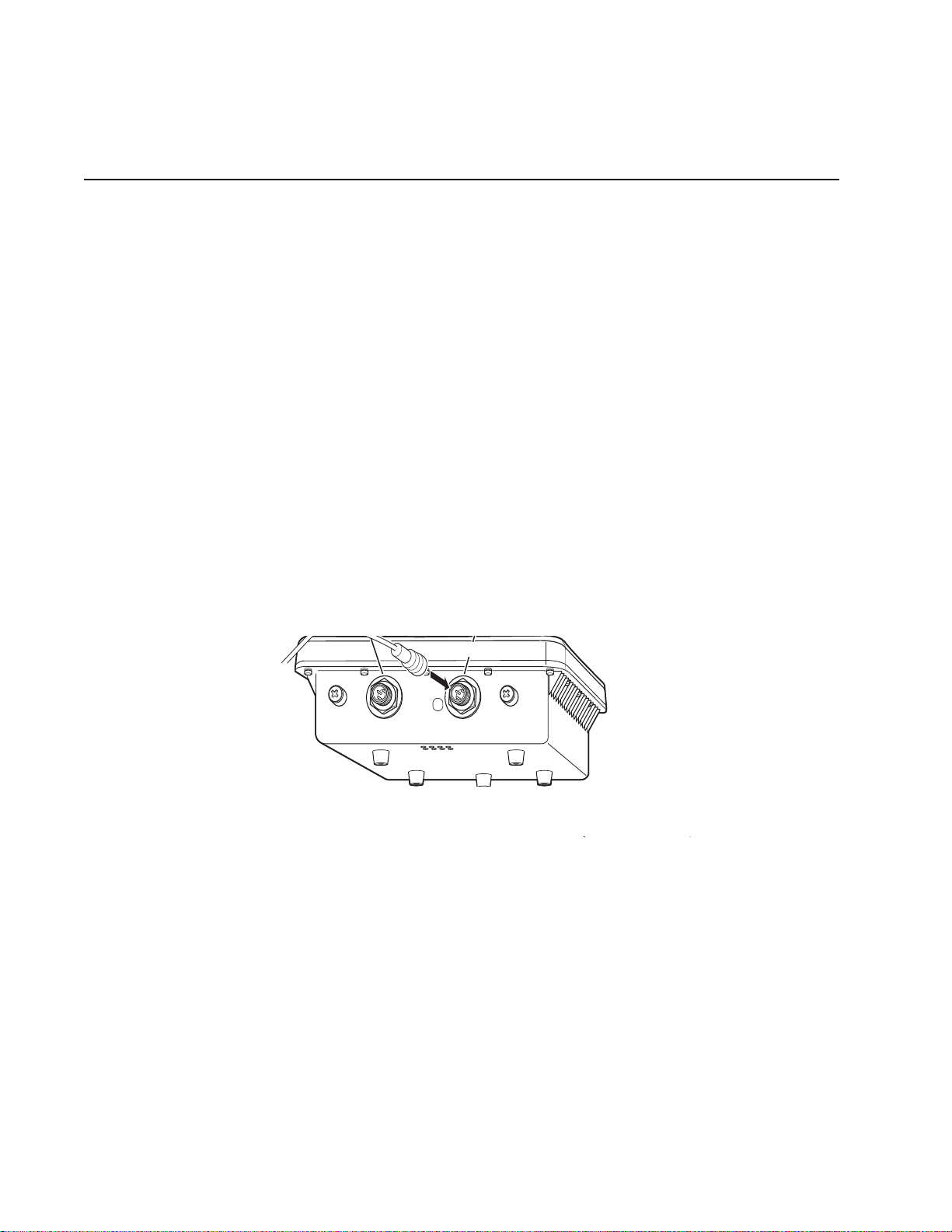
OAP180
Console PoE
Console Port PoE (Ethernet) Port
Ethernet
Cable
OAP180
The OAP180 Rugged Access Point with dual 802.11a/bg radios is designed to provide
secure Wi-Fi connectivity to outdoor locations such as campuses, parking lots, and
pole tops, or to harsh indoor locations such as breweries, food processing plants or
warehouses. The OAP180 supports the following features:
Simultaneous support for 802.11a, 802.11b, and 802.11g clients using dual
802.11a and 802.11b/g radios
Full support of System Director features
Automatic AP discovery and configuration
No channel planning required with single channel installations
Intelligent load balancing of clients
PoE (Power over Ethernet) support
RoHS compliant
Locking mechanism for security when mounted in public areas
Figure 6: Rugged OAP180 Access Point
8 Meru Access Point Installation Guide © 2010 Meru Networks, Inc.

OAP180
© 2010 Meru Networks, Inc. Access Points 9

OAP180
10 Meru Access Point Installation Guide © 2010 Meru Networks, Inc.

Safety Precautions
Chapter 2
Installing AP300
This chapter describes how to install and configure an AP300. It contains the following sections:
Safety Precautions
Unpack the AP300
Determine Power Requirements
Installation Requirements
Install the AP300
Check AP300 LED Activity
Check AP300 LED Activity
Where to Go From Here
Safety Precautions
IMPORTANT—Read and follow the regulatory instructions in Appendix B before installing and operating
this product.
If an optional power supply is used, it must be one supplied by Meru Networks.
The AP300 is intended only for installation in Environment A as defined in IEEE 802.3af. All interconnected equipment must be contained within the same building, including the interconnected equipment's associated LAN connection.
© 2010 Meru Networks, Inc. Installing AP300 11

Best Practices for an AP300/AP200 Network
Best Practices for an AP300/AP200 Network
Read this section if you have both AP200 and AP300 active simultaneously on the same network with ABG
legacy clients. The following best practices should be followed to get optimal performance from such a mixed
network.
Do not deploy AP200 and AP300 at the same physical location; we recommend no overlapping
coverage between AP200 and AP300.
If AP200 and AP300 must have overlapping coverage, make sure the ESS profiles on both AP types
are unique. The chart below shows two scenarios, one supported, one not supported.
AP300i and AP300 are interchangeable and fully compatible to share a virtual cell. It's like having
two AP300s with different antennas. The only difference is that AP300i is detected as a such in the
UI of the controller.
Supported Scenario AP200 Configuration AP300 Configuration
Two Unique ESS profiles
AP200 and AP300 SSID string
over the air
Unsupported Scenario AP200 Configuration AP300 Configuration
Same ESS profiles
AP200 and AP300 SSID string
over the air
Assumptions for the above best practices include:
AP200 is using Virtual Port and BSSID Virtual Cell (AP200 could also be using Shared BSSID Virtual
Cell.)
AP300 is using Virtual Port BSSID Virtual Cell.
AP200s and AP300s are on the same channel. (AP200 and AP300 could also be on different channels.)
AP200s and AP300s are on the same controller. (AP200 and AP300 could also be on different
controllers as long as each controller has a unique controller index.)
ESS Profile name in
controller is UniqueName1
Meru Meru
ESS Profile name in
controller is same name
Meru Meru
ESS Profile name in
controller is UniqueName2
ESS Profile name in
controller is same name
12 Meru Access Point Installation Guide © 2010 Meru Networks, Inc.

Unpack the AP300
The AP300 series has five models as shown below.
Model Radios
AP320 Two a/b/g/n
AP311 One a/b/g/n, one a/b/g
Unpack the AP300
AP310/AP310-M
AP302 One a/b/g
Confirm that the AP300 shipping package contains these items:
AP300 with attached mounting bracket
Six antennas
Screws for the mounting bracket
One a/b/g/n
© 2010 Meru Networks, Inc. Installing AP300 13

Determine Power Requirements
Determine Power Requirements
Power requirements vary, depending on which AP300 radios are deployed and what MIMO mode is used.
See the chart below for supported power sources for different radio configurations.
Radio 1 MIMO Radio 2 MIMO 802.3af PoE 802.3at PoE DC Power
2x2 2x2
2x2 3x3
3x3 2x2
3x3 3x3
Do not
recommend
Recommend
with caution
802.af PoE Usage
When using System Director 3.6/4.0 and 802.3af PoE, Meru supports radios set to any MIMO settings
except 3x3 on dual radios. This is because two radios set to 3x3 MIMO using an 802.3af switch may not
have enough power if the cable is too long. Shorter cables frequently work, however. Meru supports:
Single 3x3 radio
Dual 2 x 2 radios
Dual radio with one set to 2x2 and the other one set to 3x3
When using System Director 4.0 and 802.3af, the AP300 MIMO configuration is limited to the following:
3x3 for the 5 GHz radio
2x2 for the 2.4 GHz radio
802.3at PoE Usage
When using System Director 3.6/4.0 and 802.3at, the following radio combinations are recommended:
Single 3x3 radio
Dual 2 x 2 radios
Dual radio with one set to 2x2 and the other one set to 3x3
Dual 3x3 radios are recommended with a limitation. Use 802.3at power for two 3x3 MIMO radios
when the switch has a high enough power output to support all devices on the PoE. Calculate the
amount of power needed by each AP300/AP300i in 3x3 mode (13 watts), add that to power required
by other PoE devices on the switch and compare that value to the total power output from the
switch.
14 Meru Access Point Installation Guide © 2010 Meru Networks, Inc.

Installation Requirements
The calculation for 802.3at PoE use looks something like this:
(Number of AP300s * 13watts) + (sum of all other PoE devices power requirements) <= switch
power provided
Installation Requirements
An array of holes on the mounting bracket allows the AP300 to be mounted on the wall and over junction boxes or molly bolts. There are holes for passing the PoE Ethernet or external power supply cable
through the bracket if the bracket is mounted on a junction box. A template of this bracket is included
in Appendix E of this guide.
The AP300 has a security cable slot so you can lock the AP300 with a standard security cable, such as
those used to secure laptop computers.
Purchase optional mounting kits to mount the AP300 either from the ceiling or inside an enclosure:
Suspended Ceiling Rail Mounting Kit: ACC-MNT-SCRMKIT
Above Suspended Ceiling Mounting Kit (T-Bar Hanger): ACC-MNT-ASCMKIT
Inside a Hoffman Enclosure using Hoffman compatible mounting bracket: ACC-AP300-BHE (enclosure
not provided)
Above hanging ceiling tiles. Suitable for use in environmental air space in accordance with the
Section 300-22(c) of the National Electric Code and Sections 2- 128.12 - 010 (3) and 12 - 100 of the
Canadian Electrical Code. Part 1. C22. 1.
To complete AP300 installation, you need the items listed below.
Installation Type Items Required
Horizontal mounting None
Two #6 x 2" wood screws for a wood stud; or
Vertical mounting over a wall
stud
Vertical mounting on sheetrock
Horizontal mounting below a
hanging ceiling
Two #6 x 1½” metal screws for a metal stud
Mounting bracket
Two #6 x 1" screws
Two #4-6 x 7/8” ribbed plastic wall anchors
Mounting bracket
Two caddy fasteners
Two plastic spacers
Two keps nuts (with attached lock washer)
Mounting bracket
© 2010 Meru Networks, Inc. Installing AP300 15

Install the AP300
Installation Type Items Required
Using existing third party
brackets
Mounting above a ceiling tile
Use included shoulder screws
Tw o T - r ai l cl i ps
One T-box hanger
One bracket mounting clip
Mounting bracket
Additional Equipment
A power source is needed to power the AP300. See Determine Power Requirements.
Install the AP300
Select a Location
Attach the Provided Antennas
Install the Remote Antenna Mount (optional)
Install External ACC-ANT-MIMO-MNT Antenna with Three Connectors (optional)
Install Remote ACC-ANT-6ABGN-24 Antenna with Six Connectors (optional)
Install Antennas With One Connector (optional)
Install the Access Point
Select a Location
All AP300 interconnected equipment, including the associated LAN connection, must be contained
within the same building. In addition, the AP300 location should meet the following conditions:
Relatively unobstructed access to the stations the AP serves. Select a location with minimal physical
obstructions between the AP and the wireless stations. In an office with cubicles, mounting the APs
below a hanging ceiling (plenum is supported) or the wall near the ceiling provides the least
obstructed communications path. On a wall, orient the AP300 horizontally so that you can read the
Meru logo without tilting your head at 90 degrees - this orientation provides optimum MIMO
performance.
Access to wall outlet or a to a Power over Ethernet (PoE) connection to the network switch servicing
the controller.
AP300 is designed to provide 360 degree omni-directional coverage as illustrated below.
16 Meru Access Point Installation Guide © 2010 Meru Networks, Inc.

Install the AP300
ceiling
floor
Figure 8: Coverage Pattern for AP300 When Ceiling Mounted
Most installations receive the best coverage using the following guidelines:
Install APs toward the center of the building.
Place APs about 80 feet apart.
Do not install APs near metal objects, such as heating ducts, metal doors, or electric service panels.
For best coverage, orient antennas as shown in Figure 6.
Attach the Provided Antennas
All AP300s have six external antenna ports, labeled 1 - 6. These units operate with six antennas
attached, even though some configurations don’t use all six. Instead of attaching an antenna, you can
cap unused antenna connectors with 50 ohm Reverse Polarity SMA terminators. (For a list of approved
terminators, see http://www.merunetworks.com/merusupport
only for indoor use unless they are mounted in an outdoor enclosure (see Mount AP300 in a Hoffman
Enclosure). To achieve the best performance from your AP300, position antennas at a 90 degree angle
relative to each other as shown in Figure 6. The antennas do not have to be oriented exactly as shown
in the figure, but it is important to maintain the relative angles. If for some reason you are unable to
maintain those angles, the network still operates, but you may experience up to 20% drop in throughput
depending on the antenna orientation.
.) Meru supplied antennas are suitable
© 2010 Meru Networks, Inc. Installing AP300 17

Install the AP300
A
2
A
2
A
L
A
N
R
F
1
R
F
2
2
1 (horizontal)
6 (vertical)
2 (horizontal)
4 (horizontal)
3 (vertical)
5 (horizontal)
Figure 6: AP320, AP311 or AP302 Antennas 1-6 in Ceiling and Wall Mount Configuration
The following antenna connections are used during operation of the AP320, AP311, and AP302.
Table 1: AP300 Radios and Corresponding Antennas
Model Radio 1 (Ant4, Ant5, Ant6) Radio 2 (Ant1, Ant2, Ant3)
AP320
AP311
AP310/AP310-M
AP302
a/b/g/n with 3 dual band omni-directional
antennas
a/b/g/n with 3 dual band omni-directional
antennas
a/b/g/n with 3 dual band omni-directional
antennas
a/b/g with 3 dual band omni-directional
antennas
The AP310/AP310-M has six external antenna
three of those antennas and the unused antenna connectors are blocked.
Figure 7
illustrates the recommended antenna configuration for the AP310/AP310-M.
ports labeled 1 - 6. However, AP310/AP310-M uses only
a/b/g/n with 3 dual band omni-directional
antennas
a/b/g with 3 dual band omni-directional
antennas
NA
a/b/g with 3 dual band omni-directional
antennas
18 Meru Access Point Installation Guide © 2010 Meru Networks, Inc.

Figure 7: AP310/AP310-M Antennas 1-3
A
2
A
2
A
L
A
N
R
F
1
R
F
2
2
1 (horizontal)
2 (horizontal)
3 (vertical)
does not matter
does not matter
does not matter
Install the AP300
The following antenna connections are used during operation of the AP310/AP310-M.
Radio 1 Antenna Connectors for AP310/AP310-M Radio2 Antenna Connectors for AP310/AP310-M
Ant1, Ant2, Ant3 NA
Do not leave any antenna connectors unterminated. All connectors on the AP must be terminated with
antennas or with 50 ohm Reverse Polarity SMA terminators. (For a list of approved terminators, see
http://www.merunetworks.com/merusupport
.
The attached antennas must be the same model; if you replace one antenna, replace them all.
Install the Remote Antenna Mount (optional)
Use the optional Meru Remote Antenna Mount (ACC-ANT-MIMO-MNT) for one or both AP300 radios to
remotely connect the AP300 antennas. The Remote Antenna Mount allows you to relocate either your
current antennas or the optional high-gain dipole antennas to a location with clearer signal paths to
the other wireless devices in your network. The Remote Antenna Mount can be installed either below
the ceiling tile or on the wall. The default orientation for the mount is suitable for a ceiling mount,
but you can attach the mount to a wall with some modifications.
Use one mount per radio; for example AP310/AP310-M needs one unit, and AP320 needs two units.
The Remote Antenna Mount uses low-loss plenum rated LMR195 cable and SMA connectors.
To order this unit,
© 2010 Meru Networks, Inc. Installing AP300 19
contact your Meru sales representative and refer t
o part number ACC-ANT-MIMO-MNT.

Install the AP300
Figure 8: Remote Antenna Mount
00224
The remote antenna mount kit includes:
Antenna stand with attached cable. The three antenna SMA female connectors on the Antenna
Mount support AP300 antenna diversity. This feature gives the client the ability to automatically
choose the antenna receiving the strongest signal.
Triangular ceiling mount clip for attaching to hanging ceiling (includes bolt assembly)
Three self-adhesive pads for the bottom of the unit (over the screws)
Two wall mount screws with anchors
Ceiling Mount Template
Installation diagram
Install the Remote Antenna Mount on the Ceiling
To connect the Remote Antenna Mount to the ceiling, refer to the installation diagram from the shipping box while following these steps:
1. Attach the shorter end of the screw to the center hole on the back of the Antenna Mount.
2. Remove the designated ceiling tile.
3. Using the template, drill holes in the ceiling tile.
4. Replace the ceiling tile.
5. Remove a ceiling tile adjacent to the newly drilled tile for access purposes.
6. Feed the Antenna Mount cable through the larger hole in the ceiling tile until the Antenna Mount
is flush with the ceiling. The screw should now be visible above the ceiling tile (through the second
hole).
7. Place the triangular plate above the ceiling tile with the screw aligned through the plate.
8. Drop the washer onto the screw and tighten the bolt.
The Antenna Mount is now connected to the ceiling.
9. Replace the adjacent tile.
20 Meru Access Point Installation Guide © 2010 Meru Networks, Inc.

Install the AP300
Meru
A1
A5
A6
A4 A3 A2
10. Connect the three Remote Antenna Mount cables to the appropriate connectors on the AP300. Be
sure to connect the three antennas that correspond to one radio. Radio 1 uses A1, A2, A3 and Radio
2 uses A4, A5, A6.
11. Attach three antennas that shipped with AP300 to the three connectors on the triangular remote
device. See Figure 8.
© 2010 Meru Networks, Inc. Installing AP300 21

Install the AP300
Install the Remote Antenna Mount on a Wall
1. Reorient the cable on the Remote Antenna Mount by removing the three screws on the back,
removing the small cover, reorienting the cable and then replacing the three screws. Discard the
small cover.
2. Connect the three Remote Antenna Mount cables to the appropriate ports on the AP300. Be sure to
connect the three antennas that correspond to one radio.
and Radio 2 uses A1, A2, A3. For AP310/AP310-M, the single radio uses A1, A2, A3.
.
With dual radio, Radio 1 uses A4, A5, A6
A5
Meru
A4 A3 A2
A6
A1
3. Attach three of the antennas that shipped with AP300 to the three ports on the triangular remote
device.
4. Orient the connected AP300 horizontally so that you can read the Meru logo without tilting your
head at 90 degrees - this orientation provides optimum MIMO performance.
Install External ACC-ANT-MIMO-MNT Antenna with Three Connectors (optional)
You can optionally use an external antenna setup with your AP300 if the controller and APs are running
System Director 3.6.1MR4 and later. Meru supports this antenna for use on one radio using 802.11n
MIM
O. An AP300 with one radio, for example AP310/AP310-M, needs one antenna. An AP300 with two
radios, for
Two cables connect to ports A4, A5, and A6. There is no preferred cabling connection; all three cables
are the same.
enO oidaR .sannetna owt sdeen ,023PA elpmaxe cables connect to ports A1, A2, and A3. Radio
Calculate the antenna gain for the ACC-ANT-MIMO-MNT antenna by referring to the next three charts:
Band of Operation Gain Vertical Beamwidth Horizontal Beamwidth
2.40-2.483 GHz 2.5dB 55 degrees 360 degrees
5.15-5.85 GHz 4dB 60 degrees 360 degrees
22 Meru Access Point Installation Guide © 2010 Meru Networks, Inc.

Using This Cable Type with 2.4 GHz Calculate This Loss per Foot
RG174 0.60 dB
RG316 0.48 dB
LMR100 0.39 dB
LMR200 0.17 dB
LMR240 0.13 dB
LMR400 0.066 dB
LMR600 0.043 dB
Using This Cable Type with 5 GHz Calculate This Loss per Foot
RG174 1.02
RG316 0.76
Install the AP300
LMR100 0.59 dB
LMR200 0.24 dB
LMR240 0.19 dB
LMR400 0.100 dB
LMR600 0.066 dB
© 2010 Meru Networks, Inc. Installing AP300 23

Install the AP300
Install Remote ACC-ANT-6ABGN-24 Antenna with Six Connectors (optional)
You can optionally use an external antenna setup with your AP300 if the controller and APs are running
System Director 3.6.1MR4 and later. Meru supports this antenna for use on AP300s with two radios, for
example AP320. This antenna has six connectors to connect to both radios to a dual-radio AP300 and
it supports 802.11n MIMO operation.
The six cables on the ACC-ANT-6ABGN-24 antenna are already tagged with the numbers 1 - 6. Connect
the antenna cables to the AP antenna ports as shown here:
Meru AP300 Antenna
Connector
A1 6
A2 5
A3 4
A4 3
Antenna Cable Numbered
A5 2
A6 1
A5
AP300
A3A4
A6
A2 A1
2
1
4
5
3
antenna
6
Calculate the antenna gain for the ACC-ANT-6ABGN-24 antenna by referring to the next three charts:
Band of Operation Gain Vertical Beamwidth Horizontal Beamwidth
2.40-2.483 GHz 2.5dB 55 degrees 360 degrees
5.15-5.85 GHz 4dB 60 degrees 360 degrees
24 Meru Access Point Installation Guide © 2010 Meru Networks, Inc.

Using This Cable Type with 2.4 GHz Calculate This Loss per Foot
RG174 0.60 dB
RG316 0.48 dB
LMR100 0.39 dB
LMR200 0.17 dB
LMR240 0.13 dB
LMR400 0.066 dB
LMR600 0.043 dB
Using This Cable Type with 5 GHz Calculate This Loss per Foot
RG174 1.02
Install the AP300
RG316 0.76
LMR100 0.59 dB
LMR200 0.24 dB
LMR240 0.19 dB
LMR400 0.100 dB
LMR600 0.066 dB
Install Antennas With One Connector (optional)
You can optionally use an external antenna setup with your AP300 if the controller and APs are running
System Director 3.6.1MR4 or 4.0.
When deploying an AP300 with only one antenna per radio, AP300 cannot support 802.11n MIMO oper-
ation. Also, any antenna ports that are not used to connect to an antenna must be terminated with 50
ohm Reverse Polarity SMA terminators. (For a list of approved terminators, see http://www.merunet-
works.com/merusupport.) Connect the antenna using one cable per radio as described in the table
below. These instructions can be used to replace an AP200 existing antenna configuration with an
AP300. For these instructions, each port on the AP300 is identified by a label A1 to A6.
© 2010 Meru Networks, Inc. Installing AP300 25

Install the AP300
Meru
A1
A5
A6
A4 A3 A2
(BG or A radio antenna)
Meru
A1
A5
A6
A4 A3 A2
(BG radio antenna)
(A radio antenna)
Meru
A1
A5
A6
A4 A3 A2
(BG or A radio antenna)
(BG or A radio antenna)
Meru
A1
A5
A6
A4 A3 A2
(BG radio antenna)
(A radio antenna)
(A radio antenna)
(BG radio antenna)
AP Has One BG or A Radio, One Antenna
AP Has Two Radios (BG and A), One Antenna For Each
AP Has One Radio, Two Antennas
AP Has Two Radios, Four Antennas
26 Meru Access Point Installation Guide © 2010 Meru Networks, Inc.

Install the AP300
Install the Access Point
AP300 ships with a detachable mounting bracket. The AP300 is d esigned to be compatible w i th brackets
supplied by Meru and by other vendors as follows. The AP300 mounts directly on the AP150 mounting
bracket. If you are replacing AP200s/AP300s, the AP300 bracket can be mounted on the old
AP200s/AP300s bracket with included shoulder screws; you don’t need to remove the old brackets.
AP300 can also be directly mounted on third-party brackets such as Proxim AP4000 and Cisco standard
brackets.
You can mount an AP300 in the following ways:
Mount AP300 Horizontally on a Shelf
Mount AP300 Vertically on a Wall
Mount AP300 Below a Suspended Ceiling
Mount AP300 Above a Suspended Ceiling (Plenum)
Mount AP300 in a Hoffman Enclosure
Mount AP300 Horizontally on a Shelf
When mounting an AP300 horizontally, remove the mounting bracket. Be sure to position the antennas
vertically when an AP300 sits on a surface.
Mount AP300 Vertically on a Wall
Note:
same bracket. If you are replacing AP300s, the AP300 bracket can be attached to the old bracket with
included shoulder screws; you don’t have to remove the old brackets. This bracket will also mount
seamlessly into the Proxim AP4000 bracket and standard Cisco brackets.
To mount an AP300 on a wall:
1. Using the bracket holes as a guide, mark the location on the wall for the two AP bracket mounting
2. Drill holes at the locations you marked:
3. If you are using plastic anchors, install them in the holes.
4. Screw in the screws most of the way.
5. Mount the bracket on the screws, placing the circular portion of the keyhole mounts over the screw
If you are replacing AP150s, you can use the existing brackets: the AP150 and AP300 use the
screws. If possible, center the mounting screws on a wall stud. If you do not center the mounting
screws on a wall stud, use plastic wall anchors. Orient the AP300 horizontally so that you can read
the Meru logo without tilting your head at 90 degrees - this orientation provides optimum MIMO
performance.
— 3/16-inch holes if you are using plastic anchors
— 1/8-inch holes if you are using only the screws
heads and sliding the bracket down.
6. Connect one end of the Ethernet cable to the switch and the other end to the AP300 Ethernet port.
© 2010 Meru Networks, Inc. Installing AP300 27

Install the AP300
Suspended ceiling T-rail
Mounting bracket
Keps nuts with attached
locking washer
Caddy fastener(s)
Plastic spacer(s)
00102
Caution!
Be sure to connect the Ethernet cable to the Ethernet port; the cable can
mistakenly be plugged into the Console port. If you do this, the AP won’t power up.
7. If you are not using a PoE device, connect an external power supply to the power connector and
plug it into the wall.
Mount AP300 Below a Suspended Ceiling
The optional suspended ceiling mounting kit (ACC-MNT-SCRMKIT) allows the AP300 mounting bracket
to attach to suspended ceiling T-rails (see Figure 9).
Note:
to the mounting bracket.
Figure 9: Mounting any AP to a Suspended Ceiling Rail using ACC-MNT-SCRMKIT
To comply with NEC code, attach a grounding wire to any of the screws used to attach the AP300
To mount an AP300 below a suspended ceiling:
1. Determine the location on the ceiling rail where the AP will be mounted and remove the ceiling
tiles.
2. Place each of the two caddy fasteners on the ceiling T-rail and twist to attach to the rail.
3. Adjust the distance between the caddy fasteners by using the mounting bracket holes as a guide.
4. Tighten the caddy fasteners in place using a standard screwdriver. Do not overtighten.
5. Place each spacer on the caddy fastener stud. The spacer legs should contact the ceiling T-rail.
6. Align the mounting bracket keyholes with the caddy fastener studs and slide the AP300 to the
narrow end of the hole.
7. Attach a keps nut to each caddy fastener stud and hand tighten. Do not overtighten.
28 Meru Access Point Installation Guide © 2010 Meru Networks, Inc.

Install the AP300
8. Align the AP300 mounting posts over the circular portion of the keyhole mounts, push the AP in and
slide the AP down until it engages with the locking detents (see Figure 9). You should hear it snap
in place.
9. For each antenna, loosen the knurled ring at the base of the antenna, orient the antenna and then
retighten the ring.
10. Connect one end of the PoE 100BaseT Ethernet cable to the 100/1000 Ethernet connector.
Caution!
Be sure to connect the Ethernet cable to the Ethernet port; the cable can
mistakenly be plugged into the Console port. If you do this. the AP won’t power up.
© 2010 Meru Networks, Inc. Installing AP300 29

Install the AP300
00243
00233
Mount AP300 Above a Suspended Ceiling (Plenum)
Use the optional T-bar box hanger mounting kit (see Mounting Brackets for the part number) to mount
AP300 above suspended ceiling T-rails (see Figure 10 and Figure 11). The installation attaches the Tbar box hanger to the ceiling rails and then the AP300 attaches to the T-bar box hanger. We recommend
that you mount the AP300 no more than half way up the supports as shown in both Figure 10 and
Figure 11. Also note that AP300 mounted above the ceiling has about 2-3 dBm less RF coverage than
AP300 mounted under the ceiling.
Figure 10: AP300 Mounted Above a Suspended Ceiling Face Down
The second example above is mounted too high on the support rails, which could cause the rails to
bend.
30 Meru Access Point Installation Guide © 2010 Meru Networks, Inc.

Figure 11: AP300 Mounted Above a Suspended Ceiling Face Up
00232
Install the AP300
The AP300 with the metal enclosure exposed meets the requirements for fire resistance and low
smoke-generating characteristics required by Section 300-22(C) of the National Electrical Code (NEC)
for installation in a building’s environmental air space.
You may need to modify thicker tiles to support this installation.
Warning!
When installed in air-handling spaces, such as above a suspended ceiling,
power the AP300 only with a PoE, not a power supply. See Power Supplies for part
numbers.
Warning!
Any Fast Ethernet (FE) cables installed in air-handling spaces should be
suitable under NEC Article 800.50 and marked accordingly for use in plenums and airhandling spaces with regard to smoke propagation, such as CL2-P, CL3-P, MPP (Multi
Purpose Plenum), or CMP (Communications Plenum). Use Ethernet cable that meets
the requirements for operating in plenums and environmental air space in
accordance with Section 300-22(C) of the NEC.
© 2010 Meru Networks, Inc. Installing AP300 31

Install the AP300
00104
00104
To mount an AP300 above the ceiling with the optional T-bar kit, follow these steps:
1. Determine the location on the ceiling rails where the AP will be mounted and remove the ceiling
tile.
2. Unpack the T-bar hanger kit and unfold the legs of the T-bar hanger.
3. Locate the bracket mounting clip holes on the mounting bracket (see Figure 10). One hole attaches
the bracket perpendicular to the box hanger; the other mounts the bracket parallel to the box
hanger.
4. Attach the U-joint of the clip to the T-bar and snap in place (see Figure 12).
Figure 12: Attaching the Mounting Bracket to the Box Hanger for Face Up Orientation
.
Figure 13: Attaching the Mounting Bracket to the Box Hanger for Face Down Orientation
.
5. Pass the long end clip through the large center hole to the underside of the mounting bracket clip
and then attach the bracket to the clip using the supplied screw (see Figure 12 for orientation).
32 Meru Access Point Installation Guide © 2010 Meru Networks, Inc.

Install the AP300
6. Hold the AP300 next to the mounting bracket to estimate the height of the T-bar box hanger. You
need to provide enough clearance for the external antennas that point down, while mounting the
T-bar on the lower half of the support rails for stability.
7. Adjust the height of the box hanger using the height adjusting screws (see Figure 9).
8. Clip the box hanger T-rail clips to the ceiling rails, making sure they are securely attached.
9. Connect a drop wire to a building structural element and through the hole provided in the bracket
mounting clip. The U.S. National Electrical Safety Code requires this additional support.
10. Connect the posts of the AP300 to the three keyholes of the mounting bracket and slide into the
keyhole, ensuring the locking detent is engaged. You will hear a click.
11. For each antenna, loosen the knurled ring at the base of the antenna, point the antenna down, then
retighten the ring.
12. Connect one end of the PoE Ethernet cable to the Ethernet connector.
Caution!
mistakenly be plugged into the Console port. If you do this. the AP won’t power up.
Note:
13. Check that the AP300 is operating correctly before replacing the ceiling tile to the ceiling. Verify
correct operating using the LEDs, as shown in Check AP300 LED Activity.
Be sure to connect the Ethernet cable to the Ethernet port; the cable can
Use a shielded Cat 5e (or greater) Ethernet cable in order to comply with
international electromagnetic emissions limits.
Mount AP300 in a Hoffman Enclosure
Meru has designed a custom mounting bracket compatible with a Hoffman enclosure (www.hoffmanonline.com). This bracket is available exclusively through Meru and orderable as part number ACC-AP300-
BHE. To mount an AP300 in a Hoffman enclosure, follow these steps:
1. Place AP300 upside down on a soft flat surface.
2. Remove and discard the wall/ceiling mounting bracket.
3. Attach either the provided antennas or an external antenna.
4. Remove and discard the four rubber feet.
5. Position the Hoffman bracket (ACC-AP300-BHE) onto the back of the AP300 with the four Hoffman
mounting screws facing downwards.
© 2010 Meru Networks, Inc. Installing AP300 33

Check AP300 LED Activity
A
3
A
2
L
A
N
S
T
T
A
P
W
R
R
F
1
R
F
2
00217
P
W
R
S
T
A
T
L
A
N
R
F
1
R
F
2
Figure 14: Hoffman Bracket ACC-AP300-BHE
00230
6. Using a Phillips screw driver, attach the bracket using the two supplied 6-32 3/16 SEMS screws.
7. Flip the assembly over and mount into the Hoffman enclosure, attach the Ethernet cable to the
AP300 rotating the assembly to place the Ethernet cable within the enclosure.
8. Using a Phillips screw driver, tighten the four bracket screws to the enclosure.
9. Adjust the antennas as needed.
Check AP300 LED Activity
When AP300 first connects to the controller (and any time the access point is rebooted), the AP initializes and is then programmed by the controller. When the AP first powers up, all LEDs are green.
Figure 15: AP300 Status LEDs
After the AP300 is connected, check the status of the LEDs. The functions of the five LEDs are described
below.
34 Meru Access Point Installation Guide © 2010 Meru Networks, Inc.

Check AP300 LED Activity
AP300/AP300i LED Descriptions
LED Function Troubleshooting
Power
Status
LAN
off—no power
green—presence of power
off—no power
green—booting stage 1
blinking green and off—booting stage 2
blinking green and white—discovering the
controller
blinking green and blue—downloading a
configuration from the controller
blinking blue and off—AP is online and
enabled, working state
blinking red and yellow—failure; consult
controller for alarm state
off—no power or no link
green—link status OK (at any speed)
green/blinking—activity (at any speed)
red—auto negotiation failure
If the status LED is blinking red and
yellow, there is an alarm on the AP.
Determine what the alarm is by
clicking Monitor > Dashboard >
Alarms and looking at the AP alarms.
You can also use the CLI commands
show alarm and show log.
If the LAN LED is red, auto
negotiation failed. This means that
you have a problem with cabling or
with the AP’s switch.
If one of the radio LEDs is yellow, it is
either disabled or in scanning mode.
To see if the AP is disabled, click
Configuration > Wireless > Radio >
select a radio and then look at
Administrative Status, which should
off—no radio present
Radio 1
Radio 2
© 2010 Meru Networks, Inc. Installing AP300 35
green—radio enabled
green blinking—data activity
yellow—disabled or in scanning mode
red—failure
be set to Up. To see if the AP is in
Scanning Mode, click Configuration >
Wireless > Radio > select a radio and
look at AP Modes, which should be set
to Normal Mode.
If one of the radio LEDs is red, the
radio failed. Check the alarms
(Monitor > Dashboard > Alarms),
diagnostics (Monitor > Diagnostics >
Radio), and statistics (Monitor >
Dashboard > Radio) on the AP’s
controller to determine the cause.

Where to Go From Here
Where to Go From Here
Now that the AP300 is installed, refer to the Meru System Director Getting Started Guide for instructions on initializing the hardware. Return to this chapter to check the status of the LEDs once the WLAN
is operational.
36 Meru Access Point Installation Guide © 2010 Meru Networks, Inc.

Safety Precautions
Chapter 3
Installing AP320i
AP320i is supported by System Director versions 3.6.1 and greater, but full support begins with System
Director release 4.0. Because of this, when using AP320i with System Director 3.6.1, the unit shows as
an AP300, for example AP320 instead of AP320i. All AP320i units still function correctly, they just
display as AP300 because AP320i did not exist when System Director 3.6.1 was released.
This chapter describes how to install and configure an AP320i. It contains the following sections:
Safety Precautions
Unpack the AP320i
Determine Power Requirements
Installation Requirements
Installing AP320i
Check AP320i LED Activity
Where to Go From Here
Safety Precautions
IMPORTANT—Read and follow the regulatory instructions in Appendix B before installing and operating
this product.
If an optional power supply is used, it must be one supplied by Meru Networks.
The AP320i is only intended for installation in Environment A as defined in IEEE 802.3af. All interconnected equipment must be contained within the same building, including the interconnected equipment's associated LAN connection.
© 2010 Meru Networks, Inc. Installing AP320i 37

Best Practices for an AP320i/AP200 Network
Best Practices for an AP320i/AP200 Network
Read this section if you have both AP200 and AP320i active simultaneously on the same network. The
following best practices should be followed to get optimal performance from such a mixed network.
Do not deploy AP200 and AP300/AP320i at the same physical location; we recommend that there be
no overlapping coverage between AP200 and AP300.
If AP200 and AP300/AP320i do have overlapping coverage, make sure the ESS profiles on both AP
types are unique. The chart below shows two scenarios, one supported, one not supported.
AP320i and AP300 are interchangeable and fully compatible to share a virtual cell. It's like having
two AP300s with different antennas. The only difference is that AP320i is detected as a such in the
UI of the controller.
Supported Scenario AP200 Configuration AP320i Configuration
Two Unique ESS profiles
AP200 and AP320i SSID string
over the air
Unsupported Scenario AP200 Configuration AP320i Configuration
Same ESS profiles
AP200 and AP320i SSID string
over the air
Assumptions for the above best practices include:
AP200 is using Virtual Port with BSSID Virtual Cell (AP200 could also be using Shared BSSID Virtual
Cell.)
AP320i is using Virtual Port with BSSID Virtual Cell.
AP200s and AP300s are on the same channel. (AP200 and AP320i could also be on different
channels.)
AP200s and AP320i is are on the same controller. (AP200 and AP320i could also be on different
controllers as long as each controller has a unique controller index.)
ESS Profile name in
controller is UniqueName1
Meru Meru
ESS Profile name in
controller is same name
Meru Meru
ESS Profile name in
controller is UniqueName2
ESS Profile name in
controller is same name
38 Meru Access Point Installation Guide © 2010 Meru Networks, Inc.

Unpack the AP320i
Unpack the AP320i
Confirm that the shipping box contains the following:
AP320i with an attached ceiling mounting bracket
Wall mount bracket with screws
Small locking key for ceiling or wall mount locking
Determine Power Requirements
Power requirements vary, depending on which AP300 radios are deployed and what MIMO mode is used.
See the chart below for supported power sources for different radio configurations.
Radio 1 MIMO Radio 2 MIMO 802.3af PoE 802.3at PoE DC Power
2x2 2x2
2x2 3x3
3x3 2x2
3x3 3x3
Do not
recommend
Recommend
with caution
802.af PoE Usage
When using System Director 3.6/4.0 and 802.3af PoE, Meru supports radios set to any MIMO settings
except 3x3 on dual radios. This is because two radios set to 3x3 MIMO using an 802.3af switch may not
have enough power if the cable is too long. Shorter cables frequently work, however. Meru supports:
Single 3x3 radio
Dual 2 x 2 radios
Dual radio with one set to 2x2 and the other one set to 3x3
When using System Director 4.0 and 802.3af, the AP300 MIMO configuration is limited to the following:
3x3 for the 5 GHz radio
2x2 for the 2.4 GHz radio
© 2010 Meru Networks, Inc. Installing AP320i 39

Installation Requirements
802.3at Usage
When using System Director 3.6/4.0 and 802.3at, the following radio combinations are recommended:
Single 3x3 radio
Dual 2 x 2 radios
Dual radio with one set to 2x2 and the other one set to 3x3
Dual 3x3 radios are recommended with a limitation. Use 802.3at power for two 3x3 MIMO radios
when the switch has a high enough power output to support all devices on the PoE. Calculate the
amount of power needed by each AP300/AP320i in 3x3 mode (13 watts), add that to power required
by other PoE devices on the switch and compare that value to the total power output from the
switch. The calculation for 802.3at PoE use looks something like this:
(Number of AP300s * 13watts) + (sum of all other PoE devices power requirements) <= switch
power provided
Installation Requirements
.
Installation Type Order These Additional Items
Horizontal mounting None
Vertical mounting over a wall
stud
Vertical mounting on sheetrock None
Horizontal mounting below a
hanging ceiling
Reusing an existing bracket from
another AP
None
None
For connection to Meru AP200 or AP150 only, order shoulder screws,
Meru part number 665-00012 (SCR, PIC.1/4*1/8 10-32 SKT SHLDR
SCR 303 STNLS). Connection to other brackets does not require this.
Additional Equipment
A power source is needed to power the AP300. See Determine Power Requirements. If you want to lock
an AP320i to the ceiling or wall, you need a small key like the ones used to lock suitcases.
40 Meru Access Point Installation Guide © 2010 Meru Networks, Inc.

Installing AP320i
Installing AP320i
Select a Location
All AP320i interconnected equipment must be contained within the same building, including the interconnected equipment's associated LAN connection. Ceiling mounting is recommended but wall
mounting is also supported. In addition, the AP320i should be mounted in a location that meets the
following conditions:
Relatively unobstructed access to the stations the AP serves. Select a location with minimal physical
obstructions between the AP and the wireless stations. In an office with cubicles, mounting the APs
below a hanging ceiling (plenum is supported) or the wall near the ceiling provides the least
obstructed communications path. On a wall, orient the AP300 horizontally so that you can read the
Meru logo without tilting your head at 90 degrees - this orientation provides optimum MIMO
performance.
Access to wall outlet or a to a Power over Ethernet (PoE) connection to the network switch servicing
the controller.
AP320i is designed to provide 180 degree omni-directional coverage as illustrated below. Plan placement with this pattern in mind.
Figure 16: Coverage Pattern for AP320i When Ceiling Mounted
ceiling
floor
Most installations receive the best coverage using the following guidelines:
Install APs toward the center of the building.
Place APs about 80 feet apart.
Do not install APs near metal objects, such as heating ducts, metal doors, or electric service panels.
If you install AP320i on a pole, keep in mind that coverage will be 180 degrees. Do not mount two
AP320is back to back on a pole to achieve 360 degree coverage, however, because the two units
could interfere with each other.
Install the Access Point
The AP320i ships with a detachable ceiling mounting bracket, making the unit ready for ceiling
mounting. You can also remove the ceiling-mount bracket and use the included wall-mount bracket.
The wall mount bracket can be attached to sheetrock, wall studs, or another wall bracket supplied by
Meru and by other vendors. If you are replacing AP200s/AP300 wall brackets, the AP320i bracket can
be mounted on top of the old AP200/AP300 bracket using shoulder screws (not included); you don’t
need to remove the old brackets. AP320i can also be directly mounted on standard third-party wall
© 2010 Meru Networks, Inc. Installing AP320i 41

Installing AP320i
brackets such as the Proxim AP4000 bracket and standard Cisco brackets. You cannot, however, mount
AP320i directly on an AP150 wall-mount bracket; in this case, you must remove and replace the AP150
bracket. Installation directions are provided below.
Mount AP320i in any of the following ways:
Mount AP320i On a Suspended Ceiling
Mount AP320i Above a Suspended Ceiling (Plenum)
Mount AP320i Vertically on a Wall
Set AP320i on a Shelf
Mount AP320i Below a Recessed Ceiling
42 Meru Access Point Installation Guide © 2010 Meru Networks, Inc.

Installing AP320i
T-bar
(in ceiling)
Mounting bracket Press this tab down
with T-bar.
AP300i
00235
g00240
LAN 5V DCCON
console Ethernet
Mount AP320i On a Suspended Ceiling
AP320i ships ready to mount on a suspended ceiling; the attached bracket clips to a ceiling rail.
To mount an AP320i below a suspended ceiling, follow these steps:
1. Determine the location on the ceiling rail where the AP will be mounted and remove the ceiling
tiles.
2. Align the mounting bracket with the slots indicated in Figure 17 below.
Figure 17: Install AP320i Below a Suspended Ceiling
3. Press down on the tab indicated in Figure 17 and rotate the AP320i into place.
4. Connect one end of the CAT5 (or greater) Ethernet cable to the 100/1000 Ethernet connector.
Caution!
Be sure to connect the Ethernet cable to the Ethernet port. The cable can
mistakenly be plugged into the Console port; if you do this, the AP won’t power up.
Figure 18: AP320i Ethernet Po rt on the Right
© 2010 Meru Networks, Inc. Installing AP320i 43

Installing AP320i
T-bar
(in ceiling)
Mounting bracket
AP300i
Security
clip
Lock security clip.Security clip fully inserted.
Insert security clip.
00236
5. Optionally install a small lock (not supplied) to secure the AP320i to the ceiling rail. See Figure 19.
To do this, you need the security key that shipped with the AP320i.
Figure 19: Optionally Install Your Own Lock on AP320i
Mount AP320i Above a Suspended Ceiling (Plenum)
AP320i is not plenum rated.
44 Meru Access Point Installation Guide © 2010 Meru Networks, Inc.

Installing AP320i
00234
Mount AP320i Vertically on a Wall
The AP320i ships with a ceiling mount bracket already connected to the unit and an additional separate
wall bracket. When wall mounting a unit, you will attach the wall mount bracket to the wall, then
attach the ceiling bracket (including AP320i) to the wall bracket. If you are replacing an AP200 or
AP150, the AP320i wall bracket can be mounted on top of the old bracket using shoulder screws (not
included - see Installation Requirements); you don’t need to remove the old brackets.If you are
replacing an AP300 or third-party brackets such as the Proxim AP4000 bracket and standard Cisco
brackets, the AP320i wall bracket can also be mounted on top of the old bracket (no additional screws
required).
To mount an AP320i on sheetrock or wall studs, follow these steps:
1. Using the wall bracket holes as a guide, mark the location on the wall for two AP bracket mounting
screws. Orient the connected AP300 horizontally so that you can read the Meru logo without tilting
your head at 90 degrees - this orientation provides optimum MIMO performance.
Figure 20: AP320i Wall Bracket
If possible, center the mounting screws on a wall stud. If you do not center the mounting screws on a
wall stud, use plastic wall anchors.
2. Drill holes at the locations you marked:
— 3/16-inch holes if you are using plastic anchors
— 1/8-inch holes if you are using only the screws
3. If you are using plastic anchors, install them in the holes.
4. Screw in the screws most of the way.
5. Mount the bracket on the screws, placing the circular portion of the keyhole mounts over the screw
heads and sliding the bracket down.
© 2010 Meru Networks, Inc. Installing AP320i 45

Installing AP320i
g00240
LAN 5V DCCON
console Ethernet
Wall bracket
(mounted
on wall)
Mounting
bracket
(attached)
AP300i
Tabs
Align tabs on Wall bracket
with tabs on the Mounting
bracket.
Twist to secure the
AP300i to the wall.
00237
6. Connect one end of the Ethernet cable to the switch and the other end to the AP320i Ethernet port.
Caution!
Be sure to connect the Ethernet cable to the Ethernet port. The cable can
mistakenly be plugged into the Console port; if you do this. the AP won’t power up.
Figure 21: AP320i Ethernet Port on the Right
7. If you are not using a PoE device, connect an external power supply to the power connector and
plug it into the wall.
8. Align the tabs on the wall bracket with the tabs on the ceiling bracket and then rotate the AP320i
clockwise to secure it to the wall. See Figure 22 below.
Figure 22: Mount AP320i on a Wall
46 Meru Access Point Installation Guide © 2010 Meru Networks, Inc.

Figure 23: Mount AP320i on an AP200 Wall Bracket
wall mount bracket
ceiling mount
bracket
AP300i
AP200 bracket on a wall
optional shoulder screw
Installing AP320i
9. Optionally, lock the AP320i bracket by inserting the provided locking key and applying a small lock.
Figure 24: AP320i Locked to a Wall
© 2010 Meru Networks, Inc. Installing AP320i 47

Check AP320i LED Activity
Push clip toward AP300i
to release the unit from
the wall bracket.
Mounting
bracket
AP300i
00238
Set AP320i on a Shelf
You can remove the mounting bracket(s) before setting AP320i on a shelf - see Figure 25.
Figure 25: Remove the AP320i Ceiling Mount Bracket
Mount AP320i Below a Recessed Ceiling
RECESSED CEILING MOUNT KIT???
Check AP320i LED Activity
When AP320i first connects to the controller (and any time the access point is rebooted), the AP initializes and then is programmed by the controller. When the AP first powers up, all LEDs are green. Thereafter, the Status LED color reflects the various operating states.
48 Meru Access Point Installation Guide © 2010 Meru Networks, Inc.

Check AP320i LED Activity
00239
power status LAN Radio 1 Radio 2
Figure 26: AP320i Status LEDs
After the AP320i is connected, check the status of the LEDs. The functions of the five LEDs are
described below.
© 2010 Meru Networks, Inc. Installing AP320i 49

Check AP320i LED Activity
AP300/AP320i LED Descriptions
LED Function Troubleshooting
Power
Status
LAN
off—no power
green—presence of power
off—no power
green—booting stage 1
blinking green and off—booting stage 2
blinking green and white—discovering the
controller
blinking green and blue—downloading a
configuration from the controller
blinking blue and off—AP is online and
enabled, working state
blinking red and yellow—failure; consult
controller for alarm state
off—no power or no link
green—link status OK (at any speed)
green/blinking—activity (at any speed)
red—auto negotiation failure
If the status LED is blinking red and
yellow, there is an alarm on the AP.
Determine what the alarm is by
clicking Monitor > Dashboard >
Alarms and looking at the AP alarms.
You can also use the CLI commands
show alarm and show log.
If the LAN LED is red, auto
negotiation failed. This means that
you have a problem with cabling or
with the AP’s switch.
Radio 1
Radio 2
off—no radio present
green—radio enabled
green blinking—data activity
yellow—disabled or in scanning mode
red—failure
If one of the radio LEDs is yellow, it is
either disabled or in scanning mode.
To see if the AP is disabled, click
Configuration > Wireless > Radio >
select a radio and then look at
Administrative Status, which should
be set to Up. To see if the AP is in
Scanning Mode, click Configuration >
Wireless > Radio > select a radio and
look at AP Modes, which should be set
to Normal Mode.
If one of the radio LEDs is red, the
radio failed. Check the alarms
(Monitor > Dashboard > Alarms),
diagnostics (Monitor > Diagnostics >
Radio), and statistics (Monitor >
Dashboard > Radio) on the AP’s
controller to determine the cause.
50 Meru Access Point Installation Guide © 2010 Meru Networks, Inc.

Where to Go From Here
Where to Go From Here
Now that the AP320i is installed, go to the Meru System Director Getting Started Guide for instructions
on initializing the hardware. Return to this chapter to check the status of the LEDs once the WLAN is
operational.
© 2010 Meru Networks, Inc. Installing AP320i 51

Where to Go From Here
52 Meru Access Point Installation Guide © 2010 Meru Networks, Inc.

Safety Precautions
Chapter 4
Installing AP200
This chapter describes how to physically install an AP200. It contains the following
sections:
Safety Precautions
Unpacking the AP200
Installation Requirements
Installing the Access Points
Where to Go From Here
Checking LED Activity
Safety Precautions
IMPORTANT—Read and follow the instructions in “Regulatory Information” on
page 109 before installing and operating this product.
Unpacking the AP200
As you unpack the AP200, confirm that the AP200 shipping package contains the items
listed on your packing list.
Shipments of the AP200 include a mounting bracket and mounting hardware for standard wall mounting. Optional mounting kits are available for mounting the AP200
above or below a hanging ceiling. The AP200 mounting studs are placed so they can
be used with brackets supplied by other vendors or to replace an AP100.
Note:
standard security cable, such as those used to secure laptop computers.
The AP200 has a security cable slot so you can secure the AP200 with a
© 2010 Meru Networks, Inc. Installing AP200 53

Installation Requirements
Access point mount
Ceiling mount hole
Ceiling mount hole
Access point mount
Access point mount
Locking detent
Wall cable access
Suspended ceiling
cable access
00100
An array of holes on the mounting bracket (see Figure 15) allows it to be mounted on
the wall and over junction boxes or molly bolts. There are also holes for passing the
PoE Ethernet or external power supply cable through the bracket if the bracket is
mounted on a junction box or over the ceiling T-bar box hanger.
Figure 15: AP200 Mounting Bracket
Installation Requirements
54 Meru Access Point Installation Guide © 2010 Meru Networks, Inc.
The following recommended mounting locations provide the best reception for the
AP200:
On a horizontal surface, such as a table or a desk
On a vertical surface, usually a wall
Below a hanging ceiling
Above a hanging ceiling tiles (this installation is supported only for the AP200 with
the plastic enclosure removed)
Warning!
environmental air space in accordance with the Section 300-22(c) of the National
With plastic covers removed, this product is suitable for use in
Electric Code and Sections 2- 128.12 - 010 (3) and 12 - 100 of the Canadian Electrical
Code. Part 1. C22. 1. For other countries, consult local authorities for regulations.

Installation Requirements
To complete this installation, you need the items listed below.
Installation Type Consumable Items Required
Horizontal mounting None
Two #6 x 2" wood screws for a wood stud; or
Vertical mounting over a wall
stud
Vertical mounting on sheetrock
Horizontal mounting below a
hanging ceiling
Two #6 x 1½" metal screws for a metal stud
Mounting bracket
Tw o # 6 x 1" s c r e ws
Two #4-6 x 7/8" ribbed plastic wall anchors
Mounting bracket
Two caddy fasteners
Two plastic spacers
Tw o k e p s n u t s ( w i t h a t tached lock washer)
Mounting bracket
Mounting above a ceiling tile
(AP200 metal enclosure only)
You need the tools listed below.
Tw o T - ra il c l ip s
One T-box hanger
One bracket mounting clip
Mounting bracket
© 2010 Meru Networks, Inc. Installing AP200 55

Installing the Access Points
AP200 Installation Tools
Installation Type Tools Required
Horizontal mounting None
Vertical mounting over a wall stud
Vertical mounting on sheetrock
Drill
1/8"drill bit
Screwdriver
Drill
3/16" drill bit
Screwdriver
Horizontal mounting below a hanging ceiling
Mounting above a hanging ceiling (AP200 metal
enclosure only)
Installing the Access Points
Selecting a Location
The AP200 requires a location that meets the following:
Relatively unobstructed access to the stations the AP serves
Power over Ethernet (PoE) connection to the network switch servicing the
controller.
APs can obtain their power from 802.3af standard Power over Ethernet (PoE)-compatible network switch or PoE power injector installed between the switch and the
AP200.
Screwdriver
Wrench or pliers
Wrench or pliers
Screwdriver
Select a location with minimal physical obstructions between the AP and the wireless
stations. In an office with cubicles, mounting the APs below a hanging ceiling or the
wall near the ceiling provides the least obstructed communications path. For an
external power supply connection, ensure the power source is near to where the
AP200 will be mounted.
Most installations receive the best coverage using the following guidelines:
Install APs toward the center of the building.
56 Meru Access Point Installation Guide © 2010 Meru Networks, Inc.

Installing the Access Points
Do not install APs near metal objects, such as heating ducts, metal doors, or
electric service panels.
Relative to the ground, orient the antenna up or down, not sideways.
Note:
environment. Place access points accordingly.
The AP200 is only intended for installation in Environment A as defined in IEEE
802.3af. All interconnected equipment must be contained within the same building,
including the interconnected equipment's associated LAN connection.
The previous guidelines are general guidelines. Each site has its own unique
Attaching the AP200 Antennas
The AP200 is provided with external antenna ports. Make sure that all external
antennas and their associated wiring are located entirely indoors. The external
antennas are not suitable for outside use.
If the AP200 does not have external antennas, attach the antennas to the connectors
on the AP200 (see Figure 16). Rotate the knurled ring at the base of the antenna
clockwise to attach the antenna. The ring should be finger-tight.
Caution!
knurled ring before moving the antenna. Retighten the ring afterward. Otherwise, you
might damage the internal cabling in the AP.
When changing the orientation of the antennas, be sure to slightly loosen the
Mounting the Access Point
You can mount an AP200 in the following ways:
Horizontally, as described in the “Horizontal Mounting” section.
Vertically, as described in the “Vertical Mounting” section.
Below a hanging ceiling, as described in the “Mounting Below a Suspended
Ceiling” section.
Above a tiled hanging ceiling, as described in the “Mounting Above a Suspended
Ceiling” section.
Horizontal Mounting
To horizontally mount an AP200:
1. Place the AP200 flat on the horizontal surface.
2. For each antenna, loosen the knurled ring at the base of the antenna (see
Figure 16), point the antenna straight up, then retighten the ring.
© 2010 Meru Networks, Inc. Installing AP200 57

Installing the Access Points
A
00110
0
(Currently
Figure 16: AP200 Antenna Connection
ntenna
3. Connect one end of the PoE 100BaseT Ethernet cable to the 100/1000 Ethernet
connector, shown in Figure 17.
ETHERNET
3.3 VDC
ANT 2
Turn clockwise
to tighten
For the AP201 and AP208 access points, a shielded Cat 5e (or greater)
Ethernet cable must be used in order to comply with international
Note:
electromagnetic emissions limits.
If it is not practical to use shielded cables, contact Support for a line filter,
available at no charge, that may also be used to ensure compliance.
Caution!
Be sure to connect the Ethernet cable to the Ethernet port; the cable can
mistakenly be plugged into the Console port (see Figure 17).
(Reserved)
Antenna 1 Antenna 2
Console
port
ANT 1
CONSOLE
Reset
(Push to restore
default settings)
100/1000
Ethernet
ETHERNET
unsupported)
Power
inlet
3.3 VDC
ANT 2
0108
58 Meru Access Point Installation Guide © 2010 Meru Networks, Inc.

Installing the Access Points
CONSOLE
ANT 1
ANT 2
3.3 VDC
ETHERNET
00108
100/1000
Ethernet
(Reserved)
Console
port
Antenna 1 Antenna 2
Power
inlet
Reset
(Push to restore
default settings)
(Currently
unsupported)
Ceiling mount hole
A
W
S
c
Figure 17: AP200 Connector Panel
Vertical Mounting
To vertically mount an AP:
1. Using the bracket holes as a template, mark the location on the wall for the two
AP bracket mounting screws. They are placed 4 ½ inches apart, center-to-center,
one above the other. If you are not using plastic wall anchors, you must center
the mounting screws on a wall stud. If you do not center the mounting screws on
a wall stud, you must use plastic wall anchors.
Figure 18: AP200 Bracket
Access point mount
all cable access
ccess point mount
uspended ceiling
able access
Ceiling mount hole
Locking detent
Access point mount
00100
© 2010 Meru Networks, Inc. Installing AP200 59

Installing the Access Points
00115
Mou nting b racket attached to wall
AP200
2. Drill holes at the locations you marked:
— 3/16-inch holes if you are using plastic anchors
— 1/8-inch holes if you are using only the screws
3. If you are using plastic anchors, install them in the holes.
4. Screw in the screws most of the way, so that the screw head is about 1/16 of an
inch from the wall.
5. Mount the bracket on the screws, placing the circular portion of the keyhole
mounts over the screw heads and sliding the bracket down.
6. Tighten the screws to secure the bracket.
7. Align the AP200 mounting posts over the circular portion of the keyhole mounts,
push the AP in and slide the AP down until it engages with the locking detents.
You should hear it snap in place.
60 Meru Access Point Installation Guide © 2010 Meru Networks, Inc.

Figure 19: Aligning the AP200 with the Br acket
Mounting bracket
Mounting bracket attached to wall
Installing the Access Points
AP200
00115
Figure 20: Sliding the AP200 into the Bracket
00112
8. For external antennas, loosen the knurled ring at the base of each antenna (see
Figure 16), point the antenna straight up, then retighten the ring.
9. Connect one end of the PoE 100BaseT Ethernet cable to the 100/1000 Ethernet
connector, shown in Figure 17.
© 2010 Meru Networks, Inc. Installing AP200 61

Installing the Access Points
Suspended ceiling T-rail
Mounting bracket
Keps nuts with attached
locking washer
Caddy fastener(s)
Plastic spacer(s)
00102
Note:
For the AP201 and AP208 access point, a shielded Cat 5e (or greater) Ethernet
cable must be used in order to comply with international electromagnetic
emissions limits.
Caution!
Be sure to connect the Ethernet cable to the Ethernet port; the cable can
mistakenly be plugged into the Console port.
Mounting Below a Suspended Ceiling
The optional suspended ceiling mounting kit allows the AP200 mounting bracket to
attach to suspended ceiling T-rails (see Figure 21).
Note:
to attach the AP200 to the mounting bracket.
Figure 21: Mounting the AP200 to a Suspended Ceiling Rail
To comply with NEC code, attach a grounding wire to any of the screws used
To mount an AP200 below a suspended ceiling:
1. Determine the location on the ceiling rail where the AP will be mounted and
remove the ceiling tiles.
2. Place each of the two caddy fasteners on the ceiling T-rail and twist to attach to
the rail.
3. Adjust the distance between the caddy fasteners by using the mounting bracket
holes as a guide.
62 Meru Access Point Installation Guide © 2010 Meru Networks, Inc.

Installing the Access Points
4. Tighten the caddy fasteners in place using a standard screwdriver. Do not
overtighten.
5. Place each spacer on the caddy fastener stud. The spacer legs should contact the
ceiling
T-rail.
6. Align the mounting bracket keyholes with the caddy fastener studs and slide the
AP200 to the narrow end of the hole.
7. Attach a keps nut to each caddy fastener stud and hand tighten. Do not
overtighten.
8. Align the AP200 mounting posts over the circular portion of the keyhole mounts,
push the AP in and slide the AP down until it engages with the locking detents
(see Figure 20). You should hear it snap in place.
9. For each antenna, loosen the knurled ring at the base of the antenna (see
Figure 16), point the antenna straight down, then retighten the ring.
10. Connect one end of the PoE 100BaseT Ethernet cable to the 100/1000 Ethernet
connector, shown in (see Figure 17).
For the AP201 and AP208 access points, a shielded Cat 5e (or greater)
Ethernet cable must be used in order to comply with international
Note:
electromagnetic emissions limits.
If it is not practical to use shielded cables, contact Support for a line filter,
available at no charge, that may also be used to ensure compliance.
Caution!
mistakenly be plugged into the Console port.
Be sure to connect the Ethernet cable to the Ethernet port; the cable can
Mounting Above a Suspended Ceiling
The optional T-bar box hanger mounting kit allows the AP200 to be mounted above
suspended ceiling T-rails (see Figure 22). The installation attaches the T-bar box
hanger to the ceiling rails using clips. The AP200 attaches to the mounting bracket
that is attached to the T-bar box hanger.
The AP200 antennas should point straight down for this type of installation. You may
need to modify thicker tiles to support this installation.
Warning!
the AP200 is to be powered via PoE only (PoE is required).
When installed in air-handling spaces, such as above a suspended ceiling,
© 2010 Meru Networks, Inc. Installing AP200 63

Installing the Access Points
Bracket mounting clip
Mounting bracket
T-bar hanger
Height adjustment screw
Height adjustment screw
Suspended ceiling T-rail
T-rail clips
Access Point
00103
Warning!
The AP200 with the metal enclosure exposed meets the requirements for
fire resistance and low smoke-generating characteristics required by Section 30022(C) of the National Electrical Code (NEC) for installation in a building’s
environmental air space. You must remove the plastic enclosure to reveal the
plenum-rated AP200 metal case for installations above a suspended ceiling.
Additionally, you must use Ethernet cable that meets the requirements for operating
in plenums and environmental air space (in accordance with Section 300-22(C) of the
NEC).
Warning!
Any Fast Ethernet (FE) cables installed in air-handling spaces should be
suitable under NEC Article 800.50 and marked accordingly for use in plenums and airhandling spaces with regard to smoke propagation, such as CL2-P, CL3-P, MPP (Multi
Purpose Plenum), or CMP (Communications Plenum).
Figure 22: Mounting the AP200 Above a Suspended Ceiling
64 Meru Access Point Installation Guide © 2010 Meru Networks, Inc.
To mount an AP200 above suspended ceiling rails:
1. Determine the location on the ceiling rails where the AP will be mounted and
remove the ceiling tile.
2. Unpack the T-bar hanger kit and unfold the legs of the T-bar hanger.
3. Locate the bracket mounting clip holes on the mounting bracket (see Figure 23).
One hole attaches the bracket perpendicular to the box hanger; the other mounts
the bracket parallel to the box hanger.

Installing the Access Points
Mounting bracket holes
00104
Figure 23: Box Hanger Mounting Bracket Holes
00101
4. Attach the U-joint of the clip to the T-bar and snap in place (see Figure 24).
Figure 24: Attaching the Mounting Bracket to the Box Hanger
.
5. Pass the long end clip through the large center hole to the underside of the
mounting bracket clip and then attach the bracket to the clip using the supplied
screw (see Figure 24 for orientation).
© 2010 Meru Networks, Inc. Installing AP200 65

Where to Go From Here
6. Hold the AP200 next to the mounting bracket to estimate the height of the T-bar
7. Adjust the height of the box hanger using the height adjusting screws (see
8. Clip the box hanger T-rail clips to the ceiling rails, making sure they are securely
9. Connect a drop wire to a building structural element and through the hole
10. Connect the posts of the AP200 to the three keyholes of the mounting bracket and
11. For each antenna, loosen the knurled ring at the base of the antenna (see
12. Connect one end of the PoE 100BaseT Ethernet cable to the 100/1000 Ethernet
box hanger to provide enough clearance for the external antennas, which should
be pointing down.
Figure 21).
attached.
provided in the bracket mounting clip. The U.S. National Electrical Safety Code
requires this additional support.
slide into the keyhole (see Figure 20), ensuring the locking detent is engaged. You
will hear a click.
Figure 16), point the antenna down, then retighten the ring.
connector, shown in Figure 17.
For the AP201 and AP208 access points, a shielded Cat 5e (or greater)
Ethernet cable must be used in order to comply with international
Note:
Note:
Caution!
mistakenly be plugged into the Console port.
13. Check that the AP200 is operating correctly before replacing the ceiling tile to
the ceiling. Verify correct operating using the LEDs, as shown in Checking LED
Activity.
electromagnetic emissions limits.If it is not practical to use shielded cables,
contact Support for a line filter, available at no charge, that may also be used
to ensure compliance.
For the AP201 and AP208 access points, a shielded Cat 5e (or greater)
Ethernet cable must be used in order to comply with international
electromagnetic emissions limits.
Be sure to connect the Ethernet cable to the Ethernet port; the cable can
Where to Go From Here
Now that the AP200 is installed, go to the Meru System Director Getting Started
Guide for instructions on initializing the hardware. Return to this chapter to check
the status of the LEDs once the WLAN is operational.
66 Meru Access Point Installation Guide © 2010 Meru Networks, Inc.

Checking LED Activity
Ethernet activity
Link present
00129
AP200
RF2
RF1
STATUS
POWER
00113
Access point status LEDs are provided on the Ethernet connector and on the face of
the AP200.
Ethernet Connector LEDs
After the AP200 is connected, the LEDs near the RJ-45 connector should light, as
shown in Figure 25.
Figure 25: RJ-45 LEDs
Checking LED Activity
The green LED on the left blinks if any Ethernet activity is taking place. If there is
no Ethernet activity, the LED is off. The LED on the right is solid green if an Ethernet
link is present. If no Ethernet link is present or connectivity is lost, the LED is off.
AP200 Status LEDs
Four status LEDs on the face of the AP200 also light, as shown in Figure 26.
© 2010 Meru Networks, Inc. Installing AP200 67

Checking LED Activity
AP200
RF2
RF1
STATUS
POWER
00113
Figure 26: AP200 Status LEDs
. .
The functions of the status LEDs are described below.
When the AP200 is first connected to the controller and any time the access point is
rebooted thereafter, the AP initializes with and then is programmed by the
controller. When the AP is first powered up, all LEDs are green. Thereafter, the
Status LED (see Figure 26) color reflects the various operating states as described in
the second table below.
68 Meru Access Point Installation Guide © 2010 Meru Networks, Inc.

AP200 LED Descriptions
LED Function
The status LED for Radio 2 is a follows:
off—no radio present
RF 2
RF 1
yellow—radio initializing
red—radio failure
solid green—radio OK
blinking green—radio activity
The status LED for Radio 1 is a follows:
off—no radio present
yellow—radio initializing
red—radio failure
solid green—radio OK
blinking green—radio activity
Checking LED Activity
Status AP-Controller operational status (see Table )
Power green—presence of power
AP200 Controller Status Information
State Interpretation AP200 LED Cycle
In the process of discovering the
controller. The AP is connected but not
associated with the controller. If the AP
Attempting to
discover Controller
Connected Normal operation without security.
does not associate with the controller
after a period of time, verify that the
connection between the AP and the
switch or the switch and the controller
is unbroken.
Green/Red/Blue/R
ed
Blue/Blue/Blue/Re
d
Blue/Blue/Blue/Re
d, for 2 seconds.
Authenticated Normal operation with security. Blue blink
© 2010 Meru Networks, Inc. Installing AP200 69
a

Checking LED Activity
State Interpretation AP200 LED Cycle
Access point was once connected to a
Disconnected
controller and configured by the
controller, but can no longer find that
Green/Purple/
Green/Purple
controller
Standalone Remote
Downloading
Error State
a. The AP200 LEDs cycle from bright to dim for each “blink.”
Access point is operating in a
standalone mode
Downloading image or configuration
from the controller
Access point is in an error state.
Call Meru technical support
Purple blink
Green/Blue
Green/Blue
Red (blinking or
solid)
70 Meru Access Point Installation Guide © 2010 Meru Networks, Inc.

Safety Precautions
Chapter 5
Installing AP150
This chapter describes how to physically install an AP150. It contains the following
sections:
Safety Precautions
Unpacking the AP150
Installation Requirements
Installing the Access Points
Where to Go From Here
Checking LED Activity
Safety Precautions
IMPORTANT—Read and follow the instructions in Appendix , “Regulatory Information”
on page 109 before installing and operating this product.
This product is intended to be supplied by a UL Listed power supply, marked Class 2
or LPS, and rated minimum 5 Vdc, 3A.
Caution!
in the plenum space.
The AP150 is not certified for plenum installations, and should not be installed
Unpacking the AP150
Confirm that the AP150 shipping package contains the AP150 access point with
attached mounting bracket.
© 2010 Meru Networks, Inc. Installing AP150 71

Installation Requirements
Figure 27: AP150 with Mounting Bracket
Installation Requirements
If you choose not to use the AP150 mounting bracket, the backside of the AP150
contains two keyholes to accommodate a simple wall mount.
A mounting bracket can be used for many wall mounting configurations. The AP150
bracket mounting studs are placed so they can be used with brackets supplied by
other vendors or to replace an AP100. An array of holes on the mounting bracket (see
Figure 27) allow it to be mounted on the wall and over junction boxes or molly bolts.
There are also holes for passing the PoE Ethernet or external power supply cable
through the bracket if the bracket is mounted on a junction box.
Additional optional mounting kits are available for mounting the AP150 above or
below a hanging ceiling, using the mounting bracket.
00177
72 Meru Access Point Installation Guide © 2010 Meru Networks, Inc.

Installation Requirements
Caution!
The AP150 is not certified for plenum installations, and should not be installed
in the plenum space.
Note:
The AP150 has two security cable slots (one on each side of the AP150) so you
can secure the AP150 with a standard security cable, such as those used to secure
laptop computers.
The following recommended mounting locations provide the best reception for the
AP150:
On a horizontal surface, such as a table or a desk
On a vertical surface, usually a wall
Below a hanging ceiling
Above hanging ceiling tiles
Suitable for use in environmental air space in accordance with the Section 30022(c) of the National Electric Code and Sections 2- 128.12 - 010 (3) and 12 - 100
of the Canadian Electrical Code. Part 1. C22. 1.
To complete this installation, you need the items listed in Table .
© 2010 Meru Networks, Inc. Installing AP150 73

Installation Requirements
AP150 Installation Items
Installation Type Consumable Items Required
Horizontal mounting None
Vertical mounting over a wall stud
Vertical mounting on sheetrock
Horizontal mounting below a
hanging ceiling
Two #6 x 2" wood screws for a wood stud; or
Two #6 x 1½” metal screws for a metal stud
Mounting bracket
Two #6 x 1" screws
Two #4-6 x 7/8” ribbed plastic wall anchors
Mounting bracket
Two caddy fasteners
Two plastic spacers
Two keps nuts (with attached lock washer)
Mounting bracket
Mounting above a ceiling tile
You need the tools listed below.
Tw o T - ra il c l ip s
One T-box hanger
One bracket mounting clip
Mounting bracket
74 Meru Access Point Installation Guide © 2010 Meru Networks, Inc.

AP150 Required Tools
Installation Type Tools Required
Horizontal mounting None
Drill
Vertical mounting over a wall stud
Vertical mounting on sheetrock
Horizontal mounting below a
hanging ceiling
1/8”drill bit
Screwdriver
1/8”Allen wrench
Drill
3/16” drill bit
Screwdriver
1/8”Allen wrench
Screwdriver
Wrench or pliers
1/8”Allen wrench
Installing the Access Points
Wrench or pliers
Mounting above a hanging ceiling
Screwdriver
1/8”Allen wrench
Installing the Access Points
Selecting a Location
The AP150 requires a location that meets the following criteria:
Relatively unobstructed access to the stations the AP serves
Power over Ethernet (PoE) connection to the network switch servicing the
controller.
APs can obtain their power from 802.3af standard Power over Ethernet (PoE)-compatible network switch or PoE power injector installed between the switch and the
AP150.
AP150 and AP300 work with all switches that support STANDARD 802.3af.
© 2010 Meru Networks, Inc. Installing AP150 75

Installing the Access Points
Select a location with minimal physical obstructions between the AP and the wireless
stations. In an office with cubicles, mounting the APs below a hanging ceiling or the
wall near the ceiling provides the least obstructed communications path. For an
external power supply connection, ensure the power source is near to where the
AP150 will be mounted.
Most installations receive the best coverage using the following guidelines:
Install APs toward the center of the building.
Do not install APs near metal objects, such as heating ducts, metal doors, or
electric service panels.
Relative to the ground, orient the antenna up or down, not sideways.
Note:
environment. Place access points accordingly. Note that the AP300 Power Adaptor
can also be used for AP150.
The AP150 is only intended for installation in Environment A as defined in IEEE
802.3af. All interconnected equipment must be contained within the same building,
including the interconnected equipment's associated LAN connection.
The previous guidelines are general guidelines. Each site has its own unique
Attaching the AP150 Antennas
The AP150 is provided with external antenna ports. Make sure that all external
antennas and their associated wiring are located entirely indoors. The external
antennas are not suitable for outside use.
If the AP150 does not have external antennas, attach the antennas to the connectors
on the AP150 (see Figure 28). Rotate the knurled ring at the base of the antenna
clockwise to attach the antenna. The ring should be finger-tight.
Caution!
knurled ring before moving the antenna. Retighten the ring afterward. Otherwise, you
might damage the internal cabling in the AP.
When changing the orientation of the antennas, be sure to slightly loosen the
Mounting the Access Point
You can mount an AP150 in the following ways:
Horizontally, as described in the “Horizontal Mounting” section.
Vertically, as described in the “Vertical Mounting with the Mounting Bracket”
section.
Below a hanging ceiling, as described in the “Mounting Below a Suspended
Ceiling” section.
Note that the AP300 Power Adaptor can also be used for AP150.
Above a tiled hanging ceiling with the optional ceiling mounting kit.
76 Meru Access Point Installation Guide © 2010 Meru Networks, Inc.

Installing the Access Points
00172
ANT 2
RELOAD
RESET
Turn clockwise
to tighten
Antenna
0
Antenna 1 Antenna 2
Horizontal Mounting
To horizontally mount an AP150:
1. Place the AP150 flat on the horizontal surface.
2. For each antenna, loosen the knurled ring at the base of the antenna (see
Figure 28), point the antenna straight up, then retighten the ring.
Figure 28: AP150 Antenna Connection
3. Connect one end of the PoE 100BaseT Ethernet cable to the 100/1000 Ethernet
connector, shown in Figure 29.
Figure 29: AP150 Connector Panel
Power Ethernet
(reserved)
ANT1 ANT2
DC 5V
connection
LAN
Vertical Mounting the AP150
To perform a simple wall mount using the keyholes on the back of the AP150:
1. Remove the attached mounting bracket from the back of the AP150.
Console
port
(reserved)
CONSOLE
Reset
Reload
button
RESET RELOAD
0173
© 2010 Meru Networks, Inc. Installing AP150 77

Installing the Access Points
2. Mark the location on the wall for two mounting screws. They are placed 4.3"
apart, center-to-center, or one above the other. If you are not using plastic wall
anchors, you must either center the mounting screws on a wall stud or use plastic
wall anchors.
3. Drill holes at the locations you marked:
— 3/16-inch holes if you are using plastic anchors
— 1/8-inch holes if you are using only the screws
4. If you are using plastic anchors, install them in the holes.
5. Screw in the screws most of the way, so that the screw head is about 1/16 of an
inch from the wall.
6. Align the AP150 keyholes over the mounting screws and slightly pull down (or
across, if mounting sideways).
7. For external antennas, loosen the knurled ring at the base of each antenna (see
Figure 28), point the antenna straight up, then retighten the ring.
8. Connect one end of the PoE 100BaseT Ethernet cable to the 100/1000 Ethernet
connector, shown in Figure 29.
Vertical Mounting with the Mounting Bracket
The AP150 uses thumbscrews to attach to the mounting bracket or mounting plate
that allows the access point to be mounted on a vertical surface. Additionally, three
shoulder screws may be installed on the mounting bracket to allow the AP150 and
attached bracket to mount over a previously installed Cisco mounting bracket or
Proxim AP4000 bracket.
To vertically mount an AP:
1. If not mounting the AP150 to a previously third-party installed mounting bracket,
use a 1/8” Allen wrench to remove the shoulder screws from the mounting
bracket, if already attached.
2. Using the bracket holes as a template, remove the bracket from the AP150 (or use
the stencil in Appendix , “Mounting Bracket Stencils”) to mark the location on the
wall for the two AP bracket mounting screws. They are placed 4.3 inches apart,
center-to-center. If you are not using plastic wall anchors, you must center the
mounting screws on a wall stud. If you do not center the mounting screws on a
wall stud, you must use plastic wall anchors.
78 Meru Access Point Installation Guide © 2010 Meru Networks, Inc.

Figure 30: AP150 Bracket
00167
Suspended ceiling
cable access
Wall cable access
Installing the Access Points
3. Drill holes at the locations you marked:
— 3/16-inch holes if you are using plastic anchors
— 1/8-inch holes if you are using only the screws
4. If you are using plastic anchors, install them in the holes.
5. Screw in the screws most of the way, so that the screw head is about 1/16 of an
inch from the wall.
6. Mount the bracket on the screws, placing the circular portion of the keyhole
mounts over the screw heads and sliding the bracket down.
7. Tighten the screws to secure the bracket.
8. Align the AP150 with the bracket thumbscrews (see Figure 31) and tighten the
thumbscrews to attach the bracket.
© 2010 Meru Networks, Inc. Installing AP150 79

Installing the Access Points
00169
Figure 31: Aligning the AP150 with the Bracket
80 Meru Access Point Installation Guide © 2010 Meru Networks, Inc.

Installing the Access Points
00169
9. For external antennas, loosen the knurled ring at the base of each antenna (see
Figure 28), point the antenna straight up, then retighten the ring.
10. Connect one end of the PoE 100BaseT Ethernet cable to the 100/1000 Ethernet
connector, shown in Figure 29.
Mounting Below a Suspended Ceiling
The optional suspended ceiling mounting kit allows the AP150 mounting bracket to
attach to suspended ceiling T-rails (see Figure 32).
© 2010 Meru Networks, Inc. Installing AP150 81

Installing the Access Points
00170
Washers
Suspended ceiling T-rail
Mounting bracket
Caddy fastener(s)
Spacer(s)
Note:
To comply with NEC code, attach a grounding wire to any of the screws used
to attach the AP150 to the mounting bracket.
Figure 32: Mounting the AP150 to a Suspended Ceiling Rail
To mount an AP150 below a suspended ceiling:
1. Using a 1/8” Allen wrench, remove the shoulder screws from the mounting
bracket, if already attached.
2. Determine the location on the ceiling rail where the AP will be mounted and
remove the ceiling tiles.
3. Place each of the two caddy fasteners on the ceiling T-rail and twist to attach to
the rail.
4. Adjust the distance between the caddy fasteners by using the mounting bracket
holes as a guide.
5. Tighten the caddy fasteners in place using a standard screwdriver. Do not
overtighten.
6. Place each spacer on the caddy fastener stud. The spacer legs should contact the
ceiling T-rail.
7. Align the mounting bracket keyholes with the caddy fastener studs and slide the
AP150 to the narrow end of the hole.
8. Attach a keps nut to each caddy fastener stud and hand tighten. Do not
overtighten.
9. Align the AP150 with the bracket thumbscrews (see Figure 31) and tighten the
thumbscrews to attach the bracket.
82 Meru Access Point Installation Guide © 2010 Meru Networks, Inc.

10. For each antenna, loosen the knurled ring at the base of the antenna (see
PWR
LAN
RADIO2
RADIO1
Status LEDs
00166
Figure 28), point the antenna straight down, then retighten the ring.
11. Connect one end of the PoE 100BaseT Ethernet cable to the 100/1000 Ethernet
connector, shown in (see Figure 29).
Checking LED Activity
Access point status LEDs are provided on the Ethernet connector and on the face of
the AP150.
AP150 Status LEDs
Four status LEDs on the face of the AP150 also light, as shown in Figure 33.
.
Checking LED Activity
© 2010 Meru Networks, Inc. Installing AP150 83

Checking LED Activity
PWR
LAN
RADIO2
RADIO1
Status LEDs
00166
Figure 33: AP150 Status LEDs
.
When the AP150 is first connected to the controller and any time the access point is
rebooted thereafter, the AP initializes with and then is programmed by the
controller. The Status LED (see Figure 33) color reflects the various operating states
(Table ).
84 Meru Access Point Installation Guide © 2010 Meru Networks, Inc.

AP150 LED Descriptions
LED Function
The Power status LED status is as follows:
off—power is off
solid red—when power is applied, system initializes for 40 seconds and then
Power
the LED turns amber; after discovering the controller the LED turns green.
Otherwise, the system is in an abnormal state (notify Customer Support).
solid amber—at any time, if this LED state persists longer than 40 seconds,
notify Customer Support
solid green—system is fully operational
Where to Go From Here
Radio I
Radio II
The Radio I LED is lit when radio packets are being transmitted and when
the radio is beaconing.
The Radio II LED is lit when radio packets are being transmitted and
when the radio is beaconing.
The Ethernet LED status is as follows:
off—no link
Ethernet
solid green—100Mbps connection
blinking green—transmit or receive activity at 100Mbps
solid amber—10Mbps connection
blinking amber—transmit or receive activity at 10Mbps
Where to Go From Here
Now that the AP150 is installed, go to the Meru System Director Getting Started
Guide for instructions on initializing the hardware. Return to this chapter to check
the status of the LEDs once the WLAN is operational.
© 2010 Meru Networks, Inc. Installing AP150 85

Where to Go From Here
86 Meru Access Point Installation Guide © 2010 Meru Networks, Inc.
 Loading...