

Page 1
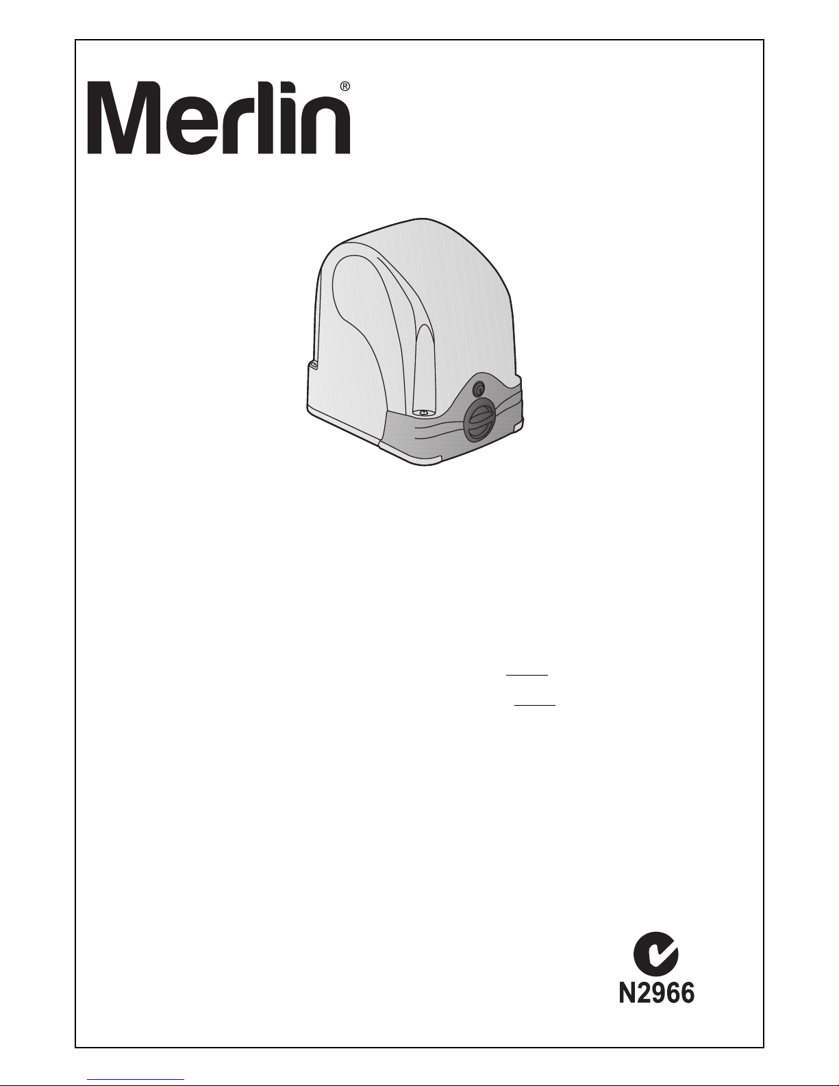
XLR8
MGS524
24 Volt DC
SLIDING GATE OPENER
INSTALLATION MANUAL
For Professional Installation ONLY
For level gradient installations ONLY
Chamberlain Australia Pty Ltd
PO Box 1446
Lane Cove NSW 1595
Phone toll free: 1800 638 234
Chamberlain New Zealand Ltd
PO Box 100-221
North Shore 0745
Phone toll free: 0800 653 667
www.go-merlin.com
Page 2
2
PLEASE START BY READING THESE IMPORTANT SAFETY RULES
This safety alert symbol means "Caution" - failure to comply with such an instruction involves risk of personal
injury or damage to property. Please read these warnings carefully.
This gate drive mechanism is designed and tested to offer appropriately safe service provided it is installed and
operated in strict accordance with the following safety rules.
Incorrect installation and/or failure to comply with the following instructions may result in serious personal
injury or property damage.
I
nstallation and wiring must be in compliance
with your local building and electrical
installation codes. Power cables must only be
connected to a properly earthed supply.
Disconnect electric power to the system before
making repairs or removing covers.
A disconnecting device must be provided in the
permanently-wired installation to guarantee allpole disconnection by means of a switch (at least
3mm contact gap) or by a separate fuse.
When using tools and small parts to install or
c
arry out repair work on a gate exercise caution
and do not wear rings, watches or loose
clothing.
Make sure that people who install, maintain or
operate the gate drive and/or the control board
are qualified and follow these instructions.
Keep these instructions in a safe place so that
you can refer to them quickly when you need to.
Please remove any locks fitted to the gate in order
to prevent damage to the gate.
Frequently examine the installation for imbalance
and signs of wear or damage to cables, hardware
and mountings. Do not use if repair or
adjustment is necessary. Gates which stick or
jam must be repaired immediately. Employ a
qualified technician to repair the gate, never
attempt to repair it yourself.
Keep additional accessories away from children.
Do not allow children to play with pushbuttons
or remote controls. A gate can cause serious
injuries as it closes.
After the installation a final test of the full
function of the system and the full function of
the safety devices must be done.
The full protection against potential squeeze or
entrapment must work direct when the drive arms
are installed.
This drive cannot be used with a gate
incorporating a wicket door unless the drive
cannot be operated with the wicket door open.
IMPORTANT FITTING AND OPERATING INSTRUCTIONS
W
ARNING / ATTENTION
Lightweight gates must be substantially
reinforced to avoid gate damage. The best
solution is to check with your gate manufacturer
for an opener installation reinforcement kit.
Gate must not extend over public byway during
operation.
Activate opener only when the gate is in full
view, free of obstructions.
Do not allow children to play near the gate.
This appliance is not intended for use by
persons (including children) with reduced
physical sensory or mental capabilities, or lack
of experience and knowledge, unless they have
been given supervision or instruction
concerning use of the appliance by a person
responsible for their safety.
Children should be supervised to ensure that
they do not play with the appliance.
PLEASE KEEP THESE INSTRUCTIONS
Entrapment protection devices MUST be
installed to protect anyone who may come
near a moving gate. Locate entrapment
protection devices to protect in BOTH the
open and close gate cycles. Locate
entrapment protection devices to protect
between moving gate and RIGID objects,
such as posts.
Controls must be far enough from the gate so
that the user is prevented from coming in
contact with the gate while operating the
controls.
Humidity and water destroy the control board.
Make sure under all circumstances that water,
humidity or dammed-up water cannot penetrate
the control board covering.
Automatic drive – Keep away from the area of the
gate since it may operate unexpectedly.
When opener is disengaged:
- gate must move freely when pushed by hand
- gate must not move on its own ie. no slope.
Do not install this opener on surfaces with a
gradient. Designed for flat surface installations
only.
Page 3
This sliding gate motor can be activated by hardware trigger inputs (keyswitches, keypads or induction
l
oops) as well as via the RF remote controls provided. The control board provides a variety of safety and
operating functions. Please familiarise yourself with these function to ensure the safest and most functional
automation of your gate.
A set of manual release keys is provided with your motor incase of power failure.
PLEASE LABEL THESE KEYS AND STORE IN A SAFE PLACE.
3
CONTENTS PAGE
SAFETY INSTRUCTIONS . . . . . . . .2
BEFORE YOU BEGIN . . . . . . . . . . .3
CARTON CONTENTS . . . . . . . . . . .3
INSTALLATION . . . . . . . . . . . . . .4-6
TYPICAL CONFIGURATION . . . . . .7
INSTALLATION OF CONTROL
BOARD . . . . . . . . . . . . . . . . . . . . . .7
WIRING OF CONTROL BOARD 8-10
ACCESSORIES . . . . . . . . . . . .11-12
JUMPER SETTINGS . . . . . . . . . . .13
INITIAL OPERATION/BASIC
SETTING . . . . . . . . . . . . . . . . . . . .14
PROGRAMMING THE TRAVEL
DISTANCE AND OPERATOR
FORCE . . . . . . . . . . . . . . . . . . . . .15
COMPLETION OF INSTALLATION/
PROGRAMMING . . . . . . . . . . . . . 16
SPARE PARTS . . . . . . . . . . . . . . .17
DIAGNOSIS LED . . . . . . . . . . . . . .18
FREQUENTLY ASKED
QUESTIONS . . . . . . . . . . . . . . . . .19
WARRANTY . . . . . . . . . . . . . . . . .20
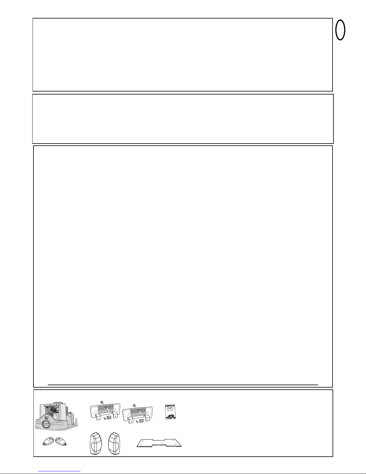
BEFORE YOU BEGIN
• Ensure the gate is in working order and suitable for automation.
Check that any wheels are in good working order, the track is free from obstruction and that the gate moves
smoothly throughout itʼs travel. If not, have the gate serviced by a gate installer.
• Ensure the motor you are installing is suitable for the gate weight and duty cycle.
Operating frequency / Duty cycle: MGS Sliding gate drives have a maximum duty cycle of approx. 30% (i.e. 30% per
hour) and not intended for commercial applications.
CAUTION: This device is not intended to run in high duty cycle applications, frequent activations may engage the units
thermal overload circuit. When this occurs the unit will cease operations until such time as the motor cools.
• Gate size: When calculating the gates weight allow for the gateʼs length, a light weight long gate (long = 5m or more)
needs far greater force to set it in motion than a short gate or heavy gate.
• Gate weight: Ensure that allowance is made not only for the gateʼs weight but its length and mobility.
Example: A light gate that slides poorly is likely to need a stronger drive than a heavy, smooth-sliding gate.
NOTE: Gate weight is only an approximate indicator, the actual relevance of which can vary greatly.
• Climatic conditions. Gate operating in high wind areas may be affected by side pressure on the gate. Timber or
metal lined gates may require additional force to operate in high winds. It is essential that this is allowed for before
installation.
• Temperature: Extreme low outdoor temperatures can make it difficult to operate the gate due to changes in the
ground conditions. A higher powered again might be necessary.
High outdoor temperatures can cause the thermal protection mechanism to be activated sooner.
• Safety: Your CB202 control board has outputs for flashing lamp as well as safety inputs for, contact strips, loop detectors
and photo electric safety beams (1 set of PE beams is provided). Please ensure that you comply with the standards and
regulations relevant to your particular installation.
• Control unit: The control unit was developed specifically with safety aspects in mind. It is located in the motor
housing.
0
4
1
S
L
G
-
1
2
5
S
A
located under the
motor cover.
• PE safety beams (1 set)
• Hardware bag
• Merlin C945 Mini remotes x 2
• Motor with housing
• PCB CB202 logic board
• Limit magnets (1&2) and
mounting accessories
• Base plate
MGS524 Carton contents
Page 4
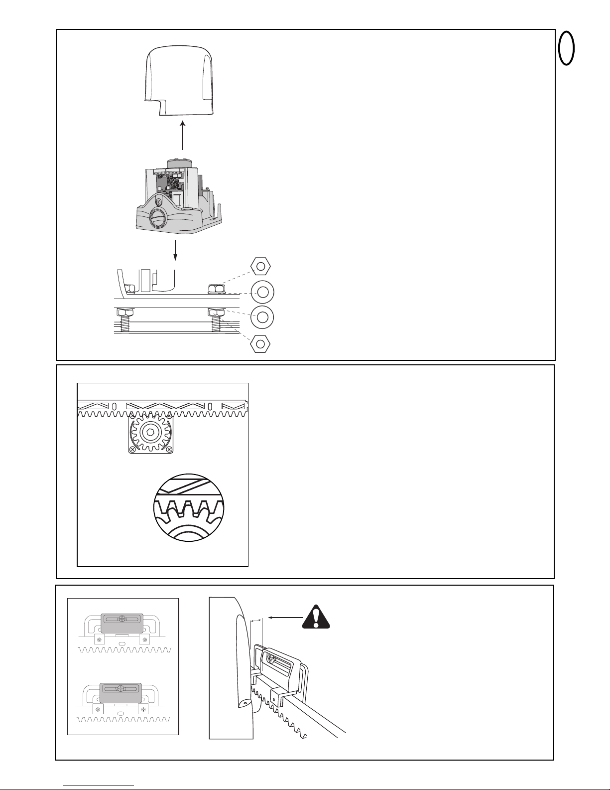
Positioning the motor and plinth.
B
efore preparing the plinth for use ensure that you have the correct
orientation and location for the motor.
No part of the motor or pinion should extend past the gate.
The motor plinth and all electronics should be located within the
propertyʼs boundaries.
The motor can be adjusted up and down and back and forth to some
degree however planning the location of your plinth and conduit exit will
save you time and effort.
Installing the base plate.
Where possible the base plate provided should be
installed into a concrete plinth.
The Base plate should be installed into a concrete plinth
of approximate 500mm x 500mm x 500mm for maximum
strength.
Ensure that a conduit is installed before adding the
concrete and that the exit point for the conduit is on the
correct side of the base plate in relation to the motor.
The plate has two recesses, ensure that the conduit
exits to the rear of the motor, this will facilitate the
passage of wire through the grommet located at the
base of the control box housing.
NOTE: For best results make sure the plinth
is level and has adequate drainage. Pooled
water around the base of the motor will
damage the gate motor.
200
215
1
2
40
60
28
30
270 mm
75 mm
160
160 mm
1
0
0
mm
180 mm
gate side
rear of motor
4
Installation
1.Turn key 180
2.Turn release mechanism 270
0
0
Manual release
In the case of a power failure or to move the gate freely
during installation the drive pinion must be disengaged.
To release the drive pinion.
• Turn the key 180 degrees to unlock
the release mechanism
• Turn the release mechanism 270
degrees to the right to release the
pinion.
NOTE: The gate should move freely once the drive
pinion has been released.
Page 5
5
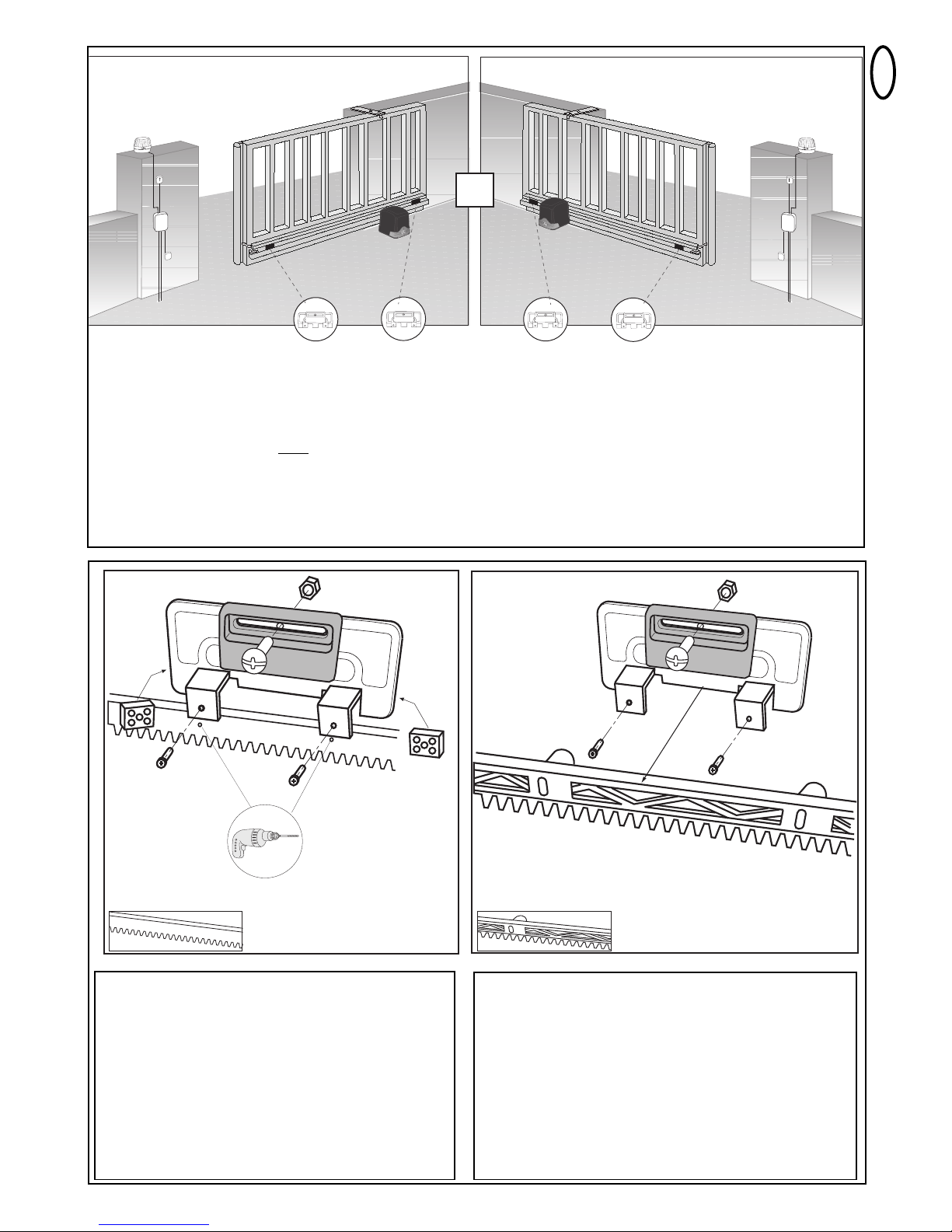
Mounting the Rack
To ensure the best gate travel the rack should follow the gates
movement. The rack should be fastened to the gate in section
follow the contours of the gateʼs travel. Release the gate drive as
detailed above first. Lay one section of rack across the drive
pinion parallel to the ground. Allowing for 1-2mm of clearance
between and the drive pinion and the rack to avoid pressure and
possible damage to the gears. Allowance should be made for
later adjusted to the rack, mark the first hole at the end of your
rack. Fasten the rack in place, role the gate forward and fasten
the remaining sections of rack using the same method.
Caution: You must have rack installed along the entire length
of its travel including the start and stop limits.
1-2mm clearance
between drive and rack.
M
ounting the Motor
Hand tighten one of the nuts provided onto each of
t
he four posts (tighten to about 15mm from the base
of the plate) then place a washer (provided) onto
each post.
Remove the cover from the motor and fit the motor
onto the threaded posts. Position the motor and
drive pinion approximately in place (some
adjustments may be required).
Place a washer onto each post then hand tighten
the nuts provided onto the post, some final
adjustments will be required so do not tighten the
nuts yet.
NOTE: Remove any foam packing from the motor
assembly.
Fitting the Magnets
Your MGS gate kit contains two magnets,
marked one and two. These indicate to the
gate motor the gate position it is essential that
they are fitted correctly and securely.
Magnets must be installed between
10-15mm from the limit switch
(see page 6).
A (1)
B (2)
max. 15mm
B (2)
A (1)
B (2)
Page 6
6
320001 (1 x 1m)
202097 (4 x 1m)
320003 (2 x 1m)
1
2
1
2
OR
Installing the magnet bracket steel rack.
Identify your start and stop limit. Using the magnet
bracket mark two holes as shown above. Drill two
holes into the rack then install the spacers provided
into the back tabs using the raised pins to position.
Once the spacers are in place, fit the bracket over
the rack and tighten the screws. Install the start and
stop limit magnets as outlined above using the bolt
and nylex nut provided.
Installing the magnet and bracket for nylon
rack.
Identify your start and stop limit. Fit the bracket over the
rack and tighten the screws. Install the start and stop
magnets as outlined above using the bolt and nylex nut
provided.
Installing the Limit Magnets
Caution: The magnet limit switches are polarity sensitive and can be installed in either of the positions as
marked above.
NOTE: Motor Wiring does NOT need to be reversed for left and right hand opening.
Caution: You must have rack installed along the entire length of its travel including the start and stop limits.
HEAVY DUTY STEEL RACK
PVC NYLON RACK
Page 7

7
TYPICAL CONFIGURATION OF A
SLIDING GATE UNIT
1. Drive with control board
The drive is located on a height-adjustable
mounting plate.
2. Photocell min. 150- max200 mm (optional)
First photocell.
Detects low objects.
3. Photocell max. 700 mm (optional)
Second photocell.
Detects vehicles and higher objects.
4. Flashing light (optional)
Important visual information indicating gate
movement.
5. Safety edge (optional)
Detects obstacles and avoids risks
produced by gate movement.
Safety edges can be mounted on the gate
or on the pillars. If the gate has openings
exceeding 45mm, a safety edge is
required on the pillar (accessory).
If required, safety edges must be mounted
at a height of up to 2.5m.
1
2
3
4
5
2
3
INSTALLATION OF CONTROL BOARD
The CB202 control board was designed for installation in a special
covering under the housing of the sliding gate drive.
The installation of the electrical controller is allowed only after the
completion of the mechanical installation. All work on the controller
must be performed after disconnecting it from the mains power supply.
Turn on the power only when it is prompted in the section INITIAL
OPERATION/ BASIC SETTING.
To operate, at least the following connections have to be established: -
- “Power supply”
- Transformer “Input & Transf”
- Motor “MOTOR”
- Plug limit switch “LIMIT SWITCH”
- Plug "RPM/ENCODER"
If necessary assemble the following optional connections:
- photocells
- safety edge
- flashing light
- external antenna
- key switch or other external control devices
NOTE: Plastic housing may need to be
loosened to tighten the Power Cable
Gland.
Page 8

8
W
IRING OF CONTROL BOARD
The cables for the power supply and the connected equipment can
be routed from below into the sliding gate operator through the
rubber seal at the bottom of the control box.
The controller is to be mounted with the terminal strips down as
shown in the picture.
The usage of shielded cable in order to connect the motor to control
board is highly recommended. Magnetic and inductive influence of
the signal in the cables can produce electric noise and may disturb
the function of the gate .
Generally avoid:
- 230 V and low voltage in the same power line. Not allowed by
electrical rules.
- Wiring of the photocells, switches, flashing lamps require a cable
separately from the motor wiring.
- Other wirings like telephone intercoms, lights for garden etc. must
be in separate cables.
- Rigid copper cables especially when thicker diameters are difficult
to manage during the installation and may result in bad
connections with functional issues. Use flexible cables instead.
- Cable material not suitable for outside use. Use cables suitable for
outside use and underground. Run the cables in conduits if the
cable is not suitable for placing in the ground (armoured or suitably
protected). Consult a local electrician if required.
General wiring sizes:
The numbers mentioned in the table below are minimum
requirements. It is always possible to use larger diameters.
- 230 V Supply Power to controller: min. 0,75mm² 3-pole
- Switches, infrared sensors, flashing lamp: See table etc.
min. 0.5mm²
Terminals:
The terminal blocks on the controller can be removed (pull) to
facilitate a convenient wiring and are pushed back only while
installing the controller. Even if a terminal strip is not in use, it must
be pushed back. The wiring is done as described in the wiring
diagram.
Plugs (available on the motor):
These plugs must be connected to the controller (plugged in).
The cable of the connectors are not routed from below, but from the
back of the controller (see picture).
1. 230 V transformer feeder TRANSF IN - connect to terminal
2. Limit switch
3. Motor connector RPM/Encoder - remove the extender cable from
RPM lead to enable connection.
4. Connect Green earth lead to Power lead.
Radio
The radio system is supplied as a small radio PCB module separate
to the main controller and plugged in when needed as shown in the
wiring diagram. A short cable antenna is always pre-assembled at
the factory.
NOTE: Transmitter will not work if the module is not plugged in.
Operator Model
External antenna
(Remove original
antenna of logic board)
Switches, Flashing lamp
etc.
Infrared Sensors
Distance
0m - 6m
Coax cable (Satellite
cable)
50 or 75 Ohm
0,5mm²
0,5mm²
Distance
6m - 10m
Coax cable (Satellite
cable)
50 or 75 Ohm
0,5mm²
0,5mm²
Distance
10m - 12m
Coax cable (Satellite
cable)
50 or 75 Ohm
0,75mm²
0,75mm²
Distance
12m – xx
Coax cable (Satellite cable)
50 or 75 Ohm
(max. 25m)
Min. 0,75mm²
Max. 30m
Min. 0,75mm²
Max. 20m
Blue
240VAC
Grey
(low voltage)
1
2
3
NOTE: MGS524 is factory terminated (ie. power cord is wired into
CB202 controller).
Consult a qualified electrician if your product requires alternative
iinstallation.
WIRE SIZES:
NOTE: The terminals are designed for a Max. cable diameter of 1.5m2(flexible wire).
Page 9

9
230V~
+/- 10%
50Hz
Model
CM475
(enclosure
required)
Ω
8.2
+
+
+
+
+
+
opening beam
closing beam
closing beam
closing beam
PHO1
PHO2
Radio
4
33MHz
Jumper OFF
Jumper ON
BLBL
Grey
WIRING DIAGRAM
TECHNICAL DATA OF CONTROL BOARD
Voltage: 230 V~ ±10% 50 Hz
Transformer: 230 V / 24 V, 105 VA
Output Motor: 24 VDC
Consumption max.: max. 400 W (in operation)
Consumption Standby: max. 4 W (without accessories)
Operating temperature: -20º C ÷ 55º C
Modes: Standard, Automatic
Measurements: 145 x 110 mm (without box)
Protection class Box: IP45
Fuse: 2 x 2 A (slow blow fuse)
Remote control: max. 180 x Rolling Code
feasible frequencies: 433 MHz
The motor control unit is a highly modern electronic unit controlled by
a microprocessor. It has all wiring facilities and functions required for
safe operation. The electronics can be used for the precise
adjustment of the push-pull torque. The gate can be held by hand if
the fitting/setting is correct. During operation, the gate can be
stopped at all times via remote control, push-button or key-operated
switch. The gate wing requires a firm stop for the “OPEN” and
“CLOSED” positions.
Humidity and water will destroy the control board. Make sure under
all circumstances that water, humidity or dammed-up water cannot
penetrate the control board. All openings and cable entries must be
sealed watertight.
Page 10

10
DESCRIPTION OF LED´S (LIGHT EMITTING DIODE)
DESCRIPTION COLOUR STATUS
STOP / 8.2 kOhms green Stop Switch
ON: Stop Active
OFF: OK
(Requires wire bridge if no
switch is connected)
EDGE green Safety Edge 8.2KOhm
ON: Activated
OFF: OK
(Requires 8.2KOhm resistor if not used)
“Key symbol” red Key-switch 2-wing opening
ON: Activated
OFF: OK
PHO 1 red Photocell 1 (close)
ON: OK, photocell connected
OFF: No photocell connected
PHO 2 red Photocell 2 (adjustable)
ON: OK, photocell connected
OFF: No photocell connected
OPEN LIM yellow limit switch GATE OPEN
CLOSE LIM yellow limit switch GATE CLOSED
LEARN yellow Programming indicator
ON: (flashing) programming is active
OFF: off
DGN red Diagnostic, also refer to page 18
CH1 red Remote control programming for
complete opening
ON: New remote can be
programmed
OFF: off
CH2 red Remote control programming for
partial opening (Refer to CH1)
DESCRIPTION OF TERMINALS
Description Function
230 VAC
50 Hz
POWER SUPPLY connector
TRANSF IN 230 V to transformer
INPUT 24 V 24 V from transformer
30VDC output 30 VDC battery kit terminal
for CM475 + enclosure
Motor blue cable
Motor red cable
24 V / 150 mA flashing light (accessory)
Key symbol keyswitch
COM negative pole
PHOTO2 photocells 2 (accessory)
PHOTO1 photocells 1 (accessory)
COM negative pole
STOP stop switch or
8.2 kOhms safety edge with 8.2 KOhms
(accessory)
RPM / ENCODER socket for rpm-sensor
LIMIT SWITCH socket for limit switch
RADIO MODULE SCKT socket for radio PCB module
ANT terminal for antenna
2A 2x slow blow fuse included 250V/2A
DESCRIPTION OF PUSH BUTTONS P1, P2, & P3
Button Function
P1+P2+P3 Limit setting: Push P1+P2+P3 simultaneously. The LED LEARN starts to flash as long as feature is activated.
P1 Button P1 operates Motor. Deactivate: Wait for 20 seconds or disconnect logic board from power.
P1 Force / travel distance - setting “BASIC DEFAULT”; from position CLOSE LIM
P1 + P2 Force / travel distance - setting “INSTALLER FORCE SETUP”; from position CLOSE LIM; with optional Soft-Stop setting
P2 ; P3 Timer to close. Factory setting: off. When the photocell beam is interrupted, the gate closes immediately without delay.
Refer to Timer to Close section (page 16).
P3 Software-reset to factory defaults. Push & hold for 10 seconds. Does not reset memory (see section “radio”).
Radio jumper + P1 Programming Remote for Channel 1
Command for OPEN completely
Radio jumper + P2 Programming Remote for Channel 2
Command for OPEN partially
Page 11

11
A
CCESSORIES (also refer to wiring diagram)
STOP SWITCH (OPTIONAL) MODEL: 600084
A stop switch to stop the movement of the gate in any direction can be connected to this output.
Also see STOP/8.2kOHM under “Jumper Settings”.
FLASHING LAMP (OPTIONAL) MODEL: FLA24-2
A flashing lamp can be connected to the control board. It warns when the gate is being moved. The flashing light should be fitted as high as
possible and in good clear view. The control board emits a constant signal that the lamp converts to a flashing signal.
Cable cross-section: 0.5 mm2or more.
Voltage: 24 V DC
KEY SWITCH (OPTIONAL) MODEL: 100010, 100027, 100034, 100041
The system can be operated by key switch (connectors: key symbol and COM). Also see OPEN/PED under “Jumper Settings”.
BACKUP BATTERY (OPTIONAL) MODEL: CM475 (24V/DC)
The terminals serve to reload an externally installed storage battery.
The integrated recharger is loaded and in case of power failure the battery provides power. A new fully charged storage battery may provide
power for more than 24 hours. Storage batteries are subject to deterioration and lose capacity. Due to extensive use they lose capacity even
faster. Replace storage batteries after approx. 2-3 years. CM475 is not for outside use and requires a suitable enclosure.
SAFETY EDGE (OPTIONAL) MODEL: 600046, 600053, 600077, 600060
A safety edge working according to the 8.2 kilo ohm principle can be connected to the control board, i.e. a 8.2 kilo ohm test resistor is attached
to the end of the safety edge. It ensures that the electric circuit is monitored permanently. The control board is supplied with an 8.2 kilo ohm
resistor installed. Several safety edges are connected in series. Cable cross-section: 0.5 mm
2
or more.
Also see STOP/8.2kOHM under “Jumper Settings”.
ANTENNA (OPTIONAL) MODEL: ANT4X-1LM
The control board is supplied with a wire antenna as standard. An external antenna (accessory) can be connected to terminals as shown.
A larger range (radio) can thus be achieved. For best range results mount antenna as high as possible.
PHOTOCELLS (INCLUDED) MODEL: 772ANZ
The photocells are for safeguarding the gate and must be used.
The fitting location depends on the gate’s design. EN12453
specifies that a pair of photocells must be installed at a height of
200 mm and activated to “Close”. The photocells consist of a
transmitter and a receiver and must be opposite each other. The
photocell is mounted on the wall using small screws and wall plugs.
To enable the “Automatic Closing” function, the Chamberlain failsafe
photocell must be installed.
Programming of IR sensors:
- connect IR sensors
- program the travel of the gate
- special feature: Fast closing gate
(see “Description of the Push Buttons P1, P2 & P3”)
Deletion of IR sensors:
Disconnecting already connected IR sensors will cause the control
board to block the functionality of the terminals it was connected to.
To delete IR sensors correctly:
- disconnect IR sensors
- cut control board from current shortly
- program the travel of the gate.
Diagnosis of the photocell
LED constant = OK
LED flashes = photocell disables control board
LED off = no current, incorrect connection or polarity
Diagnosis on the control board
LED constant = OK
LED off = OK no photocell connected
LED flashes = photocell disables control board
Connection between 1 & COM:
Active when gate is closing (reverses gate to open)
Connection between 2 & COM:
adjustable:
Jumper “PHO 2 MODE” unplugged >> active when gate is closing
Jumper “PHO 2 MODE” plugged >> active when gate is opening
230V~
+/- 10%
50Hz
Model
CM475
(enclosure
required)
Ω
8.2
+
+
+
+
+
+
opening beam
closing beam
closing beam
closing beam
PHO1
PHO2
Radio
433MHz
Jumper OFF
Jumper ON
BLBL
Grey
Page 12

12
Radio
433MHz
LOOP DETECTOR (OPTIONAL)
Jumper OPEN/PED must be plugged
Loop detectors react to metal and the most common use is for cars
or trucks but not for bikes or pedestrians.
Exit loop / Gate Opening Loop
An exit loop is behind the gate and opens the gate when closed,
keeps it open or re-opens the gate.
The jumpers OPEN/PED must be PLUGGED (in place).
The gate requires installed photocells and timer to close activated.
In addition, the feature “Fast closing” can be activated.
Refer to section “Description of Push Buttons P1, P2 & P3”
BRN GRN WHT YEL
SECOND
C
OM
P
HOTO
3 2 1
C
OM
E
DGE
8.2KΩ
STOP
PH
O
1
PH
O
2
P
ED
E
DGE
C
H1
CH2
1/2 MOTOR
P1
P2
P3
OPEN/STEP
LIGHT/SPY
OBSTACLE
SPEED 1
SPEED 2
RADIO
PHO 3
L
EARN
DGN
L
IGHT
CONTACT
PED
COM
STOP
NO
Model
203292
OPEN/PED
Jumper ON
RADIO AND RADIO PROGRAMMING
Insert radio module on designated pins, if not pre-installed.
PROGRAM / DELETE REMOTE CONTROLS
The receiver has two channels CH1 and CH2.
The respective LEDs CH1 and CH2 are assigned to these two channels.
Receiving a signal from a programmed remote control button, CH1 fully
opens the gate.
Receiving a signal from another programmed remote control button,
CH2 partially opens the gate (pedestrian mode).
PROGRAMMING
1. Insert (connect) jumper “RADIO”
2. Briefly push button P1 (for CH1) or P2 (for CH2) and the respective
LED lights up.
3. Press and hold a selected button on your remote control until LED
goes out after short flashing. Done!
Repeat for all remote controls (a maximum of 180 remote controls
can be programmed to each channel).
Important: To finish programming, remove (disconnect) jumper “Radio”!
Note: Make sure NOT to program the same remote control button to
CH1 and CH2, otherwise the gate will NOT work properly.
DELETE
1. Insert (connect) Jumper “Radio”.
2. Press and hold buttons P1 (for CH1) or P2 (for CH2) until the
respective LED goes out again (approx. 10 seconds).
Single remote controls can not be deleted. All remotes programmed
to this channel are deleted.
Important: To finish deleting, remove (disconnect) jumper “Radio”
Page 13

13
RADIO
The radio jumper is required to program remote controls.
For programming procedure please refer to page 12, section “radio”
FREE: No programming of remote controls possible
PLUGGED: Programming of remote controls possible
Important: Keep jumper “RADIO” disconnected
(removed) if not in use!
STOP/8,2 KOhm
Defines whether the terminal STOP/8,2KOhm is used for an
emergency stop or a safety edge. With an emergency stop any
movement of the gate will be stopped. When used for a safety edge
the gate reverses for 1 second.
FREE: Factory setting is 8,2KOhm. Safety edge or
8.2kOhm resistor is required.
PLUGGED: Emergency stop required. In this case the
resistor must be removed and replaced by the
switch or a switch circuit.
OPEN/PED
Defines if a key switch opens the gate completely or partially.
FREE: opens partially (ca. 100 -150 cm)
PLUGGED: opens completely
Note: If the jumper OPEN/PED is plugged and timer to close is
activated as well, the functionality of the terminals “key symbol” and
“COM” changes. See section “Loop Detector” above.
PHO 2 MODE
Defines whether the second photocell is active in closing or in closing
& opening.
FREE: active in closing
PLUGGED: active in opening
OBSTACLE
Factory-equipped with fixed wire jumper. Cutting through increases the
operating power at the control.
CAUTION: If the jumper is severed, the gate system should be
secured with additional safety devices (contact strip, etc.).
Werkseitig mit fester Drahtbrücke ausgestattet. Durchtrennen erhöht
die Arbeitskraft an der Steuerung.
JUMPER SETTINGS
Page 14

14
BASIC SETTING (to identify magnet position):
1. Bring the gate manually to a position between the two
limit switches OPEN - CLOSE and lock drive.
2. Press buttons P1, P2 and P3 at the same time for about
2-3 sec. LED "LEARN" starts to flash.
3. Now watch the gate. The gate can be moved in both
directions using the button P1. Press the button P1
several times (1-2 seconds each time) to understand the
function of the button. If none of the buttons are pressed
for about 15 seconds, the control switches back to normal
operation. Repeat step 2 in this section.
4. Fully open the gate with the button P1.
Keep P1 pressed until the controller turns off by itself at
the limit switch OPEN. (Do not release beforehand).
Control: The LED "OPEN LIM" (yellow) = limit switch
OPEN should now light up and the gate can be opened
as required. Otherwise, change the limit switch position
before further settings are made.
5. Close the gate with the button P1 till it is turned off at the
limit switch CLOSED. (Do not release beforehand).
Control: The LED "CLOSE LIM" (yellow) = limit switch
CLOSED should now light up and the gate can be closed
as desired.
Basic setting is completed.
- Wait for “learn” to stop flashing
- Proceed to next step
2
.
2.
2
.
2.
2.
2
.
2.
2
.
2.
2.
INITIAL OPERATION / BASIC SETTING
Proceed step by step. When in doubt, start again at the beginning. Take sufficient time to make these settings.
1. Are all components required for operation connected? Motor, photocells, safety contact strip, stop switch.
2. Limit switches are fixed to the rack?
3. Setting of jumpers => all removed (settings can be done later on)
5. Make sure nobody is present in the gate area.
Now connect control board to power
Page 15

15
1. The gate is at the limit switch CLOSED.
2. Press P1 and P2 simultaneously for a longer time (about
5-6 seconds) until the gate opens.
Release buttons! LED “LEARN” flashes.
3. Press P1. Soft-stop in the OPENING direction starts from
this position.
4. Press P1 again when the gate moves in CLOSING
direction, soft-stop starts from this position.
When LED "LEARN" goes out, the programming is
completed successfully.
2.
2.
2.
2.
2.
2
.
2
.
2.
PROGRAMMIING THE TRAVEL DISTANCE AND OPERATOR FORCE
Below are two methods of configuring the opener ’s travel
1. Basic Default Setup - Slowest travel
2. Installer setup - Faster travel (optional soft start/soft stop)
1. BASIC DEFAULT FORCE SETTING
(Default speed - fast start then slows down)
1. The drive is at the limit switch CLOSED.
LED "CLOSE LIM" glows.
2. Press the button P1 until the gate starts to open.
(LED "LEARN" glows)
The automatic programme starts (slow speed).
3. The drive moves the gate to the limit switch OPEN,
stops briefly and then moves back to the limit switch CLOSED.
4. After reaching the limit switch CLOSED, the LED
"LEARN" goes out. The programming of the distance and
the force required is completed.
Proceed with “Radio and Radio Programming” and “Completion of Installation”.
2.
2.
2.
2.
2.
2.
2.
2.
2.
2.
2. INSTALLER FORCE SETUP
(Faster speed with optional soft stop function)
PROGRAMMING THE DISTANCE "ADVANCED" (INDIVIDUAL)
NOTE: The button P1 must be pressed firmly several times during this set up. Each press of the button will determine the position at which the softstop (slow rampdown speed) is activated. ie. The installer can set the soft stop function at any point of the travel.
Page 16

16
FORCE / TORQUE OF MOTOR
Thrust of the motor is set automatically while programming the travel
distance. Thrust can only be modified by programming the travel
distance again. If gate movement is impeded by weather or changes
to the installation (rust or inappropriate lubrication) it may have to be
repaired.
The control board complies with the latest EU guidelines.
One of these guidelines specifies that the closing forces
at the gate edge must not exceed 400N (40 kg) for the last 500 mm
before the gate is CLOSED. Above 500 mm, the maximum force at
the gate edge must not exceed 1400 N (140 kg). If this cannot be
ensured, a contact strip must be mounted on the gate at a height up
to 2.5 m or on the pillar on the opposite side (EN12453).
BATTERY DISPOSAL
Batteries and rechargeable batteries may not be disposed along with domestic waste, but are
obliged to be returned.
After use they can be returned free of charge locally e.g. in trade or at municipal collecting points.
Batteries and rechargeable batteries are marked with a crossed waste container as well as with the
chemical symbol which describes their toxic element, “Cd” for cadmium, “Hg” for mercury and “Pb”
for lead.
12VDC
Pb Cd Hg
COMPLETION OF INSTALLATION / PROGRAMMING
Once the travel distances are programmed, the remote controls can be programmed as well.
(Refer to “Radio and Radio Programming”)
1. You can now let the gate run 2 complete cycles by pressing a key on the remote or a connected switch and observe the
process. Close the gate again, WITHOUT making another setting.
2. Check operation of photocells, switch, flashing light, remotes, accessories, etc.
3. Advise people using the gate with regard to gate operation, safety functions and how to release the gate in order to operate it manually.
TIMER TO CLOSE (AUTO-CLOSE)
NOTE: Only possible with connected photocells. Time frames from 2 seconds up to 120 seconds are possible.
Activate:
1. Press and hold P2 until yellow LED starts flashing
2. Now count the time you wish to program
3. Press P2 again. Done!
Deactivate:
1. Press and hold P2 until yellow LED starts flashing.
2. Press P3. Yellow LED goes out. Done!
Page 17

17
P
CB Housing
0
41ASLG-1078
K
ey for Release
Mechanism
041ASLG-0054
Release Mechanism
041ASLG-0185SA
B
ase Housing
041ASLG-1150SA
L
imit Reader
0
41ASLG-0383SA
Gear Assembly
041ASLG-1004SA
Replacement Housing
0
41ASLG-0198
W
orm Gear
0
41ASLG-0310SA
Motor Assembly
0
41ASLG-0375SA
0
41ASLG-0353
MGS500
Transformer
041ASLG-0374
Magnets
041ASLG-0053M
L
ogic Board
C
B202
SPARE PARTS
Page 18

18
DIAGNOSIS LED
The LED diagnostics always shows the latest upcoming issue. If several issues are existing the LED diagnostics does not show them.
Example: The gates’ guiding rail is soiled and the drive performs a safety reversal due to too high force. After that the photocell beam got
interrupted. Diagnosis: As long as the photocell beam is interrupted the diagnosis LED flashes 6x respectively 7x.
Indication Description Remedy
1x blinking Motor has insufficient connection to control board Cables not wired or badly connected.
Check terminals precisely. Consider wire lengths
2x blinking Limit switch GATE CLOSED Progamming travel distance failed because the gate never
reached the limit switch GATE CLOSED. Repeat programming
the travel distance according to instructions
3x blinking Limit switch GATE OPEN Progamming travel distance failed because the gate never
reached the limit switch GATE OPEN. Repeat programming
the travel distance according to instructions
4x blinking Interruption of programming / no programming A: Button P1 was pressed too often during “programming travel
distance advanced”
B: The control board has never been programmed
5x blinking Force too high. Force very unsteady A: Gate to heavy or rough running
B: Gate blocked / or rough running at a certain position
C: Gate not balanced
D: Faulty mechanical installation
All: Consult gate dealer/specialist
6x blinking Photocells 1 block installation
A: Obstacle interrupts beam A: Remove obstacle
B: Poor alignment of the lenses B: Check alignment
C: Power supply for photocells not sufficient C: Check terminals and wire diameter
7x blinking Photocells 2 block installation refer to 6x blinking
8x blinking Emergency stop blocks installation A: Check wires and wiring
B: Check basic setting of control board (jumpers)
9x blinking Safety edge blocks installation
A: Obstacle pushes safety edge A: Remove obstacle
B: Safety edge defective B: Check wires, wiring and 8.2kOhm resistor
C: Power supply too low or wire damaged C: Check basic setting of control board (jumpers)
10x blinking Power supply to control board too low
A: 230V supply defective or faulty connection A: Check terminals/connections
B: Damaged wire in powercable B: Consult dealer/specialist
C: Back up battery (optional accessory) empty C: Charge battery min. 24h
11x blinking EEPROM Fault
Power up failed Replace contol board
12x blinking Defect on relay or major electrical component Replace logic board
A: Overload
B: Bad wiring (wrong)
D: Water in photocells (bad installation) Check wiring
E: A photocell was connected before Reprogram the travel distance from gate fully closed
but not removed (disconnected)
Page 19

19
The gate opener doesn’t respond at all; no LED is
on.
Possibly power failure.
1. Check conductor and zero conductor.
2. Check house fusing.
Check whether the radio module is
seated correctly.
Immediately after the gate has started moving, it
stops and reverses.
Obstacle in area of gate.
Gate rough running (consult dealer)
Check gate area for objects
Check photocells
Reprogram travel distance
Gate can only be opened
Photocell blocks Function and connection must be
checked
“Timer to close” doesn’t work.
Only works if the 2-cable photocell 770,771
or 772 installed.
The control board does not work any more using
the transmitter, only with the switch and even then
only as long as a button is pressed and kept
pressed.
Photocell, a contact strip or the emergency
stop disables the control board.
Only one photocell was connected for OPEN
At least 1 pair of photocells active in
OPEN or CLOSED must be connected
The gate opener doesn’t respond at all, although
the controller has been connected (LEDs are on).
1. Remote control not programmed.
2. LEDs indicate a fault.
3. Photocell connected incorrectly.
4. Motor terminal possibly not connected
properly.
1. Programming remote control.
2. Find and rectify fault(s) (see description of
diagnostic LEDs).
3. Check photocell connection / programming.
4. Check terminals and connections.
The remote control’s range is too short.
The installation of an external aerial is recommended as the controller with the short cable
aerial is located either behind the post or near ground level in most cases. The optimum
location of the aerial is as high as possible in all cases. An appropriate aerial with installation
kit can be obtained from Chamberlain as an accessory.
The gate must follow a slope.
Not recommended! Change gate! The gate can move in an uncontrolled (dangerous) manner if
the gate opener has been released. A stronger force is needed in the upwards direction of the
slope and then, in the opposite direction, the gate opener’s force is too strong.
FAQs
Pressing P1, P2 and P3 does not show any reaction
Jumper “RADIO” must be removed.
Check whether the radio module is
seated correctly.
Travel distance can’t be programmed. 1. Jumper setting not correct
2. See Diagnostic LED
3. Interferences in wiring of photocells, switch
or safety edge
4. Gate moves for 1 second only and stops
without reversal during programming
5. Magnetic limit switch
1: Follow the instructions of “initial operation”
closely
3: Remove for checking, then re-program
travel distance
4: Check RPM sensor/Encoder on control
board
5: Install magnetic limit switch properly
The operator sometimes moves slowly
Power failure Common procedure. After power failure the
operator performs a selftest. Depending on
the operator model this can take a few
seconds or a complete cycle. Do not interrupt
this test via remote control or switch,
otherwise the limits may change. If this is the
case reprogram travel distance using P1.
Control board does not work Travel distance not programmed Program travel distance. See initial
operation / diagnosis LED
Control board does not work with transmitter 1. Transmitter not programmed
2. Photocells block
3. Jumper “RADIO”
1.Program transmitter
2.Check photocells, check diagnostic LEDs
3. Jumper “RADIO” must be plugged.
Gate doesn’t open completely Gate heavy / rough running Re-program travel distance
Consult dealer/specialist
Limit switches OPEN and CLOSED not correctly
indicated
Incorrect programming
During programming the limit switch OPEN
must be reached using P1, then limit switch
CLOSED. Switching motor cables is not
required.
Gate opens instead of closing automatically
(timer to close activated)
Incorrect programming
Repeat programming as described in these
instructions
Page 20

20
5 problems caused by electrical faults or replacement of batteries;
6 water or moisture ingress that causes corrosion or electrical
malfunction;
7 corrosion caused by sea air if located near a waterway, beach etc;
8 fitment in a commercial operating application; or
9 solid panel gates installed in an unprotected wind affected location
resulting in the gate not closing;
10 gate travel encounters an incline/decline.
NB: A General Purpose Outlet (GPO) ie: power point must be
supplied by the consumer as this electrical fitting does not form a part
of the Unit (opener). Excludes solar installations.
If this Chamberlain Limited Warranty does not apply, you may have
rights available to you under the Australian Consumer Law.
Liability – Australia only
Except as set out in the Australian Consumer Law (being Schedule 2
of the Competition and Consumer Act 2010) (as amended,
consolidated or replaced):
1 all other guarantees, warranties and representations in relation to
the Unit or its supply are excluded to the extent that Chamberlain
can lawfully exclude them; and
2 under no circumstances will Chamberlain be liable for
consequential, incidental or special damages arising in connection
with the use, or inability to use, the Unit, other than those which
were reasonably foreseeable as liable to result from the failure.
Liability – New Zealand only
Except as set out in the Fair Trading Act 1986 and the Consumer
Guarantees Act 1993 (as amended, consolidated or replaced):
1 all other guarantees, warranties and representations in relation to
the Unit or its supply are excluded to the extent that
Chamberlain can lawfully exclude them; and
2 under no circumstances will Chamberlain be liable for
consequential, incidental or special damages arising in connection
with the use, or inability to use, the Unit, other than those which
were reasonably foreseeable as liable to result from the failure.
Note: We request that you retain your sales docket or invoice as
proof-of-purchase and attach it to this manual to enable you to
establish the date of purchase in the unlikely event of a warranty
service being required. Chamberlain reserves the right to
change the design and specifications of the Unit without prior
notification. Some features or accessories of the Unit may not be
available in certain markets or areas. Please check with your
distributor.
Chamberlain service centre contact details
Australia
Phone toll free 1800 638 234
Fax toll free 1800 888 121
Chamberlain Australia Pty. Ltd.
PO BOX 1446
Lane Cove NSW 1595
New Zealand
Auckland phone 09 477 2823
Phone toll free 0800 653 667
Fax toll free 0800 653 663
Chamberlain New Zealand Ltd
PO BOX 100221
North Shore 0745
Email: customerservice@chamberlainanz.com
Website: www.go-merlin.com
709269-2-C © 2012 Chamberlain Group, Inc
CHAMBERLAIN LIMITED WARRANTY
Merlin Professional MGS524
Sliding Gate Opener
Chamberlain Australia Pty Limited / Chamberlain New Zealand Limited
(Chamberlain), the manufacturer of Merlin® automatic gate openers, is
committed to manufacturing and supplying high quality goods.
As part of this commitment, we seek to provide reliable service and
support for our goods and are pleased to provide you, the original
purchaser, with this Chamberlain Limited Warranty.
We also provide the following statement as required by the Australian
Consumer Law: In Australia, in addition to your rights under this
Chamberlain Limited Warranty, our goods come with guarantees that
cannot be excluded under the Australian Consumer Law. You are
entitled to a replacement or refund for a major failure and for
compensation for any other reasonably foreseeable loss or damage.
You are also entitled to have the goods repaired or replaced if the
goods fail to be of acceptable quality and the failure does not amount
to a major failure.
Chamberlain’s warranty
Chamberlain warrants to the original purchaser of the Merlin® Sliding
Gate Opener (Unit) that all parts of the Unit, other than remote
controlled transmitters and accessories, globes and batteries, are free
from defects in materials and workmanship for a period of 24 months
from the date of purchase when installed in a residential premise with a
residential specified gate that is designed for the sole purpose of
domestic domicile. Chamberlain warrants that remote controlled
transmitters and accessories included with the Unit are free from
defects in materials and workmanship for a period of 12 months from
the date of purchase.
Batteries and globes are not covered under the Chamberlain Limited
Warranty.
It is a condition of this Chamberlain Limited Warranty that the Unit is
sold, installed and serviced by a Professional Dealer appointed by
Chamberlain. A Merlin® branded gate opener purchased over the
internet and installed by a person other than a Professional Dealer will
not be covered by this Chamberlain Limited Warranty.
During the applicable Chamberlain Limited Warranty period, if you are
concerned that the Unit may be defective, for prompt on-site service call
the Professional Dealer that sold/installed the opener, or our service
centre on the toll free number below and a Chamberlain technician will
diagnose the problem and arrange for this to be rectified. Once the
problem has been diagnosed, subject to your rights under the
Australian Consumer Law with respect to major failures, Chamberlain or
its Professional Dealer will provide you with:
1. repairs to the Unit
or
2. a replacement Unit.
Repairs and replacement parts provided under this Chamberlain
Limited Warranty are provided free of charge and are warranted for the
remaining portion of the original warranty period.
This Chamberlain Limited Warranty provides benefits which are in
addition to your other rights and remedies as a consumer.
Exclusions
If our service centre determines that a warranty claim has been made in
respect of a failure or defect arising under or out of any exclusion
detailed below such that the claim is not covered under this
Chamberlain Limited Warranty, we may, subject to your other rights and
remedies as a consumer, charge you a fee to repair, replace and/or
return the Unit to you. This Chamberlain Limited Warranty does not
cover any failure of, or defect in, the Unit due to:
1 non-compliance with the instructions regarding installation,
operation, maintenance and testing of the Unit or of any product
with which the Unit is used;
2 any attempt by a person other than a Professional Dealer to repair,
dismantle, reinstall or move the Unit to another location once it has
been installed;
3 tampering, neglect, abuse, wear and tear, accident, electrical storm,
excessive use or conditions other than normal domestic use;
4 problems with, or relating to, the gate or gate hardware, including
but not limited to the gate;
TM
Trademark of The Chamberlain Group, Inc.
® Registered Trademark of The Chamberlain Group, Inc.
 Loading...