

Merlin WeatherDrive MR550EVO Installation Manual
Rolling Garage Door Opener
Installation and Operating Instructions
Owners Copy: Please keep these instructions for future reference
This manual contains IMPORTANT SAFETY information
DO NOT PROCEED WITH THE INSTALLATION BEFORE READING THOROUGHLY
gomerlin.com.au
gomerlin.co.nz
MR550EVO

1
IMPORTANT
* The use of the Key Lockable Release is for use in Commercial
Applications ONLY, and not to be used when installed in a Residential
Application (refer safety standard AS/NZS 60335.2.95). An alternative exit
path from the building MUST BE AVAILABLE when using the Key Lockable
Feature.
* This Merlin Unit is rated to IP34 and has a UV stabilizer added, however, to
ensure the best operation of the opener the installer should ensure that it
is protected from the elements. It should not be exposed to driving water
or rain, or extended periods of direct sunlight. It must not be immersed in
water or sprayed directly by a garden hose or pressure cleaner.
2
(live or moving)
indicateshazardousparts
T
he "ash" symbol
1000mmMIN
150mmMIN
indicatedby the IP code.
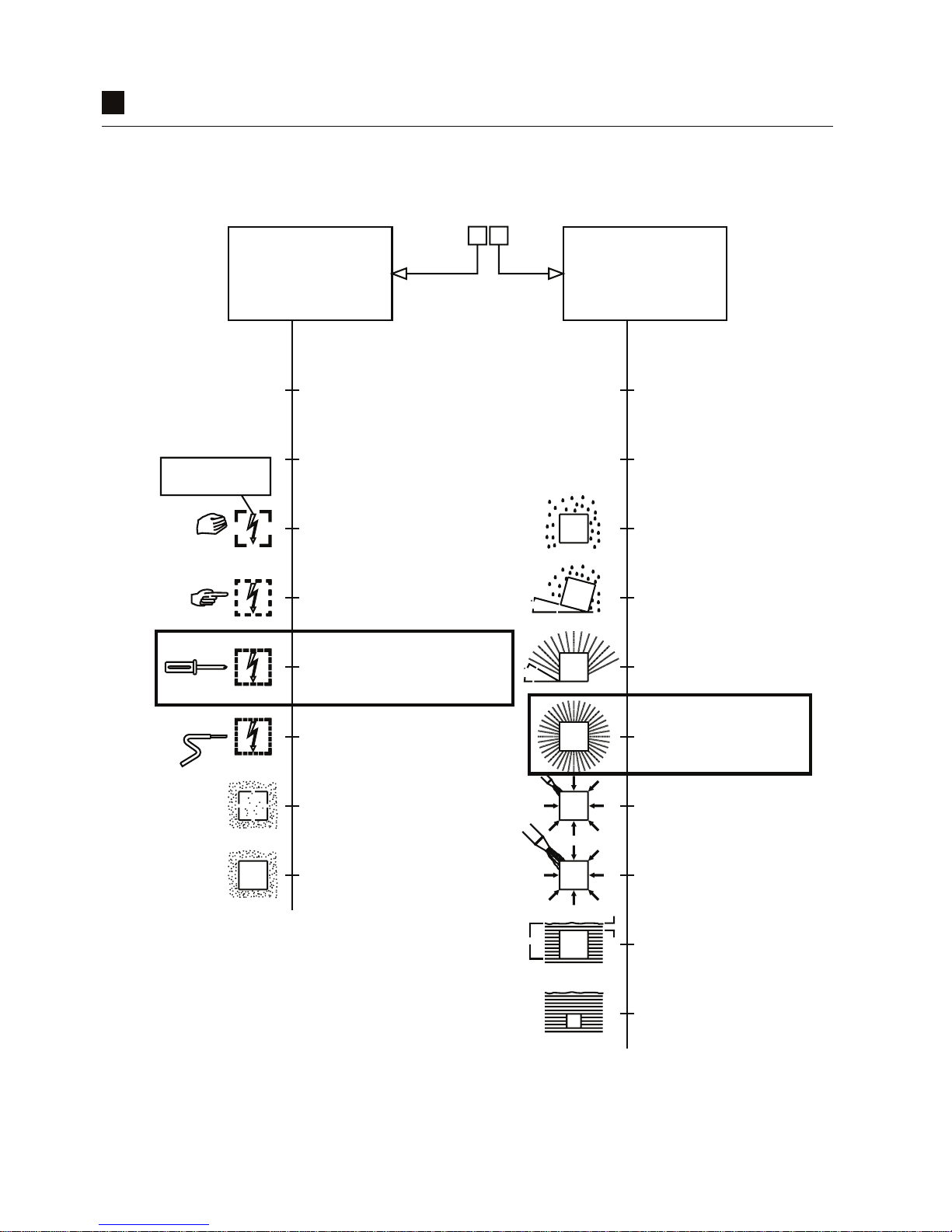
Protection of persons and protection of equipment
by the IP codes two:
for electrical equipment is indicated
Protection provided by enclosures
objects.(see AS 1939, Clause 5)
againstingress of solid foreign
and protection of equipment
accessto hazardous parts,
protectionof persons against
The rst numeral indicates
(see AS 1939, Clause 6)
harmful ingress of water.
protection of equipment against
The second numeral indicates
X
0
1
2
3
4
5
6
X
1
2
3
4
5
6
7
8
0
(untested)
Protection unspecied
(untested)
Protection unspecied
Non-protected Non-protected
falling vertically.
Protection against drops of water
position (in any direction)
is tilted up to 15 from its normal
falling vertically when the object
Protection against drops of water
at up to 60 from the vertical.
Protection against spraying water
directions.
spraying water from all practicable
Protection against splashing and
directions.
jets of water from all practicable
Protection against low pressure
practicable directions.
strongjet of water from all
Protection against heavy seas or a
immersion.
Protection against temporary
thansecond numeral 7)
agreement,but no less severe
submersion (tests subject to
Protection against continous
than 50mm.
of equipment against objects larger
hazardous parts, and protection
againstaccidental access to
Protection of the back of the hand
than 12.5mm.
equipmentagainst objects larger than
to hazardous parts, and protection of
Protection of ngers against access
objects larger than 2.5mm (e.g. ball bearings)
and protection of equipment against
or wires (larger than 2.5mm diameter),
Protection of persons holding tools
objects larger than 1mm. (e.g. ball bearings)
and protection of equipment against
tools or wires (larger than 1mm diameter),
Protection of persons holding small
satisfactoryoperation of equipment.
sucient quantity to interfere with
Protection against entry of dust in
entry of dust.
Completeprotection against
CHARACTERISTIC NUMERALS
IP
1
5
3
0
IP RatingChart
3
CONTENTS PAGE
SAFETY INSTRUCTIONS . . . . . . 3
CARTON INVENTORY . . . . . . . . . .4
TOOLS REQUIRED . . . . . . . . . . . .4
DOOR REQUIREMENTS . . . . . . . .4
PREPARE & TEST THE DOOR . . .5
CONTROL PANEL . . . . . . . . . . . . . .6
MANUAL RELEASE KEY
LOCKABLE . . . . . . . . . . . . . . . . . . .7
PINNING THE DOOR . . . . . . . . . . .8
INSTALLATION PROCEDURE . . . .9
ADJUSTMENT & TESTING . . .10-11
INSTALL THE PROTECTOR
SYSTEM . . . . . . . . . . . . . . . . . . . .12
INSTALLING WIRELESS WALL
BUTTON . . . . . . . . . . . . . . . . . . . .13
TRAVEL SPEED . . . . . . . . . . . . . .13
STANDBY MODE . . . . . . . . . . . . .14
AUDIBLE BEEP . . . . . . . . . . . . . . .14
CONTROL PANEL E-LOCK . . . . .15
PARTIAL OPENING . . . . . . . . . . .15
WIRELESS PROGRAMMING . . . .16
OPERATING YOUR OPENER . . .17
MAINTAINING YOUR OPENER . . 17
CARE OF YOUR OPENER . . . . . 17
SPECIFICATION . . . . . . . . . . . . . .17
ACCESSORIES & WIRING . . . . . .18
SPARE PARTS . . . . . . . . . . . . . . .19
TROUBLESHOOTING . . . . . . . . .20
DIAGNOSTIC CHART . . . . . . . . . .21
WARRANTY . . . . . . . . . . . . . . . . .22
T
he opener must not be used on a wicket
d
oor (door within a door).
The Protector System
TM
must be used for all
installations where the closing force as
measured on the bottom of the door is over
400 N (40 kgf). Excessive force will interfere
with the proper operation of the safety reverse
system or damage the garage door.
After installation, ensure that the parts of
the door do not extend over public
footpaths or roads.
Install the wireless wall control (or any
additional wall control) in a location where
the garage door is visible away from
moving parts, at a height of at least 1.5 m
and out of the reach of children. Do not
allow children to operate push button(s) or
transmitter(s). Serious personal injury from a
closing garage door may result from misuse of
the opener.
Permanently fasten the Warning Labels in
prominent places, adjacent to wall controls
and manual release mechanisms as a
reminder of safe operating procedures.
Activate opener only when the door is in
full view, free of obstructions and the
opener is properly adjusted. No one should
enter or leave the garage while the door is
in motion.
Do not allow children to play near the door,
or with door controls.
If the supply cord is damaged, it must be replaced
by the manufacturer, its service agent or similarly
qualified persons in order to avoid hazard.
Disconnect electric power to the garage
door opener before making repairs or
removing covers.
KEEP THESE INSTRUCTIONS
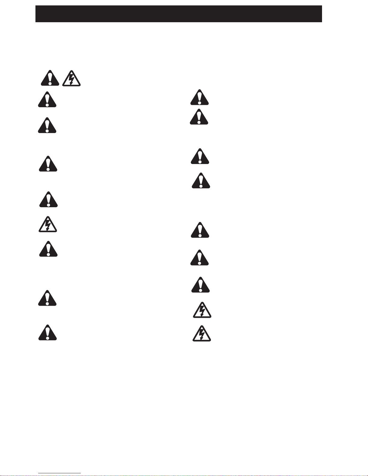
WARNING
•Failure tocomply withthe following instructionsmay resultinserious personalinjuryorpropertydamage.
•
Read and follow all instructions carefully.
• The garage door opener is designed and tested to offer safe service provided it is installed and
o
perated in strict accordance with the instructions in this manual.
These safety alert symbols mean WARNING : A possible risk to personal safety or
property damage exists.
NOTE: If your garage has no service entrance door, a CM1702 or DMK1 outside quick release must be installed.
This accessory allows manual operation of the garage door from outside in case of power failure.
Keep garage door balanced. Do not let the
garage door opener compensate for a binding or
sticking garage door. Sticking, binding or
unbalanced doors must be repaired before
installing this opener.
Do not wear rings, watches or loose clothing
while installing or servicing a garage door opener.
Wear gloves and suitable protective clothing
where appropriate.
Frequently examine the door installation, in
particular cable, springs and mountings for signs
of wear, damage or imbalance. Do not use if
repair or adjustment is needed since springs and
hardware are under extreme tension and a fault
can cause serious personal injury.
To avoid serious personal injury from
entanglement, remove all ropes, chains and
locks connected to the garage door before
installing the door opener.
Installation and wiring must be in compliance
with your local building and electrical codes.
The safety reverse system test is very
important. Your garage door MUST reverse on
contact with a 40 mm obstacle placed on the floor.
Failure to properly adjust the opener may result in
serious personal injury from a closing garage
door. Repeat the test once a month and make
any necessary adjustments.
This appliance is not intended for use by persons
(including children) with reduced physical, sensory
or mental capablities, or lack of experience and
knowledge, unless they have been given
supervision or instruction concerning use of the
appliance by a person responsible for their safety.
Automatic Drive - Keep away from the area of
the door as it may operate unexpectedly.
START BY READING THESE IMPORTANT SAFETY INSTRUCTIONS
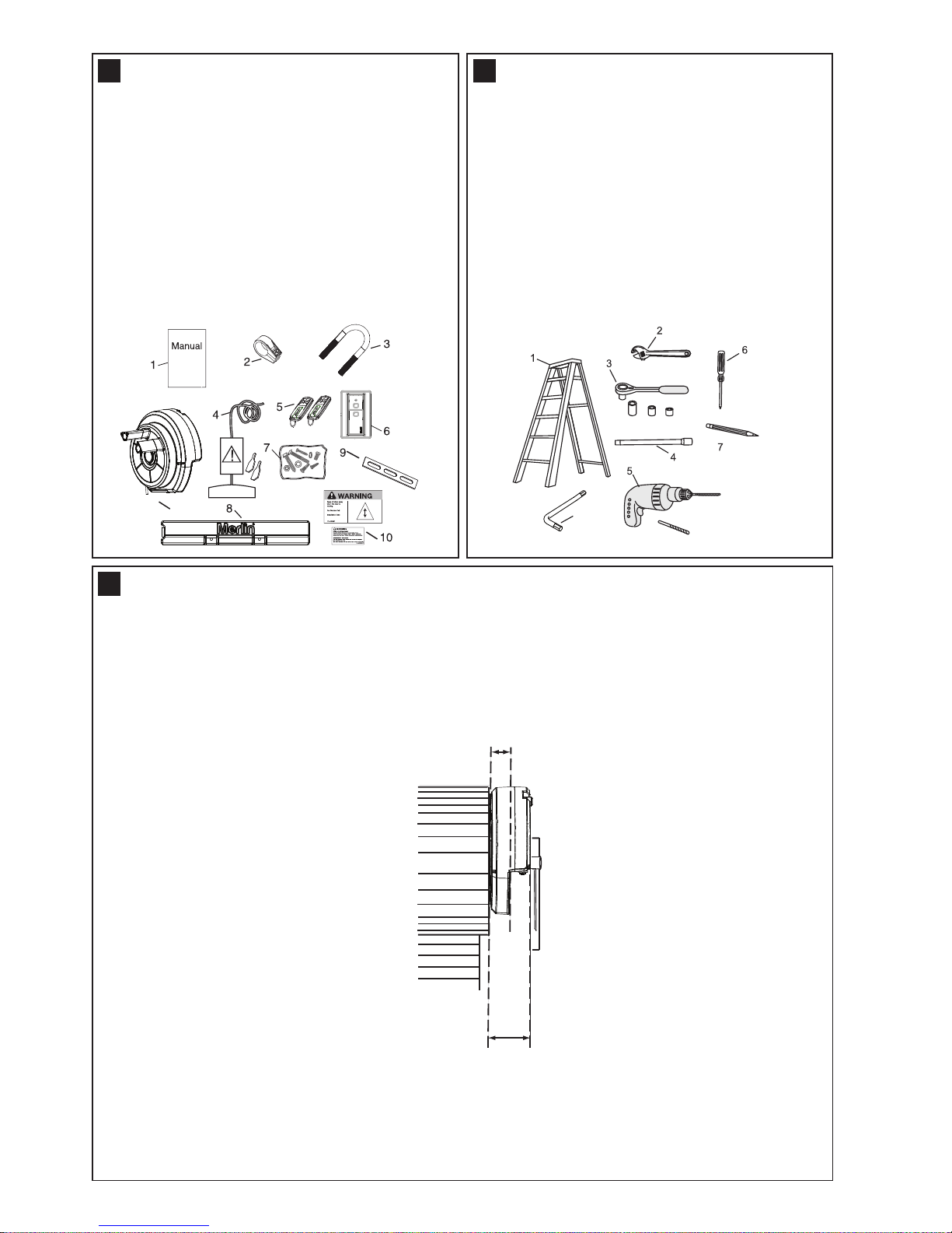
1. Instruction manual (this document)
2. Stop collar
3. Clamp bracket
4. Release handle, cord, keys and risk of entrapment
card
5. Premium+ transmitters (2)
6. Wireless wall button
7. Hardware bag
8. Weight bar
9. Clamp plate
10. Warning label and risk of entrapment label
11. Opener
C
ARTON INVENTORY
1
11
13 mm, 10 mm, 8 mm
5.5 mm
8
TOOLS REQUIRED
2
1. Ladder
2. Adjustable wrench for U-bolts already installed
on the door
3
. 8 mm socket, 10 mm socket and 13 mm extended
socket and socket wrench
4. 300 mm socket extension (for minimum side-room
installations)
5
. Drill and 5.5 mm drill bit
6. Philips-head screwdriver
7. Marker pen
8. 8 mm allen key
9. Door stand or similar device to safely support door
(not shown)
DOOR REQUIREMENTS
3
Ensure that there is at least 40 mm from the edge of the curtain to the edge of the bracket. If the roller door
drum is on the edge of the curtain or is a smaller diameter, additional clearance may be required.
95 mm
Minimum distance from
edge of curtain to edge of
door bracket 40 mm
Direct clamping
method
The maximum allowable door height is 5.5 m with a maximum curtain area of 15.0 m²* . The door must be spring
balanced.
*The Protector System™ (IR Beams) must be installed if the force at the edge of the closing door exceeds
400 N (40 kgf). Door axle diameter must not exceed 35 mm.
4
T
ESTING THE DOOR
4
Non opener side
Opener side
INSTALLING THE STOP COLLAR
5
• Place the weight in the centre of the door (as shown).
• Use a pencil to mark the two hole positions.
• If the door curtain does not have a handle you will need
to drill two 5.5 mm holes through the two marked
positions, then place the weight bar on the inside of the
door.
• Use the bolts, washers and nuts (provided) to
fasten the weight bar in place.
NOTE: If the door has a lifting handle, remove the
handle, nuts & bolts. Place weight bar over the
handle holes, insert extended bolts through the
weight bar & fasten handle back in place.
INSTALLING THE WEIGHT BAR (PROVIDED)
6
5
SAFETY CHECK!
Is the stop collar
installed?
YES: proceed to the next
step
NO: install the stop collar
before proceeding
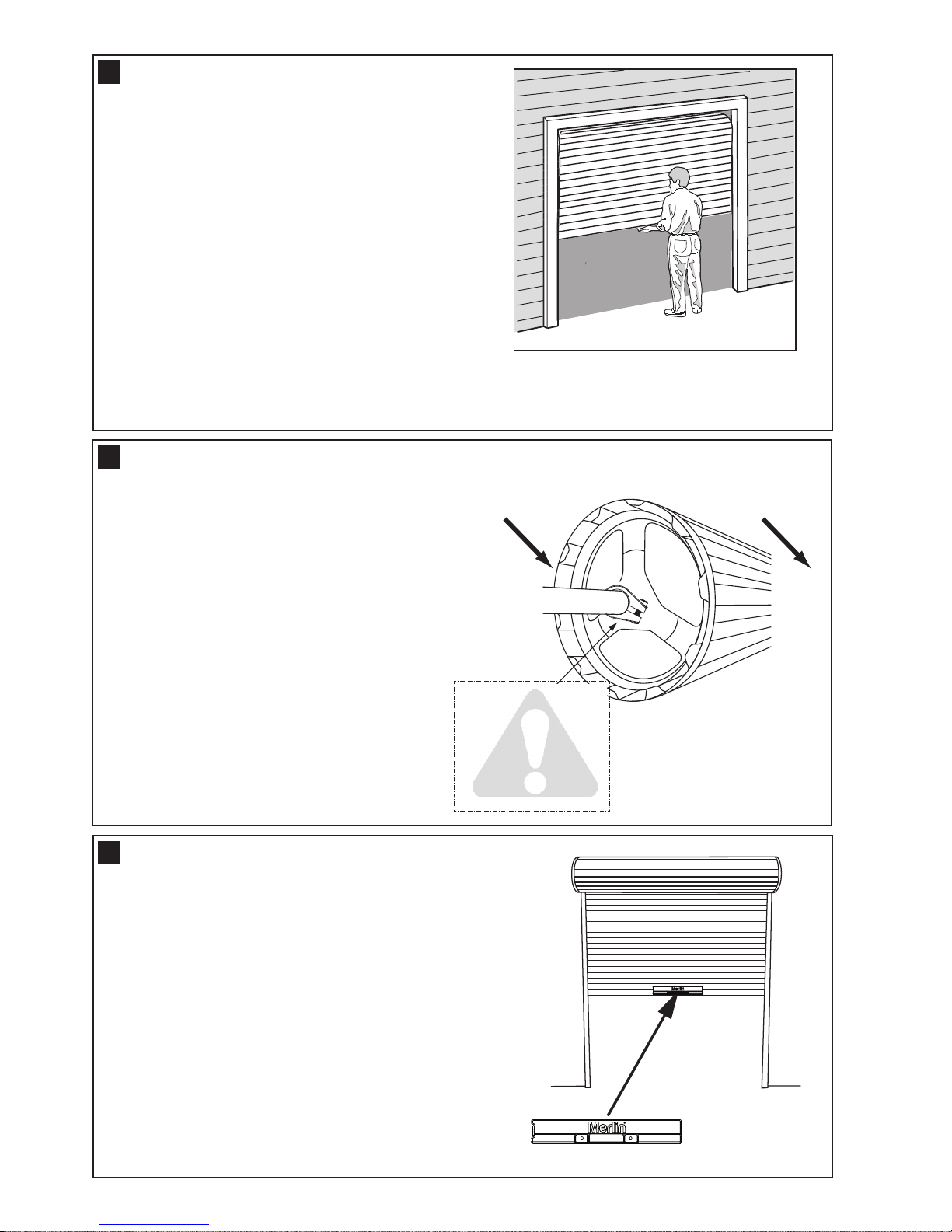
Complete the following test to ensure your door is well
balanced, and not sticking or binding:
• Disable all locks and remove any ropes connected to the
garage door.
•
Lift the door to about halfway and then release it. The
door should remain spring balanced.
• Raise and lower the door to determine if there are any
sticking or binding points (15 kgf is the absolute maximum
allowable to raise or lower the door in any position).
• If your door does not hold in place or the door binds or
sticks, call a qualified door technician before installing the
opener.
• The stop collar (inset 1) is required to be installed on
the opposite side of the door to where the opener is
to be installed.
• Ensure the U-Bolt holding the door shaft to the door
bracket is tightly secure.
(NOTE: This U-Bolt must not be removed or loosened)
• Remove the bolt assembly from the plastic stop
collar. Open the collar as wide as possible and push
it onto the door shaft.
• Fit the stop collar hard against the boss of the
door drum. Reinstall the bolt assembly onto the
stop collar and tighten.
6
1
2
3
4
7
6
5
DNDN UPUP PP SS
11
22 33
8
4 3 2 1
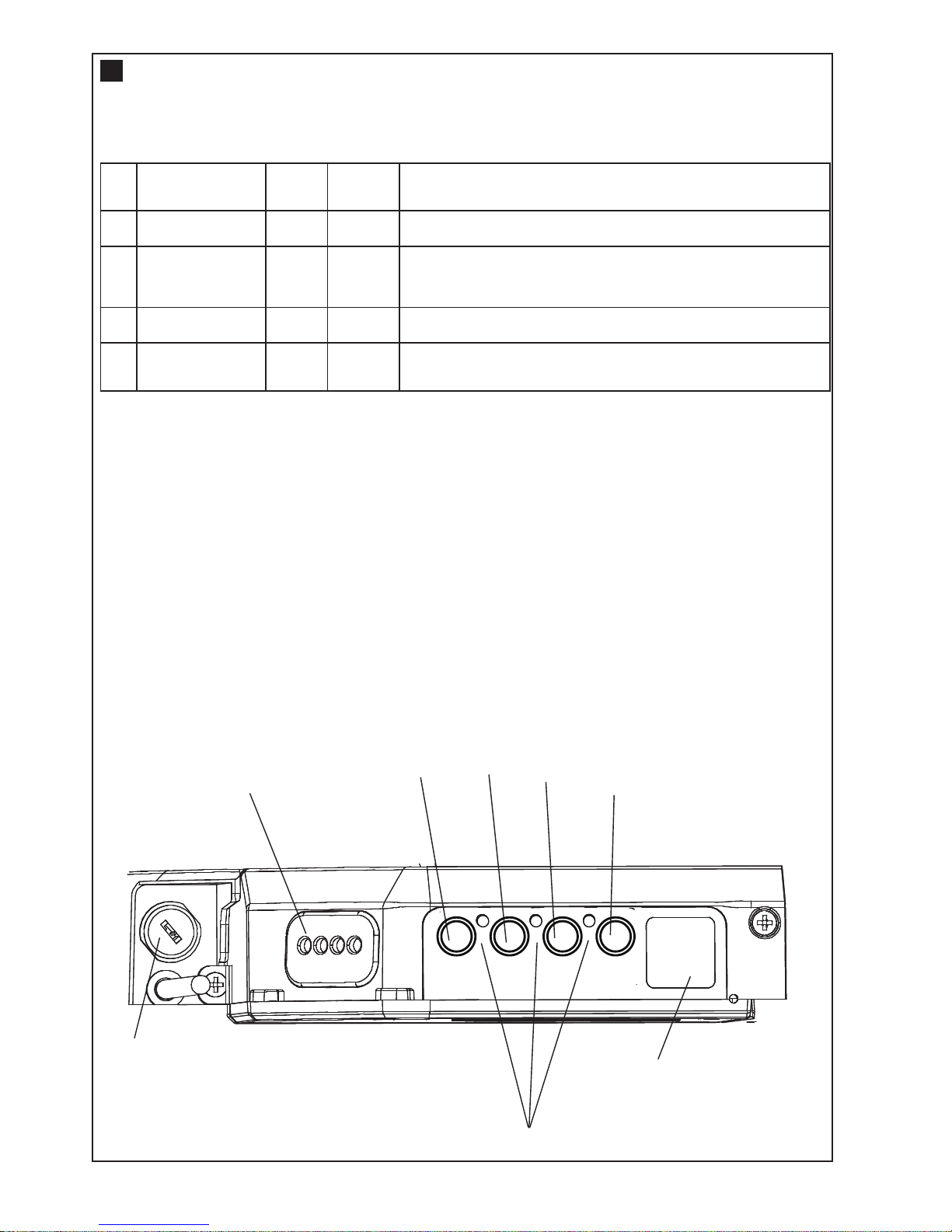
1
. Terminal Block: used for external accessories (see chart below).
NOTE: The terminal block is weather protected by a rubber grommet.
When using external wiring, the cable holes can be punched through with a small screwdriver. These holes
should be sealed with silicon sealant in order to maintain the weather proof rating.
2. DN Button: used to drive door DOWN.
3. UP Button: used to drive door UP.
4. P Button: used to “PROGRAM” the DOOR LIMITS.
5. S Button: used to “SAVE” the “REMOTE CONTROLS”.
6. Key Lock: used to lock the engage/disengage mechanisim for commercial applications.
7. LEDs: 1. Program DOWN, and Diagnostic code indicator Number 1.
2. Program UP indicator.
3. Diagnostic code indicator Number 2.
8. Courtesy Light: turns on during operation and automatically turns off after 3 minutes.
No Function
Colour
Polarity Comment
1
Push button
Red
+ve
Dry contact input for push button wired wall controls:
2
Common
White
-ve
Common terminal for push button, IR Beams & accessory
power:
3 IR Beams
Grey
+ve
IR Beam Input: (pulsing type only)
4
Accessory Power
Green
+ve
24v dc 50 mA accessory output available for a universal
receiver (output not active in Low Standby mode)
C
ONTROL PANEL
7
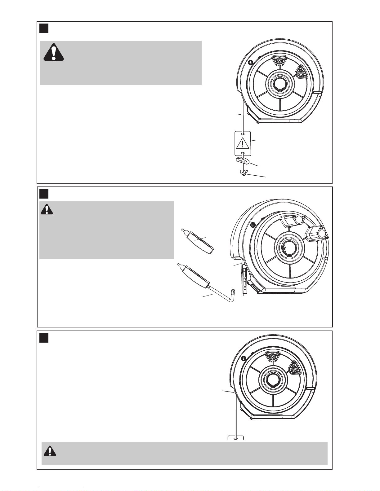
Rope
Manual release
warning label
R
elease handle
Overhand knot
THE RELEASE HANDLE & CORD
8
7
Unlock
NOTE: Ensure the Key Lockable Release is not locked.
To disengage the opener
Pull the release cord down firmly,
(opener will make a clicking noise).
To re-engage the opener
Pull the release cord down firmly,
(opener will make a clicking noise).
Disable all locks and remove any ropes connected to the garage door.
Take care when operating the manual release as an open door may fall rapidly due to weak or
broken springs, or being out of balance.
OPERATING THE MANUAL RELEASE
10
The manual release mechanism enables the door to be
m
anually operated during power outages or in an emergency.
The RED Manual Release cord is preassembled to the
opener. When the opener is installed the handle should be no
higher then 1.8 metres from the floor. The cord may need to
be extended.
DO NOT DISENGAGE THE OPENER TO MANUAL
OPERATION WITH CHILDREN , PERSONS OR
OTHER OBJECTS INCLUDING MOTOR VEHICLES
WITHIN THE DOORWAY : (The door is under significant
tension and if the door has developed a fault or incorrect
tension, it may be unsafe and may fall rapidly.)
Lock or unlock
a
s required
I
nsert key into
Release Handle
8 mm allen key
(not provided)
• Turn OFF the opener mains power (so the door
cannot be activated).
• Insert the key into the Maual Release handle and
Lock or Unlock as required (an 8 mm allen key
can be used to extend the handle if needed).
• Keep the key in a safe place.
• Two keys are provided, if a replacement is needed,
refer to a locksmith.
KEY LOCKABLE RELEASE
9
The use of the Key Lockable Release is
for use in Commercial Applications
ONLY, and not to be used when installed
in a residential Application (refer safety
standard AS/NZS 60335.2.95). An
alternative exit path from the building
MUST BE AVAILABLE when using the
Key Lockable Feature
 Loading...