

Page 1
INSTRUCTION MANUAL
English - 1-10
Deutsch - 11-20
Français - 21-30
Español - 31-40
ML47999
5
050864 01118 1
Page 2
HAVE FUN! But please read this first !!
We know you will have great fun with your model, but to get the best from your purchase please read this information BEFORE you operate the
model.
Table of contents
Page
Warranty 1
Specifications 2
Items required for operation 2
Glossary 2
Safety Precautions 2
Charging the battery pack 2
Transmitter 3
Controlling your Helicopter 4-5
Trimming Adjustments and Control Tests 6
How to Fly 7
Troubleshooting 7
Replacing the Blades 8
Fine Tuning of YAW Control 8
Parts List Tracer 180 9
Parts List Tracer 240 10
Tracer 180 Exploded Diagram 41
Tracer 240 Exploded Diagram 42
90 Day Component Warranty
We want you to enjoy your purchase, but please read this first!
This product is covered by a 90 day component warranty from date of purchase. If any part of the product fails as a result of faulty manufacture
during this period then we will repair or replace that part at our discretion.
We do not operate a new for old warranty once the product has been used.
Please note this product is not a toy and it is recommended that children 14 and under are supervised by an adult. It is the responsibility of the
parent or guardian to ensure minors are given appropriate guidance and supervision.
If you suspect there is a problem with the product, for whatever reason, it is the user’s responsibility to investigate and take steps to rectify the
problem before further damage occurs.
Not Covered By Warranty
This is a sophisticated, high performance model and should be treated with care and respect. Every effort has been made to make this product as
strong and durable as possible, however due to the nature of this product, it is still possible to break or damage parts through crashing or extreme
use. Components damaged as a result of crash damage, improper use, lack of maintenance or abuse is not covered by the warranty.
How to Claim Against your Warranty
For warranty claims please first contact your supplying retailer. Do not return the product to your distributor without their prior approval. You may
not need to return the product in full, only the damaged component along with a copy of your purchase receipt. In many cases it is faster and more
cost effective for the user to fit the replacement part(s) to the product & therefore we reserve the right to supply parts only in these instances.
Any returned component that is inspected by your distributor and found to have an invalid warranty claim may be subject to an inspection and
handling fee before it can be returned. Any repairs required as a result of neglect or misuse will be charged before any work is carried out on the
product. If you decide not to have any work carried out the distributor reserves the right to charge a handling and a shipping fee.
Please attach your proof of purchase in the manual as you may need it again in the future.
1
Page 3
2
Items required for operation
4 * AA Batteries for the Transmitter
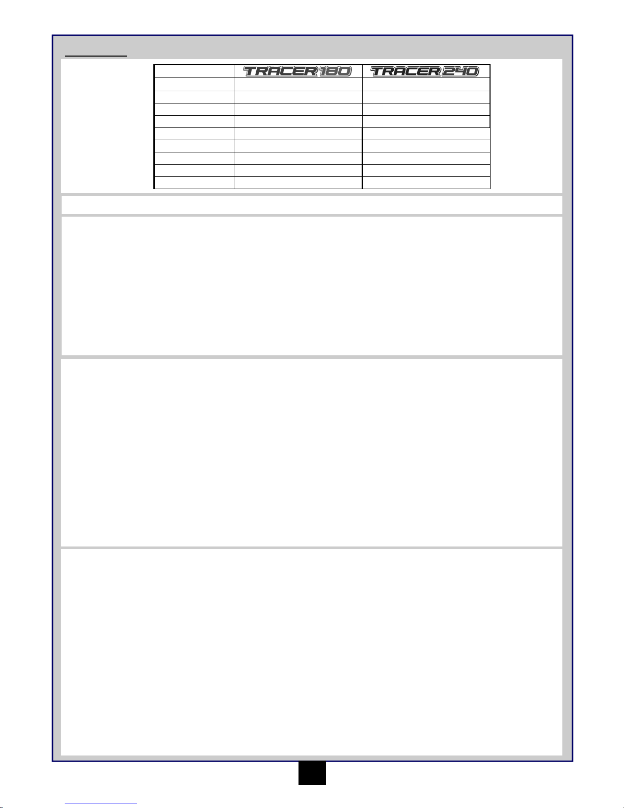
Specification
Glossary
Landing gear - Legs on the underside of helicopter.
Rotor - High speed rotating blades used to lift the helicopter into the air.
Throttle - A control function to adjust the speed of the rotating blades & height of the helicopter.
Rudder - A control function to turn the helicopter.
Cyclic Controls - Control functions to move the helicopter in flight.
Fuselage - Main body of the helicopter containing motor, receiver, speed control, servos and battery
Gyro - An electronic stabiliser built into the helicopter to assist flight.
LED - A coloured indicator light.
Swash Plate - Rotating plate below the rotor that adjusts the blade angles.
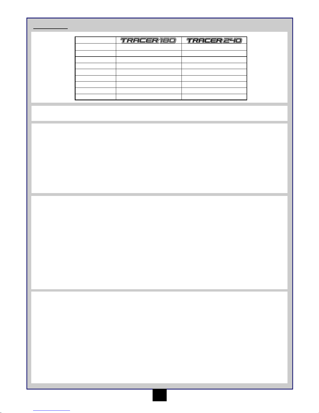
Tracer 180 Tracer 240
Main Rotor Diameter 340mm 380mm
Fuselage Length 355mm 355mm
Flying Weight 231.5g 185g
Motor 180 Size Brushed 180 Size Brushed
Battery 7.4V 800 mAh Li-Po Battery 7.4V 800 mAh Li-Po Battery
Transmitter MTX-472 2.4 GHz 4 Channel MTX-472 2.4 GHz 4 Channel
Receiver MRX-47-2 2.4 GHz 4 in 1 Board MRX-47-1 2.4 GHz 4 in 1 Board
Servos 2 x Micro Servos 2 x Micro Servos
Charger Mains 240V Li-Po Balance Charger Mains 240V Li-Po Balance Charger
Safety Precautions
• Read and follow this manual completely, observing all instructions and safety directions. Otherwise, serious injury and damage can occur.
Think about your safety, and the safety of others, first.
• Hold the product securely when the flight battery is plugged in, keep the rotor away from body parts and clothing, even it isn’t spinning, as
it could be turned on by accident. Beware of hair becoming entangled in the rotor.
• Do not fly when it’s too windy or you may lose control and crash, causing injury or damage. Never fly near people, vehicles, train tracks,
buildings, power lines, water, hard surfaces or trees. Never allow anyone to attempt to catch the model while it’s in flight or serious injury
may result.
• Adult supervision for flying and battery charging is recommended for pilots age 14 and younger.
• Only use a battery charger that is compatible with the flight battery. Never leave the charger unattended while charging. This will help
prevent overcharging and make sure damage does not occur to the battery, charger or any other property. While charging, place the
battery on a heat-resistant surface. Do not lay it on carpet or upholstery while charging.
• Never cut into the battery, charger, or aeroplane wires or serious injury may occur. Causing the battery to “short out” (crossing negative
and positive bare wires) can cause fire, serious injury and damage.
• When you finish flying your product, always unplug the battery before you turn off the transmitter.
• Always check that the transmitter has full control of the helicopter before flying.
Charging the battery pack
Use the supplied charger to charge the supplied battery. Other products are available and if used, you must follow the products instructions to
avoid damage.
The typical charge time for a flat battery is 110 minutes.
1. Connect the 240V wall mounted transformer (12V output) to the input side of the supplied charger, the red power indicator should glow.
2. Plug the battery into the 7.4V 2-cell output socket of the charger. The charge indicator should glow red to indicate charging is taking place.
3. When charging is complete the charger will automatically stop charging and the charge indicator will glow green.
4. Unplug the battery and input to the charger.
Cautions
• Use the charger with adult supervision. Do not use the charger near water or when wet.
• Do not use the charger if the wire is frayed or worn. If the wire is frayed or worn a short circuit can cause a fire or burns.
• If your battery gets hot and exceeds 50 degrees C during charge it may be faulty and you should contact your retailer
• If the battery pack bulges or expands during charge or use it is faulty and you should contact your retailer.
• Never leave your battery pack on charge unattended.
Introduction
Page 4

3
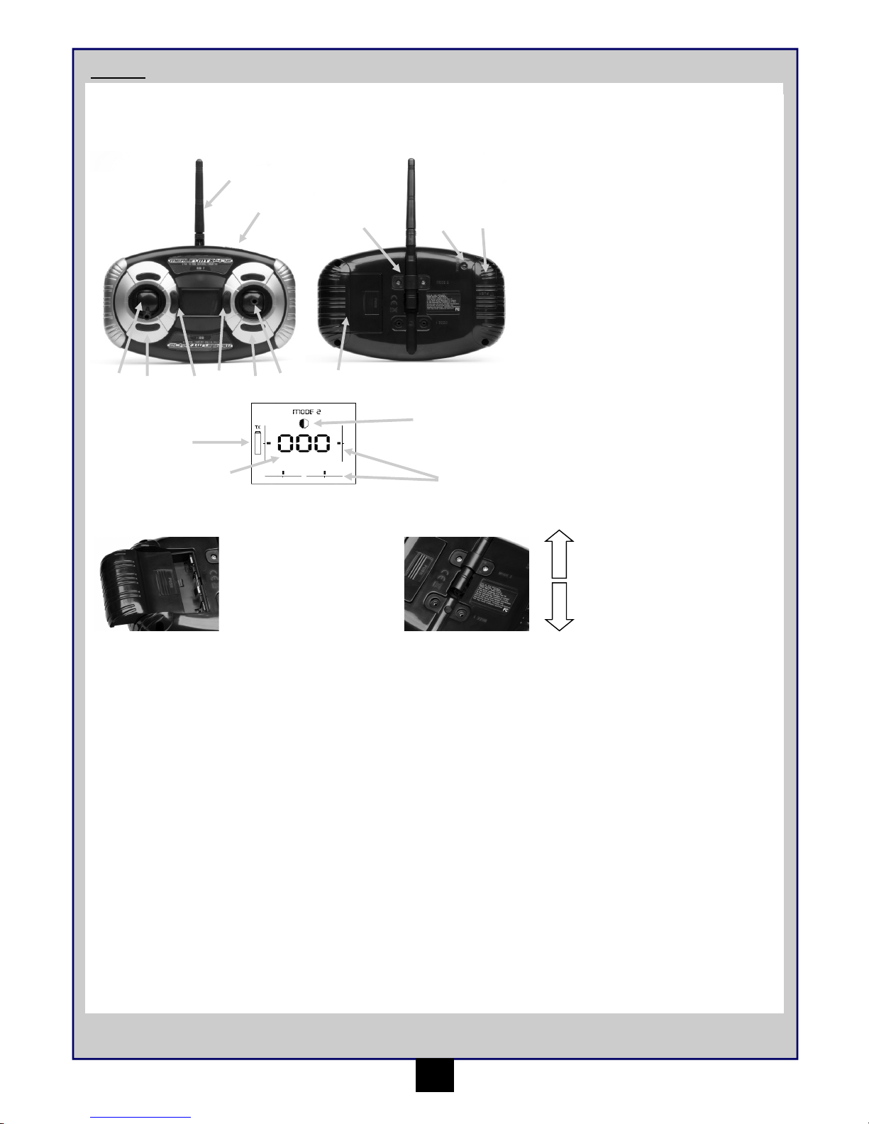
Transmitter
Transmitter Controls
Preparing the transmitter
Make sure the aerial on the
transmitter is in the mode position
of your choice and is held in
position with the bracket and
screws provided.
1. Aerial
2. Throttle Trim
3. Rudder Trim
4. Cyclic L/R Trim
5. Cyclic F/B Trim
6. Mode 2 - Throttle Stick (Binding Button)
6. Mode 1 - Cyclic Control Stick (Primary to
Advanced Button)
7. Mode 2 - Cyclic Control Stick (Primary to
Advanced Button)
7. Mode 1 - Throttle Stick (Binding Button)
8. Power Switch
9. Battery Level Indicator
10. Primary or Advanced Mode Indicator
11. Trim Indicators
12. Throttle Reading
13. Charge Port Cover (Not Used on Tracer
180/240)
14. Main Battery Cover
15. Aerial Clip
16. Charge LED Indicator (Not Used on
Tracer 180/240)
Open the battery holding tray to
expose the empty battery slots.
Insert 4 AA batteries into the
marked spaces. Please note the
correct direction of the batteries.
Incorrect battery insertion could
lead to damage.
Mode 2
Mode 1
Your Merlin Transmitter is an advanced controller designed for the beginner to be easy to use and tune. You will need to follow the steps below to
ensure you prepare the controller correctly for use and understand the adjustment possibilities available.
Switching the transmitter “Mode” from Mode 2, to Mode 1.
The MTX - 472 Transmitter has the ability to offer two options for transmitter control. (Controls shown in full in “Controlling your Helicopter
section of the manual)
1. With the transmitter turned off, remove the aerial clip from the back of the transmitter.
2. Fold the aerial back so that it is at 90 degrees from the transmitter case and rotate 180 degrees. The aerial will then fold back into the
groove on the opposite site of the case.
3. Reinstall the aerial clip with the screws.
4. Turn on the transmitter. The LCD screen will now read MODE 1 (To switch back to Mode 2, use the same process)
Binding the transmitter to the model.
This is needed in the event that the model needs to be bound to either your transmitter or a replacement transmitter. The model will not respond to
an unbound transmitter.
1. Whilst turning the transmitter on, hold down the Throttle Stick button. You will hear a beeping sound and a line flashes on the LCD screen.
2. Plug in the battery pack on the model. After a few seconds the LED on the model turns a solid red and the transmitter reverts to normal
flight mode. Your model and transmitter are now bound together for interference free flight!
Switching Off
Unplug the helicopter battery followed by switching off the transmitter. Always follow this procedure when switching off.
10
12
11
9
1
4
6 2 3 5
7
8
14
1316
15
Page 5
4
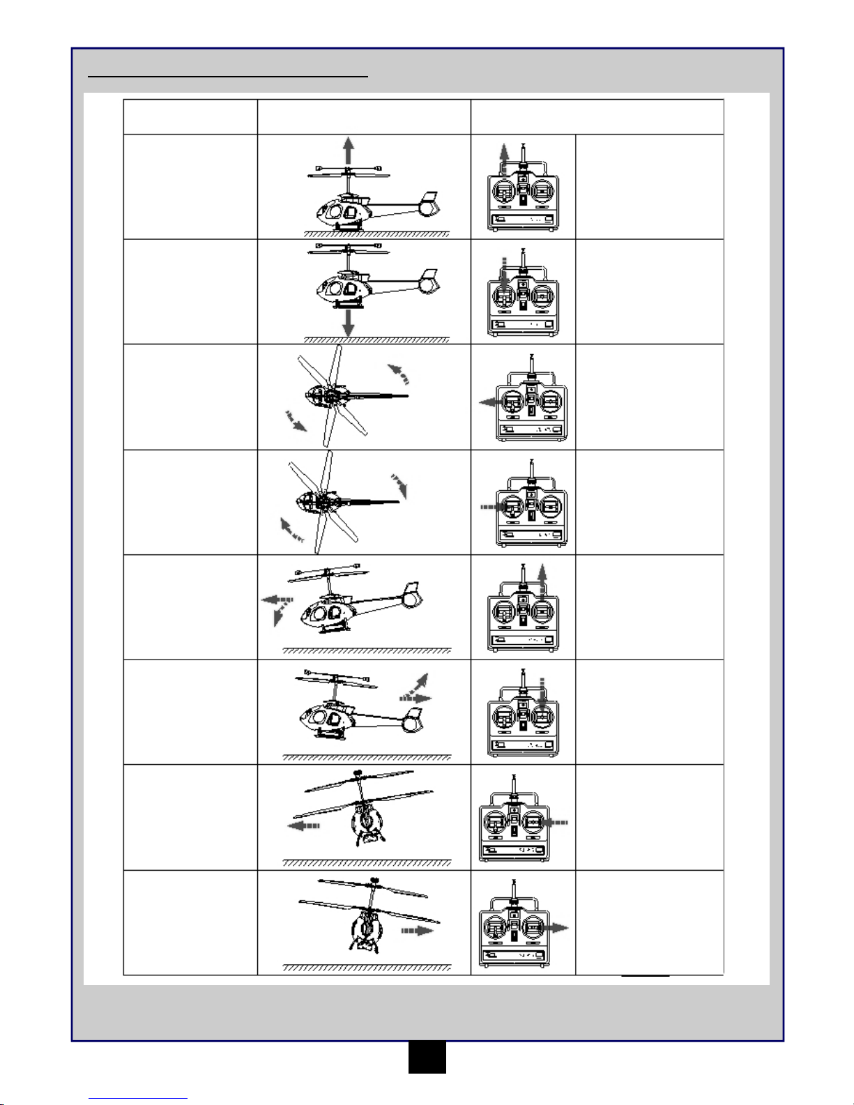
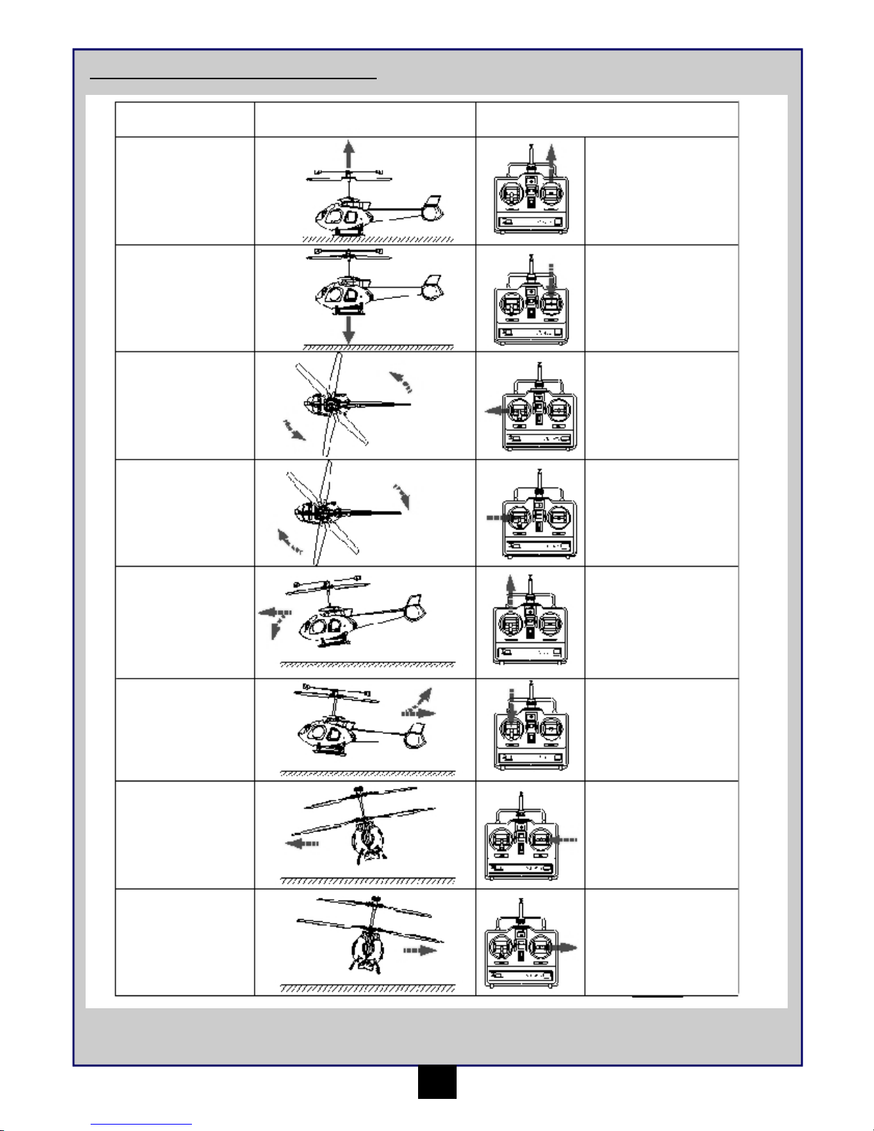
Main body lifts up
Main body lowers
The nose will turn to
the left
The nose will turn to
the right
The nose will dive
and move forwards
The nose will raise
and move back-
wards
The body will pitch
to the left
The body will pitch
to the right
Push throttle stick
forwards
Pull throttle stick
backwards
Push the rudder stick
to the left
(Move trim lever to
right)
Push the rudder stick
to the right
(Move trim lever to
left)
Push the cyclic control
stick forwards
(Move trim lever back-
wards)
Pull the cyclic control
stick backwards
(Move trim lever
forwards)
Push the cyclic control
stick to the left
(Move trim lever right)
Push the cyclic control
stick to the right
(Move trim lever left)
Actions Transmitter & (Trimming ) Input
Controlling your Helicopter in Mode 2
Page 6
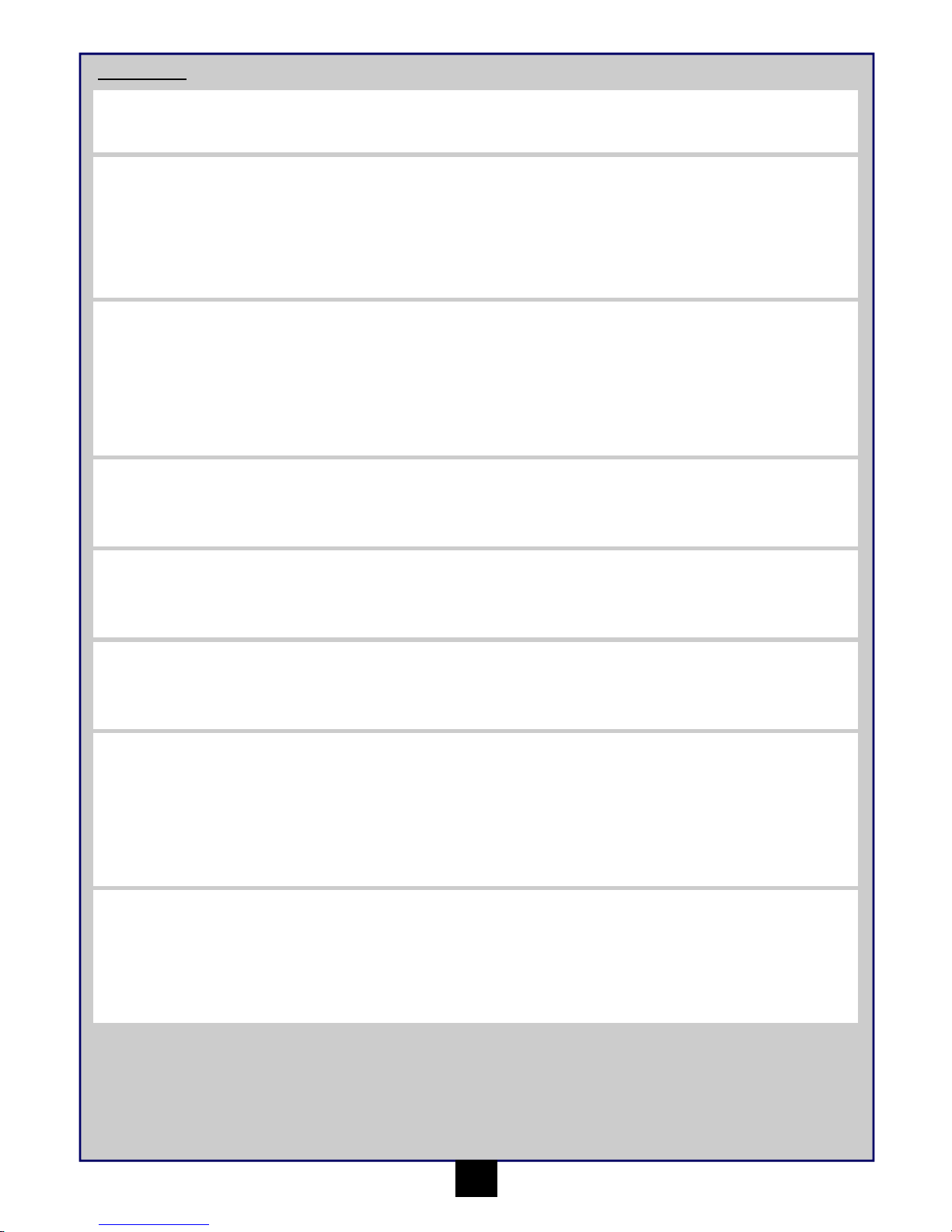
5
Main body lifts up
Main body lowers
The nose will turn to
the left
The nose will turn to
the right
The nose will dive
and move forwards
The nose will raise
and move back-
wards
The body will pitch
to the left
The body will pitch
to the right
Push throttle stick
forwards
Pull throttle stick
backwards
Push the rudder stick
to the left
(Move trim lever to
right)
Push the rudder stick
to the right
(Move trim lever to
left)
Push the cyclic control
stick forwards
(Move trim lever back-
wards)
Pull the cyclic control
stick backwards
(Move trim lever
forwards)
Push the cyclic control
stick to the left
(Move trim lever right)
Push the cyclic control
stick to the right
(Move trim lever left)
Actions Transmitter & (Trimming ) Input
Controlling your Helicopter in Mode 1
Page 7

6
Trimming Adjustments and Control Tests
Installing the battery
To install the Li-PO battery into the
fuselage insert the charged battery
into the bottom of the helicopter
base.
Checklist
Each time before you start flying your Merlin Flight Product, please carry out the following checks and tests.
• Make sure the Swash plate has free movement
• All screws, bolts, etc. are tight
• Radio equipment is securely fastened inside fuselage
• Batteries are fully charged.
• No wires interfere with servo motors
• Blades are securely fastened
Control Test
• Be certain that the throttle stick is in the “off” position. - 000
• Switch on the transmitter, make sure the aerial is upright and check to make sure the Power indicator is full. If the indicator is empty and
flashing then the transmitter batteries are low on power and must be replaced before flying.
• Plug in the helicopter battery and wait for the receiver power light to stop flashing to confirm the unit has calibrated.
• Place your model on the ground and walk away whilst operating the swash plate controls.
• Check that the servos operate without interference up to a distance of 30 metres.
• Gently move the throttle stick forwards to check the main blades rotate.
3. If while flying, you notice the model drifts in any direction without you operating the controls, the model
can be trimmed using the trim tabs on the transmitter.
4. The trim tabs offset the centre position of the control stick to regain the models natural equilibrium.
5. Each Trim tab moves the centre position in the direction indicated on the tab, this is always from the
perspective of the helicopter cabin facing away from the operator.
6. If the model is drifting left, add a step of right trim. If the model is drifting forwards, add a step of back
trim. These both work for the opposite directions.
7. The throttle trim will generally not be needed as the model will not configure on start up if the throttle is
not set at zero. The only other trim is the rudder trim. If the model spins on its centre axis then the
rudder trim can be adjusted to compensate. Left trim is used if the canopy is spinning clockwise and
right trim if it spinning anti-clockwise.
1. Switch on your transmitter and make sure the throttle stick is fully pulled back. - 000
2. Make sure the battery is plugged in. Leave the helicopter until you see the power light stop flashing and remain constant to confirm
the unit has calibrated.
Trimming Check
At all times the trim positions are shown on the LCD screen. The Indicator will move up and down the trim line
to show how much trim is currently being used. Once adjusted the trim will remain saved in those positions for
use next time. The transmitter will beep once when the trim is at the centre position for easy identification.
There are two flight modes for the Tracer to help you get the most out the performance. Primary mode gives a basic speed and range of
movement from the controls and is the most stable of the two. The advanced mode gives a higher level of speed and movement from the controls
to give you a more hands on feel.
• The flight characteristics can be adjusted at any time while the transmitter is
turned on by pressing down the Cyclic control stick button.
• The transmitter will beep and the Primary/Advanced mode indicator change from
a half circle for Primary to a full circle for Advanced.
Advanced flight Characteristics Button
Page 8
7
How to Fly
Learning to Hover
1. Place your helicopter in a an open space facing away from yourself about 5 metres in distance.
2. Push the throttle stick gently forwards increasing the blade speed until it becomes light just lifting from the ground.
3. Gently decrease the power to land smoothly.
4. If your helicopter moves away from the centre of your training area place it back in the middle.
5. Repeat this exercise increasing the flying height of 1 metre can be achieved whilst remaining in control.
All helicopters experience some instability immediately on lifting from the ground. If this does not stabilise as height is gained and your helicopter
drifts or turns repeatedly in one direction you will need to adjust the transmitter trim levers. To do this refer to Controlling Your Helicopter and
move the transmitter trim lever one or two clicks in the opposite direction to the travel until a steady hover is achieved.
Experience
Your Tracer helicopter makes an ideal introduction to flying RC Helicopters and by following the following basic instructions inexperienced pilots
should soon master basic flying skills.
Learning to Turn
1. Hover your helicopter 1 metre in the air.
2. Move the rudder stick a small amount in one direction and release it. The tail of your helicopter will swing around and stop in the new
position.
3. Repeat applications of rudder so you can turn and hover facing in any chosen direction.
Site & Conditions
• Fly your helicopter indoors in a large room, hall or office. Only fly outdoors in perfectly calm conditions with no wind unless you are an
experienced pilot.
• Make sure there are no obstacles that will get in your way when flying, such as furniture, trees or buildings.
• Make sure you do not fly where there are people or animals who could be hurt by the helicopter.
• If flying outdoors position yourself so that you keep the sun at your back and out of your eyes. Wear sunglasses on bright days.
• Keep your helicopter in front of you so you don’t have to turn in circles as you fly. Try to avoid flying directly overhead.
Learning Forward and Backwards Flight
1. Hover your helicopter 1 metre in the air.
2. Move the cyclic control stick forwards gently and release it, your helicopter will move forwards then hover stationary.
3. Reduce the throttle stick and land your helicopter returning it to its starting position.
4. Repeat this exercise but prior to landing move the cyclic stick back to return the helicopter to its starting position whilst in flight.
Learning Sideways Flight
1. Hover your helicopter 1 metre in the air.
2. Move the cyclic control stick sideways gently and release it, your helicopter will move sideways then hover stationary.
3. Reduce the throttle stick and land your helicopter returning it to its starting position.
4. Repeat this exercise but prior to landing move the cyclic stick back to return the helicopter to its starting position whilst in flight.
Combining Controls
1. Hover your helicopter 1 metre in the air.
2. Move the cyclic stick forwards and hold its position to achieve a slow forward flight.
3. Move the rudder stick left or right and your helicopter will begin to fly in a circular motion.
4. Practice turning left and right circles of small and large diameters.
By combining control inputs you will be able to control your helicopter position accurately and fly in more advanced patterns such as figure of eight
or carry out simple aerobatic manoeuvres.
Once confidence and control has been gained experiment by increasing the hovering height to 2 to 3 metres and combining forwards, backwards,
sideways and turn controls.
Tips for Success
• Only operate the throttle stick gently with small inputs, the most common form of damage is due to reducing the throttle by large amounts
causing sudden reductions in height and crashing.
• When your helicopter begins to climb slowly or is unable to climb on full throttle then the battery is beginning to run low, for safety land
your model as soon as possible and re-charge.
• Damage or bends to the blades or fuselage can greatly affect flight control. Replace damaged parts immediately.
• Don’t attempt to fly or do manoeuvres beyond your flying abilities.
Page 9

8
Problem Cause Solution
Unit does not operate Transmitter “AA” batteries are depleted or
installed incorrectly, indicated by a dim or
unlit LED on transmitter or the low battery
alarm.
Check polarity installation or replace with
fresh “AA” batteries.
No electrical connection. Push connectors together until they “click.”
Main motor does not turn 4-in-1 unit not operating correctly Consult your retailer
Helicopter spins uncontrollably Gyro gain is incorrectly setup Adjust Gyro gain to 90%
Helicopter will not hover still when sticks
are neutral
Trimming incorrect or swash plate is not
level
Adjust trim levers or adjust Swash plate
Vibration Bent main shaft Replace main shaft
Blades are broken Replace blades
Troubleshooting
Helpful Information
Replacing the Blades
Your Tracer helicopter is supplied with a spare set of replacement blades in the event of crash damage. Should you need to replace the blades
please follow these simple steps :-
1. The blades are fastened with a screw and can be removed very easily
2. Loosen the screw on the damaged blade and remove it allowing the blade to come off
3. Insert the new blade into the gap and replace the screw tightening only sufficient to make sure the blade still moves freely.
Fine Tuning of YAW Control
The YAW controls are pre set from the factory and test flown and should not need adjustment. However for tuning by experienced pilots or in the
event of a serious crash and the need to re-build your helicopter their adjustment and function is as follows :-
Gyro gain - the gyro detects rotary movement and will stabilise the tail automatically in flight. The Gyro gain dial adjusts the sensitivity from
0 - 100%, the best setting is around 90% as pre-set. When the setting is too high the tail will be seen to wag from side to side, making it unstable.
Adjust the dial to compensate. Clockwise will reduce the amount of gyro gain.
Throttle mixer - the throttle mixer is the balance between the two motors on the helicopter. When the throttle is applied the mixer directs power to
the second set of blades to compensate for the torque of the other motor and blades. When this is in equilibrium and throttle is applied the
helicopter will gain height without spinning left or right. Clockwise will make the helicopter rotate to the right. The Throttle Mixer for the Tracer 240
also functions the same way. However it is the balance between the main motor and tail motor instead of the two main motors of the Tracer 180.
Page 10
9
Parts List
ML47001
MRX-47-2 Receiver/ESC/Gyro (Tracer
180)
023 MRX-47-2 Receiver/ESC/Gyro
ML47002 Rotor Blades 4pcs (Tracer 180)
001 Upper Main Rotor Blades
012 Lower Main Rotor Blades
ML47003 Battery 7.4V 2 Cell 800mah (Tracer 180)
047 Battery 7.4V 2 Cell 800mah
ML47004 Rotor Blade Grip Set (Tracer 180)
002 Rotor Blade Grip Set
ML47005 Cabin Set - Red (Tracer 180)
018 Rubber O Ring
019 Cabin
021 LED Light Mounts
051 Fuselage Rear Section
053 Exhaust
ML47006 Tail Set - Red (Tracer 180)
054 Tail
056 Vertical Tail
057 Top Tail Wing
ML47007 Flybar Set (Tracer 180)
003 Flybar
004 Weight Block
005 Hammer Balance
006 Upper Ball Linkage Rod
ML47008 Battery Frame (Tracer 180)
048 Battery Frame
049 Battery Cover Board
ML47009 Landing Skid Mount (Tracer 180)
045 Landing Skid Mount
ML47010 Tail Blade Set (Tracer 180)
058 Tail Blade Support
059 Tail Blade
060 Tail Blade Shaft
ML47011 Screw Set (Tracer 180)
015 Screw 1.7x4
024 Screw 1.7x4
025 Screw 2x6
026 Screw 1.7x4
031 Screw 2x3
037 Screw 2x4
040 Screw 1.7x2.5
043 Screw 2x4
046 Screw 1.7x4
055 Screw 1.7x6
061 Screw 1.7x4
ML47012 Motor Set (Tracer 180)
017 Front Motor
035 Rear Motor
ML47013 Outer Shaft Set (Tracer 180)
009 Bearing Board
010 Spindle
ML47014 Ball Linkage Rod Set (Tracer 180)
011 Middle Ball Linkage Rod
016 Under Ball Linkage Rod
ML47015 Gear Set (Tracer 180)
039 Upper Gear
042 Lower Gear
ML47016 Bearing Set (Tracer 180)
008 Bearing MR52zz
033 Bearing MR74zz
038 Bearing MR74zz
041 Bearing MR52zz
ML47017 Collar Set (Tracer 180)
031 Screw 2x3
032 Positioning Collar
043 Screw 2x4
044 Positioning Collar
ML47018 Under T Shape Holder (Tracer 180)
027 Under T Shape Holder
ML47019 Main Frame (Tracer 180)
034 Main Frame
ML47020 Inner Shaft (Tracer 180)
007 Inner Shaft
ML47039 Micro Servo 5g (Tracer 180)
013 Servo
014 Servo Horn
015 Screw 1.7x4
ML47040 Balanced Charger (Tracer 180/240)
ML47041 Power Adaptor (CH) (Tracer 180/240)
ML47042 Power Adaptor (AU) (Tracer 180/240)
ML47043 Power Adaptor (EU) (Tracer 180/240)
ML47044 Power Adaptor (US) (Tracer 180/240)
ML47045 Power Adaptor (UK) (Tracer 180/240)
ML47046 Landing Skids (Tracer 180/240)
050 Landing Skids
ML47047 LED Navigation Lights (Tracer 180/240)
020 LED Lights
ML47048 Swashplate Set (Tracer 180/240)
028 Upper Swashplate
029 Bearing 137zz
030 Lower Swashplate
ML47049 ScrewDriver
ML47054
MTX-472 Transmittor 2.4Ghz and Mode
Reversible
Page 11
10
Parts List
ML47021
MRX-47-1 Receiver/ESC/Gyro (Tracer
240)
035 MRX-47-1 Receiver/ESC/Gyro
ML47022 Rotor Blades 2pcs (Tracer 240)
008 Main Rotor Blades
ML47023 Battery 7.4V 2 Cell 800mah (Tracer 240)
042 Battery 7.4V 2 Cell 600mah
ML47024
Main Rotor Blade Grip & Mixed Rocker
(Tracer 240)
005 Mixed Rocker
007 Rotor Blade Grips
012 Screw 1.7x4
ML47025 Cabin Set (Blue) (Tracer 240)
028 Rubber O Ring
036 Cabin
038 LED Light Mounts
046 Fuselage Rear Section
048 Exhaust
ML47026 TailSet (Blue) (Tracer 240)
052 Vertical Tail
053 Tail
055 Tail Top Wing
ML47027 Flybar Set (Tracer 240)
001 Weight Block
002 Hammer Balance
003 Flybar Set
004 Upper Ball Linkage Rod
ML47028 Main Shaft Set (Tracer 240)
006 Upper T Shape Holder
010 Screw 1.7x4
014 Spindle
ML47029 Ball Linkage Rod Set (Tracer 240)
013 Middle Ball Linkage Rod
031 Lower Ball Linkage Rod
ML47030 Collar Set (Tracer 240)
018 Screw 2x3
019 Positioning Collar
ML47031 Main Frame Set (Tracer 240)
020 Canopy Support
021 Screw 1.7x4
023 Main Frame
047 Canopy Mount
ML47032 Gear Set (Tracer 240)
034 Main Gear
ML47033 Bearing Set (Tracer 240)
022 Bearing MR74zz
024 Bearing MR74zz
ML47034 Battery Frame (Tracer 240)
041 Battery Frame
044 Battery Cover Board
ML47035 Landing Skid Mount (Tracer 240)
039 Landing Skid Mount
ML47036 Screw Set (Tracer 240)
009 Screw 2x6
010 Screw 1.7x4
011 Screw 1.7x4
012 Screw 1.7x4
018 Screw 2x3
021 Screw 1.7x4
025 Screw 2x3
032 Screw 1.7x4
033 Screw 1.7x2.5
040 Screw 1.7x4
045 Screw 1.7x4
054 Screw 1.7x6
056 Screw 1.7x2.5
ML47037 Main Motor Set (Tracer 240)
026 Main Motor
027 Pinion Gear
ML47038 Tail Motor Set (Tracer 240)
049 Tail Blade
050 Motor Mount
051 Rear Motor
056 Screw 1.7x4
ML47052 Micro Servo 5g (Tracer 240)
029 Servo
030 Servo Horn
045 Screw 1.7x4
ML47040 Balanced Charger (Tracer 180/240)
ML47041 Power Adaptor (CH) (Tracer 180/240)
ML47042 Power Adaptor (AU) (Tracer 180/240)
ML47043 Power Adaptor (EU) (Tracer 180/240)
ML47044 Power Adaptor (US) (Tracer 180/240)
ML47045 Power Adaptor (UK) (Tracer 180/240)
ML47046 Landing Skids (Tracer 180/240)
043 Landing Skids
ML47047 LED Navigation Lights (Tracer 180/240)
037 LED Lights
ML47048 Swashplate Set (Tracer 180/240)
015 Upper Swashplate
016 Bearing MR137zz
017 Lower Swashplate
ML47049 ScrewDriver
ML47054
MTX-472 Transmittor 2.4Ghz and Mode
Reversible
Page 12
VIEL SPASS! Aber lesen Sie bitte erst diese Anleitung !!
Wir wissen, dass Sie mit Ihrem Modell viel Spaß haben weden, aber BEVOR Sie das Modell in Betrieb nehmen, lesen Sie bitte erst diese
Informationen, damit Sie das Beste aus Ihrem Kauf machen können
Inhaltsverzeichnis
Seite
Garantie 11
Technische Daten 12
Für den Betrieb erforderlich 12
Glossar 12
Sicherheitsmaßnahmen 12
Batteriepack aufladen 12
Sender 13
Steuern des Hubschraubers 14-15
Trimmeinstellungen und Steuerungstests 16
Fliegen 17
Fehlersuche 17
Austauschen der Rotorblätter 18
Feintuning der Giersteuerung 18
Teileliste Tracer 180 19
Teileliste Tracer 240 20
Tracer 180 Explosionszeichnung 37
Tracer 240 Explosionszeichnung 38
90-Tage-Garantie auf Komponenten
Für dieses Produkt gilt eine 90-Tage-Garantie auf Komponenten ab dem Kaufdatum. Wenn während dieser Zeit ein Teil des Produkts infolge
Fabrikationsmängeln ausfallen sollte, liegt es in unsrem Ermessen, ob wir das Teil reparieren oder austauschen.
Wenn das Produkt einmal benutzt wurde, bieten wir keine Neu-für-Alt-Garantie.
Beachten Sie bitte, dass dieses Produkt kein Spielzeug ist und dass Kinder unter 14 Jahren von einem Erwachsenen beaufsichtigt werden sollten.
Es liegt in der Verantwortung der Eltern oder Aufsichtspersonen, sicherzustellen, dass Minderjährige entsprechende Anleitung und Aufsicht
erhalten.
Bei der Vermutung eines Problems mit dem Produkt, aus welchem Grunde auch immer, ist der Benutzer dafür verantwortlich, das Problem zu
untersuchen und für Abhilfe zu sorgen, bevor weitere Schäden entstehen.
Von der Garantie nicht gedeckt
Dies ist ein technisch ausgereiftes Hochleistungs-Modell, das mit Sorgfalt und Respekt behandelt werden sollte. Wir haben zwar alles getan, um
dieses Produkt so stabil und haltbar wie nur möglich zu machen, trotzdem können auf Grund der Natur dieses Produkts Teile bei
Zusammenstößen oder extremem Einsatz beschädigt werden oder brechen. Komponenten, die durch einen Unfall, falsche Verwendung,
mangelnde Wartung und Pflege oder Mißbrauch beschädigt wurden, fallen nicht unter die Garantie.
Garantieansprüche geltend machen
Mit Garantieansprüchen wenden Sie sich bitte zuerst an Ihren Händler. Ohne vorherige Genehmigung das Produkt nicht an den Distributor einschicken. Sie brauchen das Produkt nicht als Ganzes einschicken, nur die beschädigte Komponente zusammen mit einer Kopie des Kaufbelegs. In vielen Fällen ist es für Sie schneller und kostengünstiger, Ersatzteile in das Produkt einzubauen; daher behalten wir uns das Recht vor,
nur in solchen Fällen die Ersatzteile zu liefern.
Für jede eingeschickte Komponente, bei deren Überprüfung Ihr Distributor einen ungültigen Garantieanspruch festgestellt hat, werden Ihnen vor
der Rücksendung möglicherweise Prüfungs- und Bearbeitungskosten in Rechnung gestellt. Reparaturen, die als Folge von Nachlässigkeit oder
Mißbrauch erforderlich sind, werden in Rechnung gestellt, bevor Arbeiten am Produkt durchgeführt werden. Wenn Sie sich entscheiden, dass
keine Arbeiten ausgeführt werden sollen, hat der Distributor das Recht, Bearbeitungs- und Versandkosten in Rechnung zu stellen.
Sie sollten Ihren Kaufbeleg an dieses Handbuch anheften, für den Fall, dass Sie ihn später noch einmal benötigen.
11
Page 13
12
Für den Betrieb erforderlich - 4 * AA Batterien für den Sender
Technische Daten
Glossar
Landefahrwerk - Beine/Kufen auf der Unterseite des Hubschraubers.
Rotor - schnell rotierende Blätter, mit denen der Hubschrauber in die Luft gehoben wird.
Drossel - eine Steuerfunktion zur Regelung der Rotorgeschwindigkeit und der Flughöhe des Hubschraubers.
Seitenruder - eine Steuerfunktion zum Drehen des Hubschraubers.
Zyklische Steuerung - Steuerungsfunktionen zur Bewegung des Hubschraubers während des Flugs.
Rumpf - Körper des Hubschraubers, enthält Motor, Empfänger, Geschwindigkeitssteuerung, Servoantriebe und Batterie
Gyro - ein elektronischer Stabilisator, der als Flughilfe in den Hubschrauber eingebaut ist.
LED - eine farbige Anzeigeleuchte.
Taumelscheibe - rotierende Platte unterhalb des Rotors, über die der Blattanstellwinkel geregelt wird.
Tracer 180 Tracer 240
Hauptrotordurchmesser
340mm 380mm
Rumpflänge
355mm 355mm
Gewicht
231.5g 185g
Motor
180 er Elektro-Bürstenmotor 180 er Elektro-Bürstenmotor
Batterie 7.4V 800mAh LiPo Akku 7.4V 800mAh LiPo Akku
Sender
MTX-472 2.4 GHz FM 4 Kanal MTX-472 2.4 GHz FM 4 Kanal
Empfänger
MRX-47 2.4 GHz FM 4 in 1 Platine MRX-47 2.4 GHz FM 4 in 1 Platine
Servos 2 x Mikroservos 2 x Mikroservos
Ladegerät Ladegeraet mit Balancer (Tracer 180/240) Ladegeraet mit Balancer (Tracer 180/240)
Sicherheitsmaßnahmen
• Dieses Handbuch vollständig durchlesen und alle Anweisungen und Sicherheitshinweise befolgen. Sonst kann es zu schweren Unfällen
und Sachschäden kommen. Denken Sie zuallererst an Ihre Sicherheit und die Sicherheit anderer.
• Halten Sie beim Anschließen der Flugbatterie das Modell sicher fest, den Rotor von Körperteilen und Kleidung fernhalten.
• Nicht fliegen, wenn es zu windig ist - Sie können leicht die Kontrolle verlieren und bei einer Bruchlandung sind Verletzungen oder
Sachschäden möglich. Nicht in der Nähe von Personen, Fahrzeugen, Eisenbahnschienen, Gebäuden, Stromleitungen, Wasser, harten
Flächen oder Bäumen fliegen. Nie zulassen, dass jemand das Modell im Flug zu fangen versucht - schwere Verletzungen können die
Folge sein.
• Bei Fliegen und Aufladen der Batterie wird für Piloten unter 14 Jahren Aufsicht durch einen Erwachsenen empfohlen.
• Nur ein mit der Flugbatterie kompatibles Ladegerät verwenden. Beim Aufladen das Ladegerät nie unbeaufsichtigt lassen. Damit wird
Überladen der Batterie verhindert und sichergestellt, dass Batterie, Ladegerät oder andere Gegenstände nicht zu Schaden kommen.
Während des Aufladens die Batterie auf einer hitzebeständigen Unterlage ablegen, nicht auf Teppichen oder Polstern.
• Nie in Batterie, Ladegerät oder Kabel schneiden - ernsthafte Verletzungen können die Folge sein. Kurzschließen der Batterie (blanker
Draht zwischen Plus- und Minuspol) kann Brand, ernsthafte Verletzungen und Sachschäden verursachen.
• Nach dem Fliegen des Modells immer erst die Batterie abklemmen, und dann erst den Sender ausschalten.
• Nie das Produkt mit der gleichen Fernsteuerfrequenz verwenden wie ein anderes funkgesteuertes Modell in der Nähe. Die Frequenz des
Modells ist auf den Schwingquartzen angegeben.
Batteriepack aufladen
Zum Aufladen der mitgelieferten Batterie das mitgelieferte Ladegerät verwenden. Wenn andere handelsübliche Produkte verwendet werden, zur
Vermeidung von Schäden die zugehörigen Anweisungen befolgen.
Die Ladedauer für die Batterie beträgt 110 Minuten.
1. Verbinden Sie den 240V Transformator (12V Ausgangsspannung) mit der Eingangsseite des mitgelieferten Ladegeräts. Die Zustands-LED
sollte rot leuchten.
2. Stecken Sie den Akku in den 7.4V 2-Zellen Ausgang des Ladegeräts. Die Lade-LED sollte rot leuchten um den Ladevorgang anzuzeigen.
3. Wenn der Akku voll geladen ist, beendet das Ladegerät den Vorgang automatisch und die Lade-LED leuchtet grün.
4. Ziehen Sie den Akku und den Eingangs des Laders ab.
Vorsichtshinweise
• Das Ladegerät nur unter Aufsicht eines Erwachsenen verwenden. Das Ladegerät nicht nass oder in der Nähe von Wasser verwenden.
• Das Ladegerät nicht verwenden, wenn das Kabel ausgefranst oder abgescheuert ist. Bei einem ausgefransten oder abgescheuerten
Kabel kann leicht ein Kurzschluß auftreten und Feuer oder Verbrennungen verursachen.
• Wenn Ihre Batterie heiß wird und während des Aufladens 50°C überschreitet, könnte sie defekt sei - wenden Sie sich in diesem Fall bitte
an Ihren Händler.
• Wenn während des Aufladens und beim Betrieb das Batteriepack anschwillt oder expandiert, ist es defekt - wenden Sie sich in diesem
Fall bitte an Ihren Händler.
•
Lassen Sie den Akku niemals unbeaufsichtigt am Ladegerät.
Einführung
Page 14
13
Sender
Steuerung
Vorbereiten des Senders
Achten Sie darauf, dass die
Senderantenne in der richtigen
Posistion steht, da somit der Modus
gewählt wird. Stellen Sie sicher,
dass sie mit dem Bügel und den
Schrauben fixiert ist.
1. Antenne
2. Gas-Trimmung
3. Ruder-Trimmung
4. Zyklische Links/Rechts Trimmung
5. Zyklische Vorwärts/Rückwärts Trimmung
6. Modus 2 – Gas-Knüppel (Binding-Knopf)
6. Modus 1 – Steuer-Knüppel (Primary zu
Advanced Knopf)
7. Modus 2 – Steuer-Knüppel (Primary zu
Advanced Knopf)
7. Modus 1 – Gas-Knüppel (Binding-Knopf)
8. Ein/Aus Schalter
9. Battriezustandsanzeige
10. Primary oder Advanced Modus Anzeige
11. Trimmungs-Anzeige
12. Gas-Anzeige
13. Ladebuchsenabdeckung (bei Tracer
180/240 nicht verwendet)
14. Batteriefachdeckel
15. Antennen-Clip
16. Ladezustands-LED (bei Tracer 180/240
nicht verwendet)
Batteriefach öffnen, um die
leeren Batterieschächte
freizulegen.
Die 4 AA Batterien in die
markierten Schächte einsetzen.
Dabei auf die richtige Richtung
der Batterien achten.
Falsch eingesetzte Batterien
können zu Schäden führen.
Mode 2
Mode 1
Ihr Merlin Sender ist ein modernes Steuergerät, das auch von einem Anfänger leicht zu bedienen und einzustellen ist. Mit den unten aufgeführten
Schritten stellen Sie sicher, dass der Sender für die Verwendung richtig vorbereitet ist und Sie die vorhandenen Steuermöglichkeiten verstehen.
Umstellen des Senders von Modus 2 auf Modus 1.
Der MTX - 472 Sender kann auf zwei verschiedene Arten betrieben werden (Die Funktionen werden im Abschnitt “Fliegen des Helikopters”
genau beschrieben).
1. Schalten Sie den Sender aus und entfernen Sie den Antennen-Clip auf der Rückweite des Senders.
2. Klappen Sie die Antenne so, dass sie im 90-Grad-Winkel vom Sendergehäuse absteht und drehen Sie sie dann um 180 Grad.
Klappen Sie die Antenne danach wieder in die Vertiefung auf der anderen Seite des Gehäuses.
3. Befestigen Sie den Antennen-Clip wieder mit den Schrauben.
4. Schalten Sie den Sender an. Der LCD-Bildschirm zeigt nun MODE 1 an (um zurück auf Modus 2 zu schalten, gehen Sie genauso
vor).
Verbinden des Senders mit dem Modell.
Wenn ein neues Modell an den Sender oder das Modell an einen neuen Sender gebunden werden muss, führen Sie die untenstehenden
Schritte aus. Das Modell reagiert sonst nicht auf den Sender.
1. Während Sie den Sender anschalten, halten die den Gas-Knüppel nach unten. Sie hören einen Pieps-Ton und eine Linie blinkt auf
dem LCD-Bildschirm.
2. Vebinden Sie den Akku mit dem Modell. Nach wenigen Sekunden leuchtet die LED am Modell durchgängig rot und der Sender
geht in den normalen Flugmodus. Das Modell und der Sender sind jetzt für einen störungsfreien Flug verbunden.
Ausschalten
Die Hubschrauber-Batterie herausziehen, dann den Sender ausschalten. Jedes Mal beim Ausschalten so vorgehen.
10
12
11
9
1
4
6 2 3 5
7
8
14
1316
15
Page 15

14
Fliegen des Helikopters im Modus 2
Hubschrauber steigt
auf
Hubschrauber sinkt
Nase dreht nach
links
Nase dreht nach
rechts
Die Nase senkt sich
und bewegt sich
vorwärts
Die Nase hebt sich
und bewegt sich
rückwärts
Der Rumpf neigt
sich nach links
Der Rumpf neigt
sich nach rechts
Drosselhebel nach
vorn drücken
Drosselhebel nach
hinten drücken
Seitenruderhebel nach
links
(Trimmhebel nach
rechts bewegen)
Seitenruderhebel nach
rechts
(Trimmhebel nach
links bewegen)
Hebel für zyklische
Steuerung nach vorn
drücken
(Trimmhebel
zurückziehen)
Hebel für zyklische
Steuerung
zurückdrücken
(Trimmhebel vorwärts
schieben)
Hebel für zyklische
Steuerung nach links
drücken
(Trimmhebel nach
rechts bewegen)
Hebel für zyklische
Steuerung nach rechts
drücken
(Trimmhebel nach
links bewegen)
Aktionen Sender- & (Trimmungs-) Befehl
Page 16

15
Fliegen des Helikopters im Modus 1
Hubschrauber steigt
auf
Hubschrauber sinkt
Nase dreht nach
links
Nase dreht nach
rechts
Die Nase senkt sich
und bewegt sich
vorwärts
Die Nase hebt sich
und bewegt sich
rückwärts
Der Rumpf neigt
sich nach links
Der Rumpf neigt
sich nach rechts
Drosselhebel nach
vorn drücken
Drosselhebel nach
hinten drücken
Seitenruderhebel nach
links
(Trimmhebel nach
rechts bewegen)
Seitenruderhebel nach
rechts
(Trimmhebel nach
links bewegen)
Hebel für zyklische
Steuerung nach vorn
drücken
(Trimmhebel
zurückziehen)
Hebel für zyklische
Steuerung
zurückdrücken
(Trimmhebel vorwärts
schieben)
Hebel für zyklische
Steuerung nach links
drücken
(Trimmhebel nach
rechts bewegen)
Hebel für zyklische
Steuerung nach rechts
drücken
(Trimmhebel nach
links bewegen)
Aktionen Sender- & (Trimmungs-) Befehl
Page 17

16
Trimmeinstellungen und Steuerungstests
Einsetzen der Batterie
Zum Einsetzen der Li-PO-Batterie
in den Rumpf die aufgeladene
Batterie in den Boden des Hubschrauberunterteils einsetzen.
Checkliste
Jedes Mal vor dem Fliegen sollten Sie die folgenden Punkte kontrollieren bzw. testen.
• Sicherstellen, dass sich die Taumelscheibe frei bewegen kann.
• Alle Schrauben usw. Festgezogen
• Funkempfänger sicher im Rumpf befestigt
• Batterien voll aufgeladen
• Servomotoren nicht durch Drähte behindert
• Antenne richtig verlegt
• Sicherstellen, dass die Rotorblätter sicher befestigt sind.
Kontrolltest
1. Achten Sie darauf, dass der Gas-Knüppel in der “Aus”-Position ist. - 000
2. Schalten Sie den Sender an, achten Sie darauf, dass die Andenne aufrecht steht und dass die Batterien voll sind. Wenn die
Batteriezustandsanzeige blinkt, sind die Batterien leer und müssen vor dem Flug gegen neue getauscht werden
3. Verbinden Sie den Flugakku mit dem Helikopter und warten Sie, bis das Licht am Empfänger aufhört zu blinken um das Ende der
Kalibrierung zu signalisieren.
4. Stellen Sie Ihr Modell auf den Model und gehen Sie weg, während Sie den Knüppel für die Taumelscheibe betätigen.
5. Überprüfen Sie, dass die Servos ohne Störung aus einer Entfernung von 30m funktionieren.
6. Bewegen Sie den Gas-Knüppel sanft nach vorne um zu überprüfen, dass sich die Rotoren drehen.
Der Tracer 60 kann in zwei verschiedenen Modi geflogen werden, um die beste Performance zu bieten. Im „Primary“ Modus ist der Helikopter
besonders stabil und bietet einen gewissen Bereich an Geschwindigkeit und Bewegung. Der „Advanced“ Modus lässt den Helikopter schneller
und agiler werden. Er reagiert dann auch direkter auf Knüppelbewegungen.
• Die Flugeigenschalten können jederzeit umgestellt werden, wenn der
Sender eingeschaltet ist, indem Sie den Steuer-Knüppel nach unten
drücken.
• Der Sender piept dann und die Primary/Advanced-Modus-Anzeige wechselt
von einem Halbkreis für Primary auf einen vollen Kreis für Advanced.
Advanced-Flugmodus Einstellung
Trimming-Check
1. Den Sender einschalten und prüfen, dass der Drosselhebel ganz zurückgezogen ist. - 000
2. Sicherstellen, dass die Batterie eingesteckt ist. Den Hubschrauber in Ruhe lassen, bis die Stromversorgungsleuchte aufhört zu
blinken und konstant brennt, als Bestätigung dafür, dass die Einheit sich kalibriert hat.
3. Wenn Sie während dem Fliegen bemerken, dass das Modell in eine Richtung driftet ohne, dass Sie
die Knüppel bewegen, kann das Modell mit den Trimmungs-Schaltern am Sender getrimmt werden.
4. Die Trimmungs-Schalter verschieben die Mittelposition der Knüppel um das Modell wieder in eine
stabile Fluglage zu bringen.
5. Jeder Trimmungs-Schalter bewegt die Mittelposition in die auf dem Schalter angegebene Richtung.
Die Perspektive ist dabei so, dass die Helikopterkabine vom Piloten weg zeigt.
6. Wenn das Modell nach links driftet, bewegen Sie die Trimmung einen Schritt nach rechts. Wenn das
Modell nach vorne driftet, bewegen Sie die Trimmung einen Schritt nach hinten. Dies funktioniert
genauso in die anderen Richtungen.
7. Die Gas-Trimmung wird normalerweise nicht benötigt, da das Modell sich nicht einstellt, wenn der
Gas-Knüppel beim Einschalten nicht auf Null steht. Die weitere Trimmung ist für das Ruder. Wenn sich
das Modell um die Hochachse dreht, kann dies mit der Ruder-Trimmung kompensiert werden. Wenn
sich die Kabine im Uhrzeigersinn dreht, muss nach links getrimmt werden, wenn sie sich gegen den
Uhrzeigersinn dreht, muss nach rechts getrimmt werden.
Die Trimmungspositionen werden immer auf dem LCD-Bildschirm dargestellt. Der Zeiger bewegt sich auf der
Trimmungslinie nach oben und unten um anzuzeigen, wieviel Trimmung eingestellt ist. Die Trimmung wird
gespeichert und bleibt in dieser Position, wenn Sie den Sender aus- und wieder einschalten. Wenn die
Trimmung in der Mittelposition ist, piept der Sender einmal um dies zu signalisieren.
Page 18

17
Fliegen
Erfahrung
Ihr Tracer Hubschrauber ist der ideale Einstieg in das Fliegen von funkferngesteuerten Hubschraubern und nach den unten stehenden
Grundanweisungen sollte auch ein unerfahrener Pilot schnell die Grundlagen des Fliegens beherrschen.
Ort und Bedingungen
• Lassen Sie Ihren Hubschrauber in einem großen Raum, einer Halle oder einem Büro fliegen. Wenn Sie noch kein erfahrener Pilot sind,
im Freien nur bei völliger Windstille fliegen lassen.
• Sicherstellen, dass keine Hindernisse wie Möbel, Bäume oder Gebäude Ihnen beim Fliegen im Weg sind.
• Nicht über Fußgänger oder Tiere hinwegfliegen, die durch den Hubschrauber verletzt werden können.
• Im Freien sich mit der Sonne im Rücken postieren. An hellen Tagen Sonnenbrille aufsetzen.
• Den Hubschrauber so steuern, dass er nach Möglichkeit immer vor Ihnen ist und Sie sich beim Fliegen nicht im Kreis drehen müssen.
Vermeiden Sie es nach Möglichkeit, direkt über den Kopf hinweg zu fliegen.
Lernen zu Schweben
1. Den Hubschrauber in einen offenen Bereich, etwa 5 Meter von Ihnen entfern, von Ihnen abgewandt hinstellen.
2. Sacht den Drosselhebel vorwärts drücken, um die Geschwindigkeit der Rotorblätter zu soweit steigern, dass der Hubschrauben gerade
so vom Boden abhebt.
3. Sacht die Geschwindigkeit verringern, um sanft zu landen.
4. Wenn sich Ihr Hubschrauber vom Zentrum des Überbereichs entfernt, ihn wieder zurück ins Zentrum setzen.
5. Wiederholen Sie diese Übung und steigern Sie dabei allmählich die Flughöhe bis auf 1 Meter, ohne die Kontrolle zu verlieren.
Alle Hubschrauber zeigen unmittelbar nach dem Abheben vom Boden etwas Instabilität. Wenn er sich nicht mit steigender Höhe stabilisiert und
wiederholt in eine Richtung driftet oder sich dreht, müssen Sie die Trimmhebel an der Steuerung einstellen. Dazu folgen Sie den Anweisungen im
Abschnitt Steuern des Hubschraubers und bewegen Sie die Trimmhebel der Steuerung ein oder zwei Klicks in die der Flugrichtung
entgegengesetzte Richtung, bis ein ruhiges Schweben erreicht ist.
Lernen zu Drehen
1. Lassen Sie Ihren Hubschrauber in 1 Meter über dem Boden schweben.
2. Den Seitenruderhebel etwas in eine Richtung bewegen und wieder loslassen. Das Heck Ihres Hubschraubers schwenkt herum und stoppt
in der neuen Position.
3. Wiederholen Sie die Anwendung des Seitenruder, so dass Sie schwebend in jede gewünschte Richtung drehen können.
Lernen, vorwärts und rückwärts zu fliegen
1. Lassen Sie Ihren Hubschrauber in 1 Meter über dem Boden schweben.
2. Den Hebel für zyklische Steuerung sanft nach vorn bewegen und loslassen - Ihr Hubschrauber fliegt vorwärts und bleibt dann schwebend
stehen.
3. Den Drosselhebel zurücknehmen und den Hubschrauber an der neuen Position landen lassen
4. Wiederholen Sie diese Übung, aber bringen Sie vor dem Landen den Hubschrauber mit dem Hebel für zyklische Steuerung im Flug zum
Ausgangspunkt zurück.
Tips für den Erfolg
• Den Drosselhebel nur sacht mit kleinen Bewegungen betätigen - der häufigste Schaden wird verursacht durch Zurücknehmen der Drossel
um einen zu großen Betrag auf ein Mal und daraus folgenden plötzlichen Höhenverlust und Bruchlandung.
• Wenn Ihr Hubschrauber nur noch langsam steigt oder auch bei voller Drossel nicht mehr steigen kann, wird die Batterie leer; aus
Sicherheitsgründen dann den Hubschrauber so schnell wie möglich landen und die Batterie wieder aufladen.
• Beschädigte oder verbogene Rotorblätter oder Rumpf können die Steuerbarkeit erheblich beeinflussen. Beschädigte Teile unverzüglich
austauschen.
• Nicht fliegen oder Manöver ausführen, die Ihr Können noch übersteigen.
Lernen, seitwärts zu fliegen
1. Lassen Sie Ihren Hubschrauber in 1 Meter über dem Boden schweben.
2. Den Hebel für zyklische Steuerung sanft zur Seit bewegen und loslassen - Ihr Hubschrauber fliegt seitwärts und bleibt dann schwebend
stehen.
3. Den Drosselhebel zurücknehmen und den Hubschrauber an der neuen Position landen lassen.
4. Wiederholen Sie diese Übung, aber bringen Sie vor dem Landen den Hubschrauber mit dem Hebel für zyklische Steuerung im Flug zum
Ausgangspunkt zurück.
Steuerelemente kombinieren
1. Lassen Sie Ihren Hubschrauber in 1 Meter über dem Boden schweben.
2. Den Hebel für zyklische Steuerung nach vorn schieben und dort halten, um den Hubschrauber langsam vorwärts fliegen zu lassen.
3. Den Seitenruderhebel nach links oder rechts bewegen - Ihr Hubschrauber beginnt, im Kreis zu fliegen.
4. Üben Sie den Flug in engen und weiten Kreisen.
Durch die kombinierte Betätigung der Steuerelemente können Sie Ihre die Position Ihres Hubschraubers genau kontrollieren und kompliziertere
Muster wie zum Beispiel eine Acht fliegen oder einfache aerobatische Manöver ausführen.
Sobald Sie Zuversicht und Kontrolle erworben haben, sollten Sie Schweben in 2 bis 3 Metern Höhe und kombinierte Bewegungen der
Vorwärts-, Rückwärts-, Seitwärts- und Drehsteuerungen üben.
Page 19

18
Fehlersuche
Nützliche Informationen
Austauschen der Rotorblätter
Ihr Tracer Hubschrauber wird für den Fall einer Bruchlandung mit einem Satz Ersatz-Rotorblätter geliefert. Zum Austauschen der Rotorblätter wie
folgt vorgehen:
1. Die Rotorblätter sind mit einer Schraube befestigt und können sehr leicht ausgebaut werden.
2. Die Schraube am beschädigten Blatt herausdrehen und das Blatt abnehmen.
3. Das neue Blatt in die Lücke einsetzen und die Schraube wieder einsetzen und nur so fest anziehen, dass sich das Blatt noch frei
bewegen kann.
Feintuning der Giersteuerung
Die Steuerelemente wurden während Herstellung und Testflug Ihres Hubschraubers werksseitig voreingestellt, eine Nachstellung ist daher
eigentlich nicht erforderlich. Zum Tuning durch erfahrene Piloten oder bei einem nach einer schweren Bruchlandung erforderlichen Neuaufbaus
Ihres Hubschraubers sind Einstellung und Funktion wie folgt :-
Gyro-Verstärkung - der Gyro erkennt eine Drehbewegung und stabilisiert während des Flugs das Heck automatisch. Über die Gyro-Verstärkung
läßt sich die Empfindlichkeit zwischen 0 und 100% einstellen - die beste Einstellung ist etwa 90% wie voreingestellt. Bei zu hoher Einstellung
"wedelt" das Heck und der Hubschrauber wird instabil. Zur Kompensation das Einstellrad entsprechend drehen. Drehen im Uhrzeigersinn
verringert die Gyro-Verstärkung.
Drosselmischer - der Drosselmischer sorgt für das Gleichgewicht zwischen den beiden Hubschraubermotoren. Der Mischer regelt den zweiten
Rotorblättersatz so, dass das Drehmoment des ersten Motors und der von ihm angetriebenen Rotorblätter kompensiert wird. Wenn diese beiden
im Gleichgewicht sind und die Drossel des Hubschraubers geöffnet wird, steigt der Hubschrauber ohne sich um die eigene Achse zu drehen.
Drehen im Uhrzeigersinn läßt den Hubschrauber nach rechts rotieren.
Der Drosselmischer des Tracer 240 funktioniert auf die gleiche Art. Allerdings bezieht er sich auf die Balance zwischen dem Hauptrotor und dem
Heckrotor und nicht wie beim Tracer 180 auf die Balance zwischen den beiden Hauptrotoren.
Problem Ursache Abhilfe
Einheit funktioniert nicht Die “AA”-Batterien im Sender sind leer oder
falsch eingesetzt, die LED im Sender brennt
nur schwach oder gar nicht, oder es wird
'Batterie leer' signalisiert.
Prüfen, ob die Batterien richtig eingesetzt
sind (Polarität) oder neue Batterien des
Typs “AA” einsetzen
Keine elektrische Verbindung. Stecker ineinander drücken, bis sie mit
einem “Klick” einrasten.
Hauptmotor dreht nicht 4-in-1-Einheit funktioniert nicht richtig Wenden Sie sich an Ihren Händler.
Hubschrauber dreht sich unkontrollierbar Gyro-Verstärkung falsch eingestellt Gyro auf 90% Verstärkung einstellen
Hubschrauber schwebt nicht, auch wenn
Steuerhebel in Neutralstellung stehen.
Trimmung falsch oder Taumelscheibe nicht
waagerecht
Trimmhebel oder Taumelscheibe einstellen
Vibration Hauptwelle verbogen Hauptwelle austauschen
Rotorblätter gebrochen Rotorblätter austauschen
Page 20

19
Teileliste
ML47001 MRX-47-2 Empfaenger/ESC/Gyro (Tracer180)
023 MRX-47-2 Empfaenger/ESC/Gyro
ML47002 Rotorblätter (4St/Tracer 180)
001 Obere Hauptrotorblätter
012 Untere Hauptrotorblätter
ML47003 Akku 7.4V 2-Zellen 800mAh (Tracer 180)
047 Akku 7.4V 2-Zellen 800mAh
ML47004 Rotorhalterung Set (Tracer 180)
002 Rotorhalterung Set
ML47005 Kabinen Set rot (Tracer 180)
018 O-Ring Set
019 Kabine
021 LED Halterung
051 Hinterer Kabinenteil
053 Auspuff
ML47006
Heck Set (Tracer 180)
054 Heck
056 Vertikale Heckflosse
057 Oberer Heckflügel
ML47007 Flybar Set (Tracer 180)
003 Flybar
004 Gewichte
005 Flybar-Aufnahme
006 Obere Anlenkungsstrebe
ML47008 Akkuhalter-Rahmen (Tracer 180)
048 Akkurahmen
049 Akkufachabdeckung
ML47009 Landegestell-Halterung (Tracer 180)
045 Landegestell-Halterung
ML47010 Heckrotor Set (Tracer 180)
058 Heckrotor-Unterstützung
059 Heckrotor
060 Heckrotor-Welle
ML47011 Schrauben Set (Tracer 180)
015 Schraube 1.7x4mm
024 Schraube 1.7x4mm
025 Schraube 2x6mm
026 Schraube 1.7x4mm
031 Schraube 2x3mm
037 Schraube 2x4mm
040 Schraube 1.7x2.5mm
043 Schraube 2x4mm
046 Schraube 1.7x4mm
055 Schraube 1.7x6mm
061 Schraube 1.7x4mm
ML47012 Motor Set (Tracer 180)
017 Frontmotor
035 Heckmotor
ML47013 Welle (aussen/Tracer 180)
009 Lagerbock
010 Bolzen
ML47014 Anlenkstangen Set (Tracer 180)
011 Mittlere Anlenkstange
016 Unterer Anlenkstange
ML47015 Getriebe Set (Tracer 180)
039 Oberes Zahnrad
042 Unteres Zahnrad
ML47016 Lager Set (Tracer 180)
008 Lager MR52zz
033 Lager MR74zz
038 Lager MR74zz
041 Lager MR52zz
ML47017 Stellring Set (Tracer 180)
031 Schraube 2x3mm
032 Stellring
043 Schraube 2x4mm
044 Stellring
ML47018 Unterer Rotorkopf (Tracer 180)
027 Unterer Rotorkopf
ML47019 Hauptrahmen (Tracer 180)
034 Hauptrahmen
ML47020 Welle (innen/Tracer 180)
007 Innere Welle
ML47039 Micro Servo 5g Tracer 180/240
013 Servo
014 Servohorn
015 Schraube 1.7x4mm
ML47040 Ladegerät (Tracer 180/240)
ML47041 Steckeradapter (CH) (Tracer 180/240)
ML47042 Steckeradapter (AU) (Tracer 180/240)
ML47043 Steckeradapter (EU) (Tracer 180/240)
ML47044 Steckeradapter (US) (Tracer 180/240)
ML47045 Steckeradapter (UK) (Tracer 180/240)
ML47046 Landegestell (Tracer 180/240)
050 Landegestell
ML47047 LED Navigationslichter (Tracer 180/240)
020 LED Lichter
ML47048 Taumelscheibe (Tracer 180/240)
028 Obere Taumelscheibe
029 Lager 137zz
030 Untere Taumelscheibe
ML47049 Schraubenzieher
ML47054 MTX-472 2.4GHz Sender (Modus 1 und 2)
Page 21

20
Teileliste
ML47021 MRX-47-1 Empfaenger/ESC/Gyro (Tracer240)
035 MRX-47-1 Empfaenger/ESC/Gyro
ML47022 Rotorblätter (2St/Tracer 240)
008 Hauptrotorblätter
ML47023 Akku 7.4V 2-Zellen 600mAh (Tracer 240)
042 Akku 7.4V 2-Zellen 600mAh
ML47024 Hauptrotorhalter Set (Tracer 240)
005 Kipphebel
007 Rotorblatthalter
012 Schraube 1.7x4mm
ML47025 Kabinen Set blau (Tracer 240)
028 Gummi O-Ring
036 Kabine
038 LED Lichter Halter
046 Rumpf Heckteil
048 Auspuff
ML47026 Heck Set (Tracer 240)
052 Heck
053 Vertikale Heckflosse
055 Oberer Heckflügel
ML47027 Flybar Set (Tracer 240)
001 Gewichte
002 Flybar-Aufnahme
003 Flybar
004 Obere Anlenkungsstrebe
ML47028 Hauptwelle Set (Tracer 240)
006 Oberer T-Halter
010 Schraube 1.7x4mm
014 Bolzen
ML47029 Anlenkstangen Set (Tracer 240)
013 Mittlere Anlenkstange
031 Untere Anlenkstange
ML47030 Stellring Set (Tracer 240)
018 Schraube 2x3mm
019 Stellring
ML47031 Hauptrahmen Set (Tracer 240)
020 Kabinen-Unterstützung
021 Schraube 1.7x4mm
023 Hauptrahmen
047 Kabinenhalter
ML47032 Getriebe Set (Tracer 240)
034 Hauptzahnrad
ML47033 Lager Set (Tracer 240)
022 Lager MR74zz
024 Lager MR74zz
ML47034 Akkuhalter-Rahmen (Tracer 240)
041 Akkurahmen
044 Akkufachabdeckung
ML47035 Landegestell-Halterung (Tracer 240)
039 Landegestell-Halterung
ML47036 Schrauben Set (Tracer 240)
009 Schraube 2x6mm
010 Schraube 1.7x4mm
011 Schraube 1.7x4mm
012 Schraube 1.7x4mm
018 Schraube 2x3mm
021 Schraube 1.7x4mm
025 Schraube 2x3mm
032 Schraube 1.7x4mm
033 Schraube 1.7x2.5mm
040 Schraube 1.7x4mm
045 Schraube 1.7x4mm
054 Schraube 1.7x6mm
056 Schraube 1.7x2.5mm
ML47037 Hauptmotor Set (Tracer 240)
026 Hauptmotor
027 Ritzel
ML47038 Heckmotor Set (Tracer 240)
049 Heckrotor
050 Motorhalter
051 Heckmotor
056 Schraube 1.7x4mm
ML47052 Micro Servo 5g (Tracer 240)
029 Servo
030 Servohorn
045 Schraube 1.7x4mm
ML47040 Ladegerät (Tracer 180/240)
ML47041 Steckeradapter (CH) (Tracer 180/240)
ML47042 Steckeradapter (AU) (Tracer 180/240)
ML47043 Steckeradapter (EU) (Tracer 180/240)
ML47044 Steckeradapter (US) (Tracer 180/240)
ML47045 Steckeradapter (UK) (Tracer 180/240)
ML47046 Landegestell (Tracer 180/240)
043 Landegestell
ML47047 LED Navigationslichter (Tracer 180/240)
037 LED Lichter
ML47048 Taumelscheibe (Tracer 180/240)
015 Obere Taumelscheibe
016 Lager MR137zz
017 Untere Taumelscheibe
ML47049 Schraubenzieher
ML47054 MTX-472 2.4GHz Sender (Modus 1 und 2)
Page 22

AMUSEZ-VOUS ! Mais lisez ceci d’abord !!
us savons que vous allez bien vous amuser avec votre modèle, mais pour obtenir le meilleur de votre achat, veuillez lire cette information AVANT
de le mettre en marche
21
Sommaire
Page
Garantie 21
Spécifications 22
Éléments obligatoires pour le fonctionnement 22
Glossaire 22
Mesures de sécurité 22
Charge de la batterie 22
Émetteu 23
Contrôle de votre hélicoptère 24-25
Réglages de compensation et Essais de contrôle 26
Comment voler ? 27
Dépannage 27
Remplacement des Pales 28
Réglage précis du Contrôle en lacet 28
Parts List Tracer 180 29
Parts List Tracer 240 30
Dessin éclaté Tracer 180 37
Dessin éclaté Tracer 240 38
Garantie du composant de 90 jours
Ce produit est couvert par une garantie composant de 90 jours à partir de la date d’achat. Si, pendant cette période, l’une des pièces du produit a
un défaut de fabrication, nous la réparerons ou la remplacerons à notre choix.
Nous ne donnerons pas de nouvelle garantie pour une ancienne, une fois que le produit a été utilisé.
Veuillez remarquer que ce produit n’est pas un jouet, et qu’il est recommandé aux moins de 14 ans sous la surveillance d’un adulte. Il est de la
responsabilité des parents ou tuteur de garantir que les mineurs ont l’aide et la supervision nécessaires,
Si vous pensez qu’il existe, pour toute raison, un problème avec le produit, il est de la responsabilité de l’utilisateur de rechercher et de suivre les
pas afin de corriger le problème avant de causer de plus grands dommages.
Non couvert par la garantie
Ceci est un modèle sophistiqué et de haute performance et devra être traité avec soin et respect. Tous les efforts ont été faits pour rendre ce
produit aussi fort et durable que possible, toutefois, il est possible de casser ou d’endommager des pièces après un choc ou un usage extrême.
Les composants endommagés suite à une collision, un usage incorrect, un manque d’entretien ou des mauvais traitements ne sont pas couverts
par la garantie.
Comment revendiquer votre garantie
Pour les droits de garantie, veuillez prendre d’abord contact avec votre fournisseur. Ne renvoyez pas le produit à votre distributeur sans leur
accord préalable. Vous n’avez pas à renvoyer le produit en entier, mais seulement le composant endommagé avec une copie de votre bon
d’achat. Dans beaucoup de cas, il est plus rapide et rentable pour l’usager de monter le(s) pièce(s) de rechange sur le produit et dans ce cas,
nous nous réservons le droit de ne fournir des pièces que dans ce cas.
Tout composant retourné et inspecté par notre distributeur ne possédant pas une garantie valable, peut être sujet à des frais d’inspection et de
manipulation avant sa réexpédition. Toutes les réparations nécessaires suite à une négligence ou mauvaise utilisation seront facturées avant le
début de tout travail sur le produit. Si vous décidez de ne réaliser aucun travail, le distributeur se réserve le droit de facturer des frais de
manipulation et d’expédition.
Veuillez joindre votre preuve d’achat à ce manuel car vous pourrez en avoir besoin à l’avenir.
Page 23

Éléments obligatoires pour le fonctionnement - 4 * piles AA pour l’émetteur
22
Introduction
Spécifications
Glossaire
Train d’atterrissage - Jambes sous l’hélicoptère.
Rotor - Pales de rotation très rapide utilisées pour élever l’hélicoptère dans l’air.
Accélération - Fonction de contrôle pour régler la vitesse de rotation des pales et la hauteur de l’hélicoptère.
Gouvernail - Fonction de contrôle pour faire virer l’hélicoptère.
Manche cyclique - Fonctions de contrôle pour déplacer l’hélicoptère en vol.
Fuselage – Corps principal de l’hélicoptère qui contient le moteur, le récepteur, le contrôle de vitesse, les servos et la batterie.
Gyro – Stabilisateur électronique incorporé à l’hélicoptère pour faciliter le vol.
Del – Voyant lumineux de couleur.
Plateau cyclique – Pale rotative sous le rotor qui ajuste les pas cycliques.
Tracer 180 Tracer 240
Diamètre rotor principal
340mm 380mm
Longueur Fuselage
355mm 355mm
Poids
231.5g 185g
Moteur
Brushed taille 180 Brushed taille 180
Batterie
7.4V 800 mAh Li-Po 7.4V 800 mAh Li-Po
Transmetteur
MTX-472 2.4 GHz 4 canal MTX-472 2.4 GHz 4 canal
Récepteur
MRX-47-2 2.4 Ghz carte 4 en 1 MRX-47-1 2.4 Ghz carte 4 en 1
Servos
2 x Servos micro 2 x Servos micro
Régulateur de vitesse
électronique
Chargeur avec Balanceur (Tracer
180/240)
Chargeur avec Balanceur (Tracer
180/240)
Mesures de sécurité
•
Lisez et suivez complètement ce manuel, en respectant toutes les instructions et les conseils de sécurité. Dans le cas contraire, de
graves blessures et dommages peuvent se produire. Pensez à votre sécurité, et d’abord à la sécurité des autres.
• Maintenez le produit protégé lorsque la batterie de vol est branchée ; gardez l’hélice loin des pièces du corps et des vêtements, même si
elle ne tourne pas vite, car cela peut provoquer un accident. Faites attention de ne pas entremêler les cheveux dans l’hélice, surtout lors
du lancement de votre modèle.
• Ne volez pas s’il y a trop de vent ou vous pourrez perdre le contrôler et collisionner provoquant des blessures ou des dégâts. Ne volez
jamais près de personnes, véhicules, voies ferrées, bâtiments, lignes électriques, eau, surfaces dures ou arbres. Ne permettez jamais
que quelqu’un n’essaye d’attraper le modèle en vol : cela pourrait provoquer de graves blessures.
• La supervision d’un adulte est recommandée lors du vol et du chargement de la batterie pour les pilotes de moins de 14 ans.
• N’utilisez qu’un chargeur de batterie compatible avec la batterie de vol. Ne laissez jamais le chargeur sans surveillance lors du
chargement. Cela peut éviter la surcharge et que des dégâts ne se produisent sur la batterie, le chargeur ou toute autre propriété.
Pendant le chargement, posez la batterie sur une surface résistante à la chaleur. Ne la laissez pas sur un tapis ou un tissu pendant le
chargement.
• Ne jamais toucher la batterie, le chargeur ou les câbles ou de graves blessures peuvent se produire. Avec le court-circuit de la batterie
(en croisant les fils nus positif et négatif), on peut provoquer un incendie, une blessure grave et des dommages.
• Quand vous avez fini de faire voler le produit, débranchez toujours la batterie avant d’éteindre l’émetteur.
• N’utilisez jamais le produit sur la même fréquence qu’un autre modèle radiocommandé dans votre zone. La fréquence du modèle est
indiquée sur les éléments piézoélectriques de fréquence.
Charge de la batterie
Utilisez le chargeur fourni pour charger la batterie fournie. D’autres produits sont disponibles et si vous les utilisez, vous devez suivre les
instructions des produits pour éviter des dommages.
La durée de chargement de la batterie est de 90 minutes
1. Branchez le chargeur de la batterie à une prise de CA. Le Del du charger s’allume en vert.
2. Branchez la batterie au chargeur. Le Del du chargeur devient rouge, indiquant ainsi que le chargement est en cours.
3. Le chargement est fini lorsque le voyant Del est vert. Lorsque le chargement arrive à sa fin, la batterie devient chaude.
4. Débranchez la batterie et l’entrée du chargeur.
Attention
• Utilisez le chargeur sous la supervision d’un adulte. N’utilisez pas le chargeur près de l’eau ou s’il est mouillé.
• N’utilisez pas le chargeur si le câble est effiloché ou usé. Si le câble est effiloché ou usé, un court-circuit peut provoquer un
incendieou des flammes.
• Si votre batterie devient chaude et dépasse les 50 degrés C pendant le chargement, elle peu défaillir et vous devrez contacter votre
détaillant.
• Si la batterie gonfle ou s’étend pendant le chargement ou son utilisation, c’est qu’elle est défectueuse et vous devrez contacter votre
détaillant.
• Ne laissez jamais votre batterie en charge sans surveillance.
Page 24

23
Émetteu
Transmitter Controls
Préparation de l’émetteur
Ouvrez la plaque de retenue des
piles pour découvrir les fentes des
piles vides.
Insérez 4 piles AA dans les
espaces marqués à cet effet.
Veuillez faire attention au sens
correct des piles
L’insertion incorrecte des piles
peut provoquer des dommages
Assurez-vous que l'aérien de
l'émetteur est en position de
mode selon votre choix et qu'il
est maintenu à l'aide du
support et des vis fournies.
1. Aérien
2. Compensation des gaz
3. Compensation de direction
4. Compensation cyclique G/D
5. Compensation cyclique Av/Ar
6. Mode 2 - Manette des gaz (bouton
déformable)
6. Mode 1 - Manette de commande
cyclique (bouton primaire à avancé)
7. Mode 2 - Manette de commande
cyclique (bouton primaire à avancé)
7. Mode 1 - Manette des gaz (bouton
déformable)
8. Interrupteur d'alimentation
9. Témoin d'état de la batterie
10. Témoin de mode primaire ou avancé
11. Témoins des compensations
12. Indicateur des gaz
13. Cache de la prise de charge (Non
utilisé sur Tracer 180/240)
14. Cache de la batterie principale
15. Clip d'aérien
16. Témoin de charge à diode (Non utilisé
sur Tracer 180/240)
Mode 2
Mode 1
Votre émetteur Merlin est un régulateur avancé conçu pour faciliter l’utilisation et le réglage pour le débutant. Vous devrez suivre les étapes
ci-dessous pour vous assurer que vous avez préparé correctement le régulateur et que vous avez compris les possibilités disponibles de réglage.
Choix du "mode" d'émetteur: mode 2 ou mode 1
L'émetteur MTX - 472 propose deux options de commande de fonctionnement. (Les commandes sont indiquées en détail dans la section
"Pilotage de l'hélicoptère" du manuel)
1. L'émetteur étant hors service, retirez le clip de l'aérien, à l'arrière de l'émetteur.
2. Faites pivoter l'aérien de 90 degrés par rapport du boîtier de l'émetteur puis tournez-le de 180 degrés. L'aérien peut alors se loger
dans la gorge pratiquée sur la face opposée du boîtier.
3. Posez à nouveau le clip de l'aérien et les vis.
4. Mettez en service l'émetteur. L'écran à cristaux liquides affiche maintenant MODE 1 (pour revenir au MODE 2, procédez pareillement)
Établissement d'un lien fonctionnel entre l'émetteur et le modèle.
Cette opération est nécessaire dans le cas où le modèle doit être fonctionnellement lié à l'émetteur ou à un émetteur de remplacement. Le
modèle ne réagit aux signaux provenant d'un émetteur avec lequel il n'a aucun lien fonctionnel.
1. Tout en mettant l'émetteur en service, maintenez la pression d'un doigt sur la manette des gaz. Un bip est émis et des trait s
clignotent sur l'écran à cristaux liquides.
2. Posez la batterie dans le modèle. Quelques secondes plus tard, la diode du modèle s'éclaire (rouge) et l'émetteur revient en mode
normal de vol. Le modèle et l'émetteur sont désormais liés fonctionnellement et à l'abri des interférences!
Arrêt
Débranchez la batterie de l’hélicoptère suivi par l’arrêt de l’émetteur. Suivez cette procédure pour l’arrêt.
10
12
11
9
1
4
6 2 3 5
7
8
14
1316
15
Page 25

24
Le corps principal
s’élève
Le corps principal
descend
Le nez vire vers la
gauche
Le nez vire vers la
droite
Le nez piquera et
ira vers l’avant
Le nez s’élèvera et
ira vers l’arrière
Le corps tangue
vers la gauche
Le corps tangue
vers la droite
Poussez la manette
d’accélération vers
l’avant
Poussez la manette
d’accélération vers
l’arrière
Poussez la manette du
gouvernail vers la
gauche
(Bougez le levier de
compensation à droite)
Poussez la manette du
gouvernail vers la
droite
(Bougez le levier de
compensation à
gauche)
Poussez la manette de
manche cyclique vers
l’avant
(Bougez le levier de
compensation vers
l’arrière)
Poussez la manette de
manche cyclique vers
l’arrière
(Bougez le levier de
compensation vers
l’avant)
Poussez la manette du
manche cyclique vers
la gauche
(Bougez le levier de
compensation à droite)
Poussez la manette du
manche cyclique vers
la droite
(Bougez le levier de
compensation à
gauche)
Actions Émetteur et Ordre (compensation)
Commande de l'hélicoptère en mode 2
Page 26

25
Le corps principal
s’élève
Le corps principal
descend
Le nez vire vers la
gauche
Le nez vire vers la
droite
Le nez piquera et
ira vers l’avant
Le nez s’élèvera et
ira vers l’arrière
Le corps tangue
vers la gauche
Le corps tangue
vers la droite
Poussez la manette
d’accélération vers
l’avant
Poussez la manette
d’accélération vers
l’arrière
Poussez la manette du
gouvernail vers la
gauche
(Bougez le levier de
compensation à droite)
Poussez la manette du
gouvernail vers la
droite
(Bougez le levier de
compensation à
gauche)
Poussez la manette de
manche cyclique vers
l’avant
(Bougez le levier de
compensation vers
l’arrière)
Poussez la manette de
manche cyclique vers
l’arrière
(Bougez le levier de
compensation vers
l’avant)
Poussez la manette du
manche cyclique vers
la gauche
(Bougez le levier de
compensation à droite)
Poussez la manette du
manche cyclique vers
la droite
(Bougez le levier de
compensation à
gauche)
Actions Émetteur et Ordre (compensation)
Commande de l'hélicoptère en mode 1
Page 27

26
Réglages de compensation et Essais de contrôle
Installation de la batterie
Pour installer la batterie Li-PO
dans le fuselage, insérez la
batterie chargée en bas de la base
de l’hélicoptère.
Liste de verification
Avant chaque vol de votre produit d’aviation Merlin, veuillez réaliser les vérifications et essais suivants.
• Vérifiez que le plateau cyclique possède un mouvement libre.
• Toutes les fixations comme les vis et boulons sont serrées
• L’équipement radio est fermement fixé dans le fuselage
• Les batteries sont complètement chargées.
• Aucun fil ne gêne les moteurs de servo
• L’antenne est correctement étendue
• Les pales sont bien attachées
Essai des commandes
1. Assurez-vous que la manette des gaz est en position "arrêt". – 000
2. Mettez l'émetteur en service, veillez à ce que l'aérien soit vertical et assurez-vous que le témoin de puissance indique la charge
maximale. Si ce témoin est éteint ou clignote, les piles de l'émetteur sont usagées et doivent être remplacées avant le décollage.
3. Posez la batterie de l'hélicoptère et attendez que le témoin de puissance du récepteur cesse de clignoter, signifiant que l'appareil est
étalonné.
4. Posez le modèle sur le sol et éloignez-vous tout en agissant sur les commandes à plateau inclinable.
5. Assurez-vous que les servos fonctionne sans interférences jusqu'à une distance de 30 mètres.
6. Poussez lentement la manette des gaz vers l'avant pour vous assurer que les pales principales entrent en rotation.
1. Allumez votre émetteur et vérifiez que la manette d’accélération est complètement tirée vers l’arrière. - 000
2. Vérifiez que la batterie est branchée. Laissez l’hélicoptère jusqu’à voir la lumière d’alimentation arrêter de clignoter et qu’elle reste
stable afin de confirmer que l’unité soit calibrée.
Vérification de la compensation
Le Tracer 60 possède deux modes de vol pour tirer le meilleur parti de ses performances. Au mode primaire sont associées une vitesse de base
et une plage de déplacements liés aux commandes; c'est le mode le plus stable. En mode avancé la vitesse est plus grande et les commandes
de déplacement ont une action plus large.
3. Si, pendant un vol, vous constatez que le modèle dérive dans une direction sans que vous agissiez
sur les commandes, une compensation fine du modèle est possible au moyen des tabs de
compensation que porte l'émetteur.
4. Les tabs de compensation modifient la position centrale de la manette pour que le modèle retrouve
son équilibre naturel.
5. Chaque tab de compensation déplace le centre dans la direction notée sur le tab, en supposant que la
cabine de l'hélicoptère fasse face à l'opérateur.
6. Si le modèle dérive vers la gauche, agissez une fois sur le compensateur de droite. Si le modèle
dérive vers l'avant, agissez une fois sur le compensateur arrière. Ces compensateurs ont une action à
l'opposée de leur position.
7. En général, le compensateur des gaz n'a pas d'usage car le modèle ne se prépare pas au démarrage
si la manette des gaz n'est pas au neutre. L'unique autre compensateur est le compensateur de
direction. Si le modèle tourne autour de son axe, vous pouvez agir sur le compensateur de direction
pour diminuer, voire arrêter, cette rotation. Le compensateur gauche sera utilisé si la cabine tourne
dans le sens des aiguilles d'une montre, et le compensateur de droite si la cabine
À tout instant, la position des compensateurs est indiquée sur l'écran à cristaux liquides. La barre représentant
le compensateur se déplace verticalement en fonction de l'amplitude de la compensation actuelle utilisée.
Après réglage, la valeur de la compensation est conservée en mémoire pour le vol suivant. L'émetteur émet
un bip lorsque le compensateur est au centre, cela pour faciliter la reconnaissance de cette position.
• Les caractéristiques de vols peuvent être réglées à tout moment tandis que
l'émetteur est en service en appuyant sur le bouton de la manette de
commande cyclique.
• L'émetteur émet un bip et le témoin de mode primaire, un demi-cercle,
Page 28

27
Apprentissage du Vol stationnaire
1. Placez votre hélicoptère dans un espace ouvert face à vous à environ 5 mètres de distance.
2. Poussez la manette d’accélération vers l’avant en augmentant la vitesse des pales jusqu’à ce qu’il décolle légèrement du sol.
3. Diminuez délicatement la puissance pour atterrir en douceur.
4. Si votre hélicoptère s’éloigne de trop du centre de votre aire d’entraînement, reposez-le au milieu.
5. Répétez cet exercice en augmentant la hauteur de vol de 1 mètre peut être effectué tout en gardant le contrôle.
Tous les hélicoptères expérimentent une certaine instabilité immédiatement après le décollage. S’il ne se stabilise pas en prenant de la hauteur et
qu’il dérive ou tourne répétitivement dans un sens, vous devrez régler les leviers de compensation de l’émetteur. Pour faire cela, reportez-vous à
Contrôle de votre hélicoptère et bougez le levier de compensation de l’émetteur d’un ou deux clics dans le sens opposé à la trajectoire jusqu’à
l’obtention d’un vol stationnaire.
Expérience
Votre hélicoptère Pulsar est une introduction parfaite aux hélicoptères radiocommandés et si les pilotes sans expérience suivent les instructions
de base suivantes, ils maîtriseront bientôt les habiletés de vol fondamentales. Si vous possédez un ordinateur avec un accès Internet, téléchargez
et suivez la partie d’entraînement du simulateur de Gestion de Vol avant de faire voler votre modèle. Cela aidera les nouveaux pilotes à se
familiariser avec les commandes.
Apprentissage du virage
1. Gardez votre hélicoptère en vol stationnaire à 1 mètre dans l’air.
2. Bougez un peu la manette du gouvernail dans un sens puis relâchez-la. La queue de votre hélicoptère tourne et s’arrête dans une
nouvelle position.
3. Répétez les applications du gouvernail pour que vous puissiez virer et réalisez un vol stationnaire dans le sens souhaité.
Endroit et conditions
• Faites voler votre hélicoptère en intérieur dans une grande pièce, un vestibule ou un bureau. Ne volez en extérieur que si des conditions
de calme totale sans aucun vent se présentent, à moins d’être un pilote expérimenté.
• Vérifiez l’absence de tout obstacle sur votre chemin lors du vol, comme des meubles, des arbres ou des bâtiments.
• Vérifiez que vous ne volez pas où se trouvent des personnes ou des animaux, qui pourraient être blessés par l’hélicoptère.
• Si vous volez en extérieur, placez-vous sur de manière à garder le soleil à votre dos et loin de votre vue. Portez des lunettes de soleil, les
jours lumineux.
• Gardez votre hélicoptère devant vous pour ne pas avoir à tourner en rond lors du vol. Essayez d’éviter de voler directement au dessus de
votre tête.
Apprentissage de vol en avant et en arrière
1. Gardez votre hélicoptère en vol stationnaire à 1 mètre dans l’air.
2. Bougez délicatement la manette de manche cyclique vers l’avant et relâchez-la, votre hélicoptère se déplacera vers l’avant puis restera
stationnaire.
3. Réduisez la manette d’accélération et faites atterrir votre hélicoptère en le faisant revenir à sa position de départ.
4. Répétez cet exercice mais avant d’atterrir, bougez la manette cyclique vers l’arrière pour faire revenir l’hélicoptère à sa position de départ
tant qu’il est en vol.
Comment voler ?
Trucs pour réussir
• Ne faites marcher la manette d’accélération délicatement avec de petits coups, la manière la plus commune de causer des dégâts se doit
à la réduction de l’accélération par de grands coups ce qui provoque des réductions soudaines de hauteur et donc une collision.
• Si votre hélicoptère commence à s’élever lentement ou ne peut s’élever avec l’accélération à fond, c’est que la batterie s’affaiblit, pour
des raisons de sécurité, faites atterrir votre modèle le plus tôt possible et rechargez la batterie.
• Les dommages /fléchissements des pales ou du fuselage peuvent beaucoup affecter le contrôle du vol. Remplacez les pièces
endommagées immédiatement.
• N’essayez pas de voler ou de manœuvrer au dessus de vos possibilités de vol.
Apprentissage du vol en biais
1. Gardez votre hélicoptère en vol stationnaire à 1 mètre dans l’air.
2. Bougez délicatement la manette de manche cyclique vers le côté et relâchez-la, votre hélicoptère se déplacera vers ce côté puis restera
stationnaire.
3. Réduisez la manette d’accélération et faites atterrir votre hélicoptère en le faisant revenir à sa position de départ.
4. Répétez cet exercice mais avant d’atterrir, bougez la manette cyclique vers l’arrière pour faire revenir l’hélicoptère à sa position de départ
tant qu’il est en vol.
Combinaison des commandes
1. Gardez votre hélicoptère en vol stationnaire à 1 mètre dans l’air.
2. Bougez la manette cyclique vers l’avant et gardez sa position afin d’obtenir un vol lent vers l’avant.
3. Bougez la manette du gouvernail à gauche ou à droite et votre hélicoptère commencera à voler dans un mouvement circulaire.
4. Exercez-vous en faisant des cercles sur la droite et sur la gauche de diamètres variés.
En combinant les ordres de contrôle, vous serez capable de contrôler la position de l’hélicoptère avec précision et de voler selon des schémas
plus complexes comme la figure du huit ou simplement pour réaliser des manœuvres acrobatiques.
En gagnant de la confiance et plus de contrôle, expérimentez en augmentant la hauteur du vol stationnaire à 2-3 mètres et en combinant les
commandes avant, arrière, de côté et virage.
Page 29

28
Remplacement des Pales
Votre hélicoptère Pulsar est fourni avec un jeu de secours de pales de rechange en cas de dommage suite à une collision. Si vous devez
remplacer les pales, veuillez suivre ces étapes simples
1. Les pales sont fixées avec une vis et peuvent être enlevées très facilemen
2. Dévissez la vis de la pale endommagée et enlevez-la en la laissant se détacher
3. Insérez la nouvelle pale dans le trou puis remettez la vis en ne serrant que le nécessaire pour que la pale bouge librement.
Réglage précis du Contrôle en lacet
Les contrôles sont prédéfinis en usine et votre hélicoptère testé en vol : il n’y a donc pas besoin de réglage. Toutefois pour un réglage par des
pilotes expérimentés ou en cas de grave collision, et donc de reconstruction de votre hélicoptère, les réglage et fonction sont comme suit :
Gain gyro – le gyro détecte le mouvement rotatif et stabilisera automatiquement la queue en vol. Le cadran de gain de gyro ajuste la sensibilité
de 0 à 100%, le meilleur paramètre est aux alentours de 90% comme prédéfini. Lorsque le paramètre est trop élevé, la queue s’agite de tout côté,
et rend l’hélicoptère instable. Ajustez le cadran pour compenser. Vers la droite pour réduire la quantité de gain de gyro.
Combinateur d’accélération – le combinateur est l’équilibre entre les deux moteurs de l’hélicoptère. Avec l’accélération, le combinateur dirige la
puissance sur le deuxième ensemble de pales pour compenser le couple de l’autre moteur et ses pales. Lorsque l’équilibre est trouvé et que
l’accélération est appliquée, l’hélicoptère gagne de la hauteur sans virer à gauche ou à droite. Vers la droite pour faire tourner l’hélicoptère sur la
droite. Le mélangeur de gaz pour les 240 Tracer également des fonctions de la même manière. Toutefois, il est l'équilibre entre le moteur principal
et moteur de queue au lieu des deux principaux moteurs des 180 Tracer.
Problème Cause Solution
L’unité ne fonctionne pas Les piles AA de l’émetteur sont épuisées ou
mal installées, indiqué par un affaiblissement
ou un voyant Del sur l’émetteur ou une
alarme de batterie faible.
Vérifiez l’installation de la polarité ou
remplacez les piles AA par des neuves.
Pas de branchement électrique. Poussez les connecteurs jusqu’à ce qu’ils
s’emboîtent
Le moteur principal ne fonctionne pas L’unité 4 en 1 ne fonctionne pas correcte-
ment.
Consultez votre détaillant
L’hélicoptère tourne sans contrôle Le gain de gyro est mal configuré Ajustez le gain de gyro sur 90%
L’hélicoptère ne reste pas stationnaire lorsque les manettes sont au point mort
Compensation incorrecte ou plateau cyclique
qui n’est pas à niveau
Ajustez les leviers de compensation ou le
plateau cyclique
Vibration Pliez l’arbre principal Remplacez l’arbre principal
Les pales sont cassées Remplacez les pales
Dépannage
Information utile
Page 30

`
29
Parts List
ML47001 MRX-47-2 Tableau électrique (Tracer 180)
023 MRX-47-2 Tableau électrique
ML47002 Pales Du Rotor 4pcs (Tracer 180)
001 Pales Du Rotor Principal
012 Pales Du Rotor Inférieur
ML47003 Batterie Lipo 7.4V 800mah (Tracer 180)
047 Batterie Lipo 7.4V 800mah
ML47004 Griffes Des Pales Du Rotor (Tracer 180)
002 Griffes Des Pales Du Rotor
ML47005 Verrière - Rouge (Tracer 180)
018 Ensemble de joints toriques
019 Verrière
021 LED Montage
051 Fuselage
053 Echappement
ML47006 Queue Réglée - Rouge (Tracer 180)
054 Queue
056 Empennage Vertical
057 Aile De Queue Supérieure
ML47007 Ensemble De Flybar (Tracer 180)
003 Flybar
004 Bloc De Poids
005 Équilibre De Marteau
006 Tringlerie Supérieure Rod De Boule
ML47008 Armature De Batterie (Tracer 180)
048 Armature De Batterie
049 Panneau De Couverture De Batterie
ML47009
Bâti De Dérapage D'atterrissage (Tracer
180)
045 Bâti De Dérapage D'atterrissage
ML47010
Ensemble De Lame De Queue (Tracer
180)
058 Appui De Lame De Queue
059 Lame De Queue
060 Axe De Lame De Queue
ML47011 Ensemble De Vis (Tracer 180)
015 Vis 1.7x4
024 Vis 1.7x4
025 Vis 2x6
026 Vis 1.7x4
031 Vis 2x3
037 Vis 2x4
040 Vis 1.7x2.5
043 Vis 2x4
046 Vis 1.7x4
055 Vis 1.7x6
061 Vis 1.7x4
ML47012 Ensemble De Moteur (Tracer 180)
017 Moteur Avant
035 Moteur Arrière
ML47013 Ensemble Externe D'axe (Tracer 180)
009 Panneau De Roulement
010 Axe
ML47014
Ensemble De Rod De Tringlerie De Boule
(Tracer 180)
011 Tringlerie Moyenne Rod De Boule
016 Sous La Tringlerie Rod De Boule
ML47015 Ensemble De Vitesse (Tracer 180)
039 Vitesse Supérieure
042 Vitesse Inférieure
ML47016 Rapport De L'ensemble (Tracer 180)
008 Roulement MR52zz
033 Roulement MR74zz
038 Roulement MR74zz
041 Roulement MR52zz
ML47017 Ensemble De Collier (Tracer 180)
031 Vis 2x3
032 Positionnement Du Collier
043 Vis 2x4
044 Positionnement Du Collier
ML47018
Sous Le Support De Forme De T (Tracer
180)
027 Sous le support de forme de T
ML47019 Chassis Principal (Tracer 180)
034 Chassis Principal
ML47020 Axe Intérieur (Tracer 180)
007 Axe Intérieur
ML47039 Servo Micro 5g (Tracer 180)
013 Servo
014
LevierdeServo
015 Vis 1.7x4
ML47040
Chargeur avec Balanceur (Tracer
180/240)
ML47041
Adaptateur pour prise de courant (CH)
(Tracer 180/240)
ML47042
Adaptateur pour prise de courant (AU)
(Tracer 180/240)
ML47043
Adaptateur pour prise de courant (EU)
(Tracer 180/240)
ML47044
Adaptateur pour prise de courant (US)
(Tracer 180/240)
ML47045
Adaptateur pour prise de courant (UK)
(Tracer 180/240)
ML47046 Train d’atterrissage (Tracer 180/240)
050 Train d’atterrissage
ML47047
Lumière de navigation LED (Tracer
180/240)
020 Lumière LED
ML47048 Set Plateau cyclique (Tracer 180/240)
028
Plateaucycliquesupérieur
029 Roulements 137zz
030 Plateau cyclique inférieur
ML47049 Tournevis
ML470545 MTX-472 2,4 GHz 4 voies
Page 31

`
30
Parts List
ML47021 MRX-47-1 Tableau Electrique (Tracer 240)
035 MRX-47-1 Tableau électrique
ML47022 Pales Du Rotor 2pcs (Tracer 240)
008 Pales Du Rotor
ML47023 Batterie Lipo 7.4V 800mah (Tracer 240)
042 Batterie Lipo 7.4V 800mah
ML47024
Poignée De Lame De Rotor Principal &
Culbuteur Mélangé (Tracer 240)
005 Culbuteur Mélangé
007 Poignée De Lame De Rotor
012 Vis 1.7x4
ML47025 Verrière (Bleu) (Tracer 240)
028 Ensemble De Joints Toriques
036 Verrière
038 LED Montage
046 Fuselage
048 Echappement
ML47026 Queue Réglée (Bleu) (Tracer 240)
052 Empennage Vertical
053 Queue
055 Aile De Queue Supérieure
ML47027 Ensemble De Flybar (Tracer 240)
001 Bloc De Poids
002 Équilibre De Marteau
003 Flybar
004 Tringlerie Supérieure Rod De Boule
ML47028 Ensemble Principal D'axe (Tracer 240)
006 Sous Le Support De Forme De T
010 Vis 1.7x4
014 Axe
ML47029
Ensemble De Rod De Tringlerie De Boule
(Tracer 240)
013 Tringlerie Moyenne Rod De Boule
031 Sous La Tringlerie Rod De Boule
ML47030 Ensemble De Collier (Tracer 240)
018 Vis 2x3
019 Positionnement Du Collier
ML47031 Chassis Principal (Tracer 240)
020 Appui De Verrière
021 Vis1.7x4
023 Chassis Principal
047 Bâti De Verrière
ML47032 Ensemble De Vitesse (Tracer 240)
034 Train Principal
ML47033 Rapport De L'ensemble (Tracer 240)
022 Roulement MR74zz
024 Roulement MR74zz
ML47034 Armature De Batterie (Tracer 240)
041 Armature De Batterie
044 Panneau De Couverture De Batterie
ML47035
Bâti De Dérapage D'atterrissage (Tracer
240)
039 Bâti De Dérapage D'atterrissage
ML47036 Ensemble De Vis (Tracer 240)
009 Vis 2x6
010 Vis 1.7x4
011 Vis 1.7x4
012 Vis 1.7x4
018 Vis 2x3
021 Vis 1.7x4
025 Vis 2x3
032 Vis 1.7x4
033 Vis 1.7x2.5
040 Vis 1.7x4
045 Vis 1.7x4
054 Vis 1.7x6
056 Vis 1.7x2.5
ML47037 Ensemble De Moteur (Tracer 240)
026 Moteur
027 Pignon
ML47038
Ensemble De Moteur De Queue (Tracer
240)
049 Lame De Queue
050 Bâti De Moteur
051 Moteur Arrière
056 Vis 1.7x4
ML47052 Servo Micro 5g (Tracer 240)
029 Servo
030
LevierdeServo
045 Vis 1.7x4
ML47040
Chargeur avec Balanceur (Tracer
180/240)
ML47041
Adaptateur Pour Prise De Courant (CH)
(Tracer 180/240)
ML47042
Adaptateur Pour Prise De Courant (AU)
(Tracer 180/240)
ML47043
Adaptateur Pour Prise De Courant (EU)
(Tracer 180/240)
ML47044
Adaptateur Pour Prise De Courant (US)
(Tracer 180/240)
ML47045
Adaptateur Pour Prise De Courant (UK)
(Tracer 180/240)
ML47046 Train D’atterrissage (Tracer 180/240)
043 Train D’atterrissage
ML47047
Lumière De Navigation LED (Tracer
180/240)
037 Lumière LED
ML47048 Set Plateau Cyclique (Tracer 180/240)
015 Plateau Cyclique Supérieur
016 Roulements 137zz
017 Plateau Cyclique Inférieur
ML47049 Tournevis
ML47054 MTX-472 2,4 GHz 4 voies
Page 32

Índice Página
Garantía 31
Especificaciones 32
Elementos necesarios para el funcionamiento 32
Glosario 32
Precauciones de seguridad 32
Cómo cargar la batería 32
Transmisor 33
Cómo controlar su helicóptero 34-35
Ajustes del ajuste y pruebas de control 36
Cómo volar 37
Localización y solución de averías 37
Recambio de Palas 38
Sintonización precisa del control de guiñada 38
Listado de piezas Tracer 180 39
Listado de piezas Tracer 240 40
Diagrama en despiece de Tracer 180 41
Diagrama en despiece de Tracer 240 42
Diviértase! ¡¡Pero primero lea esto!!
Sabemos que disfrutará muchísimo con su modelo, pero para sacar el máximo provecho de su adquisición le rogamos que lea esta información
ANTES de hacer funcionar su modelo
31
Garantía de 90 días para las piezas
Queremos que disfrute de su adquisición, sin embargo, ¡le rogamos que lea esto primero!
Este producto está cubierto por una garantía de 90 días en relación a las piezas a contar desde la fecha de compra. Si cualquier pieza del
producto falla como resultado de una producción defectuosa durante este periodo, entonces, repararemos o sustituiremos esa pieza a nuestra
discreción.
No aplicamos una garantía a valor de nuevo una vez que el producto ya ha sido usado.
Téngase en cuenta que este producto no es un juguete y se recomienda que los niños menores de 14 años sean supervisados por un adulto. Es
responsabilidad de los padres o tutores el asegurarse de que los menores reciban orientación y supervisión adecuadas.
Si sospecha que su producto tiene un problema, por la razón que fuere, es responsabilidad del usuario el investigarlo y dar los pasos oportunos
para solucionar el problema antes de que se produzcan daños adicionales.
No cubierto por la garantía
Éste es un modelo sofisticado y de alto rendimiento y deberá tratarse con cuidado y respeto. Nos hemos esforzado al máximo para hacer que
este producto sea lo más fuerte y de mayor duración posible, sin embargo, debido a la naturaleza de este producto, es posible que se rompan o
dañen piezas debido a choques o usos extremos. Los componentes dañados como resultado de daños por choques, uso indebido, falta de
mantenimiento o mal uso no están cubiertos por la garantía.
Cómo reclamar contra su garantía
Para reclamaciones de garantía por favor contacte primero con su proveedor minorista. No devuelva el producto a su distribuidor sin su
aprobación previa. Puede que no sea necesario que devuelva el producto al completo, únicamente el componente dañado junto con una copia de
su recibo de compra. En muchos casos, es más rápido y más rentable para el usuario que monte la(s) pieza(s) de repuesto en el producto y por
consiguiente nos reservamos el derecho a suministrar piezas únicamente en estos casos.
Cualquier componente devuelto que sea inspeccionado por su distribuidor y se descubra que existe una reclamación de garantía no válida podrá
estar sujeto a una tasa por inspección y manipulación antes de ser devuelto. Cualesquiera reparaciones necesarias como resultado de
negligencia o uso incorrecto serán cargadas antes de llevar a cabo cualquier trabajo en el producto. Si usted decide que no lleven a cabo ningún
trabajo, el distribuidor se reserva el derecho a cargar una tasa por manipulación y envío.
Le rogamos que adjunte su prueba de compra al manual ya que podría necesitarla de nuevo en el futuro.
Page 33

Elementos necesarios para el funcionamiento
4 pilas AA para el transmisor
32
Introducción
Especificaciones
Glosario
Tren de aterrizaje – patas en la parte baja del helicóptero.
Rotor - Palas de rotación de alta velocidad que se utilizan para levantar el helicóptero por el aire.
Acelerador - Función de control que ajusta la velocidad de las palas giratorias y la altura del helicóptero.
Timón - Función de control que sirve para girar el helicóptero.
Controles cíclicos – Funciones de control para mover el helicóptero durante el vuelo.
Fuselaje – El cuerpo central del helicóptero que contiene el motor, recibidor, control de velocidad, servos y batería.
Giroscopio- Un estabilizador electrónico incorporado al helicóptero de asistencia durante el vuelo.
LED – Lámpara de indicación de color.
Plato distribuidor – Plato giratorio situado bajo el rotor que ajusta los ángulos de las palas.
Tracer 180 Tracer 240
Diámetro del rotor
principal
340mm 380mm
Longitud del fuselaje 355mm 355mm
Peso 231.5g 185g
Motor electrónico 180 180
Paquete de baterías Polímero de litio de 7,4V y 800 mah Polímero de litio de 7,4V y 800 mah
Transmisor MTX-472 2.4Ghz 4 Canal MTX-472 2.4Ghz 4 Canal
Receptor MRX-47-2 2.4Ghz Controlador 4 en 1 MRX-47-1 2.4Ghz Controlador 4 en 1
Servomotores 2 x Micro Servos 2 x Micro Servos
Control de velocidad
electrónico
Cargador Balanceador (Tracer 180/240) Cargador Balanceador (Tracer 180/240)
Precauciones de seguridad
• Lea y siga este manual al completo, respetando todas las instrucciones e indicaciones de seguridad. De lo contrario, pueden producirse
daños y lesiones graves. Piense en su seguridad, y en la seguridad de los demás primero.
• Sujete bien el producto cuando la batería de vuelo esté conectada; mantenga la hélice alejada de la ropa y partes del cuerpo, incluso
cuando no esté girando, ya que podría encenderse por accidente. Tenga cuidado de que no se le enrede el pelo en la hélice,
especialmente al lanzar su modelo.
• No lo haga volar cuando hace demasiado viento o puede que usted pierda el control y se estrelle contra suelo, provocando lesiones
o daños. Nunca haga volar el aparato cerca de gente, vehículos, vías de trenes, edificios, líneas de alta tensión, agua, superficies duras
o árboles. Nunca permita que nadie intente coger el modelo mientras está volando o podría dar por resultado lesiones serias.
• Se recomienda que los pilotos menores de 14 años sean supervisados por un adulto a la hora de hacer volar el aparato y cargar la
batería.
• Utilice únicamente un cargador de batería que sea compatible con la batería de vuelo. Nunca deje el cargador desatendido mientras esté
cargando. Esto ayudará a impedir la sobrecarga y a garantizar que no se producen daños en la batería, el cargador ni en ninguna otra
propiedad. Mientras esté cargando, coloque la batería sobre una superficie resistente al calor. No la deje sobre una alfombra o mueble
tapizado mientras está cargando.
• Nunca corte la batería, cargador ni los cables o se podrían producir lesiones graves. Hacer que la batería provoque un cortocircuito
(cruzar cables desnudos positivos y negativos) puede producir un incendio, lesiones graves y daños
• Cuando termine de hacer volar su producto, siempre desconecte la batería antes de apagar el transmisor.
• Nunca utilice el producto en la misma frecuencia que otro modelo de radio control en su área. La frecuencia del modelo se muestra en los
cristales de frecuencia.
Cómo cargar la batería
Utilice el cargador que se suministra para cargar la batería que se suministra. Hay otros productos disponibles y si se utilizan, usted deberá
seguir las instrucciones de los productos para evitar daños.
El tiempo de carga para la batería es de 90 minutos.
1. Conecte el cargador de la batería a una toma de corriente alterna. La lámpara LED del cargador se encenderá en color verde.
2. Conecte la batería al cargador. La lámpara LED del cargador se pondrá roja, indicando que se está realizando la carga.
3. La carga se completará cuando la lámpara LED se ponga verde. A medida que finaliza el proceso de carga la batería se calienta.
4. Desconecte la batería del cargador una vez terminado el proceso.
Advertencias
• Utilice el cargador bajo supervisión de un adulto. No utilice el cargador cerca del agua o si está húmedo.
• No utilice el cargador si el cable está pelado o desgastado. Si el cable está pelado o desgastado, un cortocircuito puede provocar un
incendio o quemaduras.
• Si su batería se calienta y supera los 50 grados ºC durante la carga, puede que esté defectuosa y usted debería ponerse en contacto con
su minorista
• Si la batería se comba o dilata durante la carga o su utilización, está defectuosa y usted debería ponerse en contacto con su minorista.
• Nunca deje su batería desatendida mientras está cargando.
Page 34

33
Transmisor
Su transmisor Merlin es un regulador avanzado diseñado de tal manera que resulte sencillo de utilizar y sintonizar para el principiante. Usted
deberá seguir los pasos descritos a continuación para asegurarse de que prepara el regulador correctamente para su uso y comprende las
posibilidades de ajuste disponibles.
Controles
Cómo preparar el transmisor
Abra el compartimento para las
pilas para dejar a la vista las
ranuras vacías para las pilas.
Introduzca 4 pilas AA en los
espacios marcados. Tenga en
cuenta la dirección correcta de
las pilas
Si introduce las pilas de forma
incorrecta podría provocar daños
1. Antena
2. Compensador del acelerador
3. Compensador del timón
4. Compensador cíclico L/R (izquierda/
derecha)
5. Compensador cíclico F/B (adelante/atrás)
6. Modo 2 - Palanca del Acelerador (Botón
de Fijación)
6. Modo 1 - Palanca de Control Cíclico
(Primaria para el Botón Avanzado)
7. Modo 2 - Palanca de Control Cíclico
(Primaria para el Botón Avanzado)
7. Modo 1- Palanca del Acelerador (Botón
de Fijación)
8. Interruptor de corriente
9. Indicador de nivel de batería
10. Indicador de Modo Primario o Avanzado
11. Indicadores de compensación
12. Lectura del Acelerador
13. Cubierta del Puerto de Carga (No se
utiliza el Tracer 180/240)
14. Cubierta de la Batería Principal
15. Pinza de Antena
16. Indicador LED de Carga (No se utiliza el
Tracer 180/240)
Asegúrese de que la antena en el
transmisor está en la posición de
modo que haya elegido y que se
mantiene en su posición con la
abrazadera y tornillos
proporcionados.
Mode 2
Mode 1
Cambiar el transmisor “Modo” del Modo 2, al Modo 1.
El Transmisor MTX - 472 tiene la capacidad de ofrecer dos opciones de control de transmisión. (Los controles se muestran por completo en
"Controlar su sección Helicóptero del manual)
1. Con el transmisor apagado, quite la pinza de la antena desde la parte posterior del transmisor.
2. Pliegue la antena hacia atrás de manera que esté a 90 grados del estuche de transmisor y girar 180 grados. Entonces la antena se
plegara hacia atrás dentro de la ranura en el lado opuesto del estuche.
3. Reinstale la pinza de la antena con los tornillos.
4. Encienda el transmisor. Ahora se leerá en la pantalla LCD MODO 1 (Para regresar al Modo 2, use el mismo proceso)
Unir el transmisor al modelo.
Se necesita hacer esto en el caso de que se necesite unir el modelo a su transmisor o a un transmisor de repuesto. El modelo no responderá a
un transmisor de salida.
1. Mientras enciende el transmisor, mantenga presionado el botón de la Palanca del Acelerador. Escuchará un pitido y una línea parpadea
en la pantalla LCD.
2. Conecte el paquete de la batería en el modelo. Tras unos segundos el indicador LED del modelo se convierte en un rojo sólido y el transmisor vuelve al modo de vuelo normal. ¡Su modelo y el transmisor ahora están unidos para conseguir un vuelo sin interferencias!
Desconexión
Desenchufe la batería del helicóptero desconectando el transmisor. Siga siempre este procedimiento para la desconexión.
10
12
11
9
1
4
6 2 3 5
7
8
14
1316
15
Page 35

34
El cuerpo central se
eleva
El cuerpo central
descenderá
El morro girará ha-
cia la izquierda
El morro girará ha-
cia la derecha
El morro bajará en
picado y avanzará
hacia adelante
El morro se elevará
y se moverá hacia
atrás
El cuerpo cabe-
ceará hacia la
izquierda
El cuerpo cabe-
ceará hacia la dere-
cha
Empuje la palanca de
aceleración hacia ade-
lante
Empuje la palanca de
aceleración hacia
atrás
Empuje la palanca de
timón hacia la
izquierda
(Mueva la palanca de
compensación hacia la
derecha)
Empuje la palanca de
timón hacia la derecha
(Mueva la palanca de
compensación hacia la
izquierda)
Empuje la palanca de
control de mando ha-
cia adelante
(Mueva la palanca de
centrado hacia atrás)
Empuje la palanca de
control cíclico hacia
atrás
(Mueva la palanca de
compensación hacia
adelante)
Empuje la palanca de
control cíclico hacia la
izquierda
(Mueva la palanca de
compensación hacia la
derecha)
Empuje la palanca de
control cíclico hacia la
derecha
(Mueva la palanca de
compensación hacia la
izquierda)
Acciones Entrada del transmisor y (Compensación)
Controlar su Helicóptero en Modo 2
Page 36

35
El cuerpo central se
eleva
El cuerpo central
descenderá
El morro girará
hacia la izquierda
El morro girará
hacia la derecha
El morro bajará en
picado y avanzará
hacia adelante
El morro se elevará
y se moverá hacia
atrás
El cuerpo
cabeceará hacia la
izquierda
El cuerpo
cabeceará hacia la
derecha
Empuje la palanca de
aceleración hacia
adelante
Empuje la palanca de
aceleración hacia
atrás
Empuje la palanca de
timón hacia la
izquierda
(Mueva la palanca de
compensación hacia la
derecha)
Empuje la palanca de
timón hacia la derecha
(Mueva la palanca de
compensación hacia la
izquierda)
Empuje la palanca de
control de mando
hacia adelante
(Mueva la palanca de
centrado hacia atrás)
Empuje la palanca de
control cíclico hacia
atrás
(Mueva la palanca de
compensación hacia
adelante)
Empuje la palanca de
control cíclico hacia la
izquierda
(Mueva la palanca de
compensación hacia la
derecha)
Empuje la palanca de
control cíclico hacia la
derecha
(Mueva la palanca de
compensación hacia la
izquierda)
Acciones Entrada del transmisor y (Compensación)
Controlar su Helicóptero en Modo 1
Page 37

36
Instalación de la batería
Para instalar la batería Li-Po en el
fuselaje, introduzca la batería
cargada en el fondo de la base del
helicóptero.
Lista de control
Cada vez que usted vaya a comenzar a volar su Producto de vuelo Merlin, por favor lleve a cabo las siguientes comprobaciones y prueba.
• Asegúrese de que el plato distribuidor puede moverse libremente
• Todos los tornillos, pernos, etc. están apretados
• El equipo de radio está sujeto firmemente dentro del fuselaje
• Las baterías están completamente cargadas
• No hay cables que interfieran con los servomotores
• La antena está puesta de la forma adecuada
• Las palas están sujetas de forma segura
Ajustes del ajuste y pruebas de control
Existen dos modos de vuelo para que Tracer le ayude a sacar el máximo rendimiento. El modo primario da una velocidad básica y un intervalo de
movimientos de los controles y es el más estable de los dos. El modo avanzado da un nivel más alto de velocidad y movimiento de los controles
para darle una mayor sensación de control.
• Las características de vuelo se pueden ajustar en cualquier momento
mientras se enciende el transmisor pulsando el botón de la palanca de
control Cíclica.
• El transmisor emitirá un pitido y el indicador del modo Primario/Avanzado
cambia desde un ciclo medio para Primario a un ciclo completo para
Avanzado.
Las Características avanzadas del vuelo Abotonan
1. Encienda su transmisor y asegúrese de que la palanca de aceleración está completamente abatida hacia atrás. - 000
2. Asegúrese de que la batería está enchufada. Deje el helicóptero hasta que vea que la luz de encendido deja de parpadear y
permanezca a la espera hasta confirmar que se ha calibrado la unidad.
Comprobación de compensación
3. SI mientras está volando, advierte que el modelo se desplaza en cualquier dirección sin que usted
guíe los controles, el modelo puede ser centrado usando las aletas de centrado en el transmisor.
4. Las aletas de centrado compensan la posición central de la palanca de control para recuperar el
equilibrio natural de los modelos.
5. Cada aleta de centrado mueve la posición central en la dirección indicada en la aleta, esto ocurre
siempre desde la perspectiva e la cabina del helicóptero opuesta al operador.
6. Si el modelo se desplaza hacia la izquierda, añada un paso de compensación a la derecha. Si el
modelo se desplaza hacia delante, añada un paso de compensación hacia atrás. Los dos funcionan
para las direcciones opuestas.
7. El trim del acelerador no se necesitará generalmente ya que el modelo no se configurará al arrancar
si el acelerador no se pone a cero. El único otro trim es el trim del timón. Si el modelo gira sobre su
eje central entonces el trim del timón se puede ajustar para compensar. Se usa el trim izquierdo si la
cabina gira en el sentido de las agujas del reloj y el trim izquierdo si gira en sentido contrario a las
agujas del reloj.
Las posiciones de trim se muestran en la pantalla LCD en todo momento. El indicador se moverá hacia arriba
y abajo de la línea trim para mostrar ´cuánnto trim se está usando actualmente. Una vez ajustado el trim
permanecerá guardado en esas posiciones para ser usados la próxima vez. El trasmisor emitirá un pitido una
vez cuando el trim esté en la posición central para una identificación fácil.
Prueba de control
• Asegúrese de que la palanca del acelerador esté en la posición "off" (apagado) - 000
• Encienda el transmisor, asegúrese de que la antena esté en posición vertical y compruebe para verificar que el indicador de Energía esté
lleno. Si el indicador está vacío y parpadeando entonces las pilas del transmisor están bajas de energía y deben ser sustituidas antes de
volar.
• Enchufe la batería del helicóptero y espere a que la luz de encendido del recibidor deje de parpadear para confirmar que se ha calibrado
la unidad.
• Deposite su aparato en el suelo y aléjese mientras manipula los controles del plato distribuidor.
• Compruebe que los servos funcionan sin interferencias hasta una distancia de 30 metros.
• Mueva suavemente la palanca de aceleración hacia adelante para comprobar que las palas principales giran.
Page 38

37
Aprender a realizar vuelos estacionarios
1. Coloque su helicóptero en un espacio abierto, en dirección contraria a donde usted se encuentre y a unos 5 metros de distancia.
2. Empuje la palanca de aceleración suavemente hacia adelante, aumentando la velocidad de las palas hasta que se levante ligeramente
del suelo.
3. Disminuya con cuidado la potencia hasta que aterrice suavemente.
4. Si su helicóptero se desplaza fuera del centro de su zona de maniobras, vuelva colocarlo en el centro.
5. Es posible repetir este ejercicio aumentando la altura de vuelo de 1 metro, mientras se mantiene el control.
Todos los helicópteros experimentan cierta inestabilidad inmediatamente después de despegar del suelo. Si no se equilibra a medida que se va
ganando altura y su helicóptero va a la deriva o cambia de dirección repetidamente, usted tendrá que ajustar las palancas de compensación del
transmisor. Para conseguir esto consulte Cómo controlar su helicóptero, y accione la palanca de compensación del transmisor una o dos veces
en la dirección opuesta a la de la marcha, hasta que logre realizar un vuelo estacionario estable.
Experiencia
Su helicóptero Pulsar es la introducción ideal para aprender a dirigir Helicópteros de radio control y siguiendo las siguientes instrucciones
básicas, incluso los pilotos inexpertos conseguirán dominar rápidamente las competencias básicas de vuelo. Si tiene un ordenador con acceso a
Internet puede descargar y seguir la sección de simulación de vuelo FMS de entrenamiento antes de dirigir su modelo. Esto ayuda a que los
nuevos pilotos se familiaricen con los mandos.
Cómo girar
1. Mantenga su helicóptero en vuelo estacionario, suspendido a 1 metro en el aire.
2. Accione la palanca del timón levemente hacia en una dirección y suéltela. La cola de su helicóptero dará la vuelta y se quedará en la
nueva posición.
3. Repita los movimientos de timón para girar y suspenderse en vuelo estacionario en cualquier dirección.
Emplazamiento y condiciones
• Dirija su helicóptero en una habitación, salón u oficina grande. Para dirigir vuelos en el exterior, las condiciones atmosféricas deben ser
tranquilas y sin viento, a no ser que usted sea un piloto experimentado.
• Asegúrese de que no hay obstáculos que puedan estorbar en el camino cuando dirija su modelo, como muebles, árboles o edificios.
• Asegúrese de que vuela su helicóptero en lugares donde no haya personas ni animales a los que el helicóptero pueda causar daño.
• Si dirige su vuelo en el exterior, colóquese de forma que el sol quede a su espalda y que no le de en los ojos. Lleve gafas de sol en días
soleados.
• Mantenga su helicóptero delante de usted para no tener que dar vueltas en círculo mientras lo dirige. Intente evitar dirigir el helicóptero
directamente sobre su cabeza.
Cómo volar hacia delante y hacia atrás
1. Mantenga su helicóptero en vuelo estacionario, suspendido a 1 metro en el aire.
2. Mueva la palanca de control cíclico suavemente hacia adelante y suéltela, su helicóptero se desplazará hacia adelante y después
quedará suspendido en vuelo estacionario.
3. Reduzca la palanca de aceleración y aterrice el helicóptero, volviendo a la posición inicial.
4. Repita este ejercicio, pero antes de aterrizar mueva hacia atrás la palanca de control cíclico para devolver al helicóptero a su posición
inicial mientras se encuentra en vuelo.
Consejos para tener éxito
• Realice únicamente suaves y leves movimientos para accionar la palanca de aceleración, la avería más frecuente suele producirse al
reducir la aceleración en grandes impulsos que causan reducciones de marcha bruscas en altura y colisiones.
• Cuando su helicóptero comience a subir lentamente o no pueda elevarse ni con la aceleración a tope, entonces la batería estará
empezando a gastarse. Para su seguridad, aterrice el modelo lo antes posible y recargue la batería.
• Los desperfectos o dobleces de las palas o el fuselaje pueden afectar enormemente al control del vuelo. Sustituya las piezas dañadas de
inmediato.
• No intente volar o hacer maniobras que superen sus habilidades de vuelo.
Cómo realizar vuelos oblicuos
1. Mantenga su helicóptero en vuelo estacionario, suspendido a 1 metro en el aire.
2. Mueva la palanca de control cíclico suavemente hacia un lado y suéltela, su helicóptero se desplazará hacia un lado y quedara
suspendido en vuelo estacionario.
3. Reduzca la palanca de aceleración y aterrice el helicóptero, volviendo a la posición inicial.
4. Repita este ejercicio, pero antes de aterrizar mueva hacia atrás la palanca de control cíclico para devolver el helicóptero a su posición
inicial mientras se encuentra en vuelo.
Cómo combinar varios controles
1. Mantenga su helicóptero en vuelo estacionario, suspendido a 1 metro en el aire.
2. Mueva la palanca de control cíclico hacia adelante y manténgala en esa posición para lograr un vuelo lento hacia adelante.
3. Mueva la palanca del timón hacia la izquierda o hacia la derecha y su helicóptero empezará a volar en círculos.
4. Practique vuelos en círculo de diámetros pequeños y grandes, tanto de giro derecho como izquierdo.
Combinando las acciones de control podrá controlar la posición de su helicóptero con precisión y realizar vuelos con patrones más avanzados,
como “ochos” o llevar a cabo maniobras acrobáticas sencillas.
Una vez que haya adquirido una mayor confianza y control, experimente aumentando la altura del vuelo estacionario a entre 2 y 3 metros
combinando los controles de movimiento hacia delante, atrás, hacia los lados y de giro.
Cómo volar
Page 39

38
Localización y solución de averías
Información útil
Recambio de Palas
Su helicóptero Pulsar viene acompañado de un set de recambio de palas de repuesto, en caso de que se estropeen en una colisión. Si necesita
cambiar las palas, le rogamos que siga los siguientes pasos.
1. Las palas se sujetan a través de un tornillo y se pueden desmontar muy fácilmente.
2. Afloje el tornillo de la pala dañada y extráigalo permitiendo que se desmonte la pala.
3. Inserte una pala nueva en el hueco y vuelva a colocar el tornillo, apretándolo sólo lo suficiente para asegurarse de que la pala puede
moverse libremente.
Sintonización precisa del control de guiñada
Los controles han sido pre-ajustados y se han llevado a cabo pruebas de vuelo de su helicóptero en fábrica, así que normalmente no se necesita
ningún otro ajuste. No obstante, para pilotos experimentados que quieran sintonizar el aparato o en caso de colisión importante cuando sea
necesario reconstruir el helicóptero, les ofrecemos las funciones y ajustes a continuación.
Ganancia giroscópica – el giroscopio detecta un movimiento giratorio y endereza la cola automáticamente durante el vuelo. Con el dial de la
ganancia giroscópica se ajusta su sensibilidad entre 0 – 100%, el mejor ajuste es alrededor del 90%, según pre-ajuste. Cuando el ajuste es
demasiado elevado, la cola cabecea de un lado a otro, haciéndolo inestable. Ajuste el dial para compensarlo. Los movimientos en el sentido de
las agujas del reloj reducen el alcance de la ganancia giroscópica.
El mezclador de aceleración – el mezclador de aceleración aporta el equilibrio entre los dos motores del helicóptero. Cuando se acelera, el
mezclador dirige le energía hacia el segundo set de palas para compensar el giro del otro motor y de las palas. Cuando existe un equilibrio y se
acelera, el helicóptero coge altura sin escorarse hacia la derecha o la izquierda. Los movimientos en el sentido de las agujas del reloj hacen que
el helicóptero gire hacia la derecha. El mezclador del acelerador para el Tracer 240 también funciona de la misma manera. Sin embargo, es el
equilibrio entre el motor principal y motor de cola en vez de los dos motores principales de los 180 Tracer.
Problema Cause Solución
La unidad no funciona Las pilas AA del transmisor están agotadas
o se han colocado incorrectamente, lo que
se indica mediante un LED no encendido o
débil en el transmisor o mediante la alarma
de pilas bajas.
Compruebe la instalación de la polaridad o
sustitúyalas por pilas AA nuevas.
No hay conexión eléctrica. Empuje los conectores unos contra otros
hasta que hagan “clic”.
El motor principal no gira La unidad 4-en-1 no funciona correctamente Consulte al vendedor
El helicóptero da vueltas sin control La ganancia giroscópica no está correcta-
mente ajustada
Ajuste la ganancia giroscópica al 90%
El helicóptero no se suspenderá en vuelo
estacionario cuando las palancas de control
estén en punto muerto
La compensación es incorrecta o el plato
distribuidor está mal nivelado
Ajuste las palancas de compensación o
ajuste el plato distribuidor
Vibración El mástil principal está torcido Sustituya el mástil principal
Las palas están rotas Sustituya las palas
Page 40

`
39
Listado de piezas
ML47001 MRX-47-2 E-Board (Tracer 180)
023 MRX-47-2 E-Board
ML47002 Palas De Hélice 4pcs (Tracer 180)
001 Palas De Hélice Principal
012 Palas De Hélice Inferior
ML47003 Batería LiPo 7.4V 800mah (Tracer 180)
047 Batería LiPo 7.4V 800mah
ML47004 Sujeciones De Hélice (Tracer 180)
002 Sujeciones De Hélice
ML47005 Tejadillo - Rojo (Tracer 180)
018 Juego de juntas tóricas
019 Tejadillo
021 LED Soporte
051 Fuselaje
053 Extractor
ML47006 Cola Fijada - Rojo (Tracer 180)
054 Cola
056 Cola Vertical
057 Ala De Cola Superior
ML47007 Sistema De Flybar (Tracer 180)
003 Flybar
004 Bloque Del Peso
005 Bloque Del Peso
006 Acoplamiento Superior Rod De La Bola
ML47008 Marco De La Batería (Tracer 180)
048 Marco De La Batería
049 Tablero De La Cubierta De Batería
ML47009
Montaje De La Resbalón De Aterrizaje
(Tracer 180)
045 Montaje De La Resbalón De Aterrizaje
ML47010
Sistema De La Lámina De La Cola (Tracer
180)
058 Ayuda De La Lámina De La Cola
059 Lámina De La Cola
060 Eje De La Lámina De La Cola
ML47011 Sistema Del Tornillo (Tracer 180)
015 Tornillo 1.7x4
024 Tornillo 1.7x4
025 Tornillo 2x6
026 Tornillo 1.7x4
031 Tornillo 2x3
037 Tornillo 2x4
040 Tornillo 1.7x2.5
043 Tornillo 2x4
046 Tornillo 1.7x4
055 Tornillo 1.7x6
061 Tornillo 1.7x4
ML47012 Sistema Del Motor (Tracer 180)
017 Motor Delantero
035 Motor Posterior
ML47013 Sistema Externo Del Eje (Tracer 180)
009 Tablero Del Cojinete
010 Huso
ML47014
Sistema De Rod Del Acoplamiento De La
Bola (Tracer 180)
011 Acoplamiento Medio Rod De La Bola
016 Bajo Acoplamiento Rod De La Bola
ML47015 Sistema Del Engranaje (Tracer 180)
039 Engranaje Superior
042 Un Engranaje Más Bajo
ML47016 Llevar El Sistema (Tracer 180)
008 Cojinete MR52zz
033 Cojinete MR74zz
038 Cojinete MR74zz
041 Cojinete MR52zz
ML47017 Set casquillos (Tracer 180)
031
Tornillo 2x3
032 Casquillo fijador
043 Tornillo 2x4
044 Casquillo fijador
ML47018 Soporte inferior en T (Tracer 180)
027 Soporte inferior en T
ML47019 Chasis Principal (Tracer 180)
034 Chasis principal
ML47020 Eje Interior (Tracer 180)
007 Eje interior
ML47039 Micro Servo 5g (Tracer 180)
013 Servo
014 Servo Horn
015 Tornillo 1.7x4
ML47040 Cargador Balanceador (Tracer 180/240)
ML47041 Transformador (CH) (Tracer 180/240)
ML47042 Transformador (AU) (Tracer 180/240)
ML47043 Transformador (EU) (Tracer 180/240)
ML47044 Transformador (US) (Tracer 180/240)
ML47045 Transformador (UK) (Tracer 180/240)
ML47046 Tren aterrizaje (Tracer 180/240)
050 Patines
ML47047 LED Luces Navegación (Tracer 180/240)
020 LED Luces
ML47048 Set plato mezclador (Tracer 180/240)
028 Plato Superior
029 Rodamiento 137zz
030 Plato inferior
ML47049 Destornillador
ML47054 4 Canales MTX-472 2.4GHz
Page 41

`
40
Listado de piezas
ML47021 MRX-47-1 E-Board (Tracer 240)
035 MRX-47-1 E-Board
ML47022 Palas De Hélice 2pcs (Tracer 240)
008 Palas De Hélice
ML47023 Batería LiPo 7.4V 800mah (Tracer 240)
042 Batería LiPo 7.4V 800mah
ML47024
Apretón De La Lámina De Rotor Principal
& Eje De Balancín Mezclado (Tracer 240)
005 Eje De Balancín Mezclado
007 Sujeciones De Hélice
012 Tornillo 1.7x4
ML47025 Tejadillo - Rojo (Azul) (Tracer 240)
028 Juego De Juntas Tóricas
036 Tejadillo
038 LED Soporte
046 Fuselaje
048 Extractor
ML47026 Cola Fijada (Azul) (Tracer 240)
052 Cola Vertical
053 Cola
055 Ala De Cola Superior
ML47027 Sistema De Flybar (Tracer 240)
001 Bloque Del Peso
002 Bloque Del Peso
003 Flybar
004 Acoplamiento Superior Rod De La Bola
ML47028 Eje Principal (Tracer 240)
006 Soporte Inferior En T
010 Tornillo 1.7x4
014 Huso
ML47029
Sistema De Rod Del Acoplamiento De La
Bola (Tracer 240)
013 Acoplamiento Medio Rod De La Bola
031 Bajo Acoplamiento Rod De La Bola
ML47030 Set casquillos (Tracer 240)
018 Tornillo 2x3
019 Casquillo Fijador
ML47031 Chasis Principal (Tracer 240)
020 Ayuda Del Pabellón
021 Tornillo 1.7x4
023 Chasis Principal
047 Montaje Del Pabellón
ML47032 Sistema Del Engranaje (Tracer 240)
034 Engranaje Superior
ML47033 Llevar El Sistema (Tracer 240)
022 Llevar MR74zz
024 Llevar MR74zz
ML47034 Marco De La Batería (Tracer 240)
041 Marco De La Batería
044 Tablero De La Cubierta De Batería
ML47035
Montaje De La Resbalón De Aterrizaje
(Tracer 240)
039 Montaje De La Resbalón De Aterrizaje
ML47036 Sistema Del Tornillo (Tracer 240)
009 Tornillo 2x6
010 Tornillo 1.7x4
011 Tornillo 1.7x4
012 Tornillo 1.7x4
018 Tornillo 2x3
021 Tornillo 1.7x4
025 Tornillo 2x3
032 Tornillo 1.7x4
033 Tornillo 1.7x2.5
040 Tornillo 1.7x4
045 Tornillo 1.7x4
054 Tornillo 1.7x6
056 Tornillo 1.7x2.5
ML47037 Sistema Del Motor (Tracer 240)
026 Motor
027 Piñón Engranaje
ML47038
Sistema Del Motor De La Cola (Tracer
240)
049 Lámina De La Cola
050 Montaje Del Motor
051 Motor Posterior
056 Tornillo 1.7x4
ML47052 Micro Servo 5g (Tracer 240)
029 Servo
030 Servo Horn
045 Tornillo 1.7x4
ML47040 Cargador Balanceador (Tracer 180/240)
ML47041 Transformador (CH) (Tracer 180/240)
ML47042 Transformador (AU) (Tracer 180/240)
ML47043 Transformador (EU) (Tracer 180/240)
ML47044 Transformador (US) (Tracer 180/240)
ML47045 Transformador (UK) (Tracer 180/240)
ML47046 Tren Aterrizaje (Tracer 180/240)
043 Tren Aterrizaje
ML47047 LED Luces Navegación (Tracer 180/240)
037 LED Luces
ML47048 Set Plato Mezclador (Tracer 180/240)
015 Plato Superior
016 Rodamiento 137zz
017 Plato Inferior
ML47049 Destornillador
ML47054 4 Canales MTX-472 2.4GHz
Page 42

41
Tracer 180 Exploded Diagram / Dessin éclaté Tracer 180 /
Tracer 180 Explosionszeichnung / Diagrama en despiece de Tracer 180
Page 43

42
Tracer 240 Exploded Diagram / Dessin éclaté Tracer 240 /
Tracer 240 Explosionszeichnung / Diagrama en despiece de Tracer 240
Page 44

HOBBY PRODUCTS INTERNATIONAL EUROPE LTD.
19 WILLIAM NADIN WAY
SWADLINCOTE
DERBYSHIRE
DE11 0BB
UNITED KINGDOM
 Loading...