

Page 1
Merlin Power Systems version: 2.0.2
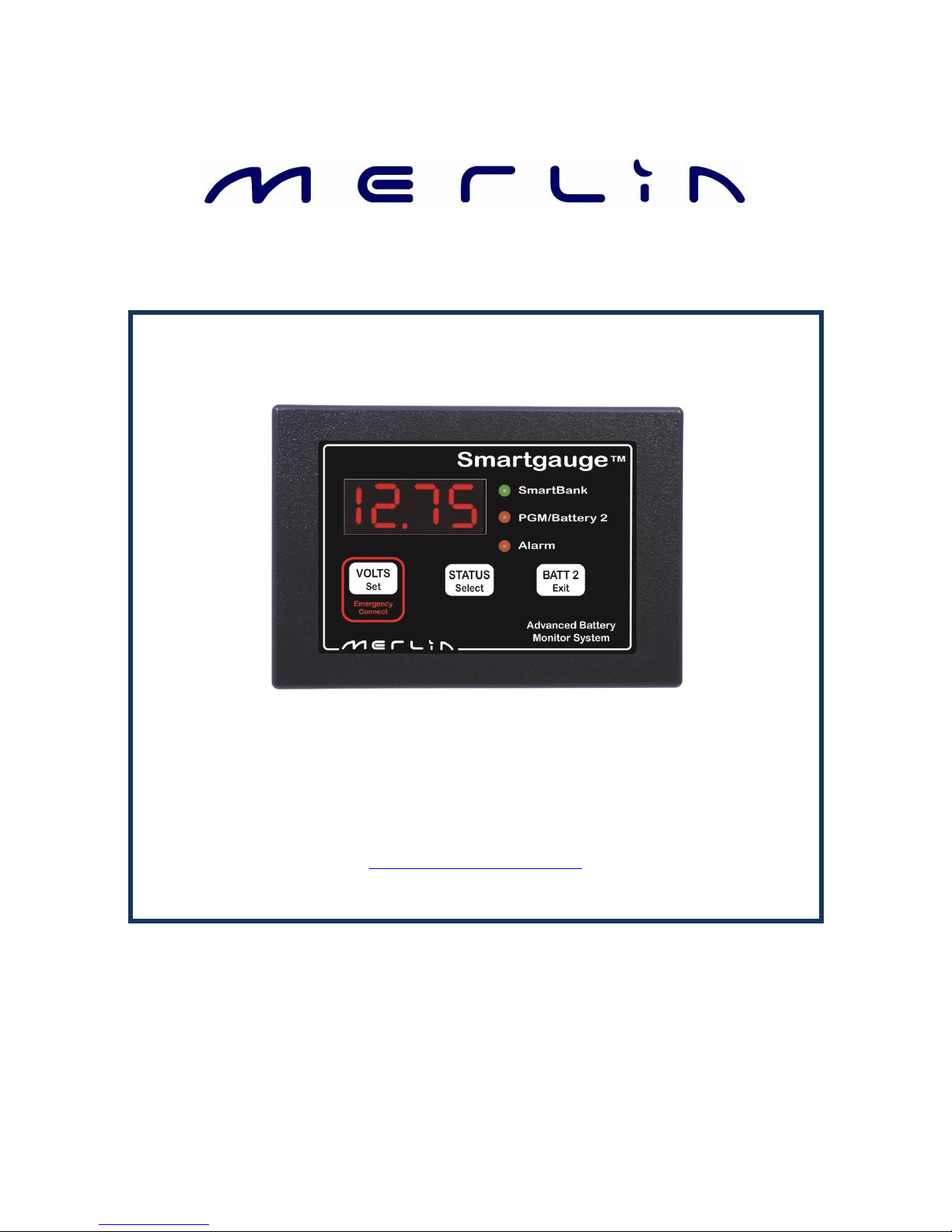
SmartGauge Installation and User Guide
Page 1
SmartGauge Installation and User Guide
Merlin Power Systems
Unit 4, Cabot Business Village
Holyrood Close
Poole, Dorset BH17 7BA
T: +44 (0) 1202 697979
F: +44 (0) 1202 691919
www.merlinpowersystems.com
Page 2

Merlin Power Systems version: 2.0.2
SmartGauge Installation and User Guide
Page 2
Merlin’s SmartGauge battery monitoring system is designed to provide highly accurate battery
voltage and SoC (State of Charge) information in a reliable, easy to use package.
Simple to install, the SmartGauge monitor provides much more accurate battery state information
than conventional “amp hour counters”, all without the need for installing additional shunts and
heavy cabling.
As the Merlin SmartGauge significantly differs from most battery monitoring equipment, please
take time to carefully read this manual in order to understand the correct method of installation
and user functions. Failure to do so may result in permanent damage to the SmartGauge and/or
other electrical systems.
Once the unit has been correctly installed, the benefits of acquiring the Merlin SmartGauge will
become fully evident.
If any questions arise after reading this manual, further technical support can be obtained from your
local dealer or Merlin Power Systems directly:
Europe: Tel: +44 (0) 1202 697979 North America: Tel: +1 (631) 594 5102
CONTENTS OF THIS GUIDE
1.0 Introduction Page 2
1.1 Main SmartGauge Features Page 3
1.2 Why SmartGauge? Page 3
1.3 Certificates of Conformity / Caution Notes Page 4
2.0 Quick Start Guide Page 5
3.0 SmartGauge Installation Basics Page 8
3.1 Important Installation Notes Page 8
3.2 Initial Start-Up Page 9
3.3 Battery Charge Status Page 9
3.4 Power Up after Power Loss Page 10
4.0 Basic Monitor Use Page 11
5.0 Set-Up Menu - Introduction Page 12
5.1 Set Up Menu – Battery Types Page 13
5.2 Set Up Menu – Charge Status Page 14
5.3 Set-Up Menu – Alarm Functions Page 14
5.4 Set-Up Menu – Primary Alarms Page 15
5.5 Set-Up Menu – Secondary Alarms Page 18
5.6 Set-Up Menu – Defeating Error Codes Page 19
5.7 Set-Up Menu – Displays Page 19
5.8 Set-Up Menu – Display Brightness Page 20
5.9 Set-Up Menu – Menu Lock Page 20
6.0 Error Codes Page 20
7.0 Reset to Factory Defaults Page 22
8.0 Alarm Outputs Page 22
9.0 SmartGauge in Conjunction with SmartBank Page 22
9.1 Warranty Page 23
10.0 SmartGauge Flowcharts Page 24/25
1.0 Introduction
Page 3

Merlin Power Systems version: 2.0.2
SmartGauge Installation and User Guide
Page 3
Monitoring and Display of Auxiliary Battery Voltage
Monitoring and Display of Auxiliary Battery State of Charge (SoC)
Monitoring and Display of Secondary Battery Voltage
User Defined High/Low Battery Voltage Alarms for Each Battery
User Defined High/Low SoC Alarm for Auxiliary Battery
Bright LED Daylight Display Screen
Volt Free Alarm Contact for Firing External Alarms, Relays etc
Conventional battery monitor systems count amp hours in/out of the batter to determine SoC. This
method is inherently inaccurate due to the SoC of the battery not necessarily being linked to the
amount of energy a battery can deliver. Factors such as temperature, battery charge/discharge rate,
incorrectly installed shunts and battery age all contribute to this inaccuracy. Unless the conventional
battery monitor is regularly reset (either automatically by fully charging the battery or manually), the
reading error will compound (known as synchronisation error).
For batteries being used in standby (nominal zero current) applications, Amp Hour counters will run
out of synchronisation as there are very low or no amps flowing through the shunt. Self discharge of
the batteries cannot be accounted for so, simply by just not using your electrical system, an amp
hour counter will display incorrect State of Charge Values.
SmartGauge uses just two wires to monitor the battery. Proprietary test methods are employed by
the SmartGauge to generate data. This data is then compared to detailed computerised battery
models. SmartGauge compares real world data with those models to generate SoC information. In
independent testing SmartGauge was found to be within 5% accuracy at all times.
Highly accurate SoC information not only allows you to confidently make decisions about how you
use your electrical system, it also allows you to automate certain functions like load shedding or
generator start/stop.
SmartGauge uses a self-correcting algorithm to determine battery SoC – over time it becomes more
and more accurate. This self-correction also means that SmartGauge automatically adjusts for
battery degradation over time. SmartGauge only needs 2-3 charge/discharge cycles to synchronize
with the batteries.
SmartGauge also interfaces with the Merlin SmartBank for highly advanced split charging – see
SmartBank manual for details.
1.1 Main SmartGauge Features
1.2 Why SmartGauge?
Page 4
Merlin Power Systems version: 2.0.2
SmartGauge Installation and User Guide
Page 4
Declaration of Conformity
Merlin Equipment Limited, Trading as Merlin Power Systems hereby declares that the product
marketed as SmartGauge is in compliance with the requirements of EU Electromagnetic
Compatibility (EMC) Directive 89/336/EEC.
SmartGauge complies with RoHS (Reduction of Hazardous Substances) Directive 2002/95/EC.
SmartGauge contains no Lead. At the end of life, SmartGauge should be disposed of as normal
electrical waste.
SmartGauge has been tested to and surpasses ISO-7637-2 for use on vehicles.
James Hortop
Managing Director
Merlin Power Systems UK
Date: 25
th
January 2013
CAUTIONS AND WARNINGS
CAUTION: Statements within this user guide identified with the word “CAUTION”, relate to practices
that may damage SmartGauge.
WARNING: Statements within this user guide identified with the word “WARNING”, relate to
practices that may cause injury or death.
This main SmartGauge user guide is written with the intention for use by qualified electrical
personnel. It does not identify normal practices or procedures that would indicate normal good
practice expected of a qualified electrical engineer. Please review with the specific professional
body or organization which covers your installation’s Health & Safety and Guidance regarding
good working practices.
1.3 Certificates of Conformity
Page 5
Merlin Power Systems version: 2.0.2
SmartGauge Installation and User Guide
Page 5
CAUTION & WARNING:
Batteries are hazardous
items. Please follow
battery manufacturer’s
recommendations for
health and safety. Use
only the appropriate tools
in conjunction with
manufacturer’s
instructions. Isolate both
battery and AC power
supplies before
attempting installation.
CAUTION & WARNING:
The Quick Start Guide
does not refer to each
and every Caution &
Warning Statement in this
manual. Be sure to
observe safe working
practices at all times.
Refer to the full manual if
you are unsure of any
practices that may
damage the SmartGauge
unit, your system wiring
or health.
This Quick Start guide assumes SmartGauge is being installed for
the first time. Following this guide will enable a first time user to
set up and start using SmartGauge basic functions. If more in depth
functionality is required, or the SmartGauge being used has been
connected to a battery before, please refer to the main sections of
this user guide.
CAUTION! As the Merlin SmartGauge significantly differs from most battery monitoring
equipment, it is highly recommended that the user carefully reads the main section of this user
guide in order to fully understand the correct method of installation and full range of user
functions. Failure to do so may result in permanent damage to the SmartGauge and/or other
electrical systems.
Once the unit has been correctly installed, the benefits of acquiring the Merlin SmartGauge will
become fully evident.
If any questions arise after reading the main section of the user guide, further technical support can
be obtained from your local dealer or Merlin Power Systems directly:
Europe: Tel: +44 (0) 1202 697979 North America: Tel: +1(631) 594 5102
2.0 Quick Start Guide
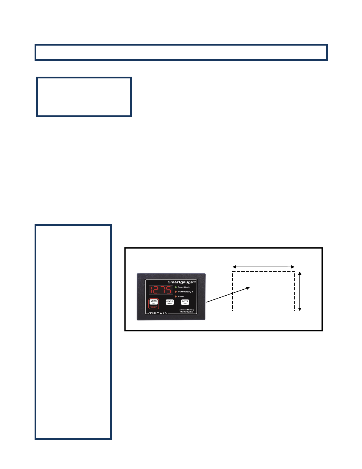
65.0mm
The SmartGauge display panel is typically mounted at the dash or navigation
area, or in other locations where it can be easily accessed for viewing. The
rectangular display panel requires a rough opening measuring 96.0mm wide
by 65.0mm tall, as illustrated in Figure 1 above. Access to the rear of the
monitor will be required to install ground and positive sense wires from the
monitor directly to the battery banks. In addition, there are terminals for
wiring connections to install separate wires for an audible or visual lowvoltage/low-battery capacity alarm.
Once a location has been determined for the monitor panel, sensing and
ground wires can be run to the batteries, as described in Figure 2 on the
following page.
Quick Start
Important Note:
96.0mm
Fig 1
65.0mm
Page 6
Merlin Power Systems version: 2.0.2
SmartGauge Installation and User Guide
Page 6
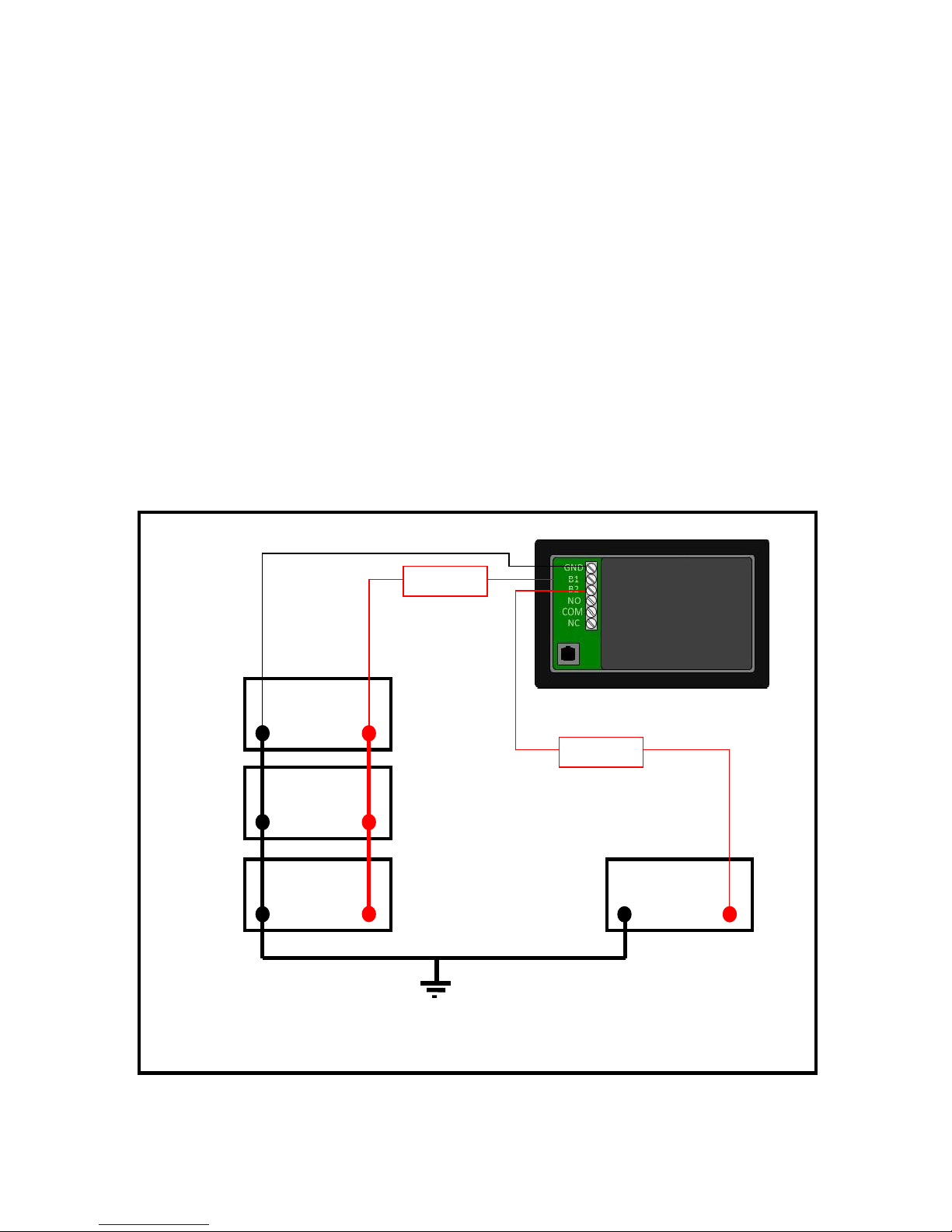
The SmartGauge does not require a separate shunt for installation. Battery voltage and state of
charge are both determined via sense wires connected directly to the terminals of one or both
battery banks. Referencing figure 2 below, to install:
1. An 18 gauge (AWG) ground wire from the GND terminal on back of the Smart-Gauge to the
battery negative post of the auxiliary battery bank.
2. An 18 gauge (AWG) positive sense wire from the B1 terminal on SmartGauge to the battery
positive post of the main battery bank. This wire must be fused at 3 amps with the fuse
holder installed as close to the battery as possible – note that the fuse should be outside any
battery compartment where battery gases may accumulate. It should not be run to busbars,
isolation switches, fuse panels etc.
3. If a second battery is to be monitored for voltage, run an additional 18 gauge (AWG) wire,
fused at 3 amps, from the B2 terminal on SmartGauge to the positive battery post of the
second battery bank or engine start bank. Again, this fuse should be located as close to the
battery as possible (but not inside the battery compartment if combustible gases can build
up).
AUX BATTERY
BANK
-VE
Rear View of SmartGauge
TO SYSTEM GROUND
-VE
-VE
-VE
3A FUSE
3A FUSE
+VE
+VE
+VE
+VE
ENGINE BATTERY
BANK
Fig 2
Page 7

Merlin Power Systems version: 2.0.2
SmartGauge Installation and User Guide
Page 7
Number Battery type
1 Deep cycle, wet cell, antimony lead acid
2 Gel Cell lead acid (a type of VRLA – Valve Regulated Lead Acid)
3 AGM – Absorbed Glass Matt (another type of VRLA)
4 Hybrid – calcium/antimony (usually marked as dual purpose or “leisure”) lead acid
5 Carbon Fibre lead acid
6 Maintenance free (wet cells but no way to top up the electrolyte) lead acid
Important Note on Type 3 -Use only for genuine AGM batteries.
Genuine AGM’s have the electrolyte held in a glass mat but with additional chemicals in the battery.
They require lower charge voltages and the off load terminal voltages will be similar to gel cells. Only
this type requires SmartGauge to be set to battery type 3.
There are other Glass Mat type batteries without the additional chemicals. This type usually has
charge voltages very similar to flooded wet cell batteries. The off load terminal voltages will also be
very similar to flooded wet cell batteries. If your AGM batteries are of this type then SmartGauge
should be set to battery type 1.
When the required battery type is in the display, press SET or EXIT. The display will now show
battery voltage, pressing Batt 2 will display the voltage on the second battery and the PGM/Batt 2
LED will be lit.
Pressing the Status button will display the charge status as a percentage from 0 to 100. This will
initially be showing 75% which may or may not be correct. If you know what the charge status of the
battery is you can manually set this to correspond with the batteries. Please refer to section 5.2 of
this user guide if this option is chosen.
Alternatively, if you are currently using the batteries (i.e. regularly discharging and charging them)
you may simply leave SmartGauge to synchronise itself. This will typically take 2 or 3 discharge and
recharge cycles. Synchronisation is not an instant effect. The SmartGauge will continue to track
battery condition with increasing accuracy over time.
This completes the quick start section of this user guide and initial setup of SmartGauge. For
operation and details of further functions and features, continue to refer to the remainder of this
manual.
After connecting as per Figure 2, the display will
briefly show the software and battery model
revisions. These are primarily for diagnostics and
can be ignored by the user.
SmartGauge will then show “bt 1” in the display and
the PGM/Batt 2 LED will be flashing. Use the
Status/Select button to scroll this value up to the
battery type that corresponds with the battery type
of the auxiliary battery bank according to the
following:-
Page 8

Merlin Power Systems version: 2.0.2
SmartGauge Installation and User Guide
Page 8
The information contained herein relating to installation is for guidance only. It is believed to be
correct at the time of writing. It is the installer’s responsibility to ensure compliance with any relevant
safety regulations, codes of practice, legal requirements etc. The manufacturers, suppliers, dealers
and/or their agents cannot be held responsible for any breach of such requirements as a result of any
information contained herein. Installation of SmartGauge implies acceptance of these terms.
The purpose of this manual is to enable the installer to install SmartGauge in a manner that permits
it to operate as designed. This manual’s purpose is not to educate the installer on the legal
requirements of any particular type of installation. The manufacturer, supplier, dealer and/or their
agents cannot know what the final installation will be and therefore cannot know what the legal
requirements of such installation may be.
Installation of SmartGauge is simple and should be completed in a short time. Only two connections
are required to operate SmartGauge for monitoring a single battery bank system, with only three
wires required for a dual-bank installation.
1. B1 = Battery 1 – this must be the primary auxiliary battery bank being monitored. B2 = secondary
auxiliary bank OR engine start battery.
2. Battery 1 and Battery 2 must both be the same nominal voltage, either both 12 volts, or both 24
volts. SmartGauge cannot be used on a mixed installation of both 12 and 24 volt supplies together.
3. Battery 1 and Battery 2 must share a common negative. It is not possible to install SmartGauge on
two isolated battery systems or on two-battery systems with a common positive.
4. Keep the wires running from the batteries to the SmartGauge as short as possible. Use 18-gauge
(AWG) wire for all connections.
5. In order to comply with most safety regulations and standard good practice, a fuse rated at 3
amps should be fitted in the positive wire as close to the battery as practical but not inside the
battery compartment unless the batteries are certified as safe for use in habitable or sealed
compartments (i.e. usually Gel cells or AGMs) or unless the batteries are externally vented via their
own ventilation system.
6. The SmartGauge battery +ve and –ve must always be connected directly to the battery posts.
Never connect to bus bars, distribution panels, fuse panels or isolation switches. Incorrect
SmartGauge connection will result in false battery monitoring.
7. Never power other loads from the SmartGauge battery sensing cables. If a SmartGauge alarm
function is being used to power a buzzer or lamp for instance, then the alarm equipment must have
its own power feed.
8. If SmartGauge is being installed in an installation with an existing ammeter or amp hour counter
utilising a shunt, then it is normal practice to connect all equipment to the load side of the shunt, not
to the battery side. Leave all other equipment connected in this fashion, but the SmartGauge must
be connected directly to the battery terminals in order to function correctly (the resistance in the
shunt will alter the accuracy of SmartGauge) . The SmartGauge current drain is so low, it will have no
effect on existing ammeter readings.
3.0 SmartGauge Installation Basics
3.1 Important Installation Notes – please read carefully
Page 9

Merlin Power Systems version: 2.0.2
SmartGauge Installation and User Guide
Page 9
The following initial start-up sequence is relevant only the first time the product is powered up from
new. SmartGauge retains memory information even without power. It automatically detects if it has
been previously connected to a battery. If this is the case, please refer to the start-up sequence
following power loss, covered in section 3.4 of this manual.
On powering up SmartGauge for the first time, software revision information is briefly displayed.
This is for manufacturer reference only and can be ignored by the user.
SmartGauge will then display “SC” whilst it performs a System Check of the system battery voltage.
SmartGauge will then display “SC12” or “SC24” indicating that it has detected either a 12 or 24 volt
system. A chart at the end of this manual shows details of the expected display during a first time
power up.
Finally it will display “bt 1” and this is your opportunity to select the battery type. Refer to section
5.1 headed “Set-Up Menu - Battery type” for a list and explanation of battery types. Pressing the
Status button will scroll through the available battery types. Pressing the Volts button will select and
store the currently displayed battery type, the display will flash 4 times to signify the data has been
written to computer memory. The current battery voltage will then be displayed.
This completes the installation and initial start-up.
After SmartGauge has completed its initial start-up and self-check procedures, the charge status of
the primary battery bank can be displayed by pressing the STATUS button. The State of Charge or
SoC is shown as a percentage. By default on initial start-up the SoC will be shown as “C075”
indicating a charge state of 75%. This is unlikely to represent the true SoC of the battery bank being
monitored at this time, but as the batteries are used i.e. discharged and charged through normal
use, SmartGauge will “learn” the actual SoC, becoming ever-more accurate as each cycle passes.
There is also an option to manually enter the State of Charge at this point if it is known.
Refer to the section 5.2 “Set-up menu – Charge Status” for methods of determining and manually
entering the SoC.
3.2 Initial Start-Up
3.3 Battery Charge Status
To revert back to displaying the battery
voltage press the VOLTS button.
If SmartGauge is connected to a two
battery bank system, the voltage on the
second battery bank (or engine start
battery) can be displayed by pressing the
BATT 2 button. The PGM/Batt 2 indicator
lamp will be lit whenever voltage of the
engine start battery bank is being
displayed.
To revert to displaying the voltage or SoC
of the primary battery bank, press VOLTS
or STATUS buttons respectively.
Page 10

Merlin Power Systems version: 2.0.2
SmartGauge Installation and User Guide
Page 10
SmartGauge must be permanently connected to the battery terminals of the battery bank being
monitored in order to operate. It cannot operate and accurately track the State of Charge of the
batteries if its power feed is not permanent. In the event of power failure or interruption, the
SmartGauge will retain most settings in memory. On re-application of power, the unit it will continue
to operate as before except for the following:
2. Charge Status will not initially be accurate. It will probably be necessary to revert to one of the
four methods described in section 5.2 “Set-Up Menu – Charge Status” to re-calibrate this
function. However, if the batteries have been through 2 -3 discharge/charge cycles since the
power interruption, SmartGauge will have already re-synchronized itself.
3. If Primary alarms were set to operate on low charge status, then the alarm will have been
disabled. Low or high voltage alarms will remain active. All the set points such as voltage or
status activate and deactivate levels, low status timer etc. will remain as they were, but an
actual low status alarm will be switched off. Secondary alarms will remain as they were set prior
to the power failure (alarm functionality is explained later in this manual).
There is no need to reset any other functions. SmartGauge will remember all settings. If necessary,
refer to the flow chart headed “Re-power up following power failure” at the end of this manual for
details of the expected display.
Note that re-powering up SmartGauge results in different displays than the initial power-up (or
following a reset to factory defaults). There is now no System Check (“SC”) and the unit does not ask
for the battery type. Both these parameters will have been retained in memory from previous use.
If there is a requirement to revert the unit to “as new” status, (perhaps the unit is being moved to a
new installation, for instance), then refer to section XXX “Reset to factory defaults”.
3.4 Power-Up Following Power Loss
1. The display will alternate between “VOLTS” and
“E 01” (error 01 – lost power) until a key is
pressed. This is to alert the user to the fact that
power has been lost. E 01 will continue to flash
until a button is pressed, if another error occurs
the new error will not take over, E 01 will remain
as the priority error. If the display goes into
sleep mode (a simple power saving feature
described later in this manual), the ”E 01” code
will still continue to flash.
Once a button is pressed the display will move
on to show a figure – for example, 2.36 or 17.49
This is the approximate time in hours and
minutes since power was re-applied. It will count
up to a maximum of 99 hours and 59 minutes
and will then remain at that display. This time
display may help the user decide if Charge Status
re-calibration is necessary.
Page 11

Merlin Power Systems version: 2.0.2
SmartGauge Installation and User Guide
Page 11
If the battery voltage goes outside the measurement range (9 to 17 volts for 12 volt systems, 18 to
34 volts for 24 volt systems), the volts display will show “HI” or “LO” while the voltage remains
outside the range. An “E 04” error will also be displayed and will remain displayed, to alert the user
to a problem, until any button is pressed. If the battery voltage remains below the low voltage
warning for the set battery type an “E 02” error will be displayed. If the battery voltage remains
above the high voltage warning for the set battery type an “E 03” error will be displayed.
These high and low voltage warnings should be responded to immediately as battery damage may
occur or other dangerous conditions may arise such as the production of explosive gasses. If power
is lost an “E 01” error will be displayed.
“HI” and “LO” error displays are only shown if the display is currently set to “Volts”. They are not
displayed if the display is set to “Status”. They are also not shown if the display has gone into sleep
mode. But the resulting “E 0x” error will remain displayed. In fact, all error codes are displayed
regardless of sleep mode.
4.0 Basic Monitor Use
Pressing the VOLTS button will display volts on
the primary auxiliary battery bank. Pressing the
STATUS button will display charge status of
that same bank. Pressing the BATT 2 button
will show the voltage on the secondary or
engine start battery bank and the PGM/Batt 2
LED will light up to indicate the engine battery
voltage is currently being displayed. To return
to the primary bank, press VOLTS or STATUS.
If the SmartGauge unit is left alone for 2
minutes, it will go into sleep mode. This is a
power saving feature. SmartGauge will
continue to operate, calculating the charge
status and monitoring for error conditions,
alarms etc. Pressing any button will bring
SmartGauge out of sleep mode and the display
will operate for a further 2 minutes. Sleep
mode may be defeated if required (refer to the
“Set up Menu - Display Modes”), later in this
user guide.
Page 12

Merlin Power Systems version: 2.0.2
SmartGauge Installation and User Guide
Page 12
The SmartGauge “Set-Up Menu” allows the user to program and adjust many of the monitor’s
features. Each parameter is covered in sub-sections hereafter in section 5.x of this user manual.
When in the set-up menu, the PGM/Batt 2 LED will flash. All battery monitoring ceases while the
SmartGauge is in Set-Up Mode. For this reason, the user gets 2 minutes to set-up each parameter. If
the two minutes is exceeded, the current selection in the display window is written to SmartGauge
memory, and the unit reverts back to monitoring the batteries.
When in the Set-Up Menu, the main legends on the control buttons are no longer active. The
buttons assume the role of the secondary legends on each button (in smaller characters below the
main legends).
Pressing the SELECT button will scroll through all available selections offered in that menu. Pressing
the SET button will select the currently displayed option. The display will flash 4 times to indicate
this option has been successfully selected and will be written to the SmartGauge memory.
The Set-Up Menu will then move on to the next menu item.
At any time when moving onto the next menu item, the currently selected option will be displayed
first without ever changing any of them. This allows you to look through the menu to check all the
settings without changing any of them.
Pressing the EXIT button does the same as the SET button, except after writing the currently
displayed option to SmartGauge memory, the Set-Up Menu will be exited without moving onto the
next menu item, and battery monitoring will re-commence.
5.0 Set-Up Menu - Introduction
To enter the set-up menu press both the Volts and
Status buttons simultaneously and keep them
pressed. After 2 seconds the display will change. If a
SmartBank split charge system is not installed in
conjunction with SmartGauge, the display will
automatically enter the set-up menu and “BT X” will
be displayed.
If a SmartBank is installed the display will first show
“SU 1” (Set-up menu 1). By pressing VOLTS at this
time “SU 1” will be selected (the SmartGauge set-up
menu) and “BT X” will be displayed.
In either case, once “BT X” is visible, the monitor is
now in “Set-Up Mode – Battery Type”
Refer to section 5.1 for further instruction.
Page 13

Merlin Power Systems version: 2.0.2
SmartGauge Installation and User Guide
Page 13
Once the Set-Up Menu is entered, the first item to be set is the battery type, shown as “BT X” where
“BT” signifies battery type and “X” shows the current selected type. If this is a first power up, “X” the
display will show “1”. Otherwise, it will show the battery type currently stored in SmartGauge
memory.
If you are unable to identify the battery type, please contact your Battery Supplier or SmartGuage
dealer for advice.
The battery types are numbered 1 to 7 and are as follows:-
Type 1 Standard wet cell deep cycle Lead Acid - also known as Antimony/Antimony
Use this setting for Standard vented Lead Acid deep cycle batteries or,
Lead acid recombinant (have a catalyser in the cap to recombine the oxygen and hydrogen back into
water that is normally lost during charging in a standard Lead Acid battery) do not confuse with
VRLA (AGM or Gel).
Type 2 Gel Cell
Use this setting only for Gel Cells
Type 3 AGM - Absorbed Glass Mat (VRLA)
Use only for genuine AGM batteries.
The genuine AGM’s have the electrolyte held in a glass mat but with additional chemicals in the
battery. They require lower charge voltages and the off load terminal voltages will be similar to gel
cells. Only this type requires SmartGauge to be set to battery type 3.
Note : There are other Glass Mat type batteries without the additional chemicals. This type usually
has charge voltages very similar to flooded wet cell batteries. The off load terminal voltages will also
be very similar to flooded wet cell batteries. If your AGM batteries are of this type then SmartGauge
should be set to battery type 1.
Type 4 HYBRID - Also known as Antimony/Calcium or Hi-Calcium.
Usually identified by being sealed but the acid inside the battery is still liquid. Many are fitted with a
‘magic eye’ to give an approximate indication of battery condition. Usually marked maintenance free
and its normally not possible to open the top of the battery.
Type 5 Carbon Fibre
Lead/Acid batteries with Carbon Fibre additives to the plates.
Type 6 Maintenance free, Calcium/Calcium.
Marketed as a semi-traction battery.
Type 7 Custom Program
Do not select type 7 unless your SmartGauge has been supplied with a specific battery program.
Type 7 only appears on the set-up menu after the initial power up sequence.
5.1 Set-Up Menu – Battery Type
Page 14

Merlin Power Systems version: 2.0.2
SmartGauge Installation and User Guide
Page 14
1. If you know what the state of charge is (for instance you
may know the batteries to be fully charged) you can enter
the set-up menu and manually set the charge status (refer to
this section of the user guide below).
2. Charge or discharge the batteries to approach 75%. When
the actual state of charge of the batteries meets the default
display of 75%, SmartGauge will be in perfect synchronisation
with the batteries and will track the charge status from that
time onwards.
3. Leave SmartGauge working for 48 hours. Use the battery
system as usual, SmartGauge will self-calibrate over the next
2-3 charge and discharge cycles of the battery bank. Unlike all
other battery state of charge meters currently available,
SmartGauge becomes more accurate the longer it is used. All
other battery state of charge meters become less accurate
the longer they are used and require ever more frequent recalibration.
On initial set-up, SmartGauge defaults to a charge status of 75%. This is highly unlikely to match the
actual charge status of the batteries being monitored.
There are 4 simple ways in which this can be corrected:
4. Switch on a charging device and wait until you know the batteries are fully charged (by the
charger switching into float charge mode). Enter the set-up menu and manually set the charge status
to 100%.
Charge Status can be manually set to any value between 0 and 100%. While in the Set-Up Menu,
press the Set key a number of times until “Cxxx” is displayed. “C” signifies Charge status and “xxx”
the % value. Pressing the Select button will scroll up from 0 to 100% .When the desired value is
displayed, press the SET key. The display will flash 4 times to show the value has been stored. The
display will then move onto the next menu item.
Alternatively, pressing the Exit button will write the value to memory then exit the set-up menu.
There are two types of alarm incorporated in SmartGauge, the Primary Alarm and the Secondary
Alarm. They both operate on the same hardware output but are designed for different purposes.
The first is the Primary Alarm which can be set OFF or set to operate on a user programmable
low/high voltage or to operate on one of two types of user programmable low charge status.
5.2 Set-Up Menu – Charge Status
5.3 Set-Up Menu – Alarm Functions
Page 15

Merlin Power Systems version: 2.0.2
SmartGauge Installation and User Guide
Page 15
Set-up mode – Uoltage (Voltage) Alarm:
If a low voltage alarm was set, the lower voltage trip point is the voltage below which the actual
battery voltage will have to fall in order to trigger (activate) the alarm output. This is the activation
voltage. The factory default for this value is 11.80 volts. Pressing the SELECT button will scroll this
value up to and including 16.50 volts. It will then cycle to 10.50 volts, then continue to scroll
upwards. When the desired value is displayed, press the SET button to write the value to memory,
the display will flash. The upper voltage trip point is the voltage which the actual battery voltage will
have to rise to in order to deactivate the alarm. This is the deactivation voltage. The factory default
for this is 13.20 volts. Pressing the Select button will scroll this value up to 16.50 volts, it will then
wrap round to whatever value was previously entered for the alarm activation voltage. This means
that no matter what one does, SmartGauge will not allow this value to be set lower than the
activation voltage. Pressing the SET button will write the value to memory.
On entering this section of the set-up menu, the display will show “PA
x”. PA signifying Primary Alarm. “x” displaying either “O” “ U” “ S”. or
“t”. “O” means alarms are switched Off.
“U” means Uoltage (Voltage) alarm is enabled
“S” means low Status alarm is enabled.
“t” means a timed low status alarm is enabled.
“U”, “S” and “t” type alarms are more fully described under their
respective headings below.
The SELECT button will scroll round them.
The SET button will set the desired alarm. The display will flash
showing the value was written to memory. Changing the alarm type
will cancel any currently active alarms and reset the timed alarm
timers to the user’s programmed default value.
On selecting “PA O” the display will flash and then move onto the
next item in the set-up menu.
1. On selecting “PA U” the display will flash to show
the value was written to memory.
The display will then show either “Hi” or “Lo”. The
SELECT button will alternate between these two
options. “Hi” sets a high-voltage alarm. “Lo” sets a
low-voltage alarm. Pressing SET will store the value.
2. The display will then show “XX.XX” which is the
lower voltage trip point. Once this is set (using the
SELECT and SET buttons) the display will again show
“XX.XX” which is the upper voltage trip point.
5.4 Set-Up Menu – Primary Alarms
Page 16

Merlin Power Systems version: 2.0.2
SmartGauge Installation and User Guide
Page 16
Clarification –
For a low voltage alarm:
1. The battery voltage has to fall below the activation voltage to trigger the alarm.
2. The battery voltage has to rise to the deactivation voltage to kill the alarm.
For a high voltage alarm:-
1. The battery voltage has to rise to the deactivation voltage to trigger the alarm.
2. The battery voltage has to fall below the activation voltage to kill the alarm.
Set-up mode – Low Status Alarm:
There are two types of Low-Status alarm. The first is exactly the same as the low-voltage alarm but
operates on charge status instead of on battery voltage. So the alarm will activate once the charge
status falls below the chosen activation status, and will deactivate after the charge status rises back
up to the chosen deactivation status. This type is designated in the display as “PA S”
Set-up mode – Timed Low Status Alarm:
The second type of status alarm is the “PA T” (Timed Low Status Alarm)
If this alarm is set, the alarm will trigger (be activated) once the charge status falls below the
activation status. The alarm will remain triggered until the status rises back up to the same
activation level but then, once this happens, a timer is started which counts down from the set time
period, and when it reaches zero, the alarm is deactivated. The main reason for this type of alarm is
to enable an auto start generator set to be started once the charge status falls to a certain level and
then run for a certain fixed period.
If a high voltage alarm was set then the procedure remains
identical except the upper voltage trip point is the voltage which
the battery voltage will have to rise to in order to activate the
alarm. Once the alarm is triggered, the battery voltage will have
to fall back down below the lower voltage trip point in order to
deactivate the alarm.
The display will then move on to the next item in the set-up
menu. At any time in the set-up menu, pressing the Exit button
will write the current value to memory then exit the set-up
menu.
The “PA S” type alarm is set in exactly the same way as
the “PA U” alarm except “PA S” is selected instead of
“PAU”. i.e. the activation status will be set, followed by
the deactivation status.
Clarification:
1. The charge status has to fall below the activation
status to trigger the alarm.
2. The charge status has to rise to the deactivation
status to kill the alarm.
The range limits are:
1. Activation status = 1 to 75%
2. Deactivation status = activation status to 100%
Page 17
Merlin Power Systems version: 2.0.2
SmartGauge Installation and User Guide
Page 17
The normal full time for a timed alarm run will not be changed and will remain as you last set it (or at
the factory default if no changes have been made). It is not possible to change the default run time
whilst a timed alarm run is active. Note that this timed period is approximate. The timed period and
the display will be accurate to within about 10%. Also, note that internally SmartGauge counts in
seconds whereas the display only shows the minutes.
It is rounded to the nearest minute so when the display counts down and reaches zero, there could
in fact be 30 seconds remaining.
On selecting “PA T” the display will flash to show this
selection was written to memory. The display will then
show “xx” which is the charge status below which the
actual battery charge status will have to fall in order to
trigger (activate) the alarm output. This is the
activation status. The factory default for this value is
50%.
Pressing the SELECT button will scroll this value up to
and including 75%. It will then cycle to 1 and continue
to scroll upwards.
When the desired value is displayed, press the SET
button to write the value to memory, the display will
flash as usual. The activation value is now set. Note
that this value shares the same memory as that used
for the normal low status alarm. So changing one, will
change the other.
The display will now show “tx.xx”, indicating the time,
in hours and minutes, that the alarm will remain
activated. The default is 4 hours. However, if an alarm
of this type is actually active when you enter the set-up
menu (i.e. the alarm LED is on), then this figure will be
the current time remaining, on the current countdown
timer, rounded to the nearest 15 minutes. This enables
the user to increase or decrease the remaining time for
an existing alarm timer run.
Pressing the SELECT button will increase this time in
steps of 15 minutes up to a maximum of 9 hours and 45
minutes at which point the display will wrap round to
15 minutes then continue cycle up.
Once the desired time is reached, pressing the SET
button will, as usual, cause the display to flash, the
value will be written to memory and the display will
move on to the next item in the set-up menu.
If an alarm is not active at the time you enter the set-up
menu then this time period will become the default
time period for all future timed status alarms.
Remember, changing the alarm type will cancel any
currently active alarms. Be aware that if this menu item
is entered while a timed alarm run is active, and it
therefore shows the time remaining on the current run
(as opposed to your default run time), then only the
time remaining on the current run will be affected.
Page 18

Merlin Power Systems version: 2.0.2
SmartGauge Installation and User Guide
Page 18
Primary Alarms – General
Once an alarm is triggered, the alarm output will activate. The Alarm LED on the front panel will
illuminate and the display will alternate between its current display (for 3 seconds) and the alarm
display (for 1 second). The alarm display will show :
“A LU” - for Alarm Low Voltage
“A HU” - for Alarm High Voltage
“A LS” - for Alarm Low Status
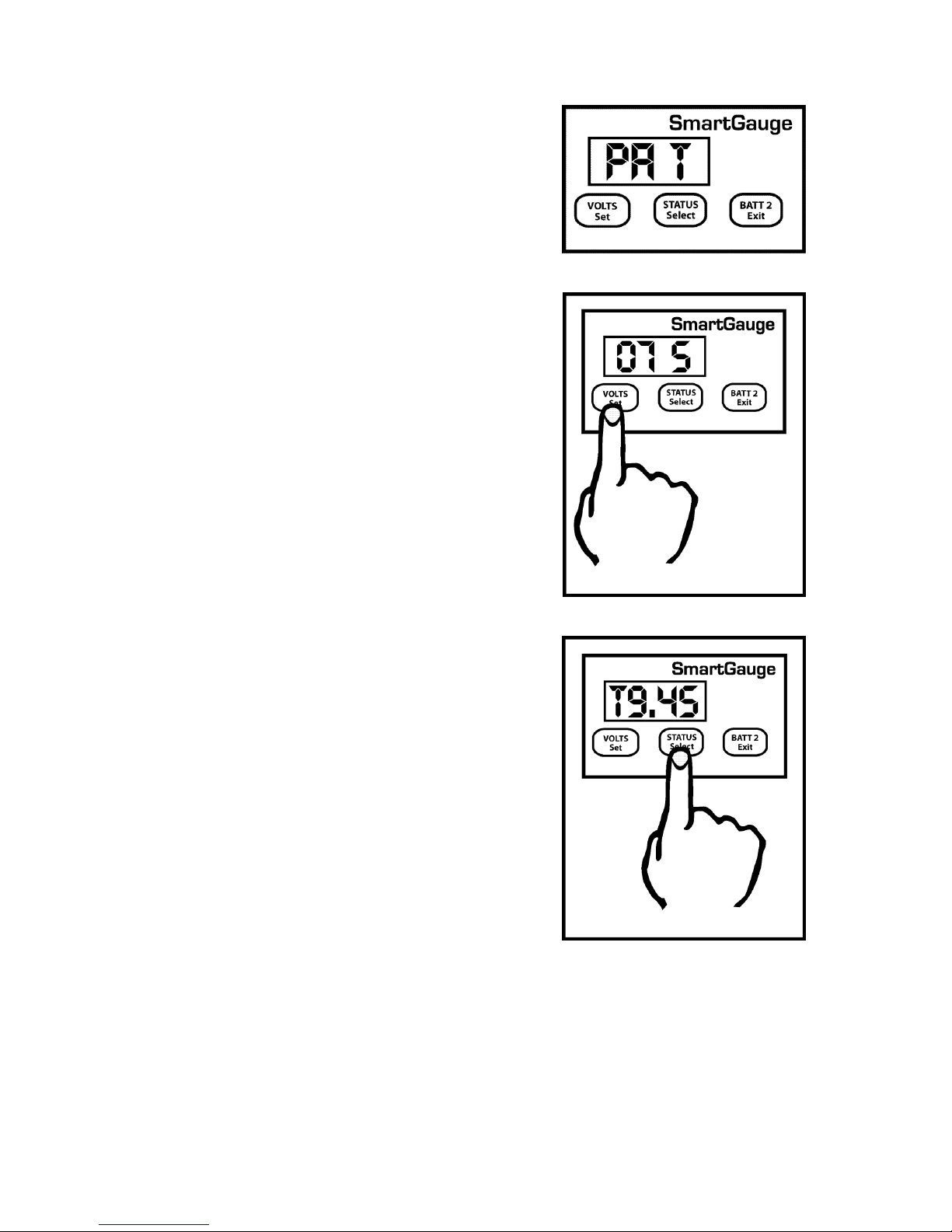
If “PA t” has been set, then when the alarm triggers, the display will alternate in 2 ways. It will show
the current display (3 seconds), then it will show “A Lt” (Alarm Low status timed),(1 second), it will
then revert to the normal display (3 seconds), it will then show the time in hours and minutes until
the alarm is due to deactivate (for 1 second). For example for a time of 9 hours 45 minutes, the
display would show “t9.45”.
Changing the alarm type will cancel any currently active alarms. Alarm set points and timers can be
changed, and the existing alarm will remain active. But actually changing the alarm type (such as
from low voltage to low status) will cancel the currently active alarm. This is a simple way of
cancelling an active alarm. If the display is in sleep mode then the alarm output will still activate but
the alarm status display will not show, however the Alarm LED on the front panel will still light up.
Pressing either button will show what type of alarm has activated in case you forget which type you
set. And in the case of “PA t” will show the time remaining before deactivation.
The purpose of the secondary alarm is to activate an external alarm output, perhaps to sound an
audible warning device or warning light in the event of SmartGauge generating one of its several
error codes.
The display will show “SA x”, “SA” signifying Secondary Alarm and “x” showing the current setting.
The default is “O”, Off. “x” can be set to any of the following:-
O Off Default - Error codes will never activate the alarm output.
U Uoltage - Error codes E 02 and E 03 (low or high voltage warnings for selected battery type) will
activate the alarm output.
r range - Error code E 04 (measurement range error) will activate the alarm output.
P Power lost - Error code E 01 (Power lost) will activate the alarm output.
A All – All Error codes will activate the alarm output.
S SmartBank This option only appears in the set-up menu if a SmartBank is installed in conjunction
with SmartGauge. This option allows the Secondary Alarm to be triggered by SmartBank errors.
Secondary Alarms and Primary Alarms operate independently of each other. They may both be set at
the same time. Adjusting or defeating one will not affect the other. But note that there is only one
hardware output.
5.5 Set-Up Menu – Secondary Alarms
Page 19

Merlin Power Systems version: 2.0.2
SmartGauge Installation and User Guide
Page 19
In some circumstances, especially during battery charging, it may be necessary to defeat the error
code functions in SmartGauge. Certain constant voltage chargers have a very high charge voltage
delivered for short periods. This high charge voltage can trigger repetitive SmartGauge error code
E 03.
If the “Secondary Alarm” function has been set to activate the alarm on E 02 or E 03, or set to
activate the alarm on all error codes, and E 02 and E 03 have been disabled then they will no longer
trigger the alarm. The remaining error codes will still activate the alarm as programmed.
In the Set-Up Menu the display will show “EC x” signifying Error Codes and “x” being either “1” for
error codes enabled (the default) or “O” for error codes disabled. Use the buttons as before to select
either “1” or “O”. Note that this setting only affects error codes E 02 and E 03. The other error codes
will continue to operate and trigger alarms accordingly.
There are three display modes available in SmartGauge. The modes apply whether the display is
showing volts or charge status.
The default factory setting displays for 2 minutes then goes into sleep mode. This mode is signified in
the setup menu as “dt t” meaning display type = timed. This display will remain active for 2 minutes
following a button press. It will then go back to sleep. Pressing a button will switch the display back
on for another 2 minutes.
The second display mode is “dt A” meaning “display type = Always” where the display will always be
on and will never go into sleep mode.
The third display mode is “dt U” meaning “display type = Voltage” where the display will go into
sleep mode, after 2 minutes, as usual, below a certain voltage but will always remain on above a
certain voltage. This voltage is actually the upper voltage trip point for the high/low voltage alarm.
The factory default setting for this is 13.20 volts (26.40 volts on 24 volt systems). So if this display
mode (“dt U”) is selected and the alarm factory defaults have not been adjusted, the display will
blank as normal after 2 minutes if the battery voltage is below this level but will always be on above
this voltage. This makes sense in so far as if the battery voltage is above this level then clearly the
batteries are either being charged or they are well charged and in either case the extra few
milliamps of power consumed is not an issue. It also allows a keen eye to keep watch on the battery
charge voltage without having to continually press buttons. But when the charger is switched off
SmartGauge will revert to the minimum required current draw by blanking the display 2 minutes
later.
Note that whilst this setting uses the upper deactivation voltage level of the low voltage alarm, the
low voltage alarm does not have to be enabled or active for this function to operate. The two
functions merely share the same value.
To select the display mode, enter the set-up menu as usual, then press the VOLTS button until “dt x”
is displayed. “dt” signifying display type, the x showing either t, A or U. Now press the STATUS
button to scroll through the three or four values. Press VOLTS to confirm the choice. The display will
flash to show the value has been written to memory. The display will then move onto the next menu
item.
5.6 Set-Up Menu – Defeating Error Codes
5.7 Set-Up Menu – Displays
Page 20

Merlin Power Systems version: 2.0.2
SmartGauge Installation and User Guide
Page 20
The display brightness is fully adjustable to enable the SmartGauge to be used in any light
conditions. One of the advantages of this type of display (LED – Light Emitting Diode) as opposed to
the other common display (LCD – Liquid Crystal Display) is that they can be read in zero light
conditions as well as daylight.
To adjust the display brightness enter the set-up menu, then press the SET key until “db x” is
displayed. “db” signifies display brightness, x indicates the current brightness which will be from 1 to
8. The factory default value is 4. Pressing the SELECT button will scroll through the values, cycling to
1 when 8 is reached. You will see the brightness change as you scroll through the values. When you
find the brightness level that best suits your environment, press the SET button. The display will flash
to show the value has been stored then SmartGauge will move on to the final item in the set-up
menu.
The last item in the set-up menu will display “Loc0”. This allows access to the set-up menu to be
denied.
Pressing STATUS will alternate between “Loc0” (meaning lock is disabled) and “Loc1” (meaning lock
is enabled).
Setting “Loc0” will allow SmartGauge to continue to operate exactly as before. Setting “Loc1” will
prevent future access to the set-up menu. All other functions of SmartGauge remain identical. If
“Loc1” is set, then any future attempts to enter the set-up menu will be completely ignored. In order
to unlock SmartGauge it will be necessary to attempt to perform a “reset to factory defaults”.
If the lock is disabled (Loc0), then “reset to factory defaults” will operate as usual. If the lock is
enabled (Loc1) then when attempting to perform a “reset to factory defaults”, it will not be allowed.
It will simply unlock the unit to once again, allow access to the set-up menu.
Error codes do not indicate a problem with SmartGauge. They indicate a problem with the
installation or other equipment such as chargers. For instance, a continual “E03” error signifies a
charger fault, not a SmartGauge fault.
With all “Exx” type error codes, the code is displayed alternately with the current display. If the
display has gone into sleep mode, the error code will still be displayed. This is to ensure that an error
does not go unnoticed simply because the display was asleep.
The error code will continue to be displayed after the fault condition that caused the error has
cleared.
In order to clear the error code, simply press any button.
If, whilst an error code is displayed, another error occurs, the new error code will take precedence.
The old error code will be lost. That is to say, only one error code will ever be displayed. The
exception to this is the unique case of an “E01” (lost power) error. This error takes precedence over
all other errors.
5.8 Set-Up Menu – Display Brightness
5.9 Set-Up Menu – Menu Lock
6.0 Error Codes
Page 21

Merlin Power Systems version: 2.0.2
SmartGauge Installation and User Guide
Page 21
“E01” – Power was lost and reapplied.
If power to SmartGauge is lost, when it is reapplied SmartGauge has no way of knowing how long
power was lost or know what has happened to the batteries in the meantime. Therefore “E01”
means that the charge status will probably be incorrect. It also means that any primary status alarms
will have been disabled. Alarm set points will still be as they were last set but the actual alarm will be
switched off and will remain so until re enabled by the user. Any low voltage alarms or secondary
alarms will remain set as they were prior to the power loss.
Pressing any button will clear the “E01” error code. The display will then show the time in hours and
minutes since power was reapplied (up to a maximum of 99 hours, 59 minutes). Pressing any button
will clear this display. If no button is pressed, the display will time out after 2 minutes then revert to
normal operation. While showing the time since re-power, the PGM LED will flash.
“E02” – Battery voltage has been below acceptable level for battery type.
Each different battery type has certain voltage and time limits, which, if exceeded, may damage the
batteries.
For instance if a deep-cycle lead acid battery experiences a terminal voltage lower than 10.2 volts for
any appreciable length of time it may cause serious, immediate, permanent damage to the battery.
SmartGauge has different voltage and time limits for each battery type. If this limit is exceeded then
SmartGauge will generate an “E02” error. This error will alert the user to the problem. Be aware that
if this error code occurs it is an indication of a severe problem in the installation that, if allowed to
persist, will eventually destroy the batteries. It is not an indication of a problem in SmartGauge.
Note that this error means the voltage and time limits have been exceeded since a button was last
pressed. It does not mean they are currently being exceeded. The error is stored after the fault has
cleared until the error is cleared by pressing a button.
“E03” – Battery voltage has been above acceptable level for battery type.
This is similar to “E02” but for high voltage. The voltage level and time limits vary dependent upon
the battery type selected.
“E04” – Battery voltage has exceeded the measurement range of SmartGauge.
SmartGauge can accurately measure voltages between 9.00 and 17.00 volts in 12 volt mode and
between 18.00 and 34.00 volts in 24 volt mode.
If these limits are exceeded SmartGauge has no way of measuring what the actual voltage is. Also, if
these limits are exceeded there is something seriously wrong with the installation. Such extreme
voltages simply should not arise and indicates a serious problem with the charging system.
• HI Battery voltage is above upper measurement limit of 17.00 volts (34.00 volts in 24 volt
• installations)
• LO Battery voltage is below lower measurement limit of 9.00 volts (18.00 volts in 24 volt
• installations)
Note that Hi and LO errors will clear as soon as the voltage returns to within the measurement
range. They will, however, leave an “E04” error code on the display.
Page 22

Merlin Power Systems version: 2.0.2
SmartGauge Installation and User Guide
Page 22
Circumstances such as change of battery technology, or the need to override a menu lock, require
that the SmartGauge is returned to its Factory Default state. To return the monitor to its default
settings:
1. Disconnect the power feed to SmartGauge (pull the fuses in each feed wire out).
2. Press both the VOLTS and STATUS buttons and keep them pressed.
3. Reapply power, still keeping the buttons pressed.
4. SmartGauge will display the software revision as usual. Keep the buttons pressed.
5. SmartGauge will display the battery model revision as usual. Keep the buttons pressed.
6. The display will go blank.
7. Remove your fingers from the buttons.
8. SmartGauge will flash “Fr” (Factory reset).
9. SmartGauge will completely reset its internals to the factory defaults.
SmartGauge will now operate exactly like a new unit on first power up beginning by displaying the
software revision.
NOTE – If the set-up menu lock had been set prior to this, then attempting to perform a “reset to
factory defaults” will not do so on the first attempt. It will simply disable the menu lock. A second
attempt will perform the reset to factory defaults.
The alarm output consists of 3 terminals labelled COM (Common), NC (Normally Closed) and NO
(Normally Open). COM is connected internally via a relay to the NC terminal and disconnected from
the NO terminal. When an alarm is activated the COM terminal is internally connected to the NO
terminal and disconnected from the NC terminal. At no time are NC and NO terminals connected
together (break before make).
These three terminals are totally isolated from the rest of SmartGauge which means you can use
them for more or less anything within the following constraints:
1. The maximum voltage between any of the three terminals and/or the DC system to which
SmartGauge is connected is 48 volts.
2. The maximum permissible current to be carried by the alarm terminals is 500mA (0.5 amps).
Exceeding either or both of these limits may damage SmartGauge and will invalidate the warranty.
If necessary, use the alarm output to operate an external relay with the required specifications.
Full details of operation of SmartGauge in conjunction with the Merlin SmartBank split charge
system are contained in the owner’s manual supplied with the Merlin SmartBank Advanced.
Alternatively, further information can be found on the Merlin website at:
www.merlinequipment.com
7.0 Reset to Factory Defaults
8.0 Alarm Outputs
9.0 Operation in Conjunction with SmartBank Split Charging System
Page 23

Merlin Power Systems version: 2.0.2
SmartGauge Installation and User Guide
Page 23
SmartGauge is warranted to be free of workmanship defects for a period of 2 years. In the event of a
warranty claim, please contact Merlin Customer Service for a return authorization.
Exclusions to this warranty include:
1. Opening the case.
2. Any form of external damage to the case such as drilled holes (excluding the 4 pre-drilled
mounting holes) etc.
3. Use of the equipment in any manner not described in this owner’s manual.
4. Attempted modifications.
5. Excess voltage or current as a result of incorrect installation.
6. Exceeding the rating of the alarm outputs.
7. Attempting to plug any non-approved equipment into the Smart interface socket or using the
incorrect type of communications lead.
8. Incorrect installation.
See Pages 24 / 25
9.1 Warranty
10.0 SmartGauge Flow Charts
Page 24

Merlin Power Systems version: 2.0.2
SmartGauge Installation and User Guide
Page 24
Page 25

Merlin Power Systems version: 2.0.2
SmartGauge Installation and User Guide
Page 25
 Loading...