

Page 1
gomerlin.com.au
gomerlin.co.nz
This manual contains IMPORTANT SAFETY information
DO NOT PROCEED WITH THE INSTALLATION UNTIL READING THE
INSTRUCTIONS THOROUGHLY
Garage Roller Door Opener
Installation and Operating Instructions
Owners Copy: Please keep these instructions for future reference
MR865MYQ
Page 2

1
CONTENTS PAGE
SAFETY INSTRUCTIONS . . . . . . . 1
CARTON INVENTORY . . . . . . . . . .2
TOOLS REQUIRED . . . . . . . . . . . .2
DOOR REQUIREMENTS . . . . . . . .2
CONTROL PANEL . . . . . . . . . . . . . .3
PREPARE & TEST THE DOOR . . .4
PINNING THE DOOR . . . . . . . . . . .5
OPERATING MANUAL RELEASE .5
INSTALLATION PROCEDURE . . . .7
ADJUSTMENT & TESTING . . . . . .8
INSTALL THE PROTECTOR
SYSTEM . . . . . . . . . . . . . . . . . . . .10
MYQ GATEWAY INSTALLATION...12
TIMER TO CLOSE . . . . . . . . . . . .18
AUDIBLE BEEP . . . . . . . . . . . . . . .18
STANDBY MODE . . . . . . . . . . . . .19
PARTIAL OPENING . . . . . . . . . . .19
WIRELESS PROGRAMMING . . . .20
OPERATING YOUR OPENER . . .21
MAINTAINING YOUR OPENER . . 21
CARE OF YOUR OPENER . . . . . 21
SPECIFICATION . . . . . . . . . . . . . .21
WIRING . . . . . . . . . . . . . . . . . . . . .22
TROUBLESHOOTING . . . . . . . . .23
ACCESSORIES . . . . . . . . . . . . . . .24
SPARE PARTS . . . . . . . . . . . . . . .24
DIAGNOSTIC CHART . . . . . . . . . .25
WARRANTY . . . . . . . . . . . . . . .26-27
The opener must not be used on a wicket
door (door within a door).
The Protector System
TM
must be used for all
installations where the closing force as
measured on the bottom of the door is over
400 N (40 kgf). Excessive force will interfere
with the proper operation of the safety reverse
system or damage the garage door.
After installation, ensure that the parts of
the door do not extend over public
footpaths or roads.
Install the wireless wall control (or any
additional wall control) in a location where
the garage door is visible away from
moving parts, at a height of at least 1.5 m
and out of the reach of children. Do not
allow children to operate push buttons or
transmitters. Serious personal injury from a
closing garage door may result from misuse of
the opener.
Permanently fasten the warning labels in
prominent places, adjacent to wall controls
and manual release mechanisms as a
reminder of safe operating procedures.
Activate opener only when the door is in
full view, free of obstructions and the
opener is properly adjusted. No one should
enter or leave the garage while the door is
in motion.
Do not allow children to play near the door
or with door controls.
If the power cable is damaged, it must be
replaced by the manufacturer, its service
agent or similarly qualified persons in order to
avoid hazard.
Disconnect electric power to the garage
door opener before making repairs or
removing covers.
KEEP THESE INSTRUCTIONS
WARNING
•Failuretocomplywiththefollowinginstructionsmayresultinseriousinjuryorpropertydamage.
• Read and follow all instructions carefully.
• The garage door opener is designed and tested to offer safe service provided it is installed and
operated in strict accordance with the instructions in this manual.
These safety alert symbols mean WARNING : A possible risk to personal safety or
property damage exists.
NOTE: If your garage has no service entrance door, we recommend an outside quick release must be installed.
This accessory allows manual operation of the garage door from outside in case of power failure.
Keep the garage door balanced. Do not let the
garage door opener compensate for a binding or
sticking garage door. Sticking, binding or
unbalanced doors must be repaired before
installing this opener.
Do not wear rings, watches or loose clothing
while installing or servicing a garage door
opener. Wear gloves and suitable protective
clothing where appropriate.
Frequently examine the door installation. In
particular examine cable, springs and mountings
for signs of wear, damage or imbalance. Do not
use if repair or adjustment is needed since springs
and hardware are under extreme tension and a
fault can cause serious personal injury.
To avoid serious injury from entanglement,
remove all ropes, chains and locks connected
to the garage door before installing the door
opener.
Installation and wiring must be in compliance
with your local building and electrical codes.
The safety reverse system test is very
important. Your garage door MUST reverse on
contact with a 40 mm obstacle placed on the
floor. Failure to properly adjust the opener may
result in serious injury from a closing garage
door. Repeat the test once a month and make
any necessary adjustments.
This appliance should not be used by children or
persons with reduced physical, sensory or mental
capablities, or a lack of experience & knowledge,
unless they have been given supervision or
instruction concerning use of the appliance by a
person responsible for their safety.
Automatic Drive - Keep away from the area of
the door as it may operate unexpectedly.
This opener should not be installed in a damp
or wet space exposed to weather
.
START BY READING THESE IMPORTANT SAFETY INSTRUCTIONS
Page 3
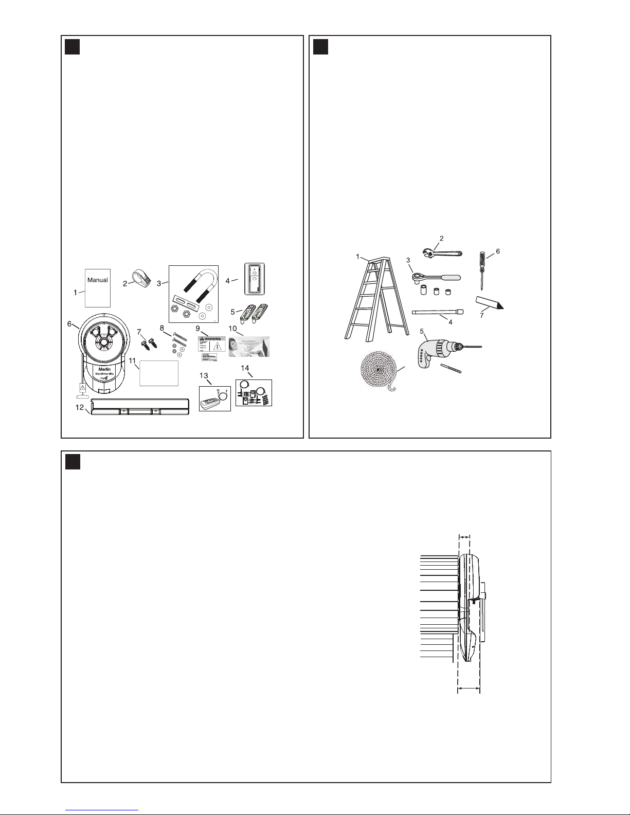
1. Instruction manual (this document)
2. Stop collar
3. Clamp bracket, plates, washers (2) and nuts (2)
4. E138M wireless wall button (1)
5. E960M Premium+ transmitter (2)
6. Opener
7. Self tapping screws (2)
8. Weight bar screws (2), washers (2) and nuts (2)
9. Warning label and risk of entrapment label
10. Warranty registration card
11. Quick start guide
12. Weight bar
13. MyQ Gateway (includes power pack)
14. Safety Beams (includes 15 cable tie mounts)
CARTON INVENTORY
1
Quick Start Guide
13 mm, 10mm, 8 mm
5.5 mm
Marker Pen
8
TOOLS REQUIRED
2
1. Ladder
2. Adjustable wrench for U-bolts already installed
on the door
3. 8 mm socket, 10 mm socket and 13 mm extended
socket and socket wrench
4. 300 mm socket extension (for minimum side-room
installations)
5. Drill and 5.5 mm drill bit
6. Philips-head screwdriver
7. Marker pen
8. Door stand or similar device to safely support door
(not shown)
DOOR REQUIREMENTS
3
Ensure that there is at least 45 mm from the edge of the curtain to the edge of the bracket. If the roller door
drum wheel is on the edge of the curtain or is a smaller diameter, additional clearance may be required.
Assemble the opener to the door axle and the exisitng door bracket using the U clamp assembly provided.
Tighten to 25-28 Nm. Full installation procedure is in section 13.
95 mm
Minimum distance from
edge of curtain to edge of
door bracket 45 mm
The SilentDrive Elite MyQ (MR865MYQ) is suitable for
spring balanced Residential Rolling garage doors with:
• Maximum door height of 4.5 m
• Maximum curtain area of 18 m
2
• Maximum door mass of 120 kg
*The Protector System
TM
must be installed for all myQ
installations and all other installations where the force at
the edge of the closing door exceeds 400 N (40 kgf).
Door axle diameter must not exceed 35 mm.
2
Page 4
3
DN
UP
P
S
6
6
1
2
3
7
A
B
C
B
D
2
3 4
5
8
1
DN
UP
1
2
3
P
S
1
A
B
C
B
D
8
2
3 4
5
6
6
7
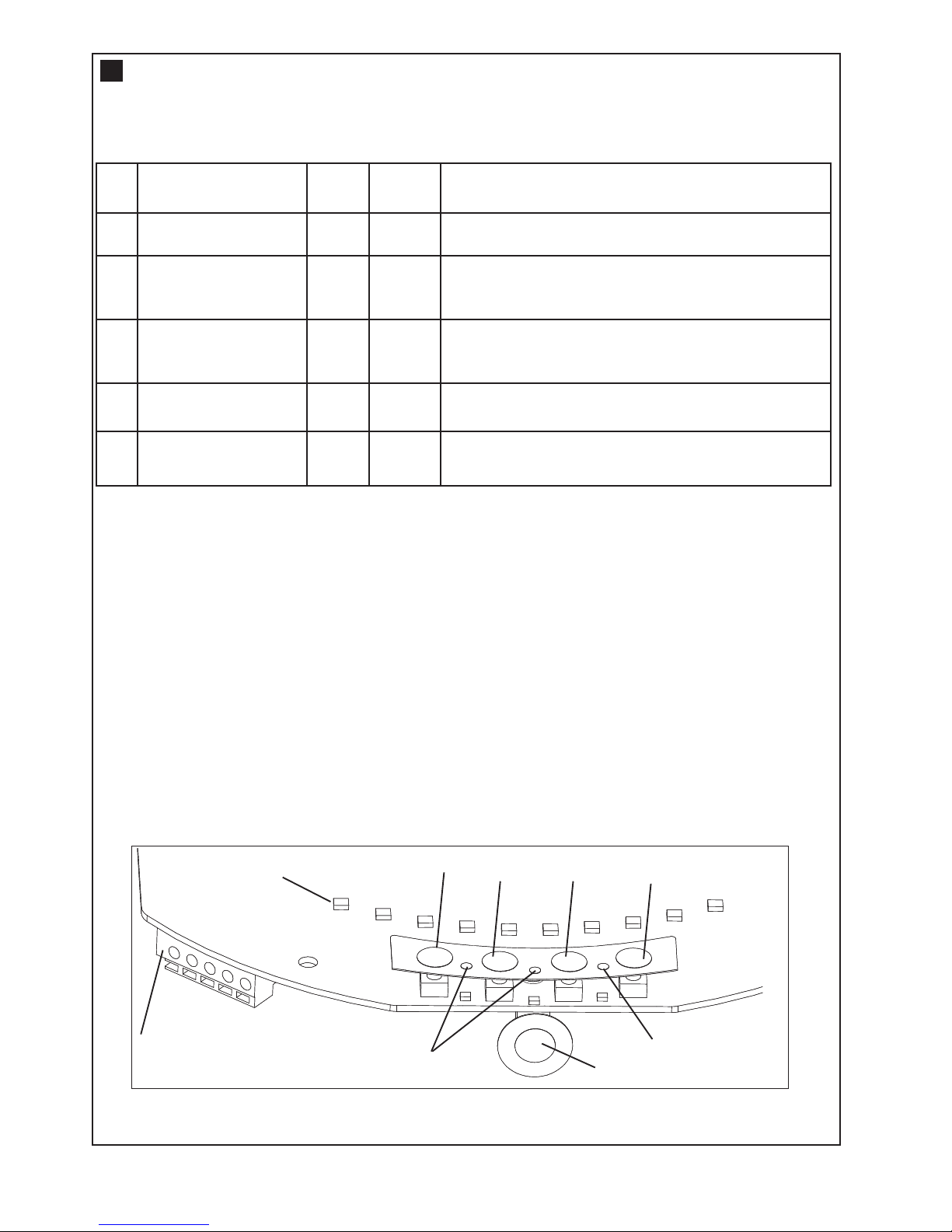
1. Terminal Block: used for external accessories (see chart below).
NOTE: The terminal block is behind a plastic cover in the back housing. Use a small screwdriver to lever
open the plastic cover if access to the terminal block is required. All wires should be secured appropriately.
2. DN Button: used to drive the door DOWN
3. UP Button: used to drive the door UP
4. P Button: used to “PROGRAM” the DOOR LIMITS (see section 14)
5. S Button: used to “SAVE” & “DELETE” the “REMOTE CONTROLS” and the “MYQ Internet Activation”.
6. LEDs: 1. Program DOWN, and Diagnostic code indicator Number 1
2. Program UP indicator
3. Diagnostic code indicator Number 2
7. Control Button: used to activate the door when remote controls are not available. Open - Stop - Close.
8. Courtesy Light: turns on during operation and automatically turns off after a period of 3 minutes
Ref Function
Colour
Polarity Comment
A
Push button
Red
+ve
Dry contact input for push button wired wall
controls
B
Common
White
-ve
Common terminal for push button, The Protector
System
TM
& accessory power
B Common White -ve Common terminal for push button, The Protector
SystemTM& accessory power
C The Protector System
TM
Grey
+ve
Merlin IR Beam Input (pulsing
type only) - see section 18
D
Accessory Power
Green
+ve
24v dc 50 mA accessory output available for a
universal receiver (output not active in Standby Mode)
CONTROL PANEL
4
Page 5
4
TESTING THE DOOR
5
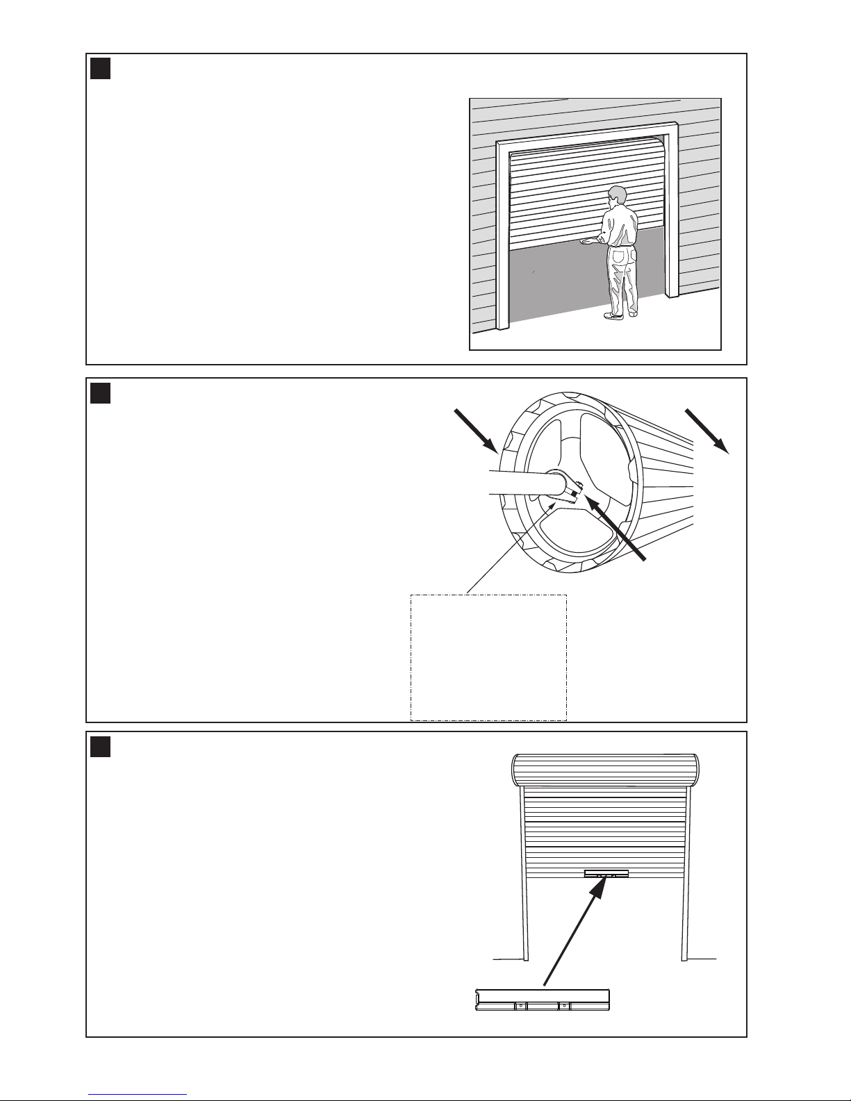
Complete the following test to ensure your door is well
balanced, and not sticking or binding:
• Disable all locks and remove any ropes connected to the
garage door.
• Lift the door to about halfway and then release it. The
door should remain spring balanced.
• Raise and lower the door to determine if there are any
sticking or binding points (20 kgf is the absolute maximum
allowable to raise or lower the door in any position).
If your door does not hold in place or the door binds or
sticks, call a qualified door technician before installing the
opener.
INSTALLING THE STOP COLLAR
6
If the door has a lifting handle, remove the handle, nuts &
bolts. Place the weight bar over the handle holes, insert the
extended bolts through the weight bar & fasten the handle
back in place.
• Place the weight bar in the centre of the door as shown.
If the door curtain does not have a handle you will need to
follow these instructions:
• Use a marker pen to mark the two hole positions.
• Drill two 5.5 mm holes through the two marked
positions, then place the weight bar on the inside of the
door.
• Use the bolts, washers and nuts (provided) to
fasten the weight bar in place.
INSTALLING THE WEIGHT BAR
7
Non opener side Opener side
Boss
SAFETY CHECK!
Is the stop collar installed?
YES: proceed to the next
step
NO: install the stop collar
before proceeding
• The stop collar is required to be installed on the
opposite side of the door to where the opener is to be
installed.
• Ensure the U-Bolt holding the door shaft to the door
bracket is tightly secure.
(NOTE: This U-Bolt must not be removed or loosened)
• Remove the bolt assembly from the plastic stop
collar. Open the collar as wide as possible and push
it onto the door shaft.
• Fit the stop collar hard against the boss of the
door drum. Reinstall the bolt assembly onto the
stop collar and tighten.
Page 6
5
PINNING THE DOOR
Free curtain
Ballooning
Add fasteners here
Door closed
Door can be
lifted
Door secure
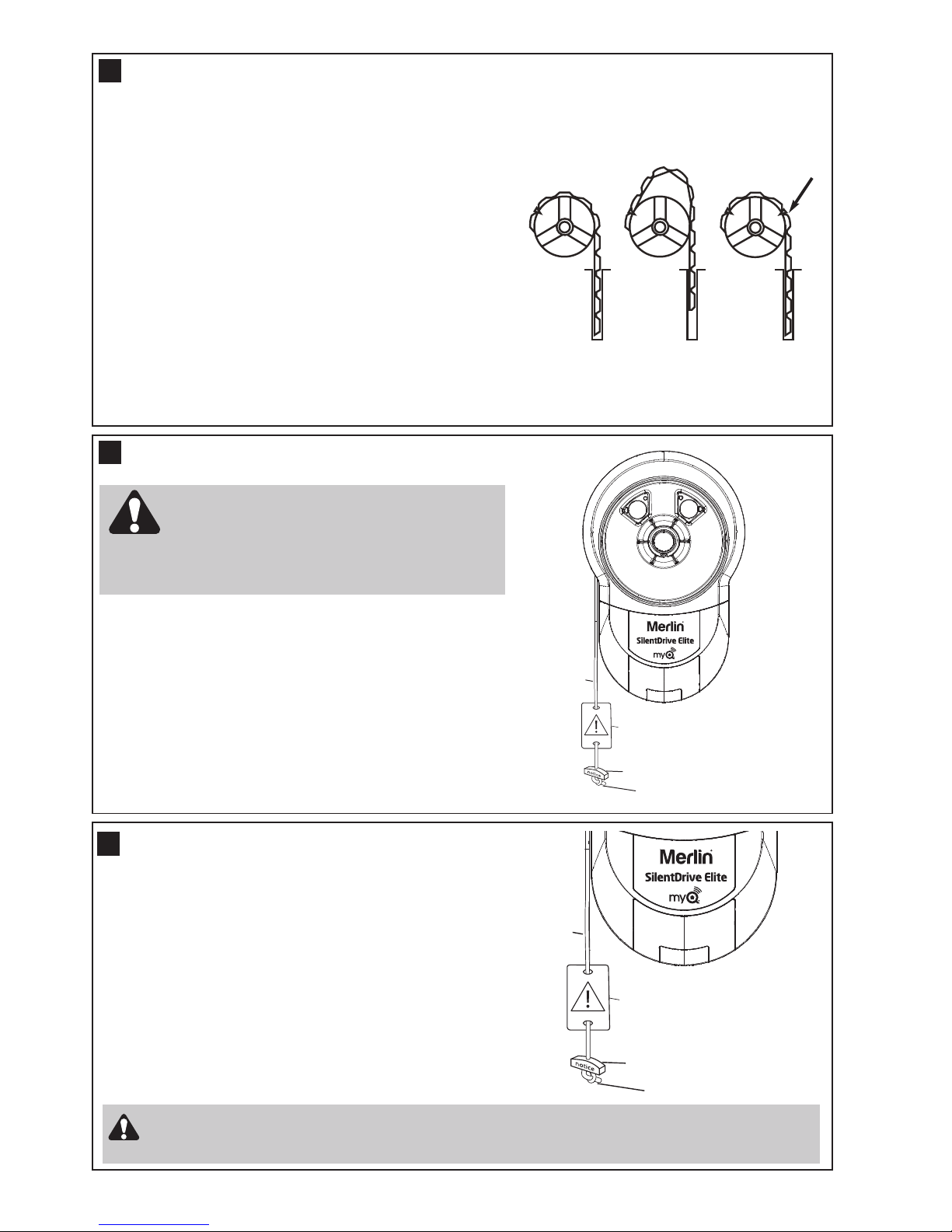
8
Note: A ballooning door may delay the safety reversal
response and can compromise garage door security.
• To remedy any ballooning, insert the supplied self tapping
metal screws into where the curtain leaves the roll. Secure
these through the curtain into the drum wheel at each end
of the roll.
• After determining the correct fastener location as shown, lift
the door approximately half a turn from the closed position
to allow access for securing the screws.
Rope
Manual release
warning label
Release handle
Overhand knot
THE RELEASE HANDLE & CORD
9
Rope
Manual release
warning label
Release handle
Overhand knot
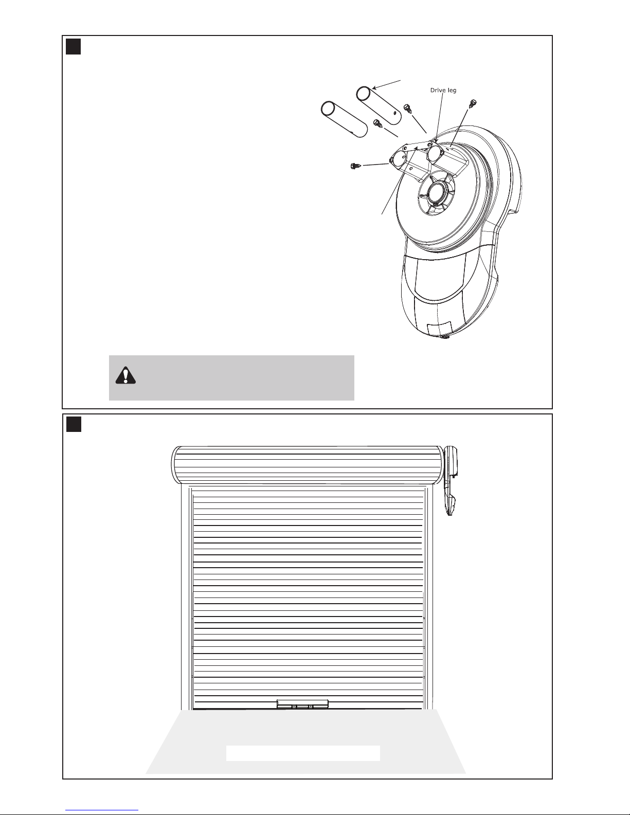
To disengage the opener
Pull the release cord down firmly,
(the opener will make a clicking noise).
To re-engage the opener
Pull the release cord down firmly,
(the opener will make a clicking noise).
Disable all locks and remove any ropes connected to the garage door.
Take care when operating the manual release as an open door may fall rapidly due to weak or
broken springs, or being out of balance.
OPERATING THE MANUAL RELEASE
10
The manual release mechanism enables the door to be
manually operated during power outages or in an emergency.
The RED Manual Release cord is preassembled to the
opener. When the opener is installed the handle should be no
higher then 1.8 metres from the floor. The cord may need to
be extended for high door installation.
Do not disengage the opener to manual operation
with children, persons or other objects including
motor vehicles within the doorway. The door is
under significant tension and if the door has developed a fault
or incorrect tension, it may be unsafe and may fall rapidly.
Page 7
6
LEFT / RIGHT HAND INSTALLATION
12
LEFT
(handing must
be changed
during limit
setting - refer to
section 14)
RIGHT
(factory
default
setting)
Inside garage looking out
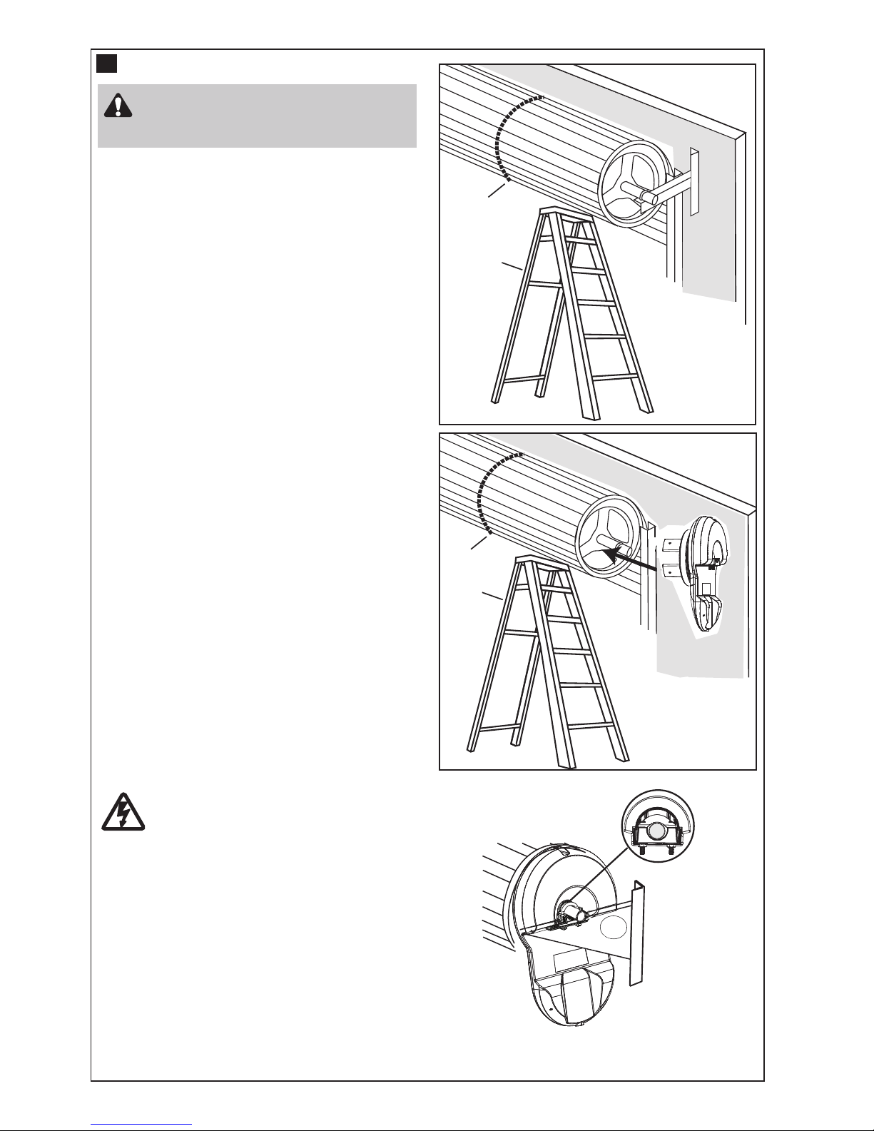
Extension pole
Reinforcing Brace
Optional accessory not provided
• Insert the extension poles into the drive legs.
• Align the holes on the extension poles with the holes
on the drive legs
• Using the screws provided, secure the extension poles
• Align the holes of the reinforcing brace with the two
holes on the end of the drive legs as shown and fix in
place using the screws provided. Please note that the
reinforcing brace MUST be applied.
ATTACHING EXTENSION POLES (IF REQUIRED)
11
Reinforcing brace must be used. Use
extension pole kit part number 002A1828
Page 8
7
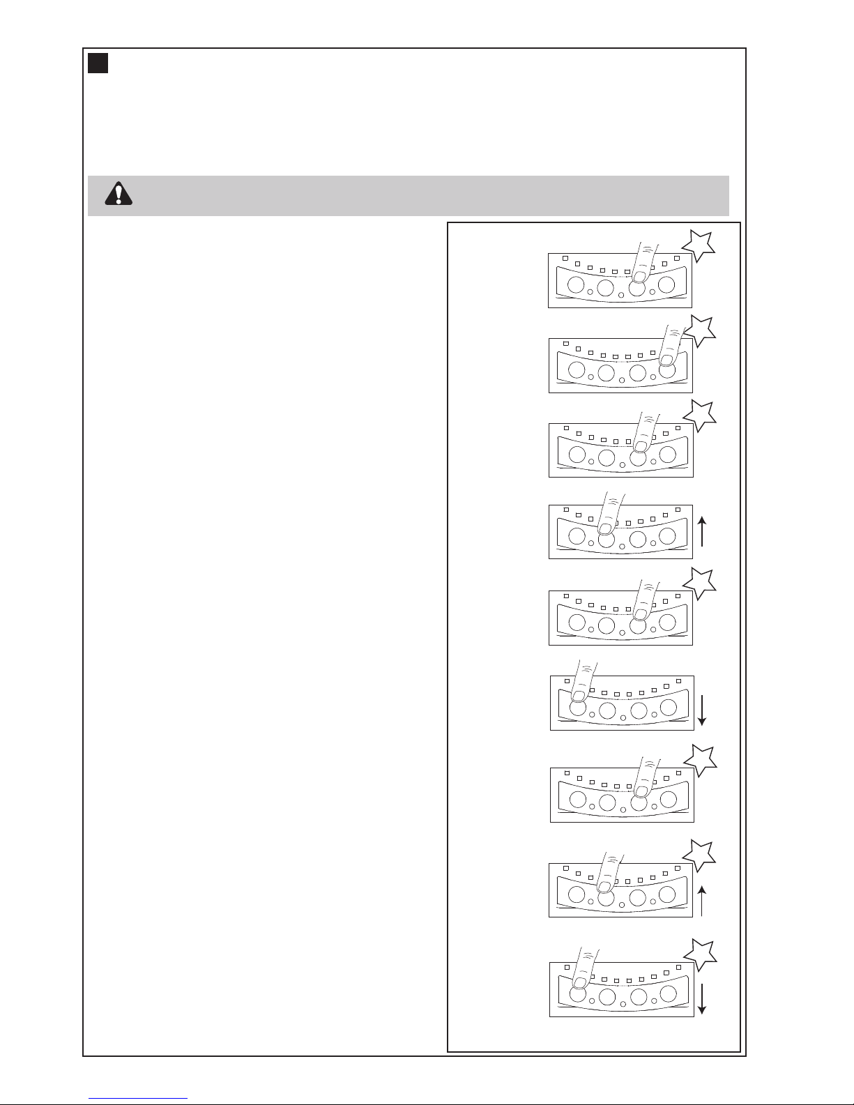
INSTALLATION PROCEDURE
NOTE: The opener can be installed on either side
of the door. The following instructions are for
RIGHT HAND INSTALLATIONS (as illustrated i.e.
inside the garage looking out). For left hand
installations, reverse the instruction terminology
(eg LEFT for RIGHT etc).
Preparation:
• Place the opener in manual release mode (refer to
section 9)
• Completely open the roller door. For safety,tie a rope
around the door
• Ensure the door axle U-BOLT and door mounting
bracket on the left hand side (non opener side) are
securely fastened
• Support the door with a door stand, ladder or similar
device to safely support the door
• Mark the position of the door shaft on the right hand
door bracket (for reassembly purposes)
• While the door is supported, remove the right hand
axle U-Bolt and door mounting bracket from the wall
Install the opener:
• Slide the opener over the door axle and engage the
drive legs into the door drum wheel, either side of a
spoke
• Refit the door mounting bracket to the wall
• Clamp the opener on the door axle and door bracket
in the marked position using the clamp assembly
supplied (tighten to 25 – 28 Nm)
• Remove all ropes and the support stand
• Check the operation of the door in manual mode by
raising and lowering by hand. It should operate
smoothly without sticking or binding. The disengage
handle should already be attached less than 1.8m
above the floor
Connect the power:
• Position the power cable away from the door curtain
and any moving parts
• Plug the opener into a nearby power point and turn
ON
• The opener light will turn ON and remain ON for 3
minutes
Rope
Ladder
Rope
Ladder
Tighten to
25-28 Nm
13
Do not allow people to walk under or
around the door during the installation
process as serious injury can occur.
Page 9
8
SETTING THE LIMITS FOR RIGHT OR LEFT HAND OPERATION AND FORCE
Travel limits set how far your door goes up and down. Your opener must also be configured for right or left hand
installation. If not the door will rotate in the reverse direction.
Program Buttons: The Control Panel diagram in section 4 identifies the Control Buttons and LED layout
Audible Beep: An audible “BEEP” also occurs with each button press. This feature can be turned OFF
Courtesy light: During the programming sequence, the courtesy light will flash at half strength
NOTE: The SilentDrive Elite MyQ (MR865MYQ) opener is factory configured for right hand installation.
14
132A2940
1. Program
Start
2. Left/Right
Setting
3. Accept
Setting
4. Set UP
Limit
5. Accept UP
Limit
6. Set DOWN
Limit
7. Accept
DOWN
Limit
8. Learn UP
Force
9. Learn
DOWN
Force
Flash x 2
BEEP
DOWN
DOWN
UP
UP
DNDN
UPUP PP
SS
11
22
33
Flash x 2
BEEP
DNDN
UPUP PP
SS
11
22
33
DNDN
UPUP PP
SS
11
22
33
DNDN
UPUP PP
SS
11
22
33
Flash x 2
BEEP
DNDN
UPUP PP
SS
11
22
33
Flash x 2
BEEP
DNDN
UPUP PP
SS
11
22
33
Full light
BEEP
DNDN
UPUP PP
SS
11
22
33
Flash x 2
BEEP
DNDN
UPUP PP
SS
11
22
33
Flash x 2
BEEP
DNDN
UPUP PP
SS
11
22
33
The opener will operate during this procedure. Make sure the door is clear of obstruction.
Ensure your hands are away from any moving parts before activating the door.
Setting the Right or Left Hand Operation:
Refer to the diagrams on the right for guidance.
Ensure the door is positioned halfway and the opener is
engaged (out of manual mode).
Turn the opener Power ON, the courtesy light will turn ON.
1. Press the “P” button for 5 seconds until LED 3 will flash,
as well as LED 2 or LED 1 will flash. For Right Hand
setting LED 2 will flash, and for Left Hand setting LED 1
will flash.
2. To change to the opposite setting, simply press the “S”
button, and the opposite LED will flash.
3. When the correct hand setting is selected, Press and
Release the “P” program button to accept this
setting. (continue)
Setting the Door Limits:
4. Press and hold the “UP” button until the door
reaches the desired OPEN position (You can toggle
between the “UP” and “DN” buttons to move the door to
the correct position. Make sure there is enough room
for your vehicle to pass under)
5. Press and release the “P” program button to
accept this setting.
6. Press and hold the “DN” button until the door
reaches the desired CLOSED position (You can
toggle between the UP and DN buttons to move the
door to the correct position.)
7. Press and release the “P” program button to
accept this setting. (LED 2 should flash to indicate
you are now in Force Learn mode) (continue)
Setting the Force Automatically:
8. Press and release the “UP” button. The door will travel to
the OPEN position with LED 2 flashing.
9. Press and release the “DN” button. The door will travel to
the CLOSED position with LED 1 flashing. When fully
closed, LED 1 will stop flashing and the courtesy light will
change to full power.
(This process is now complete)
Setting the Force manually: (Only perform if Limits are
already set)
• Start with the door fully CLOSED.
• Press the “S” button twice to enter into force learn mode.
The Courtesy light will go to half strength, and Led 2 will
flash quickly.
• Press and release the “UP” button. The door will travel to
the OPEN position, then LED 1 will flash quickly.
• Press and release the “DN” button. The door will travel to
the CLOSED position, then LED 1 will stop and the
courtesy light will change to full power.
This process is now complete.
Page 10

9
Handle should be
less than 1.8 m
<1.8 m
Once you have completed your installation and
successfully carried out the safety reverse system
test (outlined above), install the warning labels
provided with your opener as shown.
The risk of entrapment label must be installed
adjacent to the release handle at a height of less than
1.8 m from the floor.
The WARNING label must be installed in a prominent
place near any fixed control.
Any fixed wall control or wireless door control must be
mounted at a height of no less than 1.5 m out of the
reach of children.
Read the safety instructions (page 1) for further
details concerning safety.
FIXING WARNING LABELS
Operate the door in the down direction. The door must
reverse upon contact with the obstacle. If the door
stops on the obstacle, remove obstacle and repeat
limit and force setting (refer to section 14).
Repeat the safety reverse system test.
15
40 mm Test obstacle
40 mm
16
TESTING THE SAFETY REVERSE SYSTEM
The safety reverse system test is important.
The garage door must reverse on contact
with a 40 mm obstacle laid flat on the floor.
Failure to properly adjust the opener may result in
serious personal injury from a closing garage
door.
STANDARD INSTALLATION COMPLETE
INSTALLING YOUR E138M WIRELESS WALL BUTTON
To install:
• Carefully pry open the E138M and locate the two screws for
mounting.
• Attach to the wall using the two screws and wall anchors
provided if mounting to a plaster wall. If using a recessed wall
box do not use anchors.
NOTE: Do not overtighten screws.
+
17
Disconnect power to the opener whilst installing
this accessory to prevent accidental activation.
Locate minimum 1.5 m above the floor
NOTE: The wall control supplied with your opener should be pre-programmed by the factory.
If adding a new wall control, program into the opener before mounting the unit as detailed in
the “Wireless Programming” section.
Page 11

10
INSTALL THE PROTECTOR SYSTEMTM(compulsory for MyQ to operate)
To prevent entrapment, install
Safety Beams no higher than 100
mm above the floor.
Disconnect power to the garage
door opener before installing
Safety Beams.
18
NOTE: This accessory must be used for all MyQ
installations and all other installations where the closing
force as measured on the bottom of the door is over 400 N
(40 kgf).
SPECIAL NOTE: Merlin strongly recommends that The
Protector System
TM
be installed on all garage door
openers.
SAFETY BEAMS: By installing Safety Beams, an open door is
prevented from closing if a person or object is located in the
beam area. If the door is already closing, it will return to the
open position. A closed door is not prevented from opening.
If the Protector System
TM
is installed and needs to be removed,
the opener will need to be reprogrammed (refer to paragraph 9
of the troubleshooting section on page 23).
Assembly Process:
The Safety Beams are supplied preassembled, complete with
two sensors, wiring and wall brackets.
Install the mounting brackets and sensors to either side of the
inside of the garage door, and at a height of no greater than
100 mm off the garage floor.
The brackets are designed to be used for Wall or Floor fixing,
with a variety of hole combinations to achieve the desired
results (fig 1).
Drill the required holes and install the brackets with wall plugs
and screws provided. Ensure they do not obstruct the door
movement.
Align the Safety Beams to face each other and tighten if
necessary. The wiring should exit from the bottom of the
housing to maintain the correct IP rating and continued
operation.
One sensor is a Sending Eye , the other is a Receiving Eye. Try
to avoid positioning these in direct sunlight as this may interfere
with the operation of the beams.
Install Cabling:
Run both sets of Safety Beam cables up the door tracks, across
the door header and back to the Power Head (see fig 2 & 4).
Clean the contact area with alcohol wipes (provided) and
secure the self-adhesive Cable Mounts to the rails. Attach the
cable with cable ties.
Ensure the cable is well supported and does not interfere or get
damaged by movement of the door panels or spring hardware.
fig. 1
view 1
view 2
Cable Tie Mount
at the top
Cable Tie Mount
at the middle
Cable Tie Mount
close to the Beam
100 mm Cardboard
template
Beam and Bracket
assembly
fig. 2
Page 12

11
Connect cable to the Opener:
Disconnect the mains Power from the Opener.
At the Powerhead Control Panel remove the plastic break
out (see fig 3) to expose the “External Accessory Terminal
Block”.
Twist both WHITE wires together and both GREY wires
together.
Connect the WHITES to the white mark screw terminal of
the 2-way connector, and the GREYS to the grey mark
screw terminal (see fig 4).
Push the 2-way connector into the control panel quick
release terminals B & C (see fig 5).
Ensure the white wires go to B and the grey wires go to
C.
Loop and secure the excess cabling above the opener
assembly.
Test the Safety Beam operation:
Remove all obstacles from the path of the door. Connect
the mains Power to the opener.
1. Using a remote control, check the Opener operates in
both directions.
2. Obstruct the beams with the door fully OPEN, the door
should not move and the Courtesy light will Flash 10
times.
3. Obstruct the beams with the door travelling DOWN, the
door should STOP and return to the UP position. The
Courtesy light will Flash 10 times.
4. Obstruct the beams with the door travelling UP, the
door should continue to the OPEN position.
Status indicators on the Safety Beams:
Normal Operation -- Red LEDs “ON” constantly.
Low standby Mode -- Red LEDs “OFF”. (Leds
activate when door moves.)
Safety Beams misaligned- Red LEDs “FLASH”.
Safety Beams obstructed-- Red lLEDs “FLASH”.
For further diagnostics, refer to the TROUBLESHOOTING section at the rear of the Opener Handbook (on page
23).
Emergency Overide:
NOTE: The door canʼt be closed using the MyQ app if an obstruction of Safety Beam failure has occurred.
However, if needed, the door can be closed by using the programmed button of a Wireless Wall Control (E138M),
Keyless Entry Keypad (E840M) or the Control button located on the bottom of the opener.
Follow the process below:
With the door open Press the programmed button once and release.
Press and “HOLD” the button again, and continue to HOLD untl the door has completely closed.
NOTE: If the button is released at any point during the downward movement, the door will stop and return
to the OPEN position. In this case repeat the previous process again. The “DOOR CLOSE” process will
need to be performed each time the door needs to be CLOSED, until the obstruction is removed or repairs
are made to the Safety Beam System.
DN
UP
P
S
1
2
3
A
B
C
B
D
Grey x 2 White x 2
CABLE END
3 X CABLE TIE MO UNT
WITH CABLE TIE
OPENER
BEAM 1
BEAM 2
1 X 2-WAY CONNECTOR
WITH LEADS AND CABLE
COLOUR MARK
3 X CABLE TIE MO UNT
WITH CABLE TIE
White x2
Grey x2
Plastic Breakout
fig. 4
fig. 5
INSTALL THE PROTECTOR SYSTEMTM(CONTINUED)
fig. 3
Page 13

12
Featuring MyQ®Technology.
This Users Guide will help get the most from your Merlin MyQ
®
enabled Opener when using
a smartphone, tablet or computer to monitor and control your garage door opener away from
home.
The MyQ
®
Gateway System will operate with MERLIN products identified as MyQ®ENABLED.
MyQ®Gateway is an accessory feature and openers will operate as normal with remote controls, whether the MyQ
®
Gateway is connected or not.
• The Internet Gateway System: is designed to operate with Merlin Sectional and Rolling Garage Door
openers, and all the SAFETY INSTRUCTIONS detailed in the OPENER HANDBOOK need to be observed.
• Unattended Operation: The Gateway System allows operating the door via an internet enabled product, without
visual monitoring. Never allow anyone to pass through, or leave obstacles in the area of a moving garage door.
Persons, pets and vehicles should remain clear until the door has completely stopped.
• Automatic door: The door may operate unexpectedly, therefore do not allow anything to stay in the path of the
door.
• The Protector System
TM
: For SAFE operation of the door, The Protector SystemTMMUST BE INSTALLED (refer
section 18) and be fully functional. The door will not operate with MyQ technology if the The Protector System
TM
is
not functional.
• Do not allow children to play near the door, or with any door controls, including remotes, Smartphones, Tablets or
any internet device that has a Merlin MyQ
®
app installed.
• Power Pack: It is important to use the AC/DC PowerPack supplied with the product. If the power pack is damaged
or becomes unserviceable, it must be replaced with an ANZ Compliant product, of the same electrical performance.
INSTALLATION INSTRUCTIONS
A . BEFORE YOU BEGIN: you must have -
• A Merlin Enabled garage door opener. (MyQ
®
enabled)
• A home Router, with an active Broadband internet connection.
• Internet Gateway Kit (contents are listed below)
• MyQ®Internet Gateway Module 828 AU
• 5 VDC Power Pack
• Ethernet cable
• Safety Beams 774ANZ
• MyQ
®
Quick Start Guide
• Merlin Internet Gateway Installer/Users Guide
B. INSTALLATION PROCESS:
• Garage Door opener:
Install the Merlin Garage Door Opener to a fully functional door using the Installation Instructions supplied
with the product.
• Protector Safety System:
Install the Merlin Protector System supplied with the MyQ
®
Gateway kit, using the Installation Instructions
supplied with the product.
Note: The Safety Beams must be installed and operational for MyQ
®
to function.
• MyQ®Gateway:
Connect & Create the MyQ
®
Gateway using the following process.
MERLIN MYQ GATEWAY INSTALLION & USER GUIDE
19
MYQGATEWAY INSTALLATION
WARNING: Important Safety Instructions:
To prevent possible serious injury/death, or property damage read and follow all instructions carefully.
Page 14

13
MERLIN INTERNET MyQ®GATEWAY USERʼS GUIDE
Step 1 - Connect & Create
• See the “Merlin MyQ®Quick Start Guide” for instructions for the connection of
your Merlin Internet Gateway to the Internet. Go to mymerlin.com.au or
mymerlin.co.nz or download the Merlin MyQ App to create an account and connect the Internet Gateway.
• You must have a valid email address to create a Merlin MyQ
®
account. Enter your information and click
submit, an email will be sent to you to confirm your valid email address. If you do not get a confirming email,
check your spam email folder or try creating the account again, being careful to spell the email address
correctly.
• When the Merlin Internet Gateway powers up, the GREEN LED and BLUE LED will blink 3 times to
indicate a correct power connection and reset of the Internet Gateway. After power up, the LEDs will indicate
the status of the Merlin Internet Gateway. Refer to the “Gateway Diagnostics/Status LEDs” step for details
regarding the LED indicators.
• If the GREEN LED is off after connecting the Merlin Internet Gateway to your router, check the Ethernet
cable connection to your router. It must be in the LAN port, (normally numbered 1 – 4). If the GREEN LED is
still off, try another port on your router. If you still cannot get a solid GREEN LED check your internet is ON,
refer to gomerlin.com.au or gomerlin.co.nz. For further support contact Merlin Technical
Support at customerservice@chamberlainanz.com.
Step 2 - Register Merlin Internet Gateway & Add Devices
Once you have successfully created your Merlin MyQ®account, you must add the Merlin Internet Gateway to
the account. It is easy to do from a computer or your internet enabled smartphone or tablet. See step 3 for
downloading the Merlin MyQ
®
app and steps 5 and 6 for using the app.
• To add the Merlin Internet Gateway to your account, the GREEN LED on the Internet Gateway must be
on continuously. If the GREEN LED is not continuosly on, see Step 1, Connect & Create. The Merlin
Internet Gateway must have an internet connection for the website or phone to find it.
• In the mymerlin.com.au or mymerlin.co.nz websites, add the Merlin Internet Gateway. Click
on “Manage Places” to add the Internet Gateway. If this is the first Merlin Internet Gateway connected to
the account, the screen will already be at the step of “Register Gateway”. You will need the SERIAL NUMBER
from the bottom label of the Internet Gateway. The serial number is a series of ten characters, 0 – 9 or a – f.
Be sure to use the correct characters (e.g., a zero “0” instead of an “O”) and keep the character spacing
correct (XXXX-XXX-XXX). If this is the second Merlin Internet Gateway to be added, just click on
“Manage Places > Add New Place”. For instructions on how to complete this step with the Merlin MyQ
®
app, see steps 5 and 6.
• Name the Merlin Internet Gateway (e.g., “123 Main Street” or “Home Sweet Home”). Click “Save and
Close” to complete this step.
• You can add MyQ
®
devices like the garage door opener from the “Manage Places” page, or you can
download the Merlin MyQ
®
app and add any MyQ®device from a smartphone or tablet. To add the garage
door opener, click on “Manage Places>Add New Device” and follow the steps. Once you click ADD you have
3 minutes to go to the garage door opener or device and press itʼs learn button. The Merlin Internet
Gateway will pair to the opener. Once a device is programmed, it will appear on the screen. You can then
name the device (e.g., left garage door, etc.).
Page 15

14
Step 3 - Getting A Smartphone App
If you have an older OS, the phone or tablet will not be able to locate the Merlin
MyQ®app. You may need to upgrade the phoneʼs OS to be able to find,
download, and use the Merlin MyQ®app. Smartphone apps are available for
Apple
®
and Android™ devices:
• Apple®iPhone®, iPad®, and iPod Touch
®
- Visit the Apple App StoreSMfrom your Apple device to download the
Merlin MyQ®app (search for "MyQ" by The Merlin Group,
Inc.For iPad, change settings to include iPhone Apps).
• Android™ smartphones and tablets
- Visit Google Play from your smartphone to download the Merlin
MyQ
®
app (search for "MyQ" by The Merlin Group, Inc.).
• BlackBerry
®
, Windows, and other smartphones
- You can access your MyQ®account to monitor and control your garage
door opener on other smartphones by pointing your phone's browser to
mymerlin.com.au or mymerlin.co.nz
- Bookmark this page for later use.
- The mobile website has the same functionality as the smartphone apps.
After the app is installed on your smartphone, you can add a new
device to your account by following the instructions for your smartphone in Steps 5 – 6.
Step 4 - Changing Merlin MyQ®App Security Settings
You can change the SECURITY SETTINGS (see steps 5 & 6) of the Merlin MyQ®app to allow quicker access
to your devices and account. The default security setting for the app is at the highest level. You must enter your
email and password credentials every time to launch the app or to access and change your account settings.
The security settings apply to each individual phone, so each phone tied to the same account must be
configured separately. These settings do not affect the web page login. A four-Digit PASSCODE can be created
in place of your email and password credentials. See “Creating a Passcode” below.
Default Merlin MyQ®App Security Settings
• Launching App – high security is initially set to ON. You must enter your email and password credentials
every time the app is launched. Setting this to OFF allows the app to launch without requiring your credentials
or a 4-digit passcode.
• Accessing Account – high security is initially set to OFF. This lets you access your account settings without
requiring your credentials or a 4-digit passcode. Setting this to ON will require you to enter the email &
password credentials every time you want to access your account settings.
• Touch ID –Touch ID is a fingerprint security login, that is available for Apple users with the fingerprint feature
incorporated. When Touch ID is set for login, the user will see a fingerprint on the login screen.
Note: Touch ID is available on iPhone 5S or later and iPad Pro, iPad Air 2, or iPad mini 3 or later.
• Opening Door – high security initially set to OFF. If you turn it ON, you must enter your email and password
credentials or a 4-digit passcode every time you want to use the app to open your door. Setting this to OFF
lets you open your door without requiring your credentials or a 4-digit passcode. It is strongly recommended
that if you turn OFF the security settings for launching the app, you set this function to ON and create a 4-digit
passcode for opening the door. This prevents anyone from using your phone to get into your garage.
Creating a Passcode
• The passcode is four characters (numbers or letters, depending on your smartphone).
• When you create your 4-digit passcode, the app will ask for the passcode twice.
• If you use the “Account > Logout” function on the smartphone, your passcode will be automatically deleted;
restarting the app will require the creation of a new passcode.
• See the section on your smartphone (Apple or Android) for specific instructions on how to create a 4-digit
passcode.
AccountEmail
Password
Rememberme
Login
®2013ChamberlainGroup, Inc.
Page 16

15
Step 5 - Apple App Controls
Controlling a device (a garage door opener)
Go to Places
- Swipe left or right to select a device
(to see more than one door).
- Tap the door image to open/close
door.
- If a device is greyed out, it is
currently unavailable.
Security settings (see step 4 for details)
Go to Accounts > My Account > Security
- Set security for launching app.
- Set security for accessing account.
- Set security for opening garage door.
If security is set to ON, you must enter email and password, or 4-digit passcode.
Setting a 4-digit passcode
Go to Accounts > My Account > Security > Passcode
- Enter a 4-digit passcode; you must enter this twice.
The 4-digit passcode now replaces email and password for security.
The 4-digit passcode is deleted if you logout; restarting the app will require the creation of a new passcode.
Add/delete/rename a device (a garage door opener)
Go to Places; tap the gear in the upper left corner of the screen.
To Add:
- Tap the Merlin Internet Gateway name
- Tap Add New Device
To Delete:
- Tap the Merlin Internet Gateway name
- Tap Edit
- Tap the “-“ (minus sign)
To Rename:
- Tap the Merlin Internet Gateway name
- Tap Edit
- Tap the deviceʼs name and enter a new name
Add/delete/rename a Merlin Internet Gateway
Go to Places; tap the gear in the upper left corner of the screen
To Add:
- Tap the “+” (plus)
To Delete:
- Tap the “-“ (minus)
To Rename:
- Tap the Merlin Internet Gateway name
- Tap Edit
- Tap the Internet Gateway name and enter a new name
Logging out
- A logout requires an email and password to restart the app.
- A logout will delete the passcode; restarting the app will
require the creation of a new passcode.
Apple
iPhone,
iPad,
or
iPod Touch
Page 17

16
Step 6 - Android App Controls
Controlling a device (a garage door opener)
Go to Places
- Swipe right or left to select a device
(to see more than one door).
- Tap the door image to open/close
door.
- If a device is greyed out, it is
currently unavailable.
Security settings (see step 4 for details)
Go to Account tab > Tap “My Account” > Tap Security
- Set security for launching app.
- Set security for accessing account.
- Set security for opening garage door.
Tap “Done” to save settings.
If security is set to ON, you must enter email and password, or 4-digit passcode. A logout will delete the
passcode; restarting the app will require the creation of a new passcode.
Setting a passcode
Go to Account tab > Tap “My Account” > Tap “Passcode”
- Enter a 4-digit passcode(PIN); you must enter this twice.
The 4-digit passcode now replaces email and password for security.
Add/delete/rename a device (a garage door opener)
Go to Places tab > Menu button > Manage Places
Select your place (Merlin Internet Gateway)
To Add:
- Menu button > Add New Device
- Then follow instructions
To Delete:
- Press and hold the device name
- Tap “Delete Device”
To Rename:
- Tap deviceʼs name
- Rename, then select “Save” to save changes
Add/delete/rename a Merlin Internet Gateway
Go to Places > Menu button > Manage Places
To Add:
- Menu button > Add New
- Then follow instructions
To Delete:
- Press and hold places name
- Tap “Delete Gateway”
To Rename:
- Press and hold places name
- Tap “Edit”
- Rename, then select “Save” to save changes
Logging out
Go to Account tab > Menu button > Log Out
- A logout requires an email and password to restart the app.
- A logout will delete the passcode; restarting the app will
require the creation of a new passcode.
Page 18

17
Step 7 - Alerts
The alert feature allows MyQ®users to receive an electronic notification (alert)
when a certain event occurs (e.g. the garage door opens or closes). An alert can
be enabled, edited, or disabled with any internet enabled computer or
smartphone. Multiple alerts can be enabled for any garage door opener. An alert
can be received on an internet enabled smartphone or computer from anywhere
in the world.
Event Options:
• Door opens/closes
• Door remains open for an extended period of time
Event Settings:
• All times and all days
• Specific days of the week (e.g. weekends only)
• Specific time (e.g. 8:00 am to 6:00 pm)
Schedules:
• With the schedules feature you can program the Opener to CLOSE at any time/day of the week. Set your
door on a nightly close schedule to ensure itʼs always closed before you go to bed.
Alerts can active with this feature. Note: Door Opening cannot be programmed.
Alert Options:
• Email – An alert will be sent to the MyQ®account email address
• Push Notification – An alert will be sent to each smartphone/tablet with the Merlin MyQ
®
app installed
that has logged into the MyQ®account at least once. NOTE: Push notifications can be enabled/disabled
through the smartphone or tablet settings.
• An email and push notification can be received simultaneously.
Event History
Whenever the designated event occurs the event history will display the event, including the time and day of
the occurrence. The event history can be deleted. An event history is recorded only in the fully OPEN and fully
CLOSED positions, and only when ALERTS are activated.
Gateway Diagnostics / Status LEDs
What do the LEDs on the Merlin Internet Gateway signify?
• The GREEN LED must be on continuously after power and network connections are completed (NOTE: The
LED may blink intermittently with data traffic).
• GREEN LED Off – The router is not providing an IP address to the Merlin Internet Gateway. Check your
router settings and internet connections.
• GREEN LED flashing steadily On & Off – The Merlin Internet Gateway has an IP address, but is not
accessing the Internet. Check your router settings and internet connections.
• GREEN LED On Solid – The Merlin Internet Gateway has an IP address and is connected to the
Internet.
• The BLUE LED indicates the Merlin Internet Gateway has programmed at least one device (a garage
door opener). The blue LED does not indicate if devices are connected; it only indicates that the Internet
Gateway has “programmed” one device to its memory.
• The YELLOW LED indicates the Merlin Internet Gateway is in the “Add New Device” or learn mode,
otherwise the LED will remain off.
Changing Merlin MyQ®App Security Settings
• You can change the SECURITY SETTINGS of the Merlin MyQ®app for quicker access to your devices
and your account. The default security setting for the app is high. If desired, you can lower the Security
Settings of the app. See Steps 5 & 6.
IMPORTANT NOTE: The Merlin MyQ
®
app is designed to work with Android™ smartphones and select
Android™ tablets. Full functionality of the Merlin MyQ
®
app on Android™ tablets may not be available.
iPhone®is a registered trademark of Apple Inc. Android™ is a registered trademark of Google Inc. BlackBerry®is a registered trademark
Research In Motion Limited
Page 19

18
The door may operate unexpectedly, therefore do not allow anything to obstruct the path of the
door.
TIMER TO CLOSE feature: (TTC) 10 to 180 seconds.
NOTE: The Protector SystemTMmust be installed before TTC will operate.
The Timer to Close feature allows the door to automatically close after a specified time period. During the
OPEN door waiting period, the courtesy light will flash continuoulsy.
If the door encounters an obstruction while closing, the opener will
return to the OPEN position and the waiting period will begin again.
To activate the Timer to Close:
• Start with obstruction detection beams installed and the door fully
CLOSED
• Press and Hold both “P” and “DN” buttons for 3 seconds. When the
Courtesy light flashes “TWICE”, release both buttons
• Press the “UP” for each 10 second interval required for
Timer to Close. A “BEEP” will register for each press. “DN” button
will reduce the count if needed.
• Press and release the “P” button to accept this setting
To deactivate the Timer to Close:
• Start with the door fully CLOSED
• Press and Hold both “P” and “DN” buttons for 3 seconds. When the
Courtesy light flashes “TWICE”, release both buttons.
• Press and release the “P” button to accept this setting
Auto close is NOT recommended for households with young children.
ACTIVATE
TIMER TO
CLOSE
SET
TIME
ACCEPT
SETTING
Flash x 2
BEEP
DNDN
UPUP PP
SS
11
22
33
BEEP
DNDN
UPUP PP
SS
11
22
33
Flash x 2
BEEP
DNDN
UPUP PP
SS
11
22
33
TIMER TO CLOSE FEATURE(TTC)
20
BEEP
AUDIBLE BEEP (OPTIONAL)
AUDIBLE
BEEP
Flash x 2
BEEP
DNDN
UPUP PP
SS
11
22
33
The SilentDrive Elite MyQ (MR865MYQ) has been
factory set for an audible “BEEP”.
The Audible beep can be turned OFF by using the
following method.
• Start with the door fully CLOSED.
• Press and Hold both “S” and “DN” buttons
for 3 seconds
• The Courtesy light will flash “TWICE”.
Release the buttons.
To turn the audible beep back ON, simply repeat the
above process.
21
Page 20

19
VENTILATION MODE - PARTIAL OPENING FEATURE
23
This is an adjustable, second stop position, that can be pre-set,
partially opened for ventilation, for pedestrian or pet access.
It is only operational with hand held remote controls, not Wireless Wall
Controls (E138M).
MyQ Activation: It is not a normal feature of the MyQ phone App,
however, from the pre-set position, an open door can be fully
“CLOSED”ʻ but a closed door cannot be “OPENED” to the pre-set
position.
To activate the ventilation mode:
1.Start with the door fully CLOSED (figure 1). Drive the opener UP
and stop at the position required for you wish to set the door at.
2.Enter ventilation activation mode by pressing the P and UP buttons
together for 3 seconds (figure 2). Release when the courtesy light
flashes once.
3.Press the remote control button that you have allocated for this
feature (figure 3). Do not use the button already allocated for normal
operation. The courtesy light will flash when the code is accepted.
The remote will now operate to and from the “programmed” and the
“fully closed position”. Outside this range the remote will operate as
normal.
To Deactivate the Partial Opening Feature:
1.Start with the door fully CLOSED.
2.Enter ventilation mode by pressing the P and UP buttons together for 3 seconds (figure 2). The courtesy
light will flash twice, indicating that deactivation has occurred.
fig.3
Flash
x 2
Door Fully Closed
fig.1
fig.2
BEEP
DNDN
UPUP PP
SS
11
22
33
Flash
x 1
BEEP
DNDN
UPUP PP
SS
11
22
33
STANDBY MODE (OPTIONAL)
22
The SilentDrive Elite MyQ MR865MYQ has been
factory set for Low Standby mode (sub 1 watt
usage).
This will deliver the lowest possible standby power. The
External Accessory Power is turned OFF in this mode,
so if this output is required, Normal Standby mode will
need to be activated (eg. for using an external receiver).
To Activate NORMAL STANDBY mode.
• Turn the mains power OFF.
• Press and Hold both “UP” and “DN” buttons.
• Turn ON mains power while both buttons are
still pressed.
• Courtesy light comes ON, and after 5
seconds another 10 flashes. Release both
buttons.
To Activate LOW STANDBY mode:
• Turn the mains power OFF.
• Press and Hold both “UP” and “DN” buttons.
• Turn ON mains power while both buttons are
still pressed.
• Courtesy light comes ON, and after 5
seconds another 1 flash. Release both
buttons.
Flash x 10
NORMAL
STANDBY
LOW
STANDBY
BEEP
DNDN
UPUP PP
SS
11
22
33
Flash x 1
BEEP
DNDN
UPUP PP
SS
11
22
33
Page 21

20
NOTE: The transmitters and wireless wall button supplied with
your opener are preprogrammed by the factory.
If you purchase additional transmitters, the garage door opener must
be programmed to accept the new remote code.
Program the receiver to match additional transmitter codes:
Using the “S” SAVE Button
1.Press and hold the button on the remote that you wish to use (1)
2.Press the “S” button on the opener for 1 second (2)
3.Release the remote button when the courtesy light flashes twice. It
has learnt the code. If you release the remote control push button
before the opener light flashes, the opener has not learnt the code.
Now the opener will operate when the remote control button is pressed.
To Erase all Remote Control Codes:
1.Press and hold the “S” button on the opener until the courtesy light flashes twice, and continue holding for
approximately 8 seconds, until the courtesy light flashes twice again.
2.Release the button, all remote codes are now erased.
To Erase all Remote Control and the MyQ activation code:
1.Press and hold the “S” button on the opener until the courtesy light flashes twice, and continue holding for
approximately 8 seconds, until the courtesy light flashes twice again.
2.Release the button and immediately Press and Hold the “S” button again to repeat step 1.
3. Release the button, all remote and MyQ codes are now erased.
Activate the opener only when door is in full view, free of obstruction and properly adjusted.
No one should enter or leave the garage while the door is in motion. Do not allow children to
operate push buttons or remotes. Do not allow children to play near the door.
1
2
Flash x 2
BEEP
DNDN
UPUP PP
SS
11
22
33
or
24
WIRELESS PROGRAMMING (REMOTE ACCESSORIES)
Page 22

21
OPERATION OF YOUR OPENER
Your opener can be activated by any of the following
devices:
• Opener Control Panel: UP & DOWN buttons, and
O.S.C. control button.
• Remote Control Transmitter: hold the button down
until the door starts to move.
• Wireless Entry Keypad: This is an optional accessory
that opens the door using a four digit keycode.
• MyQ Internet device: smartphone or tablet.
When the opener is activated by remote control:
• If open, the door will close. If closed, the door will open
• If closing, the door will stop
• If opening, the door will stop (allowing space for entry
and exit of pets and for ventilation)
• If the door has been stopped in a partially open or
closed position, it will reverse direction
Obstruction behaviour:
• If an obstruction is encountered while closing, the door
will reverse
• If an obstruction is encountered while opening, the door
will reverse and stop
• The Safety Beams use an invisible beam
which, when broken by an obstruction, causes a
closing door to open and prevents an open door from
closing. It is STRONGLY RECOMMENDED for
homeowners with young children or pets.
Opening the door manually:
The door can be opened manually by pulling the
release cord down firmly.
To re-engage the door, pull the release cord down
firmly.
The opener light will turn on for 3 minutes when the
opener is activated.
MAINTENANCE OF YOUR OPENER
Once a Month:
• Repeat the safety reverse test (see section 15).
Make any necessary adjustments.
• Manually operate the door. If it is unbalanced or
binding, call for professional garage door service.
• Check to be sure that the door opens and closes fully.
Set the limits and/or force if necessary.
SPECIAL NOTE: Merlin strongly recommends that The Protector SystemTMbe installed on all garage door openers.
CARE OF YOUR OPENER
When properly installed, your opener will operate with
minimal maintenance. The opener does not require
additional lubrication.
Limit and Force Settings: These settings must be
checked and properly set when the opener is installed.
Weather conditions may cause some minor changes in
the door operation, requiring some re-adjustments,
particularly during the first year of operation. Refer to
limit and force setting in, section 14.
Follow the instructions carefully and repeat the
safety reverse test after any adjustment.
Transmitter:Additional transmitters can be purchased
at any time. Refer to gomerlin.com.au or
gomerlin.co.nz for compatible transmitters. Any new
transmitters must be programmed into the opener.
Transmitterbattery: If the transmission range
decreases, replace the battery.
SPECIFICATIONS SILENTDRIVE ELITE MYQ
(MR865MYQ)
Input Voltage: 220-240 VAC, 50-60 Hz, 140 W
Rated Load: 35 Nm
Max.Pull Force: 550 N @ O300 mm
Max. door weight: 120 kg
Max lift under Spring Tension: 20 kg
Max. door area: 18 m
2
Standby Power: < 1 watt
Drive: DC gear motor permanent
lubrication
Max. Drum Rotations: 4
1/
2
Memory Registers: 64
Operating Frequency: 433.30/433.92/434.54 MHz
Operating Temperature: 55
0
C to -250C
When releasing the door, the door should
be fully closed if possible. Weak or broken
springs could allow an open door to fall
rapidly. Property damage or serious injury
could result.
Page 23

22
white
grey
24 vdc
com
External
Receiver
Wired Wall Button
com
n/o
4 3 2 2 1
Obstruction Detection Beams
green (4) grey (3) white (2) red (1)
TYPICAL WIRING DIAGRAM SILENTDRIVE ELITE MYQ (MR865MYQ)
Information for Service Personnel
25
Battery of the remote control:
The batteries in the remote have a long life.
If the transmission range decreases, the batteries should be replaced. Batteries are not covered by the warranty.
Replacing battery (CR2032
or equivalent):
To replace the battery, turn
the remote control around
and open the case with a
screwdriver. Lift the cover
and lift the control board.
Slide the battery to one side
and remove the old battery.
Be sure to observe the
polarity of the battery.
Assemble the transmitter again following the steps in reverse.
To prevent SERIOUS INJURY OR DEATH: observe the following instructions for the battery
- NEVER allow small children near batteries.
- If battery is swallowed, immediately notify a Doctor.
- Danger of explosion if battery is replaced improperly.
- Replacement only by identical or equivalent type.
- Dispose of old battery properly. Batteries should not be treated as household waste. All consumers
are required by law to dispose of batteries properly at the designated collection points.
- Never recharge batteries that are not meant to be recharged.
- Do not short-circuit batteries or take them apart.
- If necessary, clean contacts on batteries and contacts before loading.
- Never expose batteries to excessive heat such as sunshine, fire or the like!
or
Carefully
RemoveBattery
(CR2032x 1)
1
2VD
C
Pb Cd Hg
26
REPLACE BATTERIES IN REMOTES
Page 24

23
TROUBLESHOOTING
1. The opener will not operate from either the
UP/DOWN activation button or the transmitters :
• Does the opener have electric power? Plug a lamp into
the outlet. If it does not work, check the fuse box.
• Have you disabled all door locks? Review the
installation instruction warnings on page 1.
• Is there a build-up of ice or snow under the door? The
door may be frozen to the ground. Remove any
restriction.
• The garage door spring may be broken. Have it
replaced by contacting a garage door repairer.
2. The door operates from the UP/DOWN activation
buttons but not from the wireless wall control or
transmitter:
• Program the opener to match the transmitter code.
• Repeat with all transmitters.
• Check and replace the batteries if necessary
3. The transmitter has short range:
• Change the location of the transmitter.
• Check to be sure the antenna on the bottom of the
opener extends fully downward.
• Some installations may have shorter range due to a
metal door, foil backed insulation, or metal garage
siding.
• The batteries may be flat. Replace the batteries.
4. The door operates from the remote controls, but
not from the MYQ Internet device. (Iphone app etc):
• Check your internet service and router is active. (Are
other household devices operational?)
• Check the MyQ Gateway Device is On and Connected.
(refer to page 17 to confirm the Green and Blue led
status is correct)
• Confirm your Merlin MyQ APP is functioning, use the
website to confirm the system is operational.
• If the door will only OPEN, check the safety beams are
not obstructed.
• For other issues relating to MyQ activation, there are
FAQs available on the Merlin MyQ APP that may
assist.
5. The garage door opens and closes by itself:
• Be sure that no transmitter buttons are being pressed.
• Clear the memory and re-program all wireless wall
controls and transmitters.
6. The door reverses and stops before opening
completely:
• Is something obstructing the door? Is it out of balance,
or are the springs broken? Remove the obstruction or
repair the door.
7. The LED Indicators on the control panel are
flashing in sequence:
• Check the diagnostic code on page 25.
27
8. The door opens but will not close (or reverses
while closing):
• Is something obstructing the door? Pull the manual
release handle. Operate the door manually. If it is
unbalanced or binding, call a trained door systems
technician.
• Clear any ice or snow from the garage floor area where
the door closes.
• Repeat the limit and force setting. Repeat safety
reverse test after adjustments.
9. Door reverses for no apparent reason and
opener lights flash 10 times:
• Check the Protector SystemTM(if you have installed
this accessory). If the red light on the beam is
flashing, the alignment is incorrect.
• The red light on the beams may not be on if the
opener is in Standby mode. Activate the door to
temporarily exit standby mode and check lights are
on constantly. If the LEDs are flashing, realign the
beams.
If the Protector SystemTMis installed and needs to be
removed, the Opener will need to be programmed as
follows:
Note: MyQ Internet Activation will no longer
function.
• Remove the IR Beam wiring from the opener
• Turn the power OFF for 5 seconds
• Turn the power ON for 5 seconds
• Again turn the power OFF for 5 seconds
• Turn the power back on and test the opener for
normal operation.
10. The opener strains to operate the door:
• The door may be out of balance or the springs may
be broken. Close the door and use the manual
release to disconnect the door. Open and close the
door manually. A properly balanced door will stay in
any point of travel while being supported entirely by
its springs. If it does not, disconnect the opener and
call a trained door systems technician.
11. The opener motor hums briefly, then will not
work:
• Check that the door is not in manual release mode
(refer to section 6).
• The garage door springs may be broken.
• If the problem occurs on the first operation of the
opener, the door may be locked. Disable any door
locks.
12. The opener will not operate due to a power
failure:
• Use the manual release handle to disconnect the
door. The door can be opened and closed manually.
When power is restored, re-engage the opener to
operate it via a transmitter.
Page 25

24
ACCESSORIES
1. Model E138M 2 Channel wireless wall button
2. Model E960M 4 Channel Premium transmitter
3. Model E950M 4 Channel transmitter
4. Model E940M 1 Channel transmitter
5. Model E943M 3 Channel transmitter
6. Model E945M 3 Channel mini transmitter
7. Model E840M Keyless entry system
8. Model 760AML Outside keyswitch
9. Model CM1702 Outside quick release (steel fix)
10. Model DMK1 Outside quick release (brick fix)
11. Model 774ANZ The Protector System
TM
(IR Beams)
28
4
5
6
11
7
9
8
3
1
10
2
002A1873
Weight bar
002A1957
Front lower housing assembly
002A1956
Sungear assembly
093A0807
Upper housing
002A1867
Sub 1 watt PCB
204A0301
Transformer
002A1959
APE assembly
014A1395
PCB assembly
002A1958
Chassis sub-assembly
002A1960
Stop collar
093A0808
Base housing
002A1874
RDO clamp
026A0189
Power cord
29
SPARE PARTS
NOTE: Use of any Chamberlain Group accessories are approved to use with this opener. This includes genuine Merlin
accessories. Generic compatible accessories are NOT approved for use with this opener.
Page 26

25
DIAGNOSTIC CHART
Your garage door opener is programmed with self-diagnostic capabilities. The indicator LEDʼs 1 & 3 on the control panel will flash a number of
times to indicate a fault code exists.
DIAGNOSTIC CODE
LED 1 LED 3
11
12
13
14
15
21
22
24
41
4 2
SYMPTOM
The garage door opener will not
close and the courtesy light flashes.
The garage door opener will not
close and the courtesy light flashes.
The door control will not function.
The garage door opener will not
close and the courtesy light flashes.
There is no door movement or motor
accelerates before stopping
suddenly.
Opener fails to operate.
Opener fails to operate.
Opener fails to operate using the
remote controls
Door is moving down, stops and
reverses.
Door is moving up, stops and
reverses.
POSSIBLE RESOLUTION
Safety sensors are open circuit or wires may be cut. Inspect sensor wires for a
disconnected or cut wire. Turn power off and reboot the opener.
There is a short circuit wire for the safety sensors. Inspect safety sensor wire
at all staple points and replace wire or correct as needed. Turn power off and
reboot the opener.
The wires for the door control are shorted or the door control is faulty. Inspect
safety sensor wire at all staple points and connection points and replace wire
or correct as needed.
Safety sensors are misaligned or were momentarily obstructed. Realign both
sensors to ensure both LEDs are steady and not flickering. Make sure nothing
is hanging or mounted on the door that would interrupt the sensors path while
closing.
No RPM pulses have been detected. Check the door manually for balance,
binding or obstructions. Internally the possible cause may be the motor, logic
board or RPM sensor. Try resetting door travel limits. Contact service centre.
Possible PCB memory failure. Reboot opener by turning the mains power OFF
and then ON after 15 seconds. Reprogram the door travel limits and force
settings. Contact service centre.
Possible PCB Voltage failure. Reboot opener by turning the mains power OFF
and then ON after 15 seconds. Reprogram the door travel limits and force
settings. Contact service centre.
Possible receiver failure. Reboot opener by turning the mains power OFF and
then ON after 15 seconds. Recode the transmitters. Contact service centre.
Manually open and close the door. Check for binding or obstructions, such as
a broken spring or door lock. If the door is binding or sticking contact a trained
door systems technician. If door is not binding or sticking, reset the limits (refer
to “Program the Travel Limits and Force” section).
Manually open and close the door. Check for binding or obstructions, such as
a broken spring or door lock. If the door is binding or sticking contact a trained
door systems technician. If door is not binding or sticking, reset the limits (refer
to “Program the Travel Limits and Force” section).
30
Page 27

CHAMBERLAIN LIMITED WARRANTY
Merlin®Professional SilentDrive®Elite MyQ MR865MYQ
Roller Garage Door Opener
Chamberlain Australia Pty Limited / Chamberlain New Zealand Limited
(Chamberlain), the manufacturer of Merlin
®
automatic garage door
openers, is committed to manufacturing and supplying high quality goods.
As part of this commitment, we seek to provide reliable service and support
for our goods and are pleased to provide you, the original purchaser, with
this Chamberlain Limited Warranty.
The benefits given to you under this Chamberlain Limited Warranty are in
addition to any rights and remedies that you may have under Australian or
New Zealand consumer protection laws. Our goods come with guarantees
that cannot be excluded under the Australian Consumer Law, or New
Zealand Consumer Guarantess Act 1993. You are entitled to a replacement
or refund for a major failure and for compensation for any other reasonably
foreseeable loss or damage. You are also entitled to have the goods
repaired or replaced if the goods fail to be of acceptable quality and the
failure does not amount to a major failure.
Chamberlain’s warranty
What is covered
Chamberlain warrants to the original purchaser of the Merlin SilentDrive
Elite MyQ MR865MYQ Roller Door Opener (Unit) that all parts of the Unit,
other than remote controlled transmitters, battery back up units and
accessories, globes and batteries, are free from defects in materials and
workmanship for a period of 84 months or 15,000 cycles (each opening &
closing of the garage door equals 1 cycle) whichever comes first, from the
date of purchase when installed by a Professional dealer appointed or
authorised by Chamberlain in a residential premise with a residential
specified garage door that is designed for the sole purpose of a singlefamily dwelling.
Chamberlain warrants that the remote controlled transmitters (E960M)
included with the Unit are free from defects in materials and workmanship
for a period of 24 months from the date of purchase and all other
accessories included with the Unit are free from defects in materials and
workmanship for a period of 12 months from the date of purchase.
What is not covered
Batteries and globes are not covered under the Chamberlain Limited
Warranty.
Travel costs incurred by Chamberlain or the Professional Dealer in either
travelling to or from areas outside a capital city metropolitan area. These
costs will be at the purchaser’s expense.
Additional access costs incurred by a Professional Dealer or Chamberlain in
obtaining access where the Unit is not readily accessible. These cost will be
at the purchaser’s expense.
Warranty Conditions
It is a condition of this Chamberlain Limited Warranty that the Unit is sold,
installed and serviced by a Professional Dealer appointed or authorised by
Chamberlain. A Merlin branded garage door opener purchased over the
internet and installed by a person other than a Professional Dealer will not
be covered by this Chamberlain Limited Warranty.
It is also a condition of this Chamberlain Limited Warranty that for the
operating life of the Unit:
1 the garage door is spring balanced, is operable by hand and opens
and closes with no more than a maximum of 20 kg of lifting weight;
2 the garage door and the Unit is professionally maintained and serviced
by a Professional Dealer, at a minimum, during the third and fifth years of
the Chamberlain Limited Warranty period such that the spring balanced
door operates according to manufacturer specifications. If your door
binds, sticks, or is out of balance, then it must not be used until serviced
by a trained door technician or Profesional Dealer. The garage door
service fee will be at the purchaser’s expense;
3 the warranty is registered by completing the online form at
w
ww.gomerlin.com.au or www.gomerlin.co.nz; and
4 you retain your sales docket or invoice as proof of purchase, and attach it
to this manual to enable you to establish the date of purchase in the
unlikely event of a warranty service being required.
Making a claim
During the applicable Chamberlain Limited Warranty period, if you are
concerned that the Unit may be defective, call the Professional Dealer that
sold/installed the opener, or our service centre on the toll free number below
and a Chamberlain technician will diagnose the problem and arrange for this
to be rectified.
Once the problem has been diagnosed, subject to your rights under the
applicable Australian and New Zealand consumer protection laws with
respect to major failures, Chamberlain or its Professional Dealer will provide
you with either, repairs to the Unit or a replacement Unit.Repairs and
replacement parts provided under this Chamberlain Limited Warranty are
provided free of charge and are warranted for the remaining portion of
the original warranty period.
26
This Chamberlain Limited Warranty provides benefits which are in addition
to your other rights and remedies as a consumer.
Exclusions - what voids the warranty
If our service centre determines that a warranty claim has been made in
respect of a failure or defect arising under or out of any exclusion detailed
below such that the claim is not covered under this Chamberlain Limited
Warranty, we may, subject to your other rights and remedies as a
consumer, charge you a fee to repair, replace and/or return the Unit to
you.
This Chamberlain Limited Warranty does not cover any failure of, or
defect in, the Unit due to:
1 non-compliance with the instructions regarding specifications,
installation, operation, maintenance and testing of the Unit or of any
product with which the Unit is used;
2 any attempt by a person other than a Professional Dealer to repair,
dismantle, reinstall or move the Unit to another location once it has
been installed;
3 use of any copy, imitation or replica garage door remotes with your
Merlin Unit;
4 tampering, neglect, abuse, wear and tear, accident, electrical storm,
excessive use or conditions other than normal domestic use;
5 problems with, or relating to, the garage door or garage door hardware,
including but not limited to the door springs, door rollers, door
alignment or hinges;
6 problems caused by electrical faults or replacement of batteries or light
bulbs, blown fuses, electrical surges, power surges or power strikes,
fire, flood, rain, water, lightning or storms;
7 water or moisture ingress that causes corrosion or electrical
malfunction;
8 corrosion caused by sea air if located near a waterway, beach etc;
9 fitment to a commercial door or in a commercial operating application,
installation of a residential garage door opener in a commercial or
industrial premises other than a single-family dwelling.
10 lack of proper maintenance, service or care of the door and Unit;
11 any unauthorised modification to the Unit; or
12 damage caused by insects, pests or other after sale damage caused
by events or accidents outside Chamberlain’s reasonable control and
not arising under normal and standard operating conditions.
NB: A General Purpose Outlet (GPO) ie: power point must be supplied by
the consumer as this electrical fitting does not form a part of the Unit
(opener).
If this Chamberlain Limited Warranty does not apply, you may have rights
available to you under the Australian and New Zealand consumer
protection laws.
Liability – Australia only
Except as set out in the Australian Consumer Law (being Schedule 2 of
the Competition and Consumer Act 2010) (as amended, consolidated or
replaced):
1 all other guarantees, warranties and representations in relation to the
Unit or its supply are excluded to the extent that Chamberlain can
lawfully exclude them; and
2 under no circumstances will Chamberlain be liable for consequential,
incidental or special damages arising in connection with the use, or
inability to use, the Unit, other than those which were reasonably
foreseeable as liable to result from the failure.
Liability – New Zealand only
Except as set out in the Fair TradingAct 1986 and the Consumer
Guarantees Act 1993 (as amended, consolidated or replaced):
1 all other guarantees, warranties and representations in relation to the
Unit or its supply are excluded to the extent that Chamberlain can
lawfully exclude them; and
2 under no circumstances will Chamberlain be liable for consequential,
incidental or special damages arising in connection with the use, or
inability to use, the Unit, other than those which were reasonably
foreseeable as liable to result from the failure.
Note
Chamberlain reserves the right to change the design and specifications of
the Unit without prior notification. Some features or accessories of the
Unit may not be available in certain markets or areas. Please check with
your distributor.
Chamberlain service centre contact details
Australia
Phone toll free 1800 638 234
Fax toll free 1800 888 121
Website: gomerlin.com.au
New Zealand
Phone toll free 0800 653 667
Fax toll free 0800 653 663
Website: gomerlin.co.nz
Email: customerservice@chamberlainanz.com
CChhaammbbeerrllaaiinn AAuussttrraalliiaa PPttyy.. LLttdd..
Unit1, 75 Epping Road
N
orth Ryde NSW 2113
(PO BOX 1446, Lane Cove NSW 1595)
Page 28

114A4903C
© 2017 The Chamberlain Group, Inc
TM
Trademark of The Chamberlain Group, Inc.
® Registered Trademark of The Chamberlain Group, Inc.
Warranty Registration
To validate your warranty you must complete
the registration form online at:
gomerlin.com.au/warranty
or
gomerlin.co.nz/warranty
27
 Loading...