

Page 1
INSTRUCTION MANUAL
ML44048
English - 1-9
Deutsch - 10-18
Français - 19-27
Español - 28-36
5
050 864 0068 97
Page 2
HAVE FUN! But please read this first !!
We know you will have great fun with your model, but to get the best from your purchase please read this information BEFORE you operate the
model.
1
Page
Warranty 1
Introduction 2
Items required for operation 2
Glossary 2
Safety Precautions 2
Charging the battery pack 2
Transmitter 3
Controlling your Helicopter 4
Trimming Adjustments and Control Tests 5
How to Fly 6
Troubleshooting 7
Replacing the Blades 7
Fine Tuning of YAW Control 7
Using your Flying Simulator Freeware 8
Parts List Polaris 400CP 9
Polaris 400CP Exploded Diagram 37
Warranty
90 Day Component Warranty
We want you to enjoy your purchase, but please read this first!
This product is covered by a 90 day component warranty from date of purchase. If any part of the product fails as a result of faulty manufacture
during this period then we will repair or replace that part at our discretion.
We do not operate a new for old warranty once the product has been used.
Please note this product is not a toy and it is recommended that children 14 and under are supervised by an adult. It is the responsibility of the
parent or guardian to ensure minors are given appropriate guidance and supervision.
If you suspect there is a problem with the product, for whatever reason, it is the user’s responsibility to investigate and take steps to rectify the
problem before further damage occurs.
Not Covered By Warranty
This is a sophisticated, high performance model and should be treated with care and respect. Every effort has been made to make this product as
strong and durable as possible, however due to the nature of this product, it is still possible to break or damage parts through crashing or extreme
use. Components damaged as a result of crash damage, improper use, lack of maintenance or abuse are not covered by the warranty.
How to Claim Against your Warranty
For warranty claims please first contact your supplying retailer. Do not return the product to your distributor witho ut their prior approval. You may
not need to return the product in full, only the damaged component along with a copy of your purchase receipt. In many cases it is faster and more
cost effective for the user to fit the replacement part(s) to the product & therefore we reserve the right to supply parts only in these instances.
Any returned component that is inspected by your distributor and found to have an invalid warranty claim may be subject to an inspection and
handling fee before it can be returned. Any repairs required as a result of neglect or misuse will be charged before any work is carried out on the
product. If you decide not to have any work carried out the distributor reserves the right to charge a handling and a shipping fee. The level of these
fees are at the discretion of the distributor.
Please attach your proof of purchase in the manual as you may need it again in the future.
Table of contents
Page 3
Items required for operation
4 * AA Batteries for the Transmitter
2
Introduction
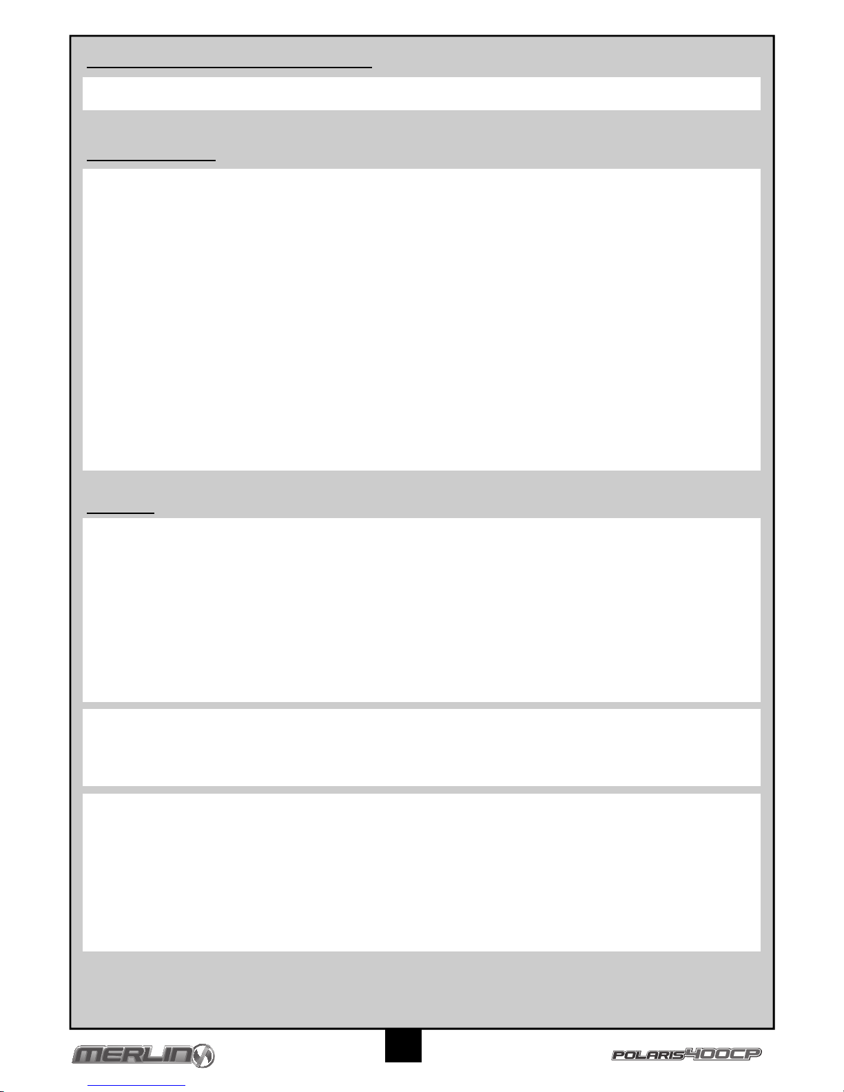
Specification
Glossary
Landing gear - Legs on the underside of helicopter.
Rotor - High speed rotating blades used to lift the helicopter into the air.
Throttle - A control function to adjust the speed of the rotating blades & height of the helicopter.
Rudder - A control function to turn the helicopter.
Cyclic Controls - Control functions to move the helicopter in flight.
Fuselage - Main body of the helicopter containing motor, receiver, speed control, servos and battery
Gyro - An electronic stabiliser built into the helicopter to assist flight.
LED - A coloured indicator light.
Swash Plate - Rotating plate below the rotor that adjusts the blade angles.
Safety Precautions
• Read and follow this manual completely, observing all instructions and safety directions. Otherwise, serious injury and damage can occur.
Think about your safety, and the safety of others, first.
• Hold the product securely when the flight battery is plugged in, keep the rotor away from body parts and clothing, even it isn’ t spinning, as
it could be turned on by accident. Beware of hair becoming entangled in the rotor.
• Do not fly when it’s too windy or you may lose control and crash, causing injury or damage. Never fly near people, vehicles, train tracks,
buildings, power lines, water, hard surfaces or trees. Never allow anyone to attempt to catch the model while it’s in flight or serious injury
may result.
• Adult supervision for flying and battery charging is recommended for pilots age 14 and younger.
• Only use a battery charger that is compatible with the flight battery. Never leave the charger unattended while charging. This will help
prevent overcharging and make sure damage does not occur to the battery, charger or any other property. While charging, place the
battery on a heat-resistant surface. Do not lay it on carpet or upholstery while charging.
• Never cut into the battery, charger, or aeroplane wires or serious injury may occur. Causing the battery to “short out” (crossing negative
and positive bare wires) can cause fire, serious injury and damage.
• When you finish flying your product, always unplug the battery before you turn off the transmitter.
• Always check that the transmitter has full control of the helicopter before flying.
Charging the battery pack
Use the supplied charger to charge the supplied battery. Other products are available and if used, you must follow the products instructions to
avoid damage.
The typical charge time for a flat battery is 140 minutes.
1. Connect the 240V wall mounted transformer (12V output) to the input side of the supplied charger, the red power indicator should glow.
2. Plug the battery into the 11.1V 3-cell output socket of the charger. The charge indicator should glow red to indicate charging is taking
place.
3. When charging is complete the charger will automatically stop charging and the charge indicator will glow green.
4. Unplug the battery and input to the charger.
Cautions
• Use the charger with adult supervision. Do not use the charger near water or when wet.
• Do not use the charger if the wire is frayed or worn. If the wire is frayed or worn a short circuit can cause a fire or burns.
• If your battery gets hot and exceeds 50 degrees C during charge it may be faulty and you should contact your retailer
• If the battery pack bulges or expands during charge or use it is faulty and you should contact your retailer.
• Never leave your battery pack on charge unattended.
Main Rotor Diameter 550mm
Fuselage Length 580mm
Flying Weight 438g
Motor 380 Size Brushed
Battery 11.4V 950 mAh Li-Po Battery
Transmitter MTX-442 2.4 GHz 4 Channel
Receiver MRX-442 2.4 Ghz 6 Channel
Servos 3 x 9g Micro Servos
Charger Mains 240V / 12.6V 500mAh
Page 4
3
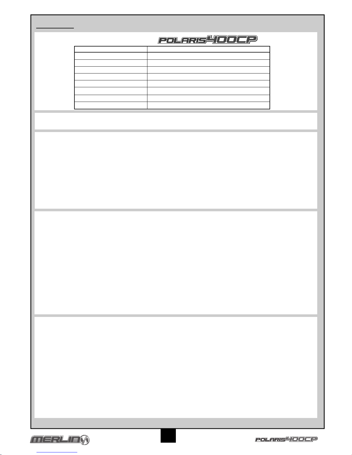
Transmitter
Your Merlin Transmitter is an advanced controller designed for the beginner to be easy to use and tune. You will need to follow the steps below to
ensure you prepare the controller correctly for use and understand the adjustment possibilities available.
Transmitter Controls
Binding the transmitter to the model.
1. Switch on the transmitter, ensuring that the throttle control stick at its lowest position.
2. Connect the receiver battery to the receiver and wait until the Power Indicator LED on the receiver glows solid green.
3. Press and hold the Binding Button on the receiver for approximately 2 seconds until the Binding Indicator LED on the receiver goes solid
green, indicating the binding finished.
Preparing the transmitter
Make sure the aerial on the
transmitter is fully upright before
switching the transmitter on.
Open the battery holding tray to
expose the empty battery slots.
Insert 4 AA batteries into the
marked spaces. Please note the
correct direction of the batteries.
Incorrect battery insertion could
lead to damage.
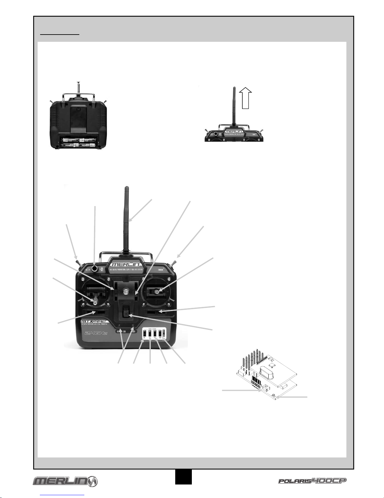
1. Aerial
2. Throttle Trim
3. Cyclic L/R Trim
4. Cyclic F/B Trim
5. Throttle Stick
6. Cyclic Control Stick
7. Power Switch
8. Battery level indicator
9. Rudder reverse switch
10. Aileron reverse switch
11. Throttle reverse switch
12. Elevator reverse switch
13. Rudder Trim
14. Idle up switch
15. Training switch
16. Dual Rate
17. Binding Button
18. LED
18
17
1
4
2
3
5
6
10
8 12 11
9
13
7
14
15
16
Page 5
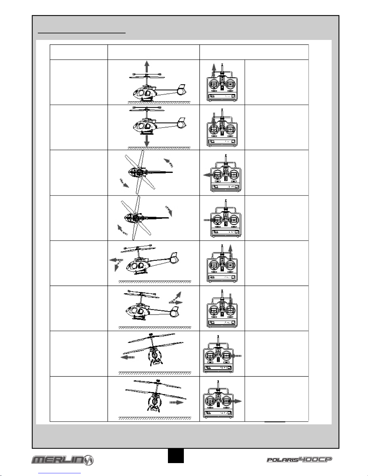
4
Main body lifts up
Main body lowers
The nose will turn to
the left
The nose will turn to
the right
The nose will dive
and move forwards
The nose will raise
and move back-
wards
The body will pitch
to the left
The body will pitch
to the right
Push throttle stick
forwards
Pull throttle stick
backwards
Push the rudder stick
to the left
(Move trim lever to
right)
Push the rudder stick
to the right
(Move trim lever to
left)
Push the cyclic control
stick forwards
(Move trim lever back-
wards)
Pull the cyclic control
stick backwards
(Move trim lever
forwards)
Push the cyclic control
stick to the left
(Move trim lever right)
Push the cyclic control
stick to the right
(Move trim lever left)
Actions Transmitter & (Trimming ) Input
Controlling your Helicopter
Page 6
5
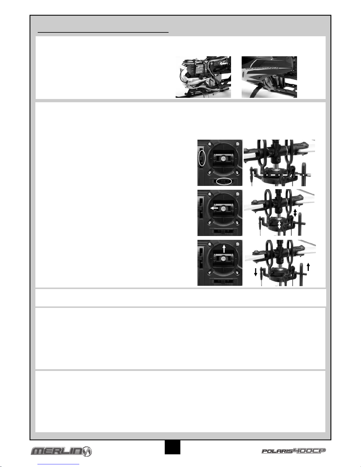
Trimming Adjustments and Control Tests
Switching Off
Unplug the helicopter battery followed by switching off the transmitter. Always follow this procedure when switching off.
Installing the blades
Installing the battery
Checklist
Each time before you start flying your Merlin Flight Product, please carry out the following checks and tests.
• Make sure the Swash plate has free movement
• All screws, bolts, etc. are tight
• Radio equipment is securely fastened inside fuselage
• Batteries are fully charged.
• No wires interfere with servo motors
• Blades are securely fastened
Control Test
• Be certain that the throttle stick is in the “off” position.
• Switch on the transmitter, make sure the aerial is upright and check to make sure the Power LE Ds are lit indicating the transmitter has
power. If only the red LEDs are lit then the transmitter batteries are low on power and must be replaced before flying.
• Plug in the helicopter battery and wait for the receiver power light to stop flashing to confirm the unit has calibrated.
• Place your model on the ground and walk away whilst operating the swash plate controls.
• Check that the servos operate without interference up to a distance of 30 metres.
• Gently move the throttle stick forwards to check the main blades rotate.
To install the Li-PO battery into the fuselage insert the
charged battery into the bottom of the helicopter base.
Attach a rubber band around the battery and locate on the
canopy mounting bar. Then attach the canopy.
3. The helicopter swash plate should be horizontal
when viewed from the front and from the side of the
helicopter. If it is not, adjust it’s position by operating the
cyclic trims on the transmitter.
4. Move the cyclic control stick to the left and the swash plate
will tilt in the indicated direction in the picture.
5. Move the cyclic control stick forwards and the swash plate
will tilt as indicated in the picture.
1. Switch on your transmitter and make sure the throttle stick is fully pulled back.
2. Make sure the battery is plugged in. Leave the helicopter until you see the power light stop flashing and remain constant to confirm
the unit has calibrated.
Trimming Check
Please refer to replacing the blades section on Page 7. Please note the direction of the blades, they need to match the pitch of the Flybar
Paddles.
Page 7
6
How to Fly
Learning to Hover
1. Place your helicopter in a an open space facing away from yourself about 5 metres in distance.
2. Push the throttle stick gently forwards increasing the blade speed until it becomes light just lifting from the ground.
3. Gently decrease the power to land smoothly.
4. If your helicopter moves away from the centre of your training area place it back in the middle.
5. Repeat this exercise increasing the flying height of 1 metre can be achieved whilst remaining in control.
All helicopters experience some instability immediately on lifting from the ground. If this does not stabilise as height is gained and your helicopter
drifts or turns repeatedly in one direction you will need to adjust the transmitter trim levers. To do this refer to Controlling Your Helicopter and
move the transmitter trim lever one or two clicks in the opposite direction to the travel until a steady hover is achieved.
Experience
Your Tracer helicopter makes an ideal introduction to flying RC Helicopters and by following the following basic instructions inexperienced pilots
should soon master basic flying skills.
Learning to Turn
1. Hover your helicopter 1 metre in the air.
2. Move the rudder stick a small amount in one direction and release it. The tail of your helicopter will swing around and stop in the new
position.
3. Repeat applications of rudder so you can turn and hover facing in any chosen direction.
Site & Conditions
• Fly your helicopter indoors in a large room, hall or office. Only fly outdoors in perfectly calm conditions with no wind unless you are an
experienced pilot.
• Make sure there are no obstacles that will get in your way when flying, such as furniture, trees or buildings.
• Make sure you do not fly where there are people or animals who could be hurt by the helicopter.
• If flying outdoors position yourself so that you keep the sun at your back and out of your eyes. Wear sunglasses on bright days.
• Keep your helicopter in front of you so you don’t have to turn in circles as you fly. Try to avoid flying directly overhead.
Learning Forward and Backwards Flight
1. Hover your helicopter 1 metre in the air.
2. Move the cyclic control stick forwards gently and release it, your helicopter will move forwards then hover stationary.
3. Reduce the throttle stick and land your helicopter returning it to its starting position.
4. Repeat this exercise but prior to landing move the cyclic stick back to return the helicopter to its starting position whilst in flight.
Learning Sideways Flight
1. Hover your helicopter 1 metre in the air.
2. Move the cyclic control stick sideways gently and release it, your helicopter will move sideways then hover stationary.
3. Reduce the throttle stick and land your helicopter returning it to its starting position.
4. Repeat this exercise but prior to landing move the cyclic stick back to return the helicopter to its starting position whilst in flight.
Combining Controls
1. Hover your helicopter 1 metre in the air.
2. Move the cyclic stick forwards and hold its position to achieve a slow forward flight.
3. Move the rudder stick left or right and your helicopter will begin to fly in a circular motion.
4. Practice turning left and right circles of small and large diameters.
By combining control inputs you will be able to control your helicopter position accurately and fly in more advanced patterns such as figure of eight
or carry out simple aerobatic manoeuvres.
Once confidence and control has been gained experiment by increasing the hovering height to 2 to 3 metres and combining forwards, backwards,
sideways and turn controls.
Tips for Success
• Only operate the throttle stick gently with small inputs, the most common form of damage is due to reducing the throttle by large amounts
causing sudden reductions in height and crashing.
• When your helicopter begins to climb slowly or is unable to climb on full throttle then the battery is beginning to run low, for safety land
your model as soon as possible and re-charge.
• Damage or bends to the blades or fuselage can greatly affect flight control. Replace damaged parts immediately.
• Don’t attempt to fly or do manoeuvres beyond your flying abilities.
Page 8
7
Problem Cause Solution
Unit does not operate Transmitter “AA” batteries are depleted or
installed incorrectly, indicated by a dim or
unlit LED on transmitter or the low battery
alarm.
Check polarity installation or replace with
fresh “AA” batteries.
No electrical connection. Push connectors together until they “click.”
Main motor does not turn 4-in-1 unit not operating correctly Consult your retailer
Helicopter spins uncontrollably Gyro gain is incorrectly setup Adjust Gyro gain to 90%
Helicopter will not hover still when sticks
are neutral
Trimming incorrect or swash plate is not
level
Adjust trim levers or adjust Swash plate
Vibration Bent main shaft Replace main shaft
Blades are broken Replace blades
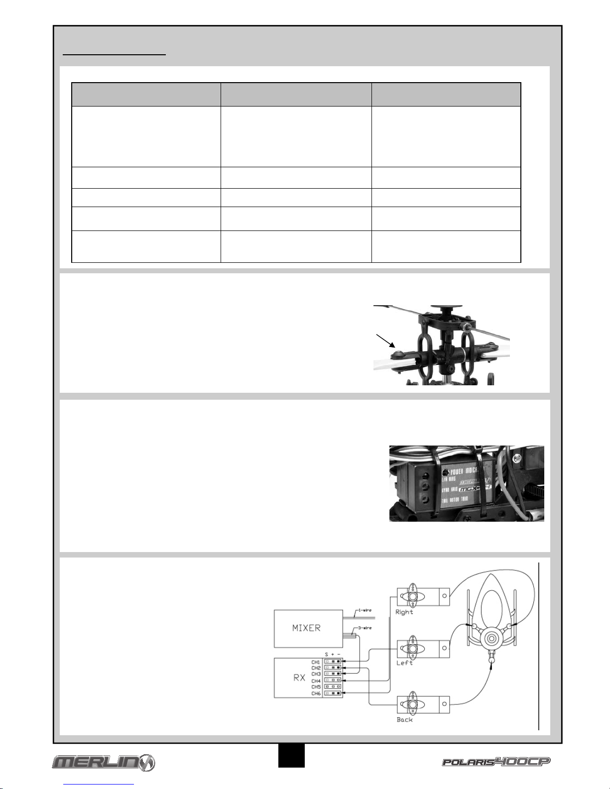
Troubleshooting
Helpful Information
Replacing the Blades
Your Tracer helicopter is supplied with a spare set of replacement blades in the event of crash damage. Should you need to replace the blades
please follow these simple steps :-
Fine Tuning of YAW Control
The controls are pre set in the manufacture and test flying of your helicopter and should not need adjustment. However for tuning by experienced
pilots or in the event of a serious crash and the need to re-build your helicopter their adjustment and function is as follows :-
Tail Rotor Trim – If the helicopter wants to drift one direction in a stable hover then try using this adjustment .The adjustment is very sensitive so
only make small changes. Turn clockwise to add right tail rotor trim.
1. The blades are fastened with a screw and can be removed very easily
2. Loosen the screw on the damaged blade and remove it allowing the
blade to come off
3. Insert the new blade into the gap noting the direction and pitch of the
Flybar Paddles and replace the screw tightening only sufficient to make
sure the blade still moves freely.
Left/Right Bias – Is used to obtain a balanced feel between left and right tail rotor inputs. The
adjustment is very sensitive so only make small changes. Turn clockwise to increase the left tail
rotor bias.
Gyro Gain – Turn clockwise to increase gain. Typically too little gyro gain causes the tail to
slowly move around and drift. With the gyro gain too high, you will notice a very fast oscillation in
the tail known as “wag.” This adjustment is not very critical so please don’t spend a lot of time
trying to get “the best” setting possible.
Receiver and Servo Wiring
Under normal circumstances there should be no need to
unplug any of your receiver wiring, however for reference
purposes the receiver is wired as follows.
Page 9
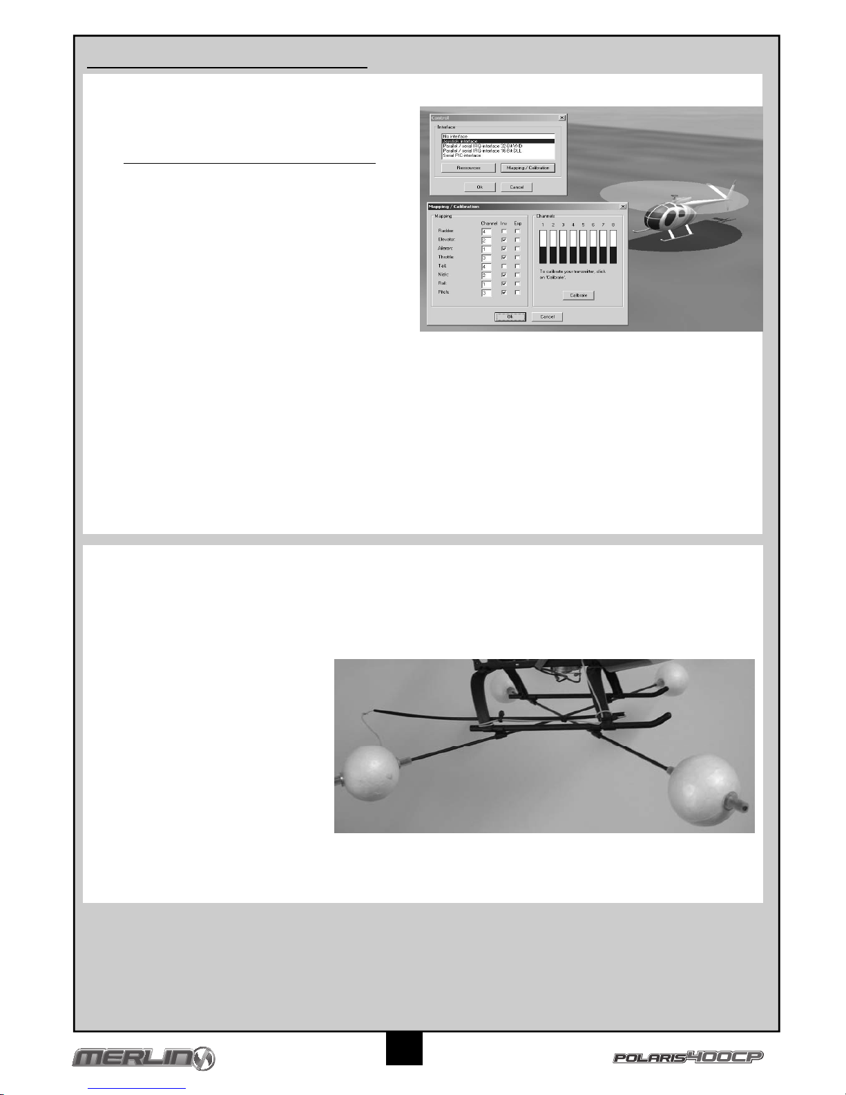
Your Merlin helicopter transmitter comes supplied with a USB adaptor cable to enable it to link to a Windows PC and run freeware FMS simulation
software.
Downloading
1. Visit website
http://n-old.ethz.ch/student/mmoeller/fms/index_e.html
or use a
search engine search for “flying model simulator + FMS”
2. Download and run the software for your PC following the
instructions given on the website.
Setting your Transmitter
Please use the following settings when setting up your FMS software
1. Switch on your transmitter and connect it to your PC with the
USB cable.
2. Select Model and load Hughes from the pull down menu.
3. Select Controls and Analogue Controls from the menu.
4. Select Mapping and Calibration.
5. Move each control stick noting which channel is operated,
ensure that the channel number operated is set to the correct
control function (Mapping) as above.
6. Select Calibrate, move the controls fully in all directions, select next & finish.
7. Check that each control operates in the desired direction by selecting Simulation and Initialise moving each control in turn to see if the
helicopter moves in the expected direction. If control surfaces do not operate correctly then adjust the control numbers & Inv to reverse
the function to achieve the correct directions.
Training
Select Simulation & Initialise then follow the instructions given in the Learning to Fly part of your manual.
For inexperienced pilots selecting View and ticking Auto zoom and Simulation / Options ticking Model Un crashable will help learning basic skills.
For more advanced pilots the FMS software simulator can be adjusted to change models (Model) to include aeroplanes, flying sites (Landscape)
and screen view (View) by experimenting with the menus.
8
Using your Flying Simulator Freeware
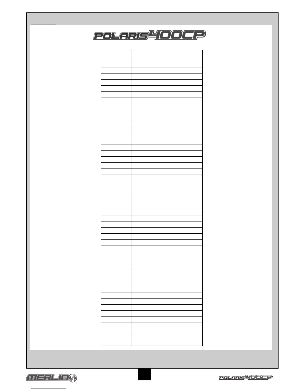
Training Skid Option
Your Polaris 400CP has been supplied with a set of optional training skids to help take-off and landing stability for new pilots whilst learning to fly.
These should be assembled as below.
Clip the rod guides onto the undercarriage
Push the rod through the rod guides until they are
of equal distance both sides from the
undercarriage
Cut the rubber tubing into 8 pcs of equal length.
Slide 1 piece of tube over the rod leaving about
50mm spacing to the end of the rod
Cut the rubber tubing into 8 pcs of equal length.
Slide 1 piece of tube over the rod leaving about
50mm spacing to the end of the rod.
Slide 1 washer onto the rod followed by a foam
ball, washer and the tube to secure it into place.
Make sure the ball can rotate freely on the rod.
Repeat this until all 4 balls are installed
Page 10
9
Parts List
Part Number Description
ML44001 Center Hub
ML44002 Head Button
ML44003 Slide Block And Seesaw
ML44004 Flybar Carrier
ML44005 Main Rotor Blade Grips
ML44006 Flybar Link
ML44007 Main Rotor Link
ML44008 Flybar Paddles
ML44009 Swashplate Assembly
ML44010 Pushrod
ML44011 Flybar
ML44012 Feathering Spindle
ML44013 Upper Main Frame
ML44014 Swashplate Stay
ML44015 Lower Main Frame
ML44016 Support Strut
ML44017 Tail Boom
ML44018 Main Shaft
ML44019 Canopy
ML44020 Screw Set
ML44021 Skid Support
ML44022 Landing Skids
ML44023 Washer Set
ML44024 O-Ring Set
ML44025 Main Rotor Gear
ML44026 Main Shaft Collar And Bushing
ML44027 Tail Motor Mount
ML44028 Main Motor 380
ML44029 Main Rotor Blades
ML44030 Motor Heatsink
ML44031 Tail Motor
ML44032 Training Gear
ML44033 Tail Vertical Fin
ML44034 Tail Shaft
ML44035 Tail Rotor Gear
ML44036 Tail Rotor Blade
ML44037 Feathering Bearings
ML44038 Tail Rotor Bearing
ML44039 Main Frame Bearing
ML44040 Tail Motor Wire
ML44041 Servo
ML44042 Lipo Battery
ML44045 Charger (UK 3 Pin)
ML44046 Charger (EU 2-Pin)
ML44048 Polaris 400CP Instruction & Parts manual
ML44049 Aerial Tube
ML44050 Silcon Tube
ML44070 E-Board 2.4 GHz (Polaris 400CP)
ML44071 Receiver 2.4 GHz (Polaris 400CP)
ML44072 Transmitter 2.4 GHz (Polaris 400CP)
Page 11
AMUSEZ-VOUS ! Mais lisez ceci d’abord !!
Nous savons que vous allez bien vous amuser avec votre modèle, mais pour obtenir le meilleur de votre achat, veuillez lire cette information
AVANT de le mettre en marche
10
Page
Garantie 10
Introduction 11
Éléments obligatoires pour le fonctionnement 11
Glossaire 11
Mesures de sécurité 11
Charge de la batterie 11
Émetteu 12
Contrôle de votre hélicoptère 13
Réglages de compensation et Essais de contrôle 14
Comment voler ? 15
Dépannage 16
Remplacement des Pales 16
Réglage précis du Contrôle en lacet 16
Utilisation du Simulateur de vol Gratuit 17
Parts List Polaris 400CP 18
Dessin éclaté Polaris 400CP 37
Garantie
Garantie du composant de 90 jours
Ce produit est couvert par une garantie composant de 90 jours à partir de la date d’achat. Si, pendant cette période, l’une des pièces du produit a
un défaut de fabrication, nous la réparerons ou la remplacerons à notre choix.
Nous ne donnerons pas de nouvelle garantie pour une ancienne, une fois que le produit a été utilisé.
Veuillez remarquer que ce produit n’est pas un jouet, et qu’il est recommandé aux moins de 14 ans sous la surveillance d’un adulte. Il est de la
responsabilité des parents ou tuteur de garantir que les mineurs ont l’aide et la supervision nécessaires,
Si vous pensez qu’il existe, pour toute raison, un problème avec le produit, il est de la responsabilité de l’utilisateur de rechercher et de suivre les
pas afin de corriger le problème avant de causer de plus grands dommages.
Non couvert par la garantie
Ceci est un modèle sophistiqué et de haute performance et devra être traité avec soin et respect. Tous les efforts ont été faits pour rendre ce
produit aussi fort et durable que possible, toutefois, il est possible de casser ou d’endommager des pièces après un choc ou un usage ext rême.
Les composants endommagés suite à une collision, un usage incorrect, un manque d’entretien ou des mauvais traitements ne sont pas couverts
par la garantie.
Comment revendiquer votre garantie
Pour les droits de garantie, veuillez prendre d’abord contact avec votre fournisseur. Ne renvoyez pas le produit à votre distributeur sans leur
accord préalable. Vous n’avez pas à renvoyer le produit en entier, mais seulement le composant endommagé avec une copie de votre bon
d’achat. Dans beaucoup de cas, il est plus rapide et rentable pour l’usager de monter le(s) pièce(s) de rechange sur le produit et dans ce cas,
nous nous réservons le droit de ne fournir des pièces que dans ce cas.
Tout composant retourné et inspecté par notre distributeur ne possédant pas une garantie valable, peut être sujet à des frais d’inspection et de
manipulation avant sa réexpédition. Toutes les réparations nécessaires suite à une négligence ou mauvaise utilisation seront facturées avant le
début de tout travail sur le produit. Si vous décidez de ne réaliser aucun travail, le distributeur se réserve le droit de facturer des frais de
manipulation et d’expédition.
Veuillez joindre votre preuve d’achat à ce manuel car vous pourrez en avoir besoin à l’avenir.
Sommaire
Page 12
Éléments obligatoires pour le fonctionnement
4 * piles AA pour l’émetteur
11
Introduction
Spécifications
Glossaire
Train d’atterrissage - Jambes sous l’hélicoptère.
Rotor - Pales de rotation très rapide utilisées pour élever l’hélicoptère dans l’air.
Accélération - Fonction de contrôle pour régler la vitesse de rotation des pales et la hauteur de l’hélicoptère.
Gouvernail - Fonction de contrôle pour faire virer l’hélicoptère.
Manche cyclique - Fonctions de contrôle pour déplacer l’hélicoptère en vol.
Fuselage – Corps principal de l’hélicoptère qui contient le moteur, le récepteur, le contrôle de vitesse, les servos et la batterie.
Gyro – Stabilisateur électronique incorporé à l’hélicoptère pour faciliter le vol.
Del – Voyant lumineux de couleur.
Plateau cyclique – Pale rotative sous le rotor qui ajuste les pas cycliques.
Mesures de sécurité
•
Lisez et suivez complètement ce manuel, en respectant toutes les instructions et les conseils de sécurité. Dans le cas contraire, de
graves blessures et dommages peuvent se produire. Pensez à votre sécurité, et d’abord à la sécurité des autres.
• Maintenez le produit protégé lorsque la batterie de vol est branchée ; gardez l’hélice loin des pièces du corps et des vêtements, même si
elle ne tourne pas vite, car cela peut provoquer un accident. Faites attention de ne pas entremêler les cheveux dans l’hélice, surtout lors
du lancement de votre modèle.
• Ne volez pas s’il y a trop de vent ou vous pourrez perdre le contrôler et collisionner provoquant des blessures ou des dégâts. Ne volez
jamais près de personnes, véhicules, voies ferrées, bâtiments, lignes électriques, eau, surfaces dures ou arbres. Ne permettez jamais
que quelqu’un n’essaye d’attraper le modèle en vol : cela pourrait provoquer de graves blessures.
• La supervision d’un adulte est recommandée lors du vol et du chargement de la batterie pour les pilotes de moins de 14 ans.
• N’utilisez qu’un chargeur de batterie compatible avec la batterie de vol. Ne laissez jamais le chargeur sans surveillance lors du
chargement. Cela peut éviter la surcharge et que des dégâts ne se produisent sur la batterie, le chargeur ou toute autre propriété.
Pendant le chargement, posez la batterie sur une surface résistante à la chaleur. Ne la laissez pas sur un tapis ou un tissu pendant le
chargement.
• Ne jamais toucher la batterie, le chargeur ou les câbles ou de graves blessures peuvent se produire. Avec le court-circuit de la batterie
(en croisant les fils nus positif et négatif), on peut provoquer un incendie, une blessure grave et des dommages.
• Quand vous avez fini de faire voler le produit, débranchez toujours la batterie avant d’éteindre l’émetteur.
• N’utilisez jamais le produit sur la même fréquence qu’un autre modèle radiocommandé dans votre zone. La fréquence du modèle est
indiquée sur les éléments piézoélectriques de fréquence.
Charge de la batterie
Utilisez le chargeur fourni pour charger la batterie fournie. D’autres produits sont disponibles et si vous les utilisez, vous devez suivre les
instructions des produits pour éviter des dommages.
La durée de chargement de la batterie est de 140 minutes
1. Branchez le chargeur de la batterie à une prise de CA. Le Del du charger s’allume en vert.
2. Branchez la batterie au chargeur. Le Del du chargeur devient rouge, indiquant ainsi que le chargement est en cours.
3. Le chargement est fini lorsque le voyant Del est vert. Lorsque le chargement arrive à sa fin, la batterie devient chaude.
4. Débranchez la batterie et l’entrée du chargeur.
Attention
• Utilisez le chargeur sous la supervision d’un adulte. N’utilisez pas le chargeur près de l’eau ou s’il est mouillé.
• N’utilisez pas le chargeur si le câble est effiloché ou usé. Si le câble est effiloché ou usé, un court-circuit peut provoquer un
incendieou des flammes.
• Si votre batterie devient chaude et dépasse les 50 degrés C pendant le chargement, elle peu défaillir et vous devrez contacter votre
détaillant.
• Si la batterie gonfle ou s’étend pendant le chargement ou son utilisation, c’est qu’elle est défectueuse et vous devrez contacter votre
détaillant.
Diamètre rotor principal 550mm
Longueur Fuselage 580mm
Poids 438g
Moteur Brushed taille 380
Batterie 11.1V 950 mAh Li-Po
Transmetteur MTX-442 2.4 GHz 4 canal
Récepteur MRX-442 2.4 GHz 6 canal
Servos 3 x 9g Servos micro
Régulateur de vitesse électronique Principaux 240V / 12.6V 500mAh
Page 13

12
Émetteu
Votre émetteur Merlin est un régulateur avancé conçu pour faciliter l’utilisation et le réglage pour le débutant. Vous devrez suivre les étapes
ci-dessous pour vous assurer que vous avez préparé correctement le régulateur et que vous avez compris les possibilités disponibles de réglage.
Commandes
Lier l'émetteur au modèle.
1. Mettez l'émetteur sous tension en veillant à ce que la commande de gaz soit en position minimale.
2. Reliez la batterie du récepteur au récepteur et attendez que le témoin à DEL d'alimentation du récepteur émette une lumière verte
permanente.
3. Sur le récepteur, appuyez pendant environ 2 secondes, sur le bouton d'association, le temps pour que le témoin à DEL d'association
émette une lumière verte permanente, ce qui signale l'achèvement de l'opération d'association.
Préparation de l’émetteur
Ouvrez la plaque de retenue des
piles pour découvrir les fentes des
piles vides.
Insérez 4 piles AA dans les
espaces marqués à cet effet.
Veuillez faire attention au sens
correct des piles
L’insertion incorrecte des piles
peut provoquer des dommages
Insérez l’antenne dans le trou
et tournez-la à droite jusqu’à
ce qu’elle soit bien fixe.
17
18
1. Antenne
2. Compensateur d’accélération
3. Compensateur cyclique D/G
4. Compensateur cyclique Avt/ Arr.
5. Manette d’accélération
6. Manette du manche cyclique
7. Interrupteur
8. Indicateur de niveau des piles
9. Commande de Gouvernail inverse
10. Commande de aileron inverse
11. Commande d’accélération inverse
12. Commande de gouverne de profondeur
inverse
13. Compensateur de la direction
14. Commutateur de ralenti
15. Commutateur d’entraînement
16. Double taux
17. Bouton d'association
18. DEL
1
4
2
3
5
6
10
8 12 11
9
13
7
14
15
16
Page 14

13
Le corps principal
s’élève
Le corps principal
descend
Le nez vire vers la
gauche
Le nez vire vers la
droite
Le nez piquera et
ira vers l’avant
Le nez s’élèvera et
ira vers l’arrière
Le corps tangue
vers la gauche
Le corps tangue
vers la droite
Poussez la manette
d’accélération vers
l’avant
Poussez la manette
d’accélération vers
l’arrière
Poussez la manette du
gouvernail vers la
gauche
(Bougez le levier de
compensation à droite)
Poussez la manette du
gouvernail vers la
droite
(Bougez le levier de
compensation à
gauche)
Poussez la manette de
manche cyclique vers
l’avant
(Bougez le levier de
compensation vers
l’arrière)
Poussez la manette de
manche cyclique vers
l’arrière
(Bougez le levier de
compensation vers
l’avant)
Poussez la manette du
manche cyclique vers
la gauche
(Bougez le levier de
compensation à droite)
Poussez la manette du
manche cyclique vers
la droite
(Bougez le levier de
compensation à
gauche)
Actions Émetteur et Ordre (compensation)
Contrôle de votre hélicoptère
Page 15

14
Réglages de compensation et Essais de contrôle
Arrêt
Débranchez la batterie de l’hélicoptère suivi par l’arrêt de l’émetteur. Suivez cette procédure pour l’arrêt.
Pose des pales
Installation de la batterie
Pour monter la batterie Li-PO dans le fuselage, introduisez la
batterie chargée dans la base de l'hélicoptère. Fixez un
caoutchouc autour de la batterie puis autour de la tige de
fixation de la cabine. Fixez ensuite la cabine.
Liste de verification
Avant chaque vol de votre produit d’aviation Merlin, veuillez réaliser les vérifications et essais suivants.
• Vérifiez que le plateau cyclique possède un mouvement libre.
• Toutes les fixations comme les vis et boulons sont serrées
• L’équipement radio est fermement fixé dans le fuselage
• Les batteries sont complètement chargées.
• Aucun fil ne gêne les moteurs de servo
• L’antenne est correctement étendue
• Les pales sont bien attachées
Essai de contrôle
1. Soyez sûr que la manette d’accélération est sur la position « off »
2. Allumez l’émetteur et vérifiez que le voyant Del soit allumé, indiquant que l’émetteur reçoit son alimentation. Si les batteries de l’émetteur
sont faibles, elles peuvent être remplacées avant le vol.
3. Branchez la batterie de l’hélicoptère et attendez 5 secondes pour que la lumière d’alimentation du récepteur arrête de clign oter afin de
confirmer que l’unité est calibrée.
4. Posez votre modèle au sol et éloignez-vous tout en faisant fonctionner les commandes du plateau cyclique.
5. Vérifiez que les servos fonctionnent sans interférence sur une distance de 30 mètres.
6. Bougez doucement la manette d’accélération vers l’avant pour vérifier que les pales principales tournent.
3. Le plateau cyclique de l’hélicoptère doit être horizontal vu de
face et de côté de l’hélicoptère. Dans le cas contraire,
ajustez sa position en faisant marcher les compensateurs
cycliques de l’émetteur.
4. Bougez la manette du manche cyclique vers la gauche et le
plateau cyclique s’inclinera dans la direction indiquée du
dessin.
5. Bougez la manette du manche cyclique vers l’avant et le
plateau cyclique s’inclinera dans la direction indiquée du
dessin.
1. Allumez votre émetteur et vérifiez que la manette d’accélération est complètement tirée vers l’arrière.
2. Vérifiez que la batterie est branchée. Laissez l’hélicoptère jusqu’à voir la lumière d’alimentation arrêter de clignoter et qu’elle reste
stable afin de confirmer que l’unité soit calibrée.
Vérification de la compensation
Veuillez vous reporter à la section Remplacement des pales, page 16. Veuillez noter que les pales ont un sens et que vous devez tenir
compte de l'inclinaison des palettes d'arbre.
Page 16

15
Apprentissage du Vol stationnaire
1. Placez votre hélicoptère dans un espace ouvert face à vous à environ 5 mètres de distance.
2. Poussez la manette d’accélération vers l’avant en augmentant la vitesse des pales jusqu’à ce qu’il décolle légèrement du sol.
3. Diminuez délicatement la puissance pour atterrir en douceur.
4. Si votre hélicoptère s’éloigne de trop du centre de votre aire d’entraînement, reposez-le au milieu.
5. Répétez cet exercice en augmentant la hauteur de vol de 1 mètre peut être effectué tout en gardant le contrôle.
Tous les hélicoptères expérimentent une certaine instabilité immédiatement après le décollage. S’il ne se stabilise pas en prenant de la hauteur et
qu’il dérive ou tourne répétitivement dans un sens, vous devrez régler les leviers de compensation de l’émetteur. Pour faire cela, reportez-vous à
Contrôle de votre hélicoptère et bougez le levier de compensation de l’émetteur d’un ou deux clics dans le sens opposé à la trajectoire jusqu’à
l’obtention d’un vol stationnaire.
Expérience
Votre hélicoptère Pulsar est une introduction parfaite aux hélicoptères radiocommandés et si les pilotes sans expérience suivent les instructions
de base suivantes, ils maîtriseront bientôt les habiletés de vol fondamentales. Si vous possédez un ordinateur avec un accès Internet, téléchargez
et suivez la partie d’entraînement du simulateur de Gestion de Vol avant de faire voler votre modèle. Cela aidera les nouveaux pilotes à se
familiariser avec les commandes.
Apprentissage du virage
1. Gardez votre hélicoptère en vol stationnaire à 1 mètre dans l’air.
2. Bougez un peu la manette du gouvernail dans un sens puis relâchez-la. La queue de votre hélicoptère tourne et s’arrête dans une
nouvelle position.
3. Répétez les applications du gouvernail pour que vous puissiez virer et réalisez un vol stationnaire dans le sens souhaité.
Endroit et conditions
• Faites voler votre hélicoptère en intérieur dans une grande pièce, un vestibule ou un bureau. Ne volez en extérieur que si des conditions
de calme totale sans aucun vent se présentent, à moins d’être un pilote expérimenté.
• Vérifiez l’absence de tout obstacle sur votre chemin lors du vol, comme des meubles, des arbres ou des bâtiments.
• Vérifiez que vous ne volez pas où se trouvent des personnes ou des animaux, qui pourraient être blessés par l’hélicoptère.
• Si vous volez en extérieur, placez-vous sur de manière à garder le soleil à votre dos et loin de votre vue. Portez des lunettes de soleil, les
jours lumineux.
• Gardez votre hélicoptère devant vous pour ne pas avoir à tourner en rond lors du vol. Essayez d’éviter de voler directement au dessus de
votre tête.
Apprentissage de vol en avant et en arrière
1. Gardez votre hélicoptère en vol stationnaire à 1 mètre dans l’air.
2. Bougez délicatement la manette de manche cyclique vers l’avant et relâchez-la, votre hélicoptère se déplacera vers l’avant puis restera
stationnaire.
3. Réduisez la manette d’accélération et faites atterrir votre hélicoptère en le faisant revenir à sa position de départ.
4. Répétez cet exercice mais avant d’atterrir, bougez la manette cyclique vers l’arrière pour faire revenir l’hélicoptère à sa position de départ
tant qu’il est en vol.
Comment voler ?
Trucs pour réussir
• Ne faites marcher la manette d’accélération délicatement avec de petits coups, la manière la plus commune de causer des dégâts se doit
à la réduction de l’accélération par de grands coups ce qui provoque des réductions soudaines de hauteur et donc une collision.
• Si votre hélicoptère commence à s’élever lentement ou ne peut s’élever avec l’accélération à fond, c’est que la batterie s’affaiblit, pour des
raisons de sécurité, faites atterrir votre modèle le plus tôt possible et rechargez la batterie.
• Les dommages /fléchissements des pales ou du fuselage peuvent beaucoup affecter le contrôle du vol. Remplacez les pièces
endommagées immédiatement.
• N’essayez pas de voler ou de manœuvrer au dessus de vos possibilités de vol.
Apprentissage du vol en biais
1. Gardez votre hélicoptère en vol stationnaire à 1 mètre dans l’air.
2. Bougez délicatement la manette de manche cyclique vers le côté et relâchez-la, votre hélicoptère se déplacera vers ce côté puis restera
stationnaire.
3. Réduisez la manette d’accélération et faites atterrir votre hélicoptère en le faisant revenir à sa position de départ.
4. Répétez cet exercice mais avant d’atterrir, bougez la manette cyclique vers l’arrière pour faire revenir l’hélicoptère à sa position de départ
tant qu’il est en vol.
Combinaison des commandes
1. Gardez votre hélicoptère en vol stationnaire à 1 mètre dans l’air.
2. Bougez la manette cyclique vers l’avant et gardez sa position afin d’obtenir un vol lent vers l’avant.
3. Bougez la manette du gouvernail à gauche ou à droite et votre hélicoptère commencera à voler dans un mouvement circulaire.
4. Exercez-vous en faisant des cercles sur la droite et sur la gauche de diamètres variés.
En combinant les ordres de contrôle, vous serez capable de contrôler la position de l’hélicoptère avec précision et de voler selon des schémas
plus complexes comme la figure du huit ou simplement pour réaliser des manœuvres acrobatiques.
En gagnant de la confiance et plus de contrôle, expérimentez en augmentant la hauteur du vol stationnaire à 2-3 mètres et en combinant les
commandes avant, arrière, de côté et virage.
Page 17

16
Remplacement des Pales
Votre hélicoptère Pulsar est fourni avec un jeu de secours de pales de rechange en cas de dommage suite à une collision. Si vous devez
remplacer les pales, veuillez suivre ces étapes simples
Réglage précis du Contrôle en lacet
Les contrôles sont prédéfinis en usine et votre hélicoptère testé en vol : il n’y a donc pas besoin de réglage. Toutefois pour un réglage par des
pilotes expérimentés ou en cas de grave collision, et donc de reconstruction de votre hélicoptère, les réglage et fonction sont comme suit :
Compensation du rotor de queue – Si l'hélicoptère a tendance à dériver dans un sens alors qu'il est en vol stationnaire, tentez un réglage de
cette commande. Le réglage est très sensible, donc procédez par petites étapes. Tournez dans le sens des aiguilles d'une montre pour la
compensation à droite du rotor de queue.
Problème Cause Solution
L’unité ne fonctionne pas Les piles AA de l’émetteur sont épuisées ou
mal installées, indiqué par un affaiblissement
ou un voyant Del sur l’émetteur ou une
alarme de batterie faible.
Vérifiez l’installation de la polarité ou
remplacez les piles AA par des neuves.
Pas de branchement électrique. Poussez les connecteurs jusqu’à ce qu’ils
s’emboîtent
Le moteur principal ne fonctionne pas L’unité 4 en 1 ne fonctionne pas correcte-
ment.
Consultez votre détaillant
L’hélicoptère tourne sans contrôle Le gain de gyro est mal configuré Ajustez le gain de gyro sur 90%
L’hélicoptère ne reste pas stationnaire lor-
sque les manettes sont au point mort
Compensation incorrecte ou plateau cyclique
qui n’est pas à niveau
Ajustez les leviers de compensation ou le
plateau cyclique
Vibration Pliez l’arbre principal Remplacez l’arbre principal
Les pales sont cassées Remplacez les pales
Dépannage
Information utile
1. Les pales sont fixées avec une vis et peuvent être enlevées très facilemen
2. Dévissez la vis de la pale endommagée et enlevez-la en la laissant se detacher
3. Introduisez la pale neuve dans la fente en tenant compte de l'orientation et de
l'inclinaison des palettes d'arbre puis posez la vis qui doit être serrée juste ce qu'il faut
pour que la pale soit libre de se mouvoir.
Câblage récepteur et servo
En situation normale, il n’est pas nécessaire de débrancher les fils de votre
modèle, toutefois pour information, le récepteur est connecté comme suit.
Rapport de force gauche/droite – Cette commande permet d'équilibrer les entrées gauche et
droite sur le rotor de queue. Le réglage est très sensible, donc procédez par petites étapes.
Tournez dans le sens des aiguilles d'une montre pour augmenter le rapport de force à gauche
sur le rotor de queue.
Gain de gyro – Tournez dans le sens des aiguilles d'une montre pour augmenter le gain. En
principe, si le gain de gyro est insuffisant, la queue a tendance à dériver lentement. En revanche, si le gain est trop grand, vous noterez que la queue oscille rapidement comme si elle
"frétillait". Ce réglage n'a qu'une influence limitée; il est donc inutile de passer trop de temps à
tenter d'obtenir un réglage "de pointe".
Page 18

17
L’émetteur de votre hélicoptère Merlin est fourni avec un câble adaptateur USB pour le relier à un ordinate ur sous Windows et pour lancer le
logiciel de simulation de gestion de vol gratuit.
Téléchargement
1. Visitez notre site Internet
http://n-old.ethz.ch/student/mmoeller/fms/index_e.html
ou utilisez un moteur de recherche et cherchez « simulateur
modèle de vol + FMS »
2. Téléchargez et lancez le logiciel pour votre PC en suivant les
instructions données sur le site.
Réglages de votre émetteur
Utilice por favor la siguiente configuración para el software de
simulación de vuelo (FMS)
1. Allumez votre émetteur et connectez-le à votre ordinateur avec
le câble USB.
2. Sélectionnez Modèle et chargez Hughes du menu défilant
comme ci-dessus.
3. Sélectionnez Contrôles et Contrôles analogiques du menu
comme ci-dessus.
4. Sélectionnez Repérage et Calibrage
5. Bougez chaque manette de contrôle dont le canal fonctionne, vérifiez que le numéro du canal est ajusté sur la fonction de contrôle
correcte (Repérage) comme ci-dessus.
6. Sélectionnez Calibrage, bougez les contrôles dans toutes les directions, sélectionnez Suivant puis Finir.
7. Vérifiez que chaque contrôle fonctionne dans la direction souhaitée en sélectionnant Simulation et Initialiser, en bougeant chaque contrôle
alternativement pour voir si l’hélicoptère bouge dans la direction voulue. Si les surfaces de contrôle ne fonctionnent pas correctement,
ajustez les numéros de contrôle et Inv. pour inverser la fonction afin d’obtenir les directions correctes.
Entraînement
Sélectionnez "Simulation et initialisation" puis suivez les instructions données dans la section "Apprentissage des commandes de vol".
Pour les pilotes inexpérimentés, ils pourront acquérir plus facilement les manoeuvres de base, en sélectionnant "Aperçu" et en cochant "Auto
zoom" et "Simulation / Options" puis en choisissant le modèle anti-crash.
Pour les pilotes expérimentés, le simulateur de vol FMS peut être adapté selon les modèles (sélectionner le modèle), comprenant les avions, les
sites aériens (sélectionner "Paysage") et la vue plein écran (sélectionner Aperçu), en navigant dans les menus.
Utilisation du Simulateur de vol Gratuit
Araña de entrenamiento
Votre Polaris 400CP est livré avec une ensemble de patins arrières qui améliore la stabilité au décollage et à l'atterrissage pour les pilotes
débutants. Ils doivent être installé comme indiqué ci-dessous.
Engagez les guides de tige sur les patins.
Introduisez les tiges dans les guides de manière
qu'elles dépassent les patins de la même
longueur de chaque côté.
Couper le tube en caoutchouc en 8 morceaux
d'égale longueur. Faites glisser un morceau de
tube sur la tige en laissant libre environ 50 mm
comptés de l'extrémité de la tige.
Couper le tube en caoutchouc en 8 morceaux
d'égale longueur. Faites glisser un morceau de
tube sur la tige en laissant libre environ 50 mm
comptés de l'extrémité de la tige.
Engagez 1 rondelle sur la tige suivie d'une balle
en mousse, d'une rondelle et du tube assurant le
maintien de l'ensemble. Assurez-vous que la balle
est libre de tourner autour de la tige.
Répétez ces opérations de façon à installer
pareillement les 4 balles.
Page 19

18
Parts List
Numéro de pièce Description
ML44001 Moyeu central
ML44002 Bouton de tête
ML44003 Coulisseau et balancier
ML44004 Support de perche
ML44005 Griffes des pales du rotor principal
ML44006 Attache de la perche
ML44007 Attache du rotor principal
ML44008 Pales de la perche
ML44009 Plateau cyclique
ML44010 Biellette
ML44011 Perche
ML44012 Fusée de mise en drapeau
ML44013 Cadre principal supérieur
ML44014 Support du plateau cyclique
ML44015 Cadre principal inférieur
ML44016 Hauban
ML44017 Longeron de queue
ML44018 Arbre principal
ML44019 Verrière
ML44020 Visserie
ML44021 Support de patin
ML44022 Patins d’atterrissage
ML44023 Ensemble de rondelles
ML44024 Ensemble de joints toriques
ML44025 Engrenage du rotor principal
ML44026 Bague et coussinet de l’arbre principal
ML44027 Berceau du moteur de queue
ML44028 Moteur principal 380
ML44029 Pales du rotor principal
ML44030 Puits thermique du moteur
ML44031 Moteur de queue
ML44032 Train d’atterrissage
ML44033 Dérive verticale de queue
ML44034 Arbre de queue
ML44035 Engrenage du rotor de queue
ML44036 Pale du rotor de queue
ML44037 Paliers de mise en drapeau
ML44038 Palier du rotor de queue
ML44039 Palier du cadre principal
ML44040 Câble du moteur de queue
ML44041 Servomécanisme
ML44042 Batterie Lipo
ML44045 Chargeur (RU 3 broches)
ML44046 Chargeur (UE 2 broches)
ML44048 Instructions et Manuel pièces de rechange
ML44049 Antenne
ML44050 Tube de silicium
ML44070 Carte E 2,4 GHz (Polaris 400CP)
ML44071 Récepteur 2,4 GHz (Polaris 400CP)
ML44072 Émetteur 2,4 GHz (Polaris 400CP)
Page 20

Seite
Garantie 19
Einführung 20
Für den Betrieb erforderlich 20
Glossar 20
Sicherheitsmaßnahmen 20
Batteriepack aufladen 20
Sender 21
Steuern des Hubschraubers 22
Trimmeinstellungen und Steuerungstests 23
Fliegen 24
Fehlersuche 25
Austauschen der Rotorblätter 25
Feintuning der Giersteuerung 25
Flugsimulator-Freeware 26
Teileliste Polaris 400 CP 27
Polaris 400 CP Explosionszeichnung 37
VIEL SPASS! Aber lesen Sie bitte erst diese Anleitung !!
Wir wissen, dass Sie mit Ihrem Modell viel Spaß haben weden, aber BEVOR Sie das Modell in Betrieb nehmen, lesen Sie bitte erst diese
Informationen, damit Sie das Beste aus Ihrem Kauf machen können
19
Garantie
90-Tage-Garantie auf Komponenten
Für dieses Produkt gilt eine 90-Tage-Garantie auf Komponenten ab dem Kaufdatum. Wenn während dieser Zeit ein Teil des Produkts infolge
Fabrikationsmängeln ausfallen sollte, liegt es in unsrem Ermessen, ob wir das Teil reparieren oder austauschen.
Wenn das Produkt einmal benutzt wurde, bieten wir keine Neu-für-Alt-Garantie.
Beachten Sie bitte, dass dieses Produkt kein Spielzeug ist und dass Kinder unter 14 Jahren von einem Erwachsenen beaufsichtigt werden sollten.
Es liegt in der Verantwortung der Eltern oder Aufsichtspersonen, sicherzustellen, dass Minderjährige entsprechende Anleitung und Aufsicht
erhalten.
Bei der Vermutung eines Problems mit dem Produkt, aus welchem Grunde auch immer, ist der Benutzer dafür verantwortlich, das Problem z u
untersuchen und für Abhilfe zu sorgen, bevor weitere Schäden entstehen.
Von der Garantie nicht gedeckt
Dies ist ein technisch ausgereiftes Hochleistungs-Modell, das mit Sorgfalt und Respekt behandelt werden sollte. Wir haben zwar alles getan, um
dieses Produkt so stabil und haltbar wie nur möglich zu machen, trotzdem können auf Grund der Natur dieses Produkts Teile bei
Zusammenstößen oder extremem Einsatz beschädigt werden oder brechen. Komponenten, die durch einen Unfall, falsche Verwendung,
mangelnde Wartung und Pflege oder Mißbrauch beschädigt wurden, fallen nicht unter die Garantie.
Garantieansprüche geltend machen
Mit Garantieansprüchen wenden Sie sich bitte zuerst an Ihren Händler. Ohne vorherige Genehmigung das Produkt nicht an den Distributor
einschicken. Sie brauchen das Produkt nicht als Ganzes einschicken, nur die beschädigte Komponente zusammen mit einer Kopie des
Kaufbelegs. In vielen Fällen ist es für Sie schneller und kostengünstiger, Ersatzteile in das Produkt einzubauen; daher behalten wir uns das Recht
vor, nur in solchen Fällen die Ersatzteile zu liefern.
Für jede eingeschickte Komponente, bei deren Überprüfung Ihr Distributor einen ungültigen Garanti eanspruch festgestellt hat, werden Ihnen vor
der Rücksendung möglicherweise Prüfungs- und Bearbeitungskosten in Rechnung gestellt. Reparaturen, die als Folge von Nachlässigkeit oder
Mißbrauch erforderlich sind, werden in Rechnung gestellt, bevor Arbeiten am Produkt durchgeführt werden. Wenn Sie sich entscheiden, dass
keine Arbeiten ausgeführt werden sollen, hat der Distributor das Recht, Bearbeitungs- und Versandkosten in Rechnung zu stellen.
Sie sollten Ihren Kaufbeleg an dieses Handbuch anheften, für den Fall, dass Sie ihn später noch einmal benötigen.
Inhaltsverzeichnis
Page 21

Für den Betrieb erforderlich
4 * AA Batterien für den Sender
20
Einführung
Glossar
Landefahrwerk - Beine/Kufen auf der Unterseite des Hubschraubers.
Rotor - schnell rotierende Blätter, mit denen der Hubschrauber in die Luft gehoben wird.
Drossel - eine Steuerfunktion zur Regelung der Rotorgeschwindigkeit und der Flughöhe des Hubschraubers.
Seitenruder - eine Steuerfunktion zum Drehen des Hubschraubers.
Zyklische Steuerung - Steuerungsfunktionen zur Bewegung des Hubschraubers während des Flugs.
Rumpf - Körper des Hubschraubers, enthält Motor, Empfänger, Geschwindigkeitssteuerung, Servoantriebe und Batterie
Gyro - ein elektronischer Stabilisator, der als Flughilfe in den Hubschrauber eingebaut ist.
LED - eine farbige Anzeigeleuchte.
Technische Daten
Sicherheitsmaßnahmen
• Dieses Handbuch vollständig durchlesen und alle Anweisungen und Sicherheitshinweise befolgen. Sonst kann es zu schweren Unfällen
und Sachschäden kommen. Denken Sie zuallererst an Ihre Sicherheit und die Sicherheit anderer.
• Halten Sie beim Anschließen der Flugbatterie das Modell sicher fest, den Rotor von Körperteilen und Kleidung fernhalten.
• Nicht fliegen, wenn es zu windig ist - Sie können leicht die Kontrolle verlieren und bei einer Bruchlandung sind Verletzungen oder
Sachschäden möglich. Nicht in der Nähe von Personen, Fahrzeugen, Eisenbahnschienen, Gebäuden, Stromleitungen, Wasser, harten
Flächen oder Bäumen fliegen. Nie zulassen, dass jemand das Modell im Flug zu fangen versucht - schwere Verletzungen können die
Folge sein.
• Bei Fliegen und Aufladen der Batterie wird für Piloten unter 14 Jahren Aufsicht durch einen Erwachsenen empfohlen.
• Nur ein mit der Flugbatterie kompatibles Ladegerät verwenden. Beim Aufladen das Ladegerät nie unbeaufsichtigt lassen. Damit wird
Überladen der Batterie verhindert und sichergestellt, dass Batterie, Ladegerät oder andere Gegenstände nicht zu S chaden kommen.
Während des Aufladens die Batterie auf einer hitzebeständigen Unterlage ablegen, nicht auf Teppichen oder Polstern.
• Nie in Batterie, Ladegerät oder Kabel schneiden - ernsthafte Verletzungen können die Folge sein. Kurzschließen der Batterie (blanker
Draht zwischen Plus- und Minuspol) kann Brand, ernsthafte Verletzungen und Sachschäden verursachen.
• Nach dem Fliegen des Modells immer erst die Batterie abklemmen, und dann erst den Sender ausschalten.
• Nie das Produkt mit der gleichen Fernsteuerfrequenz verwenden wie ein anderes funkgesteuertes Modell in der Nähe. Die Frequenz des
Modells ist auf den Schwingquartzen angegeben.
Batteriepack aufladen
Zum Aufladen der mitgelieferten Batterie das mitgelieferte Ladegerät verwenden. Wenn andere handelsübliche Produkte ver wendet werden, zur
Vermeidung von Schäden die zugehörigen Anweisungen befolgen.
Die Ladedauer für die Batterie beträgt 140 Minuten.
1. Das Batterie-Ladegerät in eine Wandsteckdose einstecken. Die LED auf Ladegerät sollte grün leuchten.
2. Die Batterie in das Ladegerät einstecken. Die LED am Ladegerät leuchtet rot und zeigt so an, dass die Batterie geladen wird.
3. Das Aufladen ist beendet, wenn die LED-Anzeige grün leuchtet. Gegen Ende des Aufladevorgangs wird die Batterie warm.
4. Die aufgeladene Batterie vom Ladegerät trennen
Vorsichtshinweise
• Das Ladegerät nur unter Aufsicht eines Erwachsenen verwenden. Das Ladegerät nicht nass oder in der Nähe von Wasser verwenden.
• Das Ladegerät nicht verwenden, wenn das Kabel ausgefranst oder abgescheuert ist. Bei einem ausgefransten oder abgescheuerten
Kabel kann leicht ein Kurzschluß auftreten und Feuer oder Verbrennungen verursachen.
• Wenn Ihre Batterie heiß wird und während des Aufladens 50°C überschreitet, könnt e sie defekt sei - wenden Sie sich in diesem Fa ll bitte
an Ihren Händler.
• Wenn während des Aufladens und beim Betrieb das Batteriepack anschwillt oder expandiert, ist es defekt - wenden Sie sich in diesem
Fall bitte an Ihren Händler.
• Die Batterie am Ladegerät nie unbeaufsichtigt lassen.
Hauptrotordurchmesser 550mm
Rumpflänge 580mm
Gewicht 438g
Motor 380 Size Brushed
Batteries 11.4V 950 mAh Li-Po Battery
Sender MTX-442 2.4 GHz 4 Kanal
Empfänger MRX-442 2.4 GHz 6 Kanal
Servo 3 x 9g Mikroservos
Geschwindigkeitsregler Netz 240V / 12.6V 500mAh
Page 22

21
Sender
Ihr Merlin Sender ist ein moderner Regler, der auch von einem Anfänger leicht zu bedienen und einzustellen ist. Mit den u nten aufgeführten
Schritten stellen Sie sicher, dass der Regler für die Verwendung richtig vorbereitet ist und Sie die vorhandenen Regelmöglichkeiten ganz
verstehen.
Steuerung
Den Sender mit den Modelldaten programmieren.
1. Schalten Sie den Sender ein und stellen Sie sicher, dass der Gasknüppel ganz unten steht.
2. Verbinden Sie den Empfängerakku mit dem Empfänger und warten Sie bis die Zustandsanzeige-LED durchgängig grün leuchtet.
3. Drücken und halten Sie den Verbindungsknopf am Empfänger für ungefähr 2 Sekunden bis die Verbindungs-LED durchgängig grün
leuchtet und damit den Abschluss des Verbindevorgangs anzeigt.
Vorbereiten des Senders
Die Antenne in das Loch
einsetzen und rechtsherum (im
Uhrzeigersinn) festdrehen.
Batteriefach öffnen, um die
leeren Batterieschächte
freizulegen.
Die 4 AA Batterien in die
markierten Schächte einsetzen.
Dabei auf die richtige Richtung
der Batterien achten.
Falsch eingesetzte Batterien
können zu Schäden führen.
1. Antenne
2. Drosseltrimm
3. Zyklischer L/R-Trimm
4. Zyklischer V/R-Trimm
5. Drosselhebel
6. Hebel für Zyklische Steuerung
7. Ein-/Ausschalter
8. Batteriestandsanzeige
9. Seitenruder-Umkehrschalter
10. Querruder-Umkehrschalter
11. Drossel-Umkehrschalter
12. Höhenruder-Umkehrschalter
13. Seitenrudertrimm
14. Leerlauf-Auf-Schalter
15. Trainingsschalter
16. Servowegbeschränkung
17. Verbindungsknopf
18. LED
17
18
1
4
2
3
5
6
10
8 12 11
9
13
7
14
15
16
Page 23

22
Hubschrauber steigt
auf
Hubschrauber sinkt
Nase dreht nach
links
Nase dreht nach
rechts
Die Nase senkt sich
und bewegt sich
vorwärts
Die Nase hebt sich
und bewegt sich
rückwärts
Der Rumpf neigt
sich nach links
Der Rumpf neigt
sich nach rechts
Drosselhebel nach
vorn drücken
Drosselhebel nach
hinten drücken
Seitenruderhebel nach
links
(Trimmhebel nach
rechts bewegen)
Seitenruderhebel nach
rechts
(Trimmhebel nach
links bewegen)
Hebel für zyklische
Steuerung nach vorn
drücken
(Trimmhebel
zurückziehen)
Hebel für zyklische
Steuerung
zurückdrücken
(Trimmhebel vorwärts
schieben)
Hebel für zyklische
Steuerung nach links
drücken
(Trimmhebel nach
rechts bewegen)
Hebel für zyklische
Steuerung nach rechts
drücken
(Trimmhebel nach
links bewegen)
Aktionen Sender- & (Trimming-) Befehl
Steuern des Hubschraubers
Page 24

23
Ausschalten
Die Hubschrauber-Batterie herausziehen, dann den Sender ausschalten. Jedes Mal beim Ausschalten so vorgehen.
Montieren der Rotorblätter
Einsetzen der Batterie
Um den LiPo Akku in den Rumpf einzulegen, schieben Sie den
geladenen Akku in die untenliegende Öffnung des Hauptgestells.
Legen Sie ein Gummiband um den Akku und befestigen Sie dieses
an der Kabinenhauben-Halterung. Montieren Sie danach die
Kabinenhaube.
Trimmeinstellungen und Steuerungstests
Checkliste
•
Sicherstellen, dass sich die Taumelscheibe frei bewegen kann.
• Alle Schrauben usw. Festgezogen
• Funkempfänger sicher im Rumpf befestigt
• Batterien voll aufgeladen
• Servomotoren nicht durch Drähte behindert
• Antenne richtig verlegt
• Sicherstellen, dass die Tragflächen sicher befestigt sind.
Steuerungstest
• Sicherstellen, dass der Drosselhebel in Stellung “Aus” (“off”) steht.
• Den Sender einschalten und überprüfen, dass die LED brennt und damit anzeigt, dass der Sender mit Strom versorgt wird. Wenn die
Senderbatterien schwach sind, müssen Sie vor dem Fliegen ausgewechselt werden.
• Die Hubschrauber-Batterie einstecken und 5 Sekunden warten, bis die Einheit sich kalibriert hat und die Leuchte am Empfänger nicht
mehr blinkt.
• Das Hubschraubermodell sanft auf den Boden stellen und weggehen, dabei die Steuerung der Taumelscheibe betätigen.
• Überprüfen, ob die Servomotoren ohne Störung bis zu einer Entfernung von 30 Metern funktionieren.
• Den Drosselhebel sacht nach vorn schieben und dabei prüfen, dass sich die Hauptrotorblätter drehen.
3. Die Hubschrauber-Taumelscheibe sollte von vorn und von der
Seite des Hubschraubers gesehen waagerecht stehen. Wenn
nicht, mit Hilfe der zyklischen Trimms am Sender die Scheibe
waagerecht stellen.
4. Den Hebel für den zyklische Steuerung nach links
bewegen - die Taumelscheibe schwenkt in die im Bild
dargestellte Richtung.
5. Den Hebel für den zyklische Steuerung nach vorn
bewegen - die Taumelscheibe schwenkt in die im Bild
dargestellte Richtung.
1. Den Sender einschalten und prüfen, dass der Drosselhebel ganz zurückgezogen ist.
2. Sicherstellen, dass die Batterie eingesteckt ist. Den Hubschrauber in Ruhe lassen, bis die Stromversorgungsleuchte aufhört zu
blinken und konstant brennt, als Bestätigung dafür, dass die Einheit sich kalibriert hat.
Trimming-Check
Schauen Sie bitte in den Abschnitt zum Tauschen der Rotorblätter auf Seite 25. Beachten Sie dabei die Richtung der Rotorblätter, sie
müssen zur Steigung der Flybar-Paddel passen.
Page 25

24
Fliegen
Erfahrung
Ihr Pulsar Hubschrauber ist die ideale Einführung in das Fliegen von funkgesteuerten Hubschraubern, und nach den unten stehenden
Grundanweisungen sollte auch ein unerfahrener Pilot schnell die Grundlagen des Fliegens beherrschen können. Wenn Sie einen Computer mit
Internet-Zugang haben, können Sie, bevor Sie Ihr Modell fliegen lassen, den FMS Simulator Trainin gsabschnitt herunterladen und durcharbeiten.
Das hilft neuen Piloten, mit der Steuerung vertraut zu werden.
Ort und Bedingungen
• Lassen Sie Ihren Hubschrauber in einem großen Raum, einer Halle oder einem Büro fliegen. Wenn Sie noch kein erfahrener Pilot sind, im
Freien nur bei völliger Windstille fliegen lassen.
• Sicherstellen, dass keine Hindernisse wie Möbel, Bäume oder Gebäude Ihnen beim Fliegen im Weg sind.
• Nicht über Fußgänger oder Tiere hinwegfliegen, die durch den Hubschrauber verletzt werden können.
• Im Freien sich mit der Sonne im Rücken postieren. An hellen Tagen Sonnenbrille aufsetzen.
• Den Hubschrauber so steuern, dass er nach Möglichkeit immer vor Ihnen ist und Sie sich beim Fliegen nicht im Kreis drehen müssen.
Vermeiden Sie es nach Möglichkeit, direkt über den Kopf hinweg zu fliegen.
Lernen zu Schweben
1. Den Hubschrauber in einen offenen Bereich, etwa 5 Meter von Ihnen entfern, von Ihnen abgewandt hinstellen.
2. Sacht den Drosselhebel vorwärts drücken, um die Geschwindigkeit der Rotorblätter zu soweit steigern, dass der Hubschrauben gerade so
vom Boden abhebt.
3. Sacht die Geschwindigkeit verringern, um sanft zu landen.
4. Wenn sich Ihr Hubschrauber vom Zentrum des Überbereichs entfernt, ihn wieder zurück ins Zentrum setzen.
5. Wiederholen Sie diese Übung und steigern Sie dabei allmählich die Flughöhe bis auf 1 Meter, ohne die Kontrolle zu verlieren.
Alle Hubschrauber zeigen unmittelbar nach dem Abheben vom Boden etwas Instabilität. Wenn er sich nicht mit steigender Höhe stabilisiert und
wiederholt in eine Richtung driftet oder sich dreht, müssen Sie die Trimmhebel an der Steuerung einstellen. Dazu folgen Sie den Anweisungen i m
Abschnitt Steuern des Hubschraubers und bewegen Sie die Trimmhebel der Steuerung ein oder zwei Klicks in die der Flugrichtung
entgegengesetzte Richtung, bis ein ruhiges Schweben erreicht ist.
Lernen zu Drehen
1. Lassen Sie Ihren Hubschrauber in 1 Meter über dem Boden schweben.
2. Den Seitenruderhebel etwas in eine Richtung bewegen und wieder loslassen. Das Heck Ihres Hubschraubers schwenkt herum und stoppt
in der neuen Position.
3. Wiederholen Sie die Anwendung des Seitenruders, so dass Sie schwebend in jede gewünschte drehen können.
Lernen, vorwärts und rückwärts zu fliegen
1. Lassen Sie Ihren Hubschrauber in 1 Meter über dem Boden schweben.
2. Den Hebel für zyklische Steuerung sanft nach vorn bewegen und loslassen - Ihr Hubschrauber fliegt vorwärts und bleibt dann schwebend
stehen.
3. Den Drosselhebel zurücknehmen und den Hubschrauber an der Ausgangsposition landen lassen.
4. Wiederholen Sie diese Übung, aber bringen Sie vor dem Landen den Hubschrauber mit dem Hebel für z yklische Steuerung im Flug zum
Ausgangspunkt zurück.
Tips für den Erfolg
• Den Drosselhebel nur sacht mit kleinen Bewegungen betätigen - der häufigste Schaden wird verursacht durch Zurücknehmen der Drossel
um einen zu großen Betrag auf ein Mal und daraus folgenden plötzlichen Höhenverlust und Bruchlandung.
• Wenn Ihr Hubschrauber nur noch langsam steigt oder auch bei voller Drossel nicht mehr steigen kann, wird die Batterie leer; aus
Sicherheitsgründen dann den Hubschrauber so schnell wie möglich landen und die Batterie wieder aufladen.
• Beschädigte oder verbogene Rotorblätter oder Rumpf können die Steuerbarkeit erheblich beeinflussen. Beschädigte Teile unverzüg lich
austauschen.
• Nicht fliegen oder Manöver ausführen, die Ihr Können noch übersteigen.
Lernen, seitwärts zu fliegen
1. Lassen Sie Ihren Hubschrauber in 1 Meter über dem Boden schweben.
2. Den Hebel für zyklische Steuerung sanft zur Seit bewegen und loslassen - Ihr Hubschrauber fliegt seitwärts und bleibt dann sch webend
stehen.
3. Den Drosselhebel zurücknehmen und den Hubschrauber an der Ausgangsposition landen lassen.
4. Wiederholen Sie diese Übung, aber bringen Sie vor dem Landen den Hubschrauber mit dem Hebe l für zyklische Steuerung im Flug zum
Ausgangspunkt zurück.
Steuerelemente kombinieren
1. Lassen Sie Ihren Hubschrauber in 1 Meter über dem Boden schweben.
2. Den Hebel für zyklische Steuerung nach vorn schieben und dort halten, um den Hubschrauber langsam vorwärts fliegen zu lassen.
3. Den Seitenruderhebel nach links oder rechts bewegen - Ihr Hubschrauber beginnt, im Kreis zu fliegen.
4. Üben Sie den Flug in engen und weiten Kreisen.
Durch die kombinierte Betätigung der Steuerelemente können Sie Ihre die Position Ihres Hubschraubers genau kontrollieren und kompliziertere
Muster wie zum Beispiel eine Acht fliegen oder einfache aerobatische Manöver ausführen.
Sobald Sie Zuversicht und Kontrolle erworben haben, sollten Sie Schweben in 2 bis 3 Metern Höhe und kombinierte Bewegungen der
Vorwärts-, Rückwärts-, Seitwärts- und Drehsteuerungen üben.
Page 26

25
Problem Cause Solution
Unit does not operate Transmitter “AA” batteries are depleted or
installed incorrectly, indicated by a dim or
unlit LED on transmitter or the low battery
alarm.
Check polarity installation or replace with
fresh “AA” batteries.
No electrical connection. Push connectors together until they “click.”
Main motor does not turn 4-in-1 unit not operating correctly Consult your retailer
Helicopter spins uncontrollably Gyro gain is incorrectly setup Adjust Gyro gain to 90%
Helicopter will not hover still when sticks are
neutral
Trimming incorrect or swash plate is not level Adjust trim levers or adjust Swash plate
Vibration Bent main shaft Replace main shaft
Blades are broken Replace blades
Troubleshooting
Nützliche Informationen
Austauschen der Rotorblätter
Ihr Pulsar Hubschrauber wird für den Fall einer Bruchlandung mit einem Satz Ersatz-Rotorblätter geliefert. Zum Austauschen der Rotorblätter wie
folgt vorgehen:
Feintuning der Giersteuerung
Die Steuerelemente wurden während Herstellung und Testflug Ihres Hubschraubers werksseitig voreingestellt, eine Nachstellung ist daher
eigentlich nicht erforderlich. Zum Tuning durch erfahrene Piloten oder bei einem nach einer schweren Bruchlandung erforderlichen Neuaufbaus
Ihres Hubschraubers sind Einstellung und Funktion wie folgt :-
Heckrotor-Trimmung – Wenn sich der Helikopter beim stabilen Schwebeflug in eine Richtung dreht, verwenden Sie die Trimmung um dies zu
korrigieren. Die Trimmung ist sehr sensibel, nehmen Sie also nur kleine Änderungen vor. Drehen Sie im Uhrzeigersinn um in Richtung des
rechten Heckrotors zu trimmen.
Fehlersuche
Problem Ursache Abhilfe
Einheit funktioniert nicht Die “AA”-Batterien im Sender sind leer oder
falsch eingesetzt, die LED im Sender brennt
nur schwach oder gar nicht, oder es wird
'Batterie leer' signalisiert.
Prüfen, ob die Batterien richtig eingesetzt
sind (Polarität) oder neue Batterien des
Typs “AA” einsetzen
Keine elektrische Verbindung. Stecker ineinander drücken, bis sie mit
einem “Klick” einrasten.
Hauptmotor dreht nicht 4-in-1-Einheit funktioniert nicht richtig Wenden Sie sich an Ihren Händler.
Hubschrauber dreht sich unkontrollierbar Gyro-Verstärkung falsch eingestellt Gyro auf 90% Verstärkung einstellen
Hubschrauber schwebt nicht, auch wenn
Steuerhebel in Neutralstellung stehen.
Trimming falsch oder Taumelscheibe nicht
waagerecht
Trimmhebel oder Taumelscheibe einstellen
Vibration Hauptwelle verbogen Hauptwelle austauschen
Rotorblätter gebrochen Rotorblätter austauschen
1. Die Rotorblätter sind mit einer Schraube befestigt und können sehr leicht
ausgebaut werden.
2. Die Schraube am beschädigten Blatt herausdrehen und das Blatt abnehmen.
3. Legen Sie das neue Rotorblatt in den Ausschnitt und beachten Sie die
Richtung und die Steigung der Flybar-Paddel. Ziehen Sie die Schraube nur
so fest an, dass sich das Rotorblatt noch frei bewegen kann.
Links/rechts Verteilung – Wird verwendet um die Verteilung zwischen linkem und rechtem
Heckrotor einzustellen. Die Einstellung ist sehr sensibel, nehmen Sie also nur kleine
Änderungen vor. Drehen im Uhrzeigersinn verlagert den Einfluss zum linken Heckrotor.
Gyro Einfluss – Drehen Sie im Uhrzeigersinn um den Einfluss zu erhöhen. Zu wenig Einfluss
führt normalerweise dazu, dass das Heck sich langsam bewegt und dreht. Ist der Einfluss zu
hoch, werden Sie eine sehr schnelle, oszillierende Bewegung des Hecks wahrnehmen, bekannt
als „Schwänzeln“. Diese Einstellung ist nicht sehr entscheidend, nehmen Sie sich also nicht zu
viel Zeit um „die beste“ Einstellung zu finden.
Empfänger- und Servo-Verdrahtung
Heckrotor-Trimm - wenn im Schwebflug das Hubschrauberheck
stärker driftet als mit den Trimmhebeln der Steuerung korrigiert
werden kann. den Heckrotor-Trimm nachstellen, um stabilen Flug
zu erreichen. Verstellen des Trimms im Uhrzeigersinn gibt
zusätzliche Drehung nach rechts.
Page 27

Ihr Merlin Hubschrauber-Sender wird mit einem USB-Adapterkabel geliefert, über das er an einen Windows-PC zur Steuerung des (als Freeware
erhältlichen) FMS Simulators angeschlossen werden kann.
Downloading
1. Besuchen Sie die Website
http://n-old.ethz.ch/student/mmoeller/fms/index_e.html oder
suchen Sie mit einer Such-Engine nach “flying model simulator
+ FMS”
2. Laden Sie die Software herunter und lassen Sie sie laufen;
Anweisungen finden Sie auf der Website.
Einstellen des Senders
Bitte benutzen Sie die folgenden Einstellungen, wenn Sie lhre FMS
Software programmieren.
1. Schalten Sie Ihren Sender ein und verbinden Sie ihn über das
USB-Kabel mit Ihrem PC.
2. Wählen Sie das Modell und laden Sie Hughes über das
Pull-Down-Menü wie oben gezeigt.
3. Wählen Sie Controls und Analog Controls aus dem Menü - siehe oben.
4. Wählen Sie Mapping und Calibration
5. Bewegen Sie jed en Steuerhebel und beachten Sie, welcher Kanal aktiv wird; stellen Sie sicher, dass die Nummer des aktiven Kanals auf
die richtige Steuerfunktion (Mapping) eingestellt ist - siehe oben.
6. Wählen Sie Calibrate, bewegen Sie die Steuerhebel bis zum Anschlag in alle Richtungen, wählen Sie dann Next & Finish.
7. Überprüfen Sie, dass jedes Steuerelement in der gewünschten Richtung wirkt; dazu wählen Sie Simulation und Initialise und bewegen die
einzelnen Steuerelemente nacheinander, um zu sehen, ob der Hubschrauber sich in die erwartete Richtung bewegt. Wenn Sie
Steuerelemente nicht richtig funktionieren, stellen Sie für die richtigen Richtungen die Steuerungsnummern ein und/oder schalten mit Inv
die Funktionsrichtung um.
Training
Wählen Sie Simulation & Initialise und folgen Sie dann den Anweisungen im Abschnitt Fliegen Lernen Ihres Handbuchs.
Für unerfahrene Piloten: die grundlegenden Fertigkeiten lernen Sie, wenn Sie „View“ wählen un d „Auto Zoom“ anklicken, dann in „Simulation /
Options“ die Option „Model Un-crashable“ auswählen.
Für fortgeschrittene Piloten kann der FMS Software-Simulator so eingestellt werden, dass durch Experimentieren mit den Menüs unter
verschiedenen Flugzeugen (Auswahl „Model“), Fluggeländen (Auswahl „Landscape“) und Bildschirmansichten (Auswahl „View“) gewählt werden
kann.
26
Flugsimulator-Freeware
Trainingsgestell
Der Polaris 400CP wird mit einem Trainingsgestell geliefert. Dieses erhoht die Stabilitat lhres Modells und unterstutzt Fluganfaanger bei Starts
und Landungen. Die Trainingsgestell wird wie folgt angebracht.
Befestigen Sie die Stabhalterungen am
Landegestell.
Schieben Sie die Stangen durch die Halterungen
bis auf beiden Seiten des Landegestells gleich
weit überstehen.
Schneiden Sie das Gummirohr in 8 gleichlange
Stücke. Schieben Sie ein Stück so weit über den
Stab, dass ungefähr 50mm bis zum Ende bleiben.
Schneiden Sie das Gummirohr in 8 gleichlange
Stücke. Schieben Sie ein Stück so weit über den
Stab, dass ungefähr 50mm bis zum Ende bleiben.
Schieben Sie eine Scheibe, eine Styroporkugel,
noch eine Scheibe und ein Stück Gummirohr zur
Befestigung auf den Stab. Achten Sie darauf,
dass die Kugel sich frei drehen kann.
Wiederholen Sie dies bis alle 4 Kugeln montiert
sind.
Page 28

27
Teileliste
Teilenummer Beschreibung
ML44001 Mittelnabe
ML44002 Nasenspitze
ML44003 Gleitstück und Sägezahn
ML44004 Schwungstangenträger
ML44005 Hauptrotorblatthalter
ML44006 Schwungstangengestänge
ML44007 Hauptrotorgestänge
ML44008 Schwungstangenpaddel
ML44009 Taumelscheibe, komplett
ML44010 Schubstange
ML44011 Schwungstange
ML44012 Anstellwinkelverstellspindel
ML44013 oberer Hauptrahmen
ML44014 Taumelscheibenstütze
ML44015 unterer Hauptrahmen
ML44016 Stützstrebe
ML44017 Heckausleger
ML44018 Hauptwelle
ML44019 Kabinendach
ML44020 Schraubenset
ML44021 Kufenstütze
ML44022 Landekufen
ML44023 Unterlegscheibenset
ML44024 O-Ring-Satz
ML44025 Hauptrotorgetriebe
ML44026 Hauptwellenmanschette und Hülse
ML44027 Heckmotorträger
ML44028 Hauptmotor 380
ML44029 Hauptrotorblätter
ML44030 Motorkühler
ML44031 Heckmotor
ML44032 Lenkgetriebe
ML44033 Heckflosse
ML44034 Heckwelle
ML44035 Heckrotorgetriebe
ML44036 Heckrotorblatt
ML44037 Anstellwinkelverstellungslager
ML44038 Heckrotorlagerung
ML44039 Hauptrahmenlagerung
ML44040 Heckmotorkabel
ML44041 Servo
ML44042 Lipo-Batterie
ML44045 Ladegerät (UK 3-poliger Stecker)
ML44046 Ladegerät (2-poliger Eurostecker)
ML44048 Bedienungsanleitung und Ersatzteilliste
ML44049 Antenne
ML44050 Silikongefäß
ML44070 E-Board 2.4 GHz (Polaris 400CP)
ML44071 Empfänger 2.4 GHz (Polaris 400CP)
ML44072 Sender 2.4 GHz (Polaris 400CP)
Page 29

Página
Garantía 28
Introducción 29
Elementos necesarios para el funcionamiento 29
Glosario 29
Precauciones de seguridad 29
Cómo cargar la batería 29
Transmisor 30
Cómo controlar su helicóptero 31
Ajustes del ajuste y pruebas de control 32
Cómo volar 33
Localización y solución de averías 34
Recambio de Palas 34
Sintonización precisa del control de guiñada 34
Cómo utilizar el software gratuito de Simulación de Vuelo 35
Listado de piezas Polaris 400CP 36
Diagrama en despiece de Tracer 180 37
¡Diviértase! ¡¡Pero primero lea esto!!
Sabemos que disfrutará muchísimo con su modelo, pero para sacar el máximo provecho de su adquisición le rogamos que lea esta información
ANTES de hacer funcionar su modelo
28
Garantía
Garantía de 90 días para las piezas
Queremos que disfrute de su adquisición, sin embargo, ¡le rogamos que lea esto primero!
Este producto está cubierto por una garantía de 90 días en relación a las piezas a contar desd e la fecha de compra. Si cualquier pieza del
producto falla como resultado de una producción defectuosa durante este periodo, entonces, repararemos o sustituiremos esa pieza a nuestra
discreción.
No aplicamos una garantía a valor de nuevo una vez que el producto ya ha sido usado.
Téngase en cuenta que este producto no es un juguete y se recomienda que los niños menores de 14 años sean supervisados por un adulto. Es
responsabilidad de los padres o tutores el asegurarse de que los menores reciban orientación y supervisión adecuadas.
Si sospecha que su producto tiene un problema, por la razón que fuere, es responsabili dad del usuario el investigarlo y dar los pasos oportunos
para solucionar el problema antes de que se produzcan daños adicionales.
No cubierto por la garantía
Éste es un modelo sofisticado y de alto rendimiento y deberá tratarse con cuidado y respeto. Nos hemos esforzado al máximo para hacer que
este producto sea lo más fuerte y de mayor duración posible, sin embargo, debido a la natu raleza de este producto, es posible q ue se rompan o
dañen piezas debido a choques o usos extremos. Los componentes dañados como resultado de daños por choques, uso indebido, falta de
mantenimiento o mal uso no están cubiertos por la garantía.
Cómo reclamar contra su garantía
Para reclamaciones de garantía por favor contacte primero con su proveedor minorista. No devuelva el producto a su distribuidor sin su
aprobación previa. Puede que no sea necesario que devuelva el producto al completo, únicamente el componente dañado junto con una copia de
su recibo de compra. En muchos casos, es más rápido y más rentable para el usuario que monte la(s) pieza(s) de repuesto en el producto y por
consiguiente nos reservamos el derecho a suministrar piezas únicamente en estos casos.
Cualquier componente devuelto que sea inspeccionado por su distribuidor y se descubra que existe una reclamación de garantía no válida podrá
estar sujeto a una tasa por inspección y manipulación antes de ser devuelto. Cualesquiera reparaciones necesarias como resultado de
negligencia o uso incorrecto serán cargadas antes de llevar a cabo cualquier trabajo en el producto. Si usted decide que no lleven a cabo ningún
trabajo, el distribuidor se reserva el derecho a cargar una tasa por manipulación y envío.
Le rogamos que adjunte su prueba de compra al manual ya que podría necesitarla de nuevo en el futuro.
Índice
Page 30

Elementos necesarios para el funcionamiento
4 pilas AA para el transmisor
29
Introducción
Especificaciones
Glosario
Tren de aterrizaje – patas en la parte baja del helicóptero.
Rotor - Palas de rotación de alta velocidad que se utilizan para levantar el helicóptero por el aire.
Acelerador - Función de control que ajusta la velocidad de las palas giratorias y la altura del helicóptero.
Timón - Función de control que sirve para girar el helicóptero.
Controles cíclicos – Funciones de control para mover el helicóptero durante el vuelo.
Fuselaje – El cuerpo central del helicóptero que contiene el motor, recibidor, control de velocidad, servos y batería.
Giroscopio- Un estabilizador electrónico incorporado al helicóptero de asistencia durante el vuelo.
LED – Lámpara de indicación de color.
Plato distribuidor – Plato giratorio situado bajo el rotor que ajusta los ángulos de las palas.
Precauciones de seguridad
• Lea y siga este manual al completo, respetando todas las instrucciones e indicaciones de seguridad. De lo contrario, pueden producirse
daños y lesiones graves. Piense en su seguridad, y en la seguridad de los demás primero.
• Sujete bien el producto cuando la batería de vuelo esté conectada; mantenga la hélice alejada de la ropa y partes del cuerpo, incluso
cuando no esté girando, ya que podría encenderse por accidente. Tenga cuidado de que no se le enrede el pelo en la hélice,
especialmente al lanzar su modelo.
• No lo haga volar cuando hace demasiado viento o puede que usted pierda el control y se estrelle contra suelo, provocando lesiones
o daños. Nunca haga volar el aparato cerca de gente, vehículos, vías de trenes, edificios, líneas de alta tensión, agua, superficies duras
o árboles. Nunca permita que nadie intente coger el modelo mientras está volando o podría dar por resultado lesiones serias.
• Se recomienda que los pilotos menores de 14 años sean supervisados por un adulto a la hora de hace r volar el aparato y cargar la
batería.
• Utilice únicamente un cargador de batería que sea compatible con la batería de vuelo. Nunca deje el cargador desatendido mientras esté
cargando. Esto ayudará a impedir la sobrecarga y a garantizar que no se produce n daños en la batería, el cargador ni en ninguna otra
propiedad. Mientras esté cargando, coloque la batería sobre una superficie resistente al calor. No la deje sobre una alfombra o mueble
tapizado mientras está cargando.
• Nunca corte la batería, cargador ni los cables o se podrían producir lesiones graves. Hacer que la batería p rovoque un cortocircuito
(cruzar cables desnudos positivos y negativos) puede producir un incendio, lesiones graves y daños
• Cuando termine de hacer volar su producto, siempre desconecte la batería antes de apagar el transmisor.
• Nunca utilice el producto en la misma frecuencia que otro modelo de radio control en su área. La frecuencia del modelo se muestra en los
cristales de frecuencia.
Cómo cargar la batería
Utilice el cargador que se suministra para cargar la batería que se suministra. Hay otros productos disponibles y si se utilizan, usted deberá
seguir las instrucciones de los productos para evitar daños.
El tiempo de carga para la batería es de 140 minutos.
1. Conecte el cargador de la batería a una toma de corriente alterna. La lámpara LED del cargador se encenderá en color verde.
2. Conecte la batería al cargador. La lámpara LED del cargador se pondrá roja, indicando que se está realizando la carga.
3. La carga se completará cuando la lámpara LED se ponga verde. A medida que finaliza el proceso de carga la batería se calienta.
4. Desconecte la batería del cargador una vez terminado el proceso.
Advertencias
• Utilice el cargador bajo supervisión de un adulto. No utilice el cargador cerca del agua o si está húmedo.
• No utilice el cargador si el cable está pelado o desgastado. Si el cable está pelado o desgastado, un cortocircuito puede provocar un
incendio o quemaduras.
• Si su batería se calienta y supera los 50 grados ºC durante la carga, puede que esté defectuosa y usted debería ponerse en contacto con
su minorista
• Si la batería se comba o dilata durante la carga o su utilización, está defectuosa y usted debería ponerse en contacto con su minorista.
• Nunca deje su batería desatendida mientras está cargando.
Diámetro del rotor principal 550mm
Longitud del fuselaje 580mm
Peso 438g
Motor electrónico De 380
Paquete de baterías Polímero de litio de 11,1V y 950 mah
Transmisor MTX-442 2.4 GHz 4 Canal
Receptor MRX-442 2.4 GHz 6 Canal
Servomotores 2 x 9g Micro Servos
Control de velocidad electrónico Red 240V / 12.6V 500mAh
Page 31

30
Transmisor
Su transmisor Merlin es un regulador avanzado diseñado de tal manera que resulte sencillo de utilizar y sintonizar para el principiante. Usted
deberá seguir los pasos descritos a continuación para asegurarse de que prepara el regulador correctamente para su uso y comprende las
posibilidades de ajuste disponibles.
Controles
Conexión del transmisor con el modelo.
1. Activar el transmisor, asegurándose de que la palanca aceleradora está en su posición más baja.
2. Conectar la batería receptora al receptor y esperar hasta que el Indicador de Energía LED del receptor se ilumina con color verde
intenso.
3. Pulsar y mantener pulsado el Botón de Enlace del receptor durante 2 segundos aproximadamente hasta que el indicador LED del Enlace
se ponga verde y se ilumine de forma continua, indicando que el proceso de enlace ha finalizado.
Cómo preparar el transmisor
Abra el compartimento para las
pilas para dejar a la vista las
ranuras vacías para las pilas.
Introduzca 4 pilas AA en los
espacios marcados. Tenga en
cuenta la dirección correcta de
las pilas
Si introduce las pilas de forma
incorrecta podría provocar daños
Inserte la antena en el orificio y
gírela en el sentido de las agujas
del reloj hasta que esté bien
asegurada.
1. Antena
2. Regulador de la mariposa
3. Compensador cíclico L/R (izquierda/derecha)
4. Compensador cíclico F/B (adelante/atrás)
5. Palanca de la mariposa
6. Palanca de control cíclico
7. Interruptor de alimentación
8. Indicador de nivel de batería
9. Interruptor de inversión del timón de dirección
10. Interruptor de inversión del timón de alerón
11. Interruptor de inversión de la mariposa
12. Interruptor de inversión del timón de profundidad
13. Regulador del timón de dirección
14. Interruptor de aumento de la velocidad de ralentí
15. Interruptor de practices
16. Velocidad Dual
17. Botón de Enlace
18. Indicador LED
17
18
1
4
2
3
5
6
10
8 12 11
9
13
7
14
15
16
Page 32

31
El cuerpo central se
eleva
El cuerpo central
descenderá
El morro girará ha-
cia la izquierda
El morro girará ha-
cia la derecha
El morro bajará en
picado y avanzará
hacia adelante
El morro se elevará
y se moverá hacia
atrás
El cuerpo cabe-
ceará hacia la
izquierda
El cuerpo cabe-
ceará hacia la dere-
cha
Empuje la palanca de
aceleración hacia ade-
lante
Empuje la palanca de
aceleración hacia
atrás
Empuje la palanca de
timón hacia la
izquierda
(Mueva la palanca de
compensación hacia la
derecha)
Empuje la palanca de
timón hacia la derecha
(Mueva la palanca de
compensación hacia la
izquierda)
Empuje la palanca de
control de mando ha-
cia adelante
(Mueva la palanca de
centrado hacia atrás)
Empuje la palanca de
control cíclico hacia
atrás
(Mueva la palanca de
compensación hacia
adelante)
Empuje la palanca de
control cíclico hacia la
izquierda
(Mueva la palanca de
compensación hacia la
derecha)
Empuje la palanca de
control cíclico hacia la
derecha
(Mueva la palanca de
compensación hacia la
izquierda)
Acciones Entrada del transmisor y (Compensación)
Cómo controlar su helicóptero
Page 33

3. El plato distribuidor del helicóptero deberá estar en posición
horizontal, mirando desde el frente y el costado del
helicóptero. Si no es así, ajuste su posición manipulando los
compensadores de control cíclico del transmisor.
4. Empuje la palanca de control cíclico hacia la izquierda y el
plato distribuidor se inclinará en la dirección indicada en la
fotografía.
5. Empuje la palanca de control cíclico hacia adelante y el plato
distribuidor se inclinará en la dirección indicada en la
fotografía.
32
1. Encienda su transmisor y asegúrese de que la palanca de aceleración está completamente abatida hacia atrás.
2. Asegúrese de que la batería está enchufada. Deje el helicóptero hasta que vea que la luz de encendido deja de parpadear y
permanezca a la espera hasta confirmar que se ha calibrado la unidad.
Comprobación de compensación
Desconexión
Desenchufe la batería del helicóptero desconectando el transmisor. Siga siempre este procedimiento para la desconexión.
Instalar las palas
Instalación de la batería
Para instalar la batería Li-Po en el fuselaje, introduzca la batería cargada en el fondo de la base del helicóptero. Ponga una
goma elástica alrededor de la batería y localice la barra de
montaje de la cabina. Coloque entonces la cabina.
Lista de control
Cada vez que usted vaya a comenzar a volar su Producto de vuelo Merlin, por favor lleve a cabo las siguientes comprobaciones y prueba.
• Asegúrese de que el plato distribuidor puede moverse libremente
• Todos los tornillos, pernos, etc. están apretados
• El equipo de radio está sujeto firmemente dentro del fuselaje
• Las baterías están completamente cargadas
• No hay cables que interfieran con los servomotores
• La antena está puesta de la forma adecuada
• Las palas están sujetas de forma segura
Prueba de control
1. Asegúrese de que la palanca de la mariposa está en posición de desconexión (“off”).
2. Conecte el transmisor y compruebe para asegurarse de que el LED se enciende, indicando que el transmisor tiene potencia. Si las pilas
del transmisor tienen poca carga deberá sustituirlas antes de comenzar el vuelo.
3. Enchufe la batería del helicóptero y espere 5 segu ndos a que la luz de encendido del recibidor deje de parpadear para confirmar q ue se
ha calibrado la unidad.
4. Deposite su aparato en el suelo y aléjese mientras manipula los controles del plato distribuidor.
5. Compruebe que los servos funcionan sin interferencias hasta una distancia de 30 metros.
6. Mueva suavemente la palanca de aceleración hacia adelante para comprobar que las palas principales giran.
Ajustes del ajuste y pruebas de control
Por favor consulte la sección de recambio de palas en la página 34. Por favor, tenga en cuenta la dirección de las palas, deben
corresponderse con la inclinación de las palas Flybar.
Page 34

33
Aprender a realizar vuelos estacionarios
1. Coloque su helicóptero en un espacio abierto, en dirección contraria a donde usted se encuentre y a unos 5 metros de distancia.
2. Empuje la palanca de aceleración suavemente hacia adelante, aumentando la velocidad de las palas hasta que se levante ligeramente
del suelo.
3. Disminuya con cuidado la potencia hasta que aterrice suavemente.
4. Si su helicóptero se desplaza fuera del centro de su zona de maniobras, vuelva colocarlo en el centro.
5. Es posible repetir este ejercicio aumentando la altura de vuelo de 1 metro, mientras se mantiene el control.
Todos los helicópteros experimentan cierta inestabilidad inmediatamente después de despegar del suelo. Si no se equilibra a medida que se va
ganando altura y su helicóptero va a la deriva o cambia de dirección repetidamente, usted tendrá que ajustar las pa lancas de compensación del
transmisor. Para conseguir esto consulte Cómo controlar su helicóptero, y accione la palanca de compensación del transmisor una o dos veces
en la dirección opuesta a la de la marcha, hasta que logre realizar un vuelo estacionario estable.
Experiencia
Su helicóptero Pulsar es la introducción ideal para aprender a dirigir Helicópteros de radio control y siguiendo las siguientes instrucciones
básicas, incluso los pilotos inexpertos conseguirán dominar rápidamente las competencias básicas de vuelo. Si tiene un ordenador con acceso a
Internet puede descargar y seguir la sección de simulación de vuelo FMS de entrenamiento antes de dirigir su modelo. Esto ayuda a que los
nuevos pilotos se familiaricen con los mandos.
Cómo girar
1. Mantenga su helicóptero en vuelo estacionario, suspendido a 1 metro en el aire.
2. Accione la palanca del timón levemente hacia en una dirección y suéltela. La cola de su helicóptero dará la vuelta y se quedará en la
nueva posición.
3. Repita los movimientos de timón para girar y suspenderse en vuelo estacionario en cualquier dirección.
Emplazamiento y condiciones
• Dirija su helicóptero en una habitación, salón u oficina grande. Para dirigir vuelos en el exterior, las condiciones atmosféricas deben ser
tranquilas y sin viento, a no ser que usted sea un piloto experimentado.
• Asegúrese de que no hay obstáculos que puedan estorbar en el camino cuando dirija su modelo, como muebles, árboles o edificios.
• Asegúrese de que vuela su helicóptero en lugares donde no haya personas ni animales a los que el helicóptero pueda causar daño.
• Si dirige su vuelo en el exterior, colóquese de forma que el sol quede a su espalda y que no le de en los ojos. Lleve gafas de sol en días
soleados.
• Mantenga su helicóptero delante de usted para no tener que dar vueltas en círculo mientras lo dirige. Intente evitar dirigir el helicóptero
directamente sobre su cabeza.
Cómo volar hacia delante y hacia atrás
1. Mantenga su helicóptero en vuelo estacionario, suspendido a 1 metro en el aire.
2. Mueva la palanca de control cíclico suavemente hacia adelante y suéltela, su helicóptero se desplazará hacia adelante y después
quedará suspendido en vuelo estacionario.
3. Reduzca la palanca de aceleración y aterrice el helicóptero, volviendo a la posición inicial.
4. Repita este ejercicio, pero antes de aterrizar mueva hacia atrás la palanca de control cíclico para devolver al helicóptero a su posición
inicial mientras se encuentra en vuelo.
Consejos para tener éxito
• Realice únicamente suaves y leves movimientos para accionar la palanca de aceleración, la avería más frecuente suele producirse al
reducir la aceleración en grandes impulsos que causan reducciones de marcha bruscas en altura y colisiones.
• Cuando su helicóptero comience a subir lentamente o no pueda elevarse ni con la aceleración a tope, entonces la batería estará
empezando a gastarse. Para su seguridad, aterrice el modelo lo antes posible y recargue la batería.
• Los desperfectos o dobleces de las palas o el fuselaje pueden afectar enormemente al control del vuelo. Sustituya las piezas dañadas de
inmediato.
• No intente volar o hacer maniobras que superen sus habilidades de vuelo.
Cómo realizar vuelos oblicuos
1. Mantenga su helicóptero en vuelo estacionario, suspendido a 1 metro en el aire.
2. Mueva la palanca de control cíclico suavemente hacia un lado y suéltela, su helicóptero se desplazará hacia un lado y quedara
suspendido en vuelo estacionario.
3. Reduzca la palanca de aceleración y aterrice el helicóptero, volviendo a la posición inicial.
4. Repita este ejercicio, pero antes de aterrizar mueva hacia atrás la palanca de control cíclico para devolver el helicóptero a su posición
inicial mientras se encuentra en vuelo.
Cómo combinar varios controles
1. Mantenga su helicóptero en vuelo estacionario, suspendido a 1 metro en el aire.
2. Mueva la palanca de control cíclico hacia adelante y manténgala en esa posición para lograr un vuelo lento hacia adelante.
3. Mueva la palanca del timón hacia la izquierda o hacia la derecha y su helicóptero empezará a volar en círculos.
4. Practique vuelos en círculo de diámetros pequeños y grandes, tanto de giro derecho como izquierdo.
Combinando las acciones de control podrá controlar la posición de su helicóptero con precisión y realizar vuelos con patrones más avanzados,
como “ochos” o llevar a cabo maniobras acrobáticas sencillas.
Una vez que haya adquirido una mayor confianza y control, experimente aumentando la altura del vuelo estacionario a entre 2 y 3 metros
combinando los controles de movimiento hacia delante, atrás, hacia los lados y de giro.
Cómo volar
Page 35

34
Localización y solución de averías
Información útil
Recambio de Palas
Su helicóptero Pulsar viene acompañado de un set de recambio de palas de repuesto, en caso de que se estropeen en una colisión. Si necesita
cambiar las palas, le rogamos que siga los siguientes pasos.
Sintonización precisa del control de guiñada
Los controles han sido pre-ajustados y se han llevado a cabo pruebas de vuelo de su helicóptero en fábrica, así que normalmente no se necesita
ningún otro ajuste. No obstante, para pilotos experimentados que quieran sintonizar el aparato o en caso de colisión importa nte cuando sea
necesario reconstruir el helicóptero, les ofrecemos las funciones y ajustes a continuación.
Compensador de los Rotores de Cola – Si el helicóptero quiere desplazarse en una dirección en un vuelo estacionario estable, pruebe a
ajustar este control. El ajuste es muy sensible, así que haga sólo cambios pequeños. Gírelo en el sentido de las agujas del reloj para compensar
el rotor de cola derecho.
Problema Cause Solución
La unidad no funciona Las pilas AA del transmisor están agotadas
o se han colocado incorrectamente, lo que
se indica mediante un LED no encendido o
débil en el transmisor o mediante la alarma
de pilas bajas.
Compruebe la instalación de la polaridad o
sustitúyalas por pilas AA nuevas.
No hay conexión eléctrica. Empuje los conectores unos contra otros
hasta que hagan “clic”.
El motor principal no gira La unidad 4-en-1 no funciona correctamente Consulte al vendedor
El helicóptero da vueltas sin control La ganancia giroscópica no está correcta-
mente ajustada
Ajuste la ganancia giroscópica al 90%
El helicóptero no se suspenderá en vuelo
estacionario cuando las palancas de control
estén en punto muerto
La compensación es incorrecta o el plato
distribuidor está mal nivelado
Ajuste las palancas de compensación o
ajuste el plato distribuidor
Vibración El mástil principal está torcido Sustituya el mástil principal
Las palas están rotas Sustituya las palas
1. Las palas se sujetan a través de un tornillo y se pueden desmontar muy
fácilmente.
2. Afloje el tornillo de la pala dañad a y extráigalo permitiendo que se desmonte la
pala.
3. Inserte una pala nueva en el hueco teniendo en cuenta la dirección e
inclinación de las palas Flybar, y vuelva a colocar el tornillo, apretándolo sólo lo
suficiente para asegurarse de que la pala puede moverse libremente.
Inclinación Izquierda/Derecha – Se utiliza para conseguir una sensación de equilibrio en la
aportación de los rotores de cola. El ajuste es muy sensible, así que haga sólo cambios
pequeños. Gírelo en el sentido de las agujas del reloj para aumentar la inclinación del rotor de
cola izquierdo.
Ganancia Giroscópica – Gírelo en el sentido de las agujas del reloj para aumentar la
ganancia. Típicamente una ganancia giroscópica demasiado pequeña hace que la cola se
desplace lentamente y vaya a la deriva. Con la ganancia giroscópica demasiado alta, notará
una oscilación muy rápida en la cola conocida como "wag". Este ajuste no es muy crítico así
que por favor, no pase mucho tiempo intentando conseguir "la mejor" regulación posible.
Cableado del servo y receptor
Aunque en circunstancias normales no debería tener que desconectar
ninguno de los cables de su helicóptero, le indicamos a continuación cómo
está conectado el receptor para que le sirva de referencia.
Page 36

El transmisor de su helicóptero Merlin viene acompañado de un cable adaptador para puerto USB que le permite conectarse al un ordenador con
Windows y ejecutar el software de simulación gratuito FMS.
Descargas
1. Visite el sitio Web
http://n-old.ethz.ch/student/mmoeller/fms/index_e.html o utilice
un buscador de Internet, introduciendo “simulador de
aeromodelismo + FMS”
2. Descargue y ejecute el software en su PC siguiendo las
instrucciones que aparecen en el sitio Web.
Cómo ajustar el transmisor
Utilice por favor la siguiente configuración para el software de
simulación de vuelo (FMS)
1. Encienda su tran smisor y conéctelo a su PC a través del cable
USB.
2. Seleccione Modelo y descargue Hughes del menú
desplegable, como anteriormente.
3. Seleccione Controles y Controles Analógicos del menú.
4. Seleccione Encuadres y Calibración
5. Mueva cada palanca de control fijándose en el canal en que funcionan, asegúrese de que el número de canal en funcionamiento
corresponde a una función de control correcta (Encuadre).
6. Seleccione Calibrar, mueva los controles a fondo en todas las direcciones y seleccione siguiente y terminar.
7. Seleccione Simulación para comprobar que cada control funciona en la dirección deseada e Inicializar moviendo cada control
sucesivamente para comprobar que el helicóptero se desplaza en la dirección esperada. Si las superficies de control no funcionan
correctamente, ajuste los números de control e Inv para invertir la función para lograr las direcciones correctas.
Prácticas
Seleccione Simulación e Inicializar y siga la instrucciones de la sección “Aprender a volar” de su manual.
Si tiene poca experiencia como piloto, marque Zoom automático en Ver e Indestructible en Simulación / Opciones para adquirir u n nivel básico
con más facilidad.
Los pilotos más avanzados pueden ajustar el simulador FMS para cambiar de modelo (seleccione Modelo) y para incluir aeroplanos, centros de
vuelo (seleccione Paisaje) y vistas de pantalla (seleccione Ver) experimentando con los menús
35
Cómo utilizar el software gratuito de Simulación de Vuelo
Araña de entrenamiento
Su Polaris 400CP tiene una araña de entrenamiento opcional para facilitar la estabilidad en las maniobras de despegue y aterrizaje de pilotos
noveles durante su aprendizaje. Debe montarse como se indica más abajo.
Sujete las guías de la biela sobre el tren de
aterrizaje
Pase la biela a través de la guía hasta que quede
a la misma distancia de ambos lados del tren de
aterrizaje
Corte la tubería de goma en 8 trozos de igual
longitud. Deslice un trozo de tubería sobre la biela
dejando un espacio de unos 50mm hasta el borde
de la biela
Corte la tubería de goma en 8 trozos de igual
longitud. Deslice un trozo de tubería sobre la biela
dejando un espacio de unos 50mm hasta el borde
de la biela
Deslice una arandela sobre la biela, ponga a
continuación una bola de espuma, una arandela y
la tubería para que quede bien sujeta. Asegúrese
de que la bola puede girar libremente en la biela.
Repita la operación hasta instalar las 4 bolas
Page 37

`
36
Listado de piezas
Número de pieza Descripción
ML44001 Cazoleta
ML44002 Botón de cabezal
ML44003 Bloque deslizante y balancín
ML44004 Portador de flybar
ML44005 Sujeciones de hélice principal
ML44006 Unión de flybar
ML44007 Unión de hélice principal
ML44008 Palas flybar
ML44009 Conjunto de plato oscilante
ML44010 Taqué
ML44011 Flybar
ML44012 Eje portapalas
ML44013 Bastidor principal superior
ML44014 Puntal de plato oscilante
ML44015 Bastidor principal inferior
ML44016 Puntal de soporte
ML44017 Pluma de cola
ML44018 Eje principal
ML44019 Tejadillo
ML44020 Juego de tornillos
ML44021 Soporte de patines
ML44022 Patines de aterrizaje
ML44023 Juego de arandelas
ML44024 Juego de juntas tóricas
ML44025 Engranaje de hélice principal
ML44026 Collarín y cojinete de eje principal
ML44027 Montura de motor de cola
ML44028 Motor principal 380
ML44029 Palas de hélice principal
ML44030 Disipador térmico del motor
ML44031 Motor de cola
ML44032 Patas de prácticas
ML44033 Aleta vertical de cola
ML44034 Eje de cola
ML44035 Engranaje de hélice de cola
ML44036 Pala de hélice de cola
ML44037 Cojinetes portapalas
ML44038 Cojinete de hélice de cola
ML44039 Cojinete de bastidor principal
ML44040 Cable de motor de cola
ML44041 Servo
ML44042 Batería LiPo
ML44045 Cargador (tipo británico, 3 clavijas)
ML44046 Cargador (tipo europeo, 2 clavijas)
ML44048 Manual de piezas de repuesto e instrucciones
ML44049 Antena
ML44050 Tubo del silicio
ML44070 E-Board 2.4 GHz (Polaris 400CP)
ML44071 Receptor 2.4 GHz (Polaris 400CP)
ML44072 Transmisor 2.4 GHz (Polaris 400CP)
Page 38

37
Polaris 400CP Exploded Diagram / Dessin éclaté Polaris 400CP /
Polaris 400CP Explosionszeichnung / Diagrama en despiece de Polaris 400CP
ML44020
ML44002
ML44004
ML44011
ML44004
ML44004
ML44008
ML44020
ML44020
ML44036
ML44035
ML44038
ML44034
ML44027
ML44050
ML44031
ML44031
ML44030
ML44017
ML44033
ML44033
ML44033
ML44033
ML44003
ML44020
ML44007
ML44001
ML44024
ML44023
ML44005
ML44037
ML44029
ML44020
ML44023
ML44037
ML44020
ML44012
ML44006
ML44009
ML44009
ML44010
ML44030
ML44015
ML44016
ML44071
ML44042
ML44070
ML44021
ML44020
ML44049
ML44020
ML44041
ML44020
ML44013
ML44025
ML44014
ML44009
ML44018
ML44039
ML44026
ML44009
ML44010
ML44009
ML44026
ML44026
ML44020
ML44028
ML44028
ML44013
ML44019
ML44022
ML44019
Page 39

38
Page 40

HOBBY PRODUCTS INTERNATIONAL LTD.
21 WILLIAM NADIN WAY
SWADLINCOTE
DERBYSHIRE
DE11 0BB
UNITED KINGDOM
 Loading...