

Page 1
®
®
gomerlin.com.au
gomerlin.co.nz
MT3850EVO
with Security+2.0
Sectional Garage Door Opener
INSTALLATION AND OPERATING INSTRUCTIONS
Owner’s Copy: Keep these Instructions for Future Reference.
Please read this manual and the enclosed safety materials carefully!
Periodic checks of the opener are required to ensure safe operation.
Page 2

0
Page 3

START BY READING THESE IMPORTANT SAFETY INSTRUCTIONS
ARNING
W
• Failure to comply with the following instructions may result in serious personal injury or property damage.
• Read and follow all instructions carefully.
The garage door opener is designed and tested to offer safe service provided it is installed and
•
operated in strict accordance with the instructions in this manual.
KEEP THESE INSTRUCTIONS
These safety alert symbols mean WARNING : A possible risk to personal safety or
property damage exists.
Keep garage door balanced. Do not let the
garage door opener compensate for a binding or
sticking garage door. Sticking, binding or
unbalanced doors must be repaired before
installing this opener.
Do not wear rings, watches or loose clothing
while installing or servicing a garage door opener.
Wear gloves, safety goggles and suitable
protective clothing where appropriate
Frequently examine the door installation, in
particular cable, springs and mountings for signs
of wear, damage or imbalance. Do not use if
repair or adjustment is needed since springs and
hardware are under extreme tension and a fault
can cause serious personal injury.
To avoid serious personal injury from
entanglement, remove all ropes, chains and
locks connected to the garage door before
installing the door opener.
Installation and wiring must be in compliance
with your local building and electrical codes.
The safety reverse system test is very
important. Your garage door MUST reverse on
contact with a 40 mm obstacle placed on the floor.
Failure to properly adjust the opener may result in
serious personal injury from a closing garage
door. Repeat the test once a month and make
any necessary adjustments.
Automatic Drive - Keep away from the area of
the door since it may operate unexpectedly.
This appliance is not intended for use by persons
(including children) with reduced physical,
sensory or mental capabilities, or lack of
experience or knowledge, unless they have been
given supervision or instruction concerning use of
the appliance by a person responsible for their
safety.
This opener should not be installed in a damp
or wet space exposed to weather.
The opener must not be used on a wicket door
(door within a door)
The Protector System
installations where the closing force as
measured on the bottom of the door is over 400
N (40 kgf). Excessive force will interfere with the
proper operation of the safety reverse system or
damage the garage door.
After installation, ensure that the parts of the
door do not extend over public footpaths or
roads.
Wall controls must be installed in a location
where the garage door is visible, at a height of
at least 1.5 m, out of the reach of children and
away from moving parts. Do not allow children
to operate push button(s) or transmitter(s).
Serious personal injury from a closing garage door
may result from misuse of the opener.
Permanently fasten the Warning Labels in
prominent places, adjacent to wall controls and
manual release mechanisms as a reminder of safe
operating procedures.
Activate opener only when the door is in full
view, free of obstructions and the opener is
properly adjusted. No one should enter or leave
the garage while the door is in motion.
Do not allow children to play near the door, or
with door controls. Keep remote controls away
from children.
If the supply cord is damaged, it must be replaced
by the manufacturer, its service agent or similarly
qualified persons in order to avoid hazard.
Disconnect electric power and battery to the
garage door opener before making repairs or
removing covers.
TM
must be used for all
Warning: If your garage has no service entrance door, a CM1702 outside quick release must be installed.
This accessory allows manual operation of the garage door from outside in the event of power failure.
CONTENTS PAGE
SAFETY INSTRUCTIONS . . . . . . . . . . .1
PREPARING THE DOOR . . . . . . . . . . .2
TOOLS REQUIRED . . . . . . . . . . . . . . . .2
PLANNING . . . . . . . . . . . . . . . . . . . . . . .3
HARDWARE PROVIDED . . . . . . . . . . . .4
ASSEMBLY SECTION . . . . . . . . . . . .5-7
INSTALLATION SECTION . . . . . . . .8-16
INSTALL THE BATTERY AND
CONNECT ELECTRIC POWER . . . . .16
ADJUSTMENT SECTION . . . . . . . .17-18
INSTALL WIRELESS WALL
CONTROL (E128M). . . . . . . . . . . . . . .18
CONTENTS PAGE
INSTALL THE PROTECTOR
SYSTEM (IR BEAMS) . . . . . . . . . . . 19
TIMER-TO-CLOSE . . . . . . . . . . . . . . . .20
WIRELESS PROGRAMMING . . . .21-22
TROUBLESHOOTING . . . . . . . . . . . . 23
DIAGNOSTICS . . . . . . . . . . . . . . . 24-25
USING YOUR GARAGE OPENER . .26
CARE OF YOUR OPENER . . . . . . . . .26
SPECIFICATIONS . . . . . . . . . . . . . . . .26
ACCESSORIES . . . . . . . . . . . . . . . . . .27
REPLACEMENT PARTS . . . . . . . .27-28
WARRANTY . . . . . . . . . . . . . . . . . . . . .29
1
Page 4
Preparing your garage door
Pliers
Wire Cutters
Claw Hammer
Hack Saw
Screwdriver
Adjustable End Spanner
Sockets and Wrench
Drill
Tape Measure
2
1
Stepladder
Pencil
Drill Bits
Carpenter's
Level (optional)
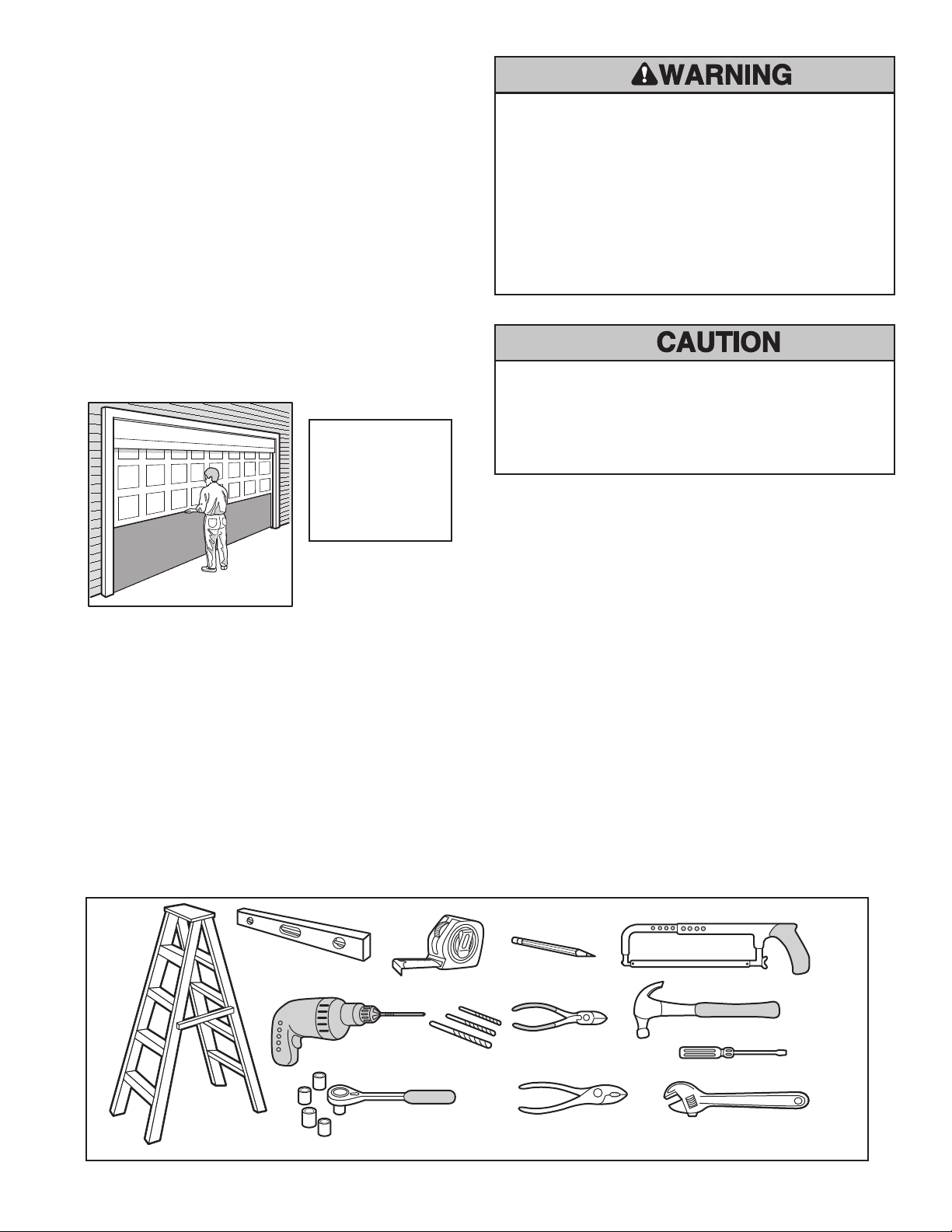
efore you begin:
B
• Disable locks.
• Remove any ropes connected to garage door.
• Complete the following test to make sure your
arage door is balanced and is not sticking or binding:
g
1. Lift the door about halfway as shown. Release the
door. If balanced, it should stay in place, supported
entirely by its springs.
2. Raise and lower the door to see if there is any
binding or sticking (20 Kgf is the absolute maximum
allowable to raise or lower the door in any position).
If your door binds, sticks, or is out of balance, call a
qualified door technician.
Max. door mass
130 kg
(spring balanced).
Max. door curtain
16.5 m
2
To prevent possible SERIOUS INJURY or DEATH:
• ALWAYS call a qualified door technician if garage door binds,
sticks, or is out of balance. An unbalanced garage door may not
reverse when required.
• NEVER try to loosen, move or adjust garage door, door springs,
cables, pulleys, brackets or their hardware, ALL of which are
under EXTREME tension.
• Disable ALL locks and remove ALL ropes connected to garage
door BEFORE installing and operating the garage door opener to
avoid entanglement.
To prevent damage to the garage door and opener:
• ALWAYS disable locks BEFORE installing and operating the
opener.
• ONLY operate the garage door opener at 230 - 240 V, 50 Hz or
battery power to avoid malfunction and damage.
Sectional Door
Tools needed
During assembly, installation and adjustment of the opener, instructions will call for hand tools as illustrated
below.
2
Page 5
Safety
Reversing Sensor
S
upport bracket &
fastening hardware
i
s required.
R
efer page 12.
— — — — — — — —
Header Wall
F
INISHED CEILING
T
orsion
Spring
Safety
Reversing Sensor
Gap between floor and bottom
of door must not exceed 6 mm
Access
Door
Wallmounted
Door
Control
Opener
V
ertical
Centreline
of Door
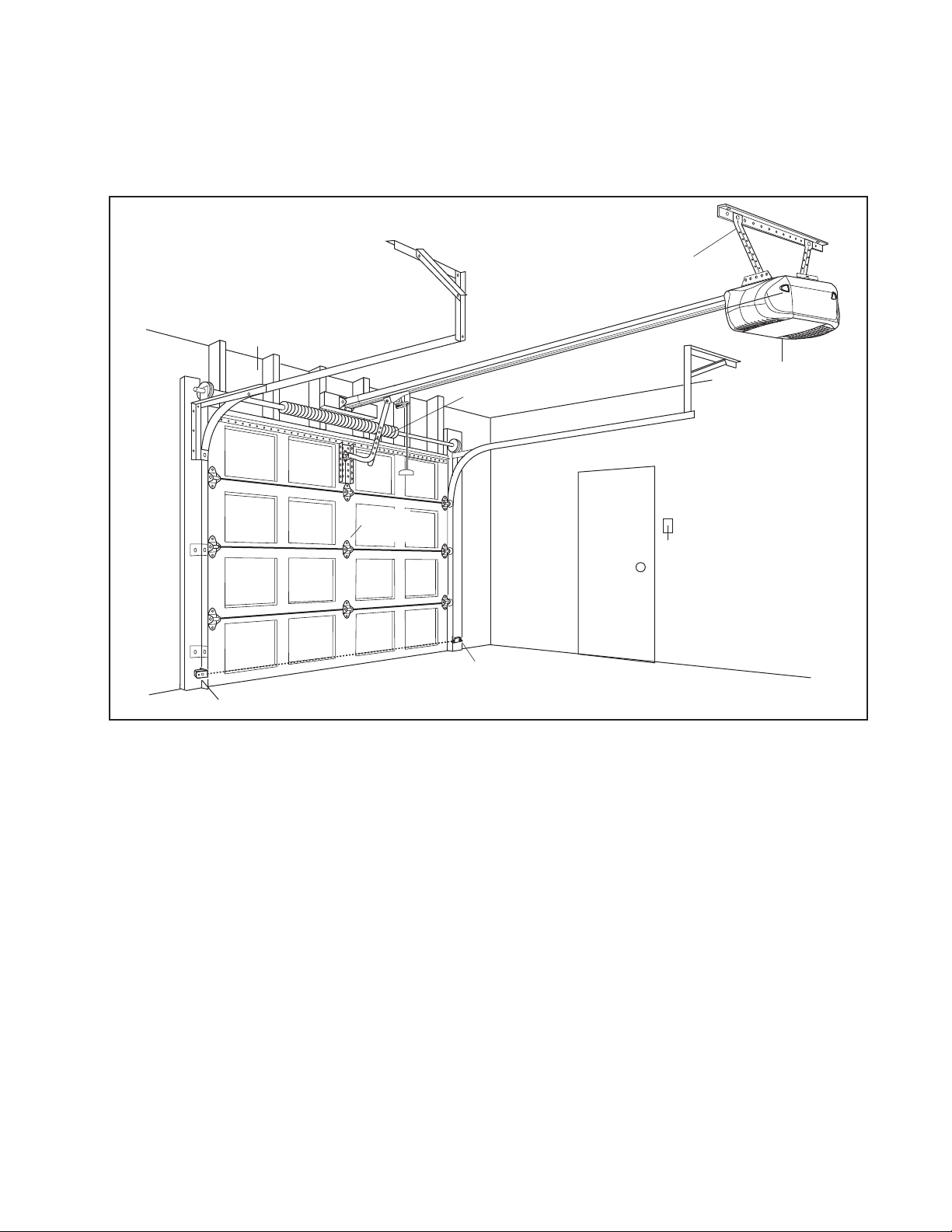
Planning
dentify the type and height of your garage door. Survey your garage area to see if any of the conditions below apply to
I
your installation. Additional materials may be required. You may find it helpful to refer back to this page and the
accompanying illustration as you proceed with the installation of your opener.
SECTIONAL DOOR INSTALLATION
3
Page 6
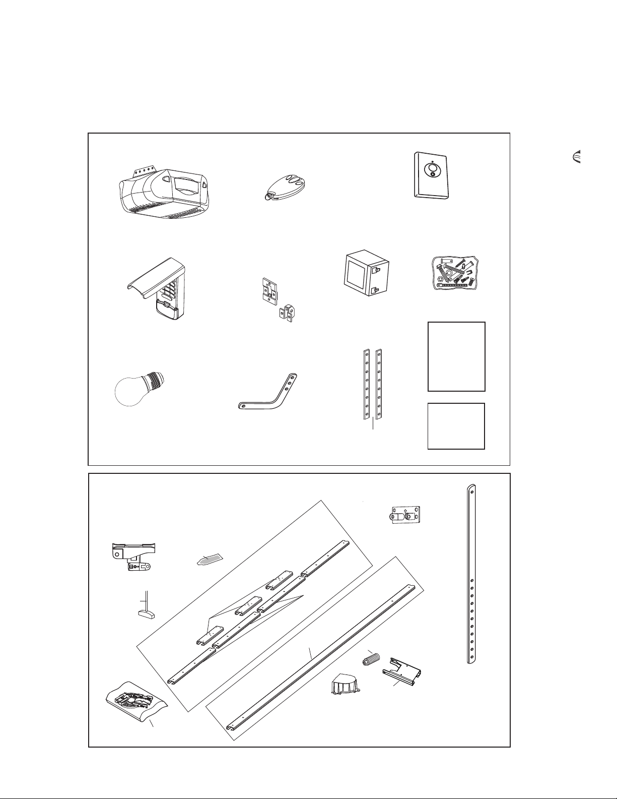
Carton Inventory
Straight Door
Arm Section
Curved Door
Arm Section
Safety Labels
and
Literature
Header Bracket
Belt Pulley Cover
Door Brackets
MT3850EVO Opener
with Twin Light Lenses
Internal Battery
Trolley
N
O
T
I
C
E
Rope &
Handle
Hanging Bracket
Grease
Sectional Rails
Spring
Merlin
E945M 3-Button
Mini-Remote Control
Hardware Bag
E840M Wireless Keypad
x 2
+
Merlin
E128M 2-Button Wireless
Wall Control
+
Opener Carton
Belt Pack &
Inner Trolley
Rail Braces
One Piece Rail
Header Sleeve
Assembly
Rail Cartons
Max. 40Watt
E27 Light Bulb x2
Instruction
Manual
Your garage door opener and rail are packed in two separate cartons. The Whisper Drive MT3850EVO Opener Carton
contains the opener, it’s fitting hardware and accessories. The Rail Carton contains the rail and it’s hardware as illustrated
below. If anything is missing, carefully check the packing material. Parts may be stuck in the foam.
4
Page 7
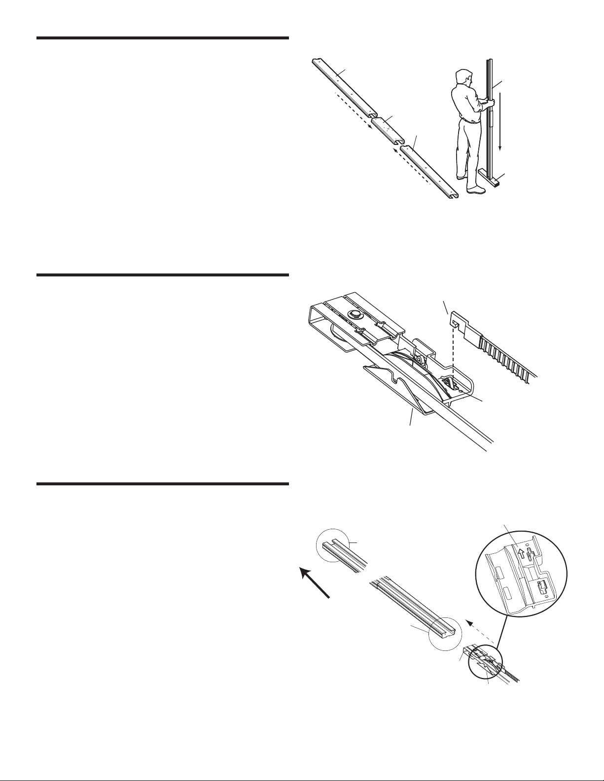
ASSEMBLY STEP 1
Direction Arrow
Header End
Rail Assembly
Pulley Bracket
Inner Trolley
DOOR
Rail Assembly
Wood
Rail Section
Brace
Rail Section
Connector Slot
Trolley Connector
Inner Trolley Assembly
Assemble the Sectional Rail (if used)
If using 1-Piece Rail Proceed to Step 5
o avoid installation difficulties, do not run the
T
garage door opener until instructed to do so.
• Place rail pieces on flat surface for assembly (all four
ections are interchangeable).
s
• Slide rail brace onto rail section.
• Connect rail by sliding rail brace onto next rail section.
• Tap rail assembly on piece of wood until rail sections
are flush (repeat with remaining rail sections until rail
assembly is complete).
ASSEMBLY STEP 2
Install the Belt
• Remove belt from carton and lay it out on the floor, (be
careful not to allow the belt to twist).
• Hook the trolley connector into the connector slot on
the inner trolley assembly.
ASSEMBLY STEP 3
Insert the Belt into the Rail
• Slide pulley bracket and inner trolley into back (opener
end) of rail assembly, ensuring the pulley bracket is
inserted as shown with arrow pointing toward front
(header end) of the rail assembly.
• Push Pulley Bracket through to the Header End of the
rail.
5
Page 8
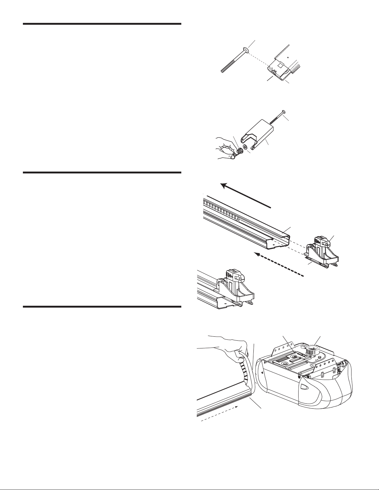
ASSEMBLY STEP 4
Flat Washer
Spring
Header Sleeve
Assembly
Carriage Bolt
Carriage Bolt
Header End
Pulley Bracket
Slot
Trolley
Release Arm
Rail Assembly
D
O
O
R
Sh
i
m Brac
k
e
t
Bel
t
Pul
l
ey
Rail Assembly
Belt
Assemble the Header Sleeve
• Insert carriage bolt head into the Pulley Bracket slot
and retain by pushing the pulley bracket back into the
rail.
• Install the carriage bolt thread through the header
leeve assembly.
s
• Install the flat washer and spring assembly onto the
carriage bolt, do not completely tighten onto thread.
• Slide header sleeve assembly onto front (header end)
of rail.
ASSEMBLY STEP 5
Attach the Trolley to the Rail
Assembly
• Slide outer trolley into the back (opener end) of the
rail assembly. Be sure the end with the trolley release
arm is heading in direction of opener. Slide outer
trolley down rail until it engages with inner trolley.
• Move the engaged trolley assembly to the midpoint of
the rail, then turn the rail assembly or one-piece rail
over ready to fasten to opener.
ASSEMBLY STEP 6
Attach the Rail to the Opener
• Holding belt out of the way.
• Slide the rail assembly onto shim bracket until rail
assembly is securely fastened to the opener.
• Wrap the belt around the belt pulley ensuring the belt
engages the teeth of the belt pulley.
6
Page 9
S
c
r
e
wd
r
i
v
e
r
Nu
t Ri
n
g
S
p
a
n
n
e
r
S
p
r
i
n
g
Nu
t
He
a
d
e
r
S
l
e
e
v
e
Nut Ring Trolley
Nut Ring
Trolley
25 mm 32 mm
BEFORE AFTER RELEASE
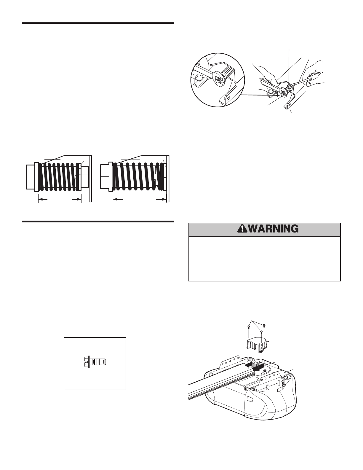
ASSEMBLY STEP 7
Hex Screws
Belt Pulley Cover
Mounting Plate
Opener Belt Pulley
Hex Screw
Set Belt Tension
• Thread spring nut onto the carriage bolt until finger
tight. Insert a screwdriver tip into one of the slots of the
nut ring and brace it firmly against the header sleeve.
• Place a spanner on the square end of the spring nut,
slightly rotate nut about 1/4 turn clockwise until nut ring
is released against header sleeve.
This sets spring for optimum belt tension. Belt may slip off
pulley if belt is too loose. If belt does slip, re-tighten spring
nut by turning nut clockwise a half turn.
Do NOT over-tighten belt.
ASSEMBLY STEP 8
Attach the Belt Pulley Cover
• Grease the Belt and Pulley liberally with the grease
provided in the hardware bag.
• Position the belt pulley cover over the opener belt
pulley so the three holes in the cover align with the
three holes in the mounting plate. Attach with hex
screws provided.
HARDWARE
To avoid possible SERIOUS INJURY to fingers from moving
garage door opener:
• ALWAYS keep hands clear of belt pulley while operating opener.
• Securely attach belt pulley cover BEFORE operating.
7
Page 10
H
eader Wall
Vertical Centreline
o
f Garage Door
L
evel
(optional)
Timber Brace
T
imber brace
S
tructural
S
upports
O
PTIONAL
CEILING
M
OUNT
FOR
HEADER
B
RACKET
Unfinished
C
eiling
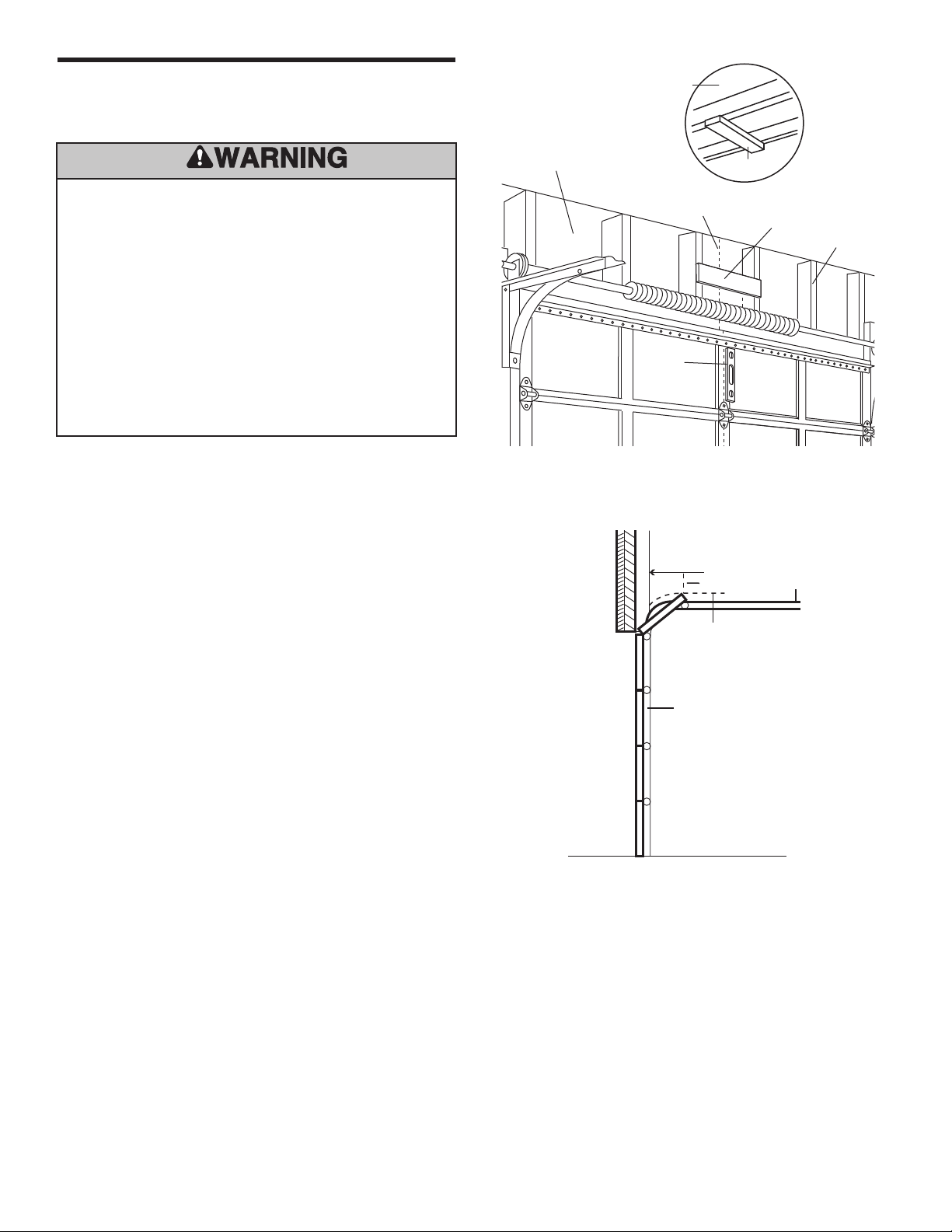
INSTALLATION STEP 1
Header Wall
Sectional door with curved track
Highest Point
of Travel
Door
50 mm
Track
Determine the Header Bracket
Location
To prevent possible SERIOUS INJURY or DEATH:
• Header bracket MUST be RIGIDLY fastened to structural
support on header wall or ceiling, otherwise garage door might
not reverse when required. DO NOT install header bracket over
plasterboard wall.
• Concrete anchors MUST be used if mounting header bracket to
masonry.
• NEVER try to loosen, move or adjust garage door, springs,
cables, pulleys, brackets, or their hardware, ALL of which are
under EXTREME tension.
• ALWAYS call a qualified door technician if garage door binds,
sticks, or is out of balance. An unbalanced garage door might
not reverse when required.
1. Close the door and mark the inside vertical centreline
of the garage door.
2. Extend the line onto the header wall above the door.
3. Open your door to the highest point of travel as shown.
Draw an intersecting horizontal line on the header wall
above the high point 50 mm to 75 mm above the high
point.
This height will provide travel clearance for the top
edge of the door.
NOTE: If the available height above the highest
point of your door is less than recommended, use
the maximum height possible (as long as the door
does not contact the rail), or refer to page 9 for
ceiling installation.
8
Page 11

INSTALLATION STEP 2
C
oach Bolt
50 mm
to 75 mm
Ceiling Mount
Wall Mount
150 mm
(6")
Centre Line
Coach Bolt
Header Bracket
Header Bracket
Centre Line
Coach Bolt
Horizontal Line
Install the Header Bracket
OTE: Refer to vertical centre and horizontal lines
N
created in Step 1 for proper placement of header
bracket.
Wall mount: Centre the header bracket on the vertical
centre line with the bottom edge of the header bracket on
the horizontal line (with the arrow pointing toward the
ceiling). Mark all of the header bracket holes. Then drill
4.5 mm pilot holes and fasten the header bracket with
coach bolts.
HARDWARE
Ceiling mount: Extend vertical centre line onto the
ceiling. Centre the header bracket on the vertical mark no
more than 150 mm (6") from the wall. Make sure the arrow
is pointing toward the opener. Mark all of the header
bracket holes, then drill 4.5 mm pilot holes and fasten the
header bracket with coach bolts. For concrete ceiling
mount, use concrete anchors provided.
9
Page 12

Header
Bracket
Belt Pulley
Bracket
Foam
Packaging
Header Wall
Garage
Door
Ring
Fastener
Header
Bracket
Rail
Ring
Fastener
Clevis Pin
Clevis Pin
Trolley
INSTALLATION STEP 3
S
mall Clevis Pin X 2
Ring Fastener X 2
Long Clevis Pin x 1 (95mm)
Attach the Rail to the Header Bracket
• Position the opener on the garage floor below the
header bracket. Use foam packing material as a
protective base.
OTE: If the door spring is in the way you’ll need
N
help. Have someone hold the opener securely
on a temporary support to allow the rail to clear
the spring.
• Position the rail bracket against the header bracket.
• Align the bracket holes and join with either the single
long clevis pin or the two small clevis pins as shown
Figure 1.
NOTE: Small Clevis Pin should be used if the
carriage bolt is in the way.
• Insert the ring fasteners to secure.
Figure 1
10
HARDWARE
Page 13

INSTALLATION STEP 4
Rail
Door
50 mm spacer should
be used to determine
the correct mounting
position
Header
Bracket
50 mm (2”)
above the highest
point of travel
A
Position the Opener
You will need a 50 mm piece of timber or similar
spacer to gauge the distance between door and rail.
1. Raise the opener onto the support.
2. Open the door completely and place a 50 mm
spacer between the door and the rail
(as shown).
3. If the top section or panel hits the trolley when
you raise the door, pull down on the trolley arm
to disengage the opener. Leave the trolley in this
position until opener is fastened in place.
NOTE: Timber spacers should be left in place until
completion of Installation Step 5.
To prevent scratching or marking the garage door, rest garage
oor opener rail on piece of wood placed on top section of door.
d
11
Page 14

Hex Bolt
Nut
Lock Washer
Coach Bolt
M
easure
D
istance
C
oach Bolts
S
tructural
Supports
Bracket
(Not Provided)
Coach Bolts
(Not Provided)
Bolt
Lock Washer
Nut
—
F
IN
ISH
E
D
C
EILIN
G —
Hidden
Support
Bolt
Lock Washer
Nut
Bolt
L
ock Washer
Nut
Coach Bolts
(Not Provided) Bolt,
Lock Washer
& Nut
Bolt, Lock Washer &Nut
Grease
Grease
Grease
—
F
IN
ISH
ED
C
EILIN
G
—
Bracket
(Not Provided)
INSTALLATION STEP 5
Hang the Opener
Three representative installations are shown. Yours may
be different. Hanging brackets should be angled
(Figure 1) to provide rigid support. On finished ceilings
Figure 2 and Figure 3), attach a sturdy metal bracket to
(
structural supports before installing the opener. This
bracket and fastening hardware are not provided.
1. Remove foam packaging. Measure the distance from
each side of the opener to the structural support.
2. Cut both pieces of the hanging bracket to required
lengths.
3. Drill 4.5 mm pilot holes in the structural supports.
4. Attach one end of each bracket to a support with
8 mm coach bolts.
5. Fasten the opener to the hanging brackets with
8 mm hex bolts, spring washers and nuts.
6. Check to make sure the rail is centred over the door
(or in line with the header bracket if the bracket is not
centred above the door).
7. Remove timber spacer. Operate the door manually. If
the door hits the rail, raise the header bracket.
8. Grease the inside of the rail surface where the trolley
slides with rail grease (provided).
To avoid possible SERIOUS INJURY from a falling garage door
pener, fasten it SECURELY to structural supports of the garage.
o
Concrete anchors MUST be used if installing ANY brackets into
masonry.
Figure 1
Figure 2
NOTE: DO NOT connect power to opener at this
time.
HARDWARE
Figure 3
12
Page 15

INSTALLATION STEP 6
Vertical
C
entreline
of Garage
Door
D
oor
Bracket
Location
H
eader
Bracket
Door
Bracket
Vertical
Centreline
of Garage Door
UP
Vertical
Reinforcement
Door
Bracket
Nut
Bolt
Spring Washer
Vertical
Reinforcement
Self-Threading
Screw
(Not Provided)
Vertical
Centreline
of Garage Door
Bracket Plate
Self-Threading Screw
UP
UP
Inside Edge
of Door or
Reinforcement Board
Bolt
Self-Threading
Screw
(Not Provided)
Vertical
Centreline
of Garage Door
Vertical
Centreline
of Garage
Door
Nut
Spring Washer
Fasten the Door Bracket
. Centre the door bracket on the previously marked
1
vertical centreline used for the header bracket
installation.
OTE: Door bracket must be installed with open end
N
up as illustrated below. If the bracket plate is used
observe the “TOP” indicator on the plate.
2. Position the top edge of the bracket 150-250 mm
below the top edge of the door, OR directly below any
structural support across the top of the door.
3. Mark, drill holes and install as follows, depending on
your doors construction:
Metal or lightweight doors using a vertical angle iron
brace between the door panel support and the door
bracket:
• Drill 4.5 mm fastening holes. Secure the door bracket
using the two self-threading screws (Figure 2A).
• Alternately, use two 8 mm bolts, spring washers and
nuts (not provided) (Figure 2B).
Fiberglass, aluminum or lightweight steel garage doors WILL
REQUIRE reinforcement (not provided) BEFORE installation of
oor bracket. Contact your door manufacturer for reinforcement
d
kit.
Figure 1
Metal, insulated or lightweight factory reinforced
doors:
• Drill 4.5 mm fastening holes. Secure the door bracket
using the self-threading screws (Figure 3).
Wood Doors:
• Use top and bottom or side to side door bracket holes.
Drill 8 mm holes through the door and secure bracket
with 8 mm carriage bolts, spring washers and nuts (not
provided) (Figure 4).
NOTE: The self-threading screws are not intended for
use on wood doors.
HARDWARE
Figure 2B
Figure 2A
Figure 3
Figure 4
13
Page 16

Spring Washer
Nut
Ring Fastener
Hex Bolt
Clevis Pin X 2
HARDWARE
INSTALLATION STEP 7
R
ing
Fastener
Door
B
racket
Clevis Pin
Curved
D
oor Arm
Straight
D
oor Arm
Clevis Pin
Outer Trolley
L
ock
Washers
Nuts
Door Bracket
Bolts
Emergency
Release
Handle
Lock
Washers
Nuts
Bolts
Cut This End
2
0
0
m
m
Connect Door Arm to Trolley
ake sure garage door is fully closed. Pull the
M
emergency release handle to disconnect the outer trolley
from the inner trolley. Slide the outer trolley back (away
from the door) about 200 mm (Figures 1, 2 and 3).
Figure 1:
• Fasten straight door arm section to outer trolley with
the clevis pin. Secure the connection with a ring
fastener.
• Fasten curved section to the door bracket in the
same way, using the clevis pin.
Figure 2:
• Bring arm sections together. Find two pairs of holes
that line up and join sections. Select holes as far
apart as possible to increase door arm rigidity.
Figure 3:
• If holes in curved arm are above holes in straight
arm, disconnect straight arm. Cut about 150 mm
from the solid end. Re-connect to trolley with cut end
down as shown.
• Bring arm sections together.
• Find two pairs of holes that line up and join with
bolts, spring washers and nuts.
Pull the emergency release handle toward the opener at
a 45° angle so that the trolley release arm is horizontal.
Figure 1
Figure 2
Figure 3
14
Page 17

Lens Hinge
40 Watt (Max)
Standard Light Bulb
Release Tab
INSTALLATION STEP 8
Overhand
Knot
Overhand
Knot
Emergency
Release Handle
Rope
Trolley Release Arm
Install the Lights
• Press the release tabs on each side of lens. Gently
rotate lens back and downward until the lens hinge is
in the fully open position. Do not remove the lens.
• Install a 40 watt maximum light bulb in each socket.
Light bulb size should be E27, standard ‘GLS’ base
only. The lights will turn ON and remain lit for
approximately 2-1/2 minutes when power is connected.
Then the lights will turn OFF.
• Reverse the procedure to close the lens.
NOTE: Lights do not turn on in battery mode.
• Use E27 standard 40 watt bulbs for replacement as
shown.
To prevent possible OVERHEATING of the endpanel or light
socket:
• DO NOT use short neck or specialty light bulbs.
o prevent damage to the opener:
T
• DO NOT use bulbs larger than 40 W.
• ONLY use E27 size bulbs.
• DO NOT USE CFL (Compact Fluorescent Lamps) or Reflective
Lamps as they may cause damage to the lens cover. If unsure call
the Chamberlain customer service.
INSTALLATION STEP 9 Attach the
Emergency Release Rope and Handle
• Thread one end of the rope through the hole in the top
of the red handle so “NOTICE” reads right side up as
shown. Secure with an overhand knot at least
25 mm from the end of the rope to prevent slipping.
• Thread the other end of the rope through the hole in
the release arm of the outer trolley.
• Adjust rope length so the handle is no more than 1.8m
above the floor. Ensure that the rope and handle clear
the tops of all vehicles to avoid entanglement. Secure
with an overhand knot.
NOTE: If it is necessary to cut the rope, heat seal the
cut end to prevent unraveling.
• To release the trolley, pull down on the red handle. Do
not use the handle to open or close the door.
To prevent possible SERIOUS INJURY or DEATH from a falling
garage door:
• If possible, use emergency release handle to disengage trolley
ONLY when garage door is CLOSED. Weak or broken springs or
unbalanced door could result in an open door falling rapidly
and/or unexpectedly.
• NEVER use emergency release handle unless garage doorway
is clear of persons and obstructions.
• NEVER use handle to pull door open or closed.
15
Page 18

INSTALLATION STEP 10
Battery
Battery Cover
B
attery
Status LED
Install the Battery Backup
• Make sure the opener is unplugged.
Open the lens cover at the power cord end.
•
• Using a Phillips-head screwdriver, remove the battery
cover on the opener.
• Partially insert battery into the opener with the
terminals facing out.
• Connect red (+) and black (-) wires from the opener to
corresponding terminals on battery.
• Replace battery and lens covers.
• CONNECT THE OPENER TO MAINS POWER.
NOTE: Opener will operate without battery installed,
when mains power is connected.
NOTE: LED is most visible with opener light off.
GREEN LED: All systems are normal.
• A solid LED light indicates the battery is fully charged.
• A flashing LED indicates the battery is being charged.
NOTE: Battery does not have to be fully charged to
operate the opener.
To reduce the risk of FIRE or INJURY to persons:
• Do NOT wear rings, watches or metal bracelets whilst handling
the battery.
• Disconnect ALL electric and battery power BEFORE
performing ANY service or maintenance.
• Use only Chamberlain part # 041A6357-2 for replacement
battery.
• Do NOT dispose of battery by burning. Battery may explode.
Check with local authority for disposal instructions.
Battery Backup
OPERATING INSTRUCTIONS
1. Test the installed battery with the opener after the
limits and force have been set.
To test the battery, disconnect the opener power cord
from the electrical outlet.
• A solid orange LED indicates the opener is operating
on battery power.
• A flashing orange LED with beep indicates the opener
is operating on battery power and that the battery
charge is low.
• To test the battery is functioning properly, open and
close the garage door.
• Re-connect the opener power cord into the electrical
outlet.
• Verify that the green LED is flashing on the Battery
status LED (indicates that the battery is now charging).
• Test completed.
ORANGE LED:
The opener has lost mains power and is operating on
battery power.
• A solid LED with beep, sounding approximately every
2 seconds, indicates the opener is activating the door
and is operating off the battery.
• A flashing LED with beep, sounding every 30 seconds,
indicates battery is low.
• Once the power is restored the battery will recharge.
This is indicated by a flashing green LED.
RED LED:
• If a red LED remains on when the power is restored,
and is accompanied by a beep sounding every 30
seconds, replace the battery and allow 48hrs for it to
fully charge. If the RED LED remains on after this time
contact a qualified door technician.
Charging the battery.
• Battery will take 24 to 48 hours to fully charge.
A fully charged battery supplies 12 V DC to the opener
for one to two days of normal operation during an
electrical power outage. If the battery voltage drops too
low, the battery will disconnect and the opener will no
longer operate under battery power.
After the electrical power has been restored, the battery
will recharge within 48 hours. Under normal usage
batteries will last 3 to 5 years.
To obtain maximum battery life and prevent damage,
disconnect the battery when opener is unplugged for
an extended period of time.
NOTE: Door operation may be limited until battery is
fully charged. The opener’s lights will not turn on
during battery mode.
16
Page 19

Indicator Light
ADJUSTMENT STEP 1
Indicator Light
B
E
E
P
UP Arrow
Button
L
earn Limits
Button
DOWN Arrow
B
utton
Battery
Status
LED
L
earn
Button
LED
Indicator Light
Indicator Light
Program the Travel Limits and Force
Settings
Figure 1
Without a properly installed safety reversal system, persons
(particularly small children) could be SERIOUSLY INJURED or
ILLED by a closing door.
K
• Incorrect adjustment of garage door travel limits will interfere with
proper operation of safety reversal system.
• NEVER use force adjustments to compensate for a binding or
ticking garage door.
s
• After ANY adjustments are made, the safety reversal system
MUST be tested. Door MUST reverse on contact with 40 mm
high object laid flat on floor.
NOTE: Travel limits regulate the points at which the
door will stop when moving up or down. Follow the
steps below to set the limits.
To program the travel limits:
1. Press and hold the Learn Limits Button until a beep
is heard and the UP Arrow Button and indicator light
begin to flash (figure 2).
2. Press and hold the UP Arrow Button until the door is in
the desired UP position (figure 3).
NOTE: The UP and DOWN Arrow Buttons can be
used to move the door up and down as needed.
3. Once the door is in the desired UP position press and
release the Learn Limits Button. The DOWN Arrow
Button will begin to flash (figure 4).
4. Press and hold the DOWN Arrow Button until the door
is in the desired DOWN position (figure 5).
NOTE: The UP and DOWN Arrow Buttons can be
used to move the door up and down as needed.
5. Once the door is in the desired DOWN position press
and release the Learn Limits Button. The UP Arrow
Button will begin to flash (figure 2).
6. Press and release the UP Arrow Button to test the UP
limit. When the door travels to the programmed UP
limit, the DOWN Arrow Button will begin to flash.
7. Press and release the DOWN Arrow Button to test the
DOWN limit. The door will travel to the programmed
DOWN limit.
The Travel Limits and Force Setting has now been set.
To prevent damage to vehicles, be sure fully open door provides
adequate clearance.
Figure 2
Figure 3
Figure 4
TIPS : Repeated operation of the garage door opener
during adjustments may cause the motor to
overheat. Wait 15 minutes and try again.
If anything interferes with the door’s upward travel
it will stop. If anything interferes with the door’s
downward travel, it will reverse.
Figure 5
17
Page 20

ADJUSTMENT STEP 2
1
40 mm
+
Test the Safety Reversal System
EST
T
• With the door fully open, place a 40 mm high object laid
flat on the floor, centred under the garage door.
• Operate the door in the down direction. The door must
reverse on striking the obstacle.
ADJUST
• If the door stops on the obstacle, it is not travelling far
enough in the down direction. Complete Adjustment
Step 1, Programming the Limits and Forces to increase
travel distance in the down direction.
NOTE: Make sure the limit adjustments do not
force the door arm beyond a vertical position.
Refer Figure 3, page 14.
• Repeat the test.
• When the door reverses on the 40 mm high object laid
flat, remove the obstacle and run the opener through 3
or 4 complete travel cycles to test adjustment.
• If the opener continues to fail the Safety Reverse Test,
call for a qualified door technician.
Safety reversal system MUST be tested every month.
•
• After ANY adjustments are made, the safety reversal system
MUST be tested. Door MUST reverse on contact with 40 mm
bstacle on the floor.
o
IMPORTANT SAFETY CHECK:
Test the Safety Reverse System once a month and after:
• Each adjustment of door arm length, limits, or force
controls.
• Any repair to or adjustment of the garage door
(including springs and hardware).
• Any repair or changes to the garage floor.
• Any repair or adjustment of the opener.
INSTALLING YOUR WIRELESS E128M WIRELESS WALL BUTTON
Disconnect power to the opener whilst installing
accessory to prevent accidental activation.
Locate minimum 1.5 m above the floor
To install:
• Carefully pry open the E128M and locate the two screws for
mounting.
• Attach to the wall using the two screws and wall anchors provided
if mounting to a plaster wall. If using a recessed wall box do not
use anchors.
this
NOTE: Do not overtighten screws.
NOTE: The wall control supplied with your opener should be pre-programmed by the factory.
If adding a new wall control, program into the opener before mounting the unit as detailed in the next section.
18
Page 21

INSTALL THE PROTECTOR
M
ount Bracket
With Square Holes
Screws
“C” Wrap
Lock Nuts
Mounting Bracket
w
ith slot
L
ock Nuts
Lag Screws
Carriage Bolts
(with Square Shoulders)
Garage
Wall
“
C” Wrap
M
ounting Bracket
with Square Holes
Garage
wall
“C” Shaped
Wrap
Mounting Brackets
with Square Holes
Carriage Bolts
Lock Nuts
Drill
9.5 mm
Holes
Garage
Track
Installing The Protector System to Track
ALL INSTALLATIONS
Installing The Protector System to the Garage Wall
T
M
TM
“C” Wrap
Garage
Wall
Mounting Bracket
with Square Holes
Garage-
Floor
Mounting
Bracket
with Holes
Alternate Wall Mount
Sensor
Garage
Wall
Alternate Floor Mount
Mounting Bracket
with Slot
Mounting Bracket
with Square Holes
Holder
Sensor
Garage
Floor
Indicator Light
Indicator
Lamp
Attach with
concrete anchors
(not provided)
white
grey
To release wires
press tab with a
screwdriver or
pen
6mm
TM
SYSTEM
NOTE: This accessory must be used for all
installations where the closing force as measured on
the bottom of the door is over 400 N (40 kgf).
(OPTIONAL)
To protect small children, install The Protector
ystem™ no higher than 100 mm above the floor.
S
Disconnect power to the garage door opener before
installing The Protector System™.
Figures 1, 2 and 3 show recommended assembly of
bracket(s) and "C" wrap based on the wall installation of
the sensors on each side of the door shown above, or on
the door tracks themselves. Figure 4 shows variations
which may fit your installation requirements better. Make
sure the wraps and brackets are aligned so the
sensors will face each other across the door.
• Connect each assembly to a slotted bracket, using the
hardware shown. Note alignment of brackets for left
and right sides of the door. Finger tighten the lock
nuts.
• Use bracket mounting holes as a template to locate and
drill two (4.8 mm) diameter pilot holes on both sides of
the door so that the beam mounting height is no greater
than 100 mm above the floor.
• Attach bracket assemblies with carriage bolts as shown.
• Adjust right and left side bracket assemblies to the same
distance out from mounting surface. Make sure all door
hardware obstructions are cleared. Tighten the lock
nuts.
• Centre each sensor unit in a "C" wrap with lenses
pointing toward each other across the door.
• Secure sensors with the hardware provided. Finger
tighten the wing nut on the receiving eye to allow for final
adjustment. Securely tighten the sending eye wing nut.
• Run wires from both sensors to the opener and connect
the two white only wires to the white terminal and the
black/white wires to the grey terminal on your opener
(refer figure 5).
igure 1
F
Figure 2
Figure 3
Figure 5
Figure 4
19
Page 22

ENABLING THE PROTECTOR SYSTEM:
UP Arrow
Button
Learn Limits
Button
DOWN Arrow
Button
Battery
Status
LED
Learn
Button
LED
Figure 1
• The Protector System is automatically enabled once the beams are connected to the opener and the
power is turned on for 2 minute initialising period.
• During this 2 minute initialising period there should be no obstruction placed between the beams, and
o door activations. If an activation or obstruction does occur, the door will not reverse and the 2 minute period
n
will need to be recommenced.
ISABLING THE PROTECTOR SYSTEM:
D
If the protector System is not required, it will be necessary to deactivate the opener so that normal operations
can occur.
NOTE: This process also Erases all the Transmitter codes from the memory.
• Disconnect power, Remove the Protector System wiring from the opener, reconnect power.
• Press and hold the “learn” button until the learn indicator goes out, approx 6 seconds.
• Relearn the transmitter codes you wish to install, see page 21 WIRELESS PROGRAMMING
• The opener can now operate without the Protector System installed.
TIMER-TO-CLOSE FEATURE (TTC)
Door may operate unexpectedly, therefore do not
allow anything to stay in the path of the door.
NOTE: Requires The Protector SystemTM(IR Beams) installed and initialised for 2 minutes
The Timer-to-close feature allows the door to automatically close after a specified time period that can be adjusted using the door
control buttons (figure 1). Prior to the door closing, the ‘Alert-2-close’ feature activates audible (garage door opener beeps) and visual
alerts (garage door opener lights flash) for 8 seconds before the door begins to close.
If the door encounters an obstruction while closing, the opener will make a second attempt to close the door. If an obstruction occurs
on the second attempt, the garage door opener will open, stop and WILL NOT close until the obstruction has been cleared, and the
opener has been operated again.
Enabling TTC using the buttons in Opener
Door must be in the closed position to commence the setup procedure.
With the door closed press and hold DOWN arrow button for 3 seconds to enter setup mode, when activated LED indicator will flash.
Press the Yellow learn button to toggle the 4 available modes shown below. The small LED indicator will flash the number of times
according to time delay set. Press Black rectangle button (learn limits button) to set and exit.
OFF = 1 long flash
1 min = 1 short flash
5 min = 2 short flashes
10 min = 3 short flashes
20
Page 23

WIRELESS PROGRAMMING
1
3
2
Black Limit
Set Button
UP Arrow
Button
I
ndicator
Light
Programming using the Learn Button
Learn
B
utton
OR
E943M
E945M
UP Arrow
B
utton
Learn Limits
Button
D
OWN Arrow
Button
Battery
S
tatus
L
ED
Learn
Button
L
ED
To Add or Reprogram a Hand-held Remote Control
Activate the opener only when door is in full view, free of
bstruction and properly adjusted. No one should enter or leave
o
garage while door is in motion. Do not allow children to operate
push button(s) or remote(s). Do not allow children to play near the
door.
NOTE: The remote controls supplied with your opener
are pre-programmed to your opener in the factory. If
you purchase additional remote controls, you will
need to program them into your opener using the
steps below.
NOTE: If adding an installed wall control (E128M) you
will need a second person to press and hold the
desired button. If not installed, program the wall
button into the opener before mounting.
Using the Learn Button:
1. Press and hold the button (Fig 1) that you wish to
operate your garage door. The Orange indicator light
on the opener will flash continuously.
2. Press and release the “learn” button on the opener.
3. The opener lights flash when it has learned the code.
If light bulbs are not installed, one click will be heard.
4. Ensure there are no obstructions in the path of the
door, then press the remote control button to test the
door.
To Erase All Codes From Opener
Memory
To deactivate any unwanted remote, first erase all codes:
Press and hold the “learn” button on the opener until the
learn indicator light goes out (approximately 6 seconds).
All previous codes are now erased. Reprogram each
remote or keyless entry device you wish to use.
3-Button Remotes
If provided with your garage door opener, the large button
is factory programmed to operate it. Additional buttons on
any 3-button remote or mini-remote can be programmed
to operate other Merlin Professional garage door openers
or gate openers.
Figure 1
21
Page 24

WIRELESS PROGRAMMING
2
3
3
Press and
release
the yellow
learn button
Enter a 4-digit
PIN of your
choice
? ? ? ?
_ _ _ _
Press and release
the enter button
Light bulb blinks
4
1
Locate
t
he yellow
learn button
KEYLESS DEVICE PROGRAMMING
ctivate the opener only when door is in full view, free of
A
obstruction and properly adjusted. No one should enter or leave
garage while door is in motion. Do not allow children to operate
push button(s) or remote(s). Do not allow children to play near the
door.
Wireless Keypad E840M
To set the keyless entry PIN:
1.Locate the Yellow Learn button on the garage door
opener.
2.Press and release the Yellow Learn button on the
garage door opener.
3.Enter a 4-digit personal identification number (PIN) of
your choice.
4.Press and release the ENTER button. Check to see if
the bulb blinks. If not, slowly press and release the
ENTER button until the light bulb blinks.
To change an existing keyless entry PIN:
1.Enter the existing programmed PIN that you want to
change.
2.Press and hold the # button until the light bulb blinks
twice.
3.Enter the new 4-digit PIN of your choice, then press
the ENTER button. The light bulb will blink once.
4.To test, enter the new PIN, then press the ENTER
button. The garage door opener will activate.
22
Page 25

ROUBLE SHOOTING
T
1. Opener doesn't operate from either door control or
emote:
r
• Does the opener have electric or battery power? Plug
lamp into outlet. If it doesn't light, check the fuse box or
the circuit breaker. (Some outlets are controlled by a
wall switch.)
Have you disengaged all door locks? Review installation
•
instruction warnings on page 1.
• Is there a build-up of ice or snow under door? The door
may be frozen to ground. Remove any obstruction.
• The garage door spring may be broken. Have it
replaced.
• Check battery LED for status, refer page 17.
2. Door operates from door control but not from
remote:
• Replace batteries in the remote if necessary.
• If you have two or more remotes and only one operates,
review Program Your Opener, Remote and Keyless
Entry pages 21 and 22.
• Is the Locked mode displayed on the LCD? The opener
is in lock mode. Push and hold the Lock button for 2
seconds.
3. Remote has short range:
• Check the battery in the remote is fully charged.
• Change the location of the remote control on the car.
• A metal garage door, foil-backed insulation or metal
siding will reduce the transmission range.
4. Door reverses for no apparent reason and opener
light flashes 10 times after reversing:
Check The Protector System™ (if you have installed this
accessory). If the light is flashing, correct alignment.
5. The garage door opens and closes by itself:
Make sure remote push button is not stuck "on".
6. Door stops but doesn't close completely:
Repeat Setting the Limits, refer page 18.
Repeat safety reverse test after any adjustment of door
arm length, close force or down limit.
7. Door opens but won't close:
• Check The Protector System™ (if you have installed this
accessory). If the light on the Beams are flashing,
correct the alignment.
• If opener light does not flash and it is a new installation,
repeat Setting the Limit and Force page 18.
Repeat the safety reverse test after the adjustment is
complete.
8. Opener lights do not turn on:
Unit may be operating on battery power.
• Check battery status LED, refer page 17.
• Replace light bulb (230 V/40 W maximum).
. Opener strains:
9
Door may be unbalanced or springs are broken. Close
door and use manual release rope and handle to
disconnect trolley. Open and close door manually. A
properly balanced door will stay in any point of travel
hile being supported entirely by its springs. If it does
w
not, call for professional garage door service to correct
the problem.
10. Opener hums briefly, then won't work:
• Garage door springs are broken. SEE ABOVE.
• If problem occurs on first operation of opener, door is
locked. Disable door lock.
Repeat safety reverse test after adjustment is complete.
11. Opener won't activate due to power failure:
• Check battery backup system on page 17.
• Pull manual release rope and handle down to
disconnect trolley. Door can be opened and closed
manually. When the power is restored, pull the manual
release handle down and toward opener. The next time
the opener is activated, the trolley will re-connect.
• The Outside Quick Release accessory (if fitted)
disconnects the trolley from outside the garage in case
of power failure.
23
Page 26

DIAGNOSTIC UP DOWN SYMPTOM POSSIBLE CAUSE POSSIBLE RESOLUTON
CODE ARROW ARROW
1-1 1 FLASH 1 FLASH
The garage door opener will The Protector System is not Check the Protector System is
not close and the lights will
flash
installed, connected, or installed and aligned correctly,
wires may be cut both LEDs are ON with no
obstruction between the beams.
1-2 1 FLASH 2 FLASHES
The garage door opener will The Protector System wire Check the Protector System is
not close and the lights will shorted or reversed installed and aligned correctly,
flash both LEDs are ON with no
obstruction between the beams.
1-3 1 FLASH 3 FLASHES
Wall mounted door control The wires for the door control Check the door control wiring is
will not function are shorted or the door correct
control is faulty
1-4 1 FLASH 4 FLASHES
The garage door opener will Misaligned or obstructed Check the Protector System is
not close the door and the Protector System installed and aligned correctly,
lights flash both LEDs are ON with no
obstruction between the beams.
1-5 1 FLASH 5 FLASHES
The garage door opener clicks Internal fault Contact service centre
but no movement
The opener runs approximately Communication error to Contact service centre
150-200 mm and stops and/or
reverses
travel module
Your garage door opener is programmed for self-diagnostic capabilities. The UP and DOWN arrows on the garage door opener flash the diagnostic codes.
DIAGNOSTIC CHART
TM
TM
TM
TM
TM
TM
24
Page 27

DIAGNOSTIC UP DOWN SYMPTOM POSSIBLE CAUSE POSSIBLE RESOLUTON
CODE ARROW ARROW
3-3 3 FLASHES 3 FLASHES
The garage door opener fails to Battery LED flashing green, Recharge Battery, contact
operate and the battery LED is charging circuit stops and starts service centre
constantly flashing green to drain causing battery charging
status
4-1 4 FLASHES 1 FLASH
Door is closing, stops and Obstruction, binding or sticking
Remove obstruction, service door.
reverses door
4-2 4 FLASHES 2 FLASHES
The door stops while opening Obstruction, binding or sticking
Remove obstruction, service door.
for no apparent reason door
4-3 4 FLASHES 3 FLASHES
The door reverses for no
Obstruction, binding or sticking
Reset limits & force, service door.
apparent reason or after touching
door
the floor
4-4 4 FLASHES 4 FLASHES
The door reverses for no apparent Obstruction, binding or sticking
Reset limits & force, service door.
reason or after touching the floor door
4-5 4 FLASHES 5 FLASHES
The opener runs approximately Communication error to travel
150-200 mm and stops and/or
reverses
module Reset limits & force, contact
service centre
4-6 4 FLASHES
6 FLASHES
The door reverses for no apparent The Protector System was Remove obstruction, or realign
reason while travelling down
temporarily obstructed or
misaligned
the Protector System
My garage door opener light(s) will not turn off when the door is open:
Refer to
Battery Status LED
section.
The garage door opener is equipped with a feature that turns the light on
My remote control will not activate the door:
when the Protector System has been obstructed or when the motion
* Verify the Lock feature is not activated on the door control. sensor on the door control detects movement in the garage. These
* Reprogram the remote control.
features can be disabled using the door control, refer to the
Door Control
* If the remote control will still not activate the door check the diagnostic section.
codes to ensure the garage door opener is working properly.
My neighbour's remote control opens my garage door:
* Ensure the antenna wire is hanging down from the garage door opener. Erase the memory from your garage door opener and reprogram the
remote control(s).
My garage door opener beeps every 30 seconds:
These are additional troubleshooting issues that will not show up in the diagnostic codes:
TM
TM
TM
25
Page 28

or
Carefully
Remove Battery
(CR2032 x 1)
USING YOUR GARAGE DOOR OPENER
Your opener can be activated by any of the following devices:
• Open control panel: Up and Down Buttons.
The Outside Keyswitch or Keyless Entry System (if you
•
have installed either of these accessories).
• The Remote Control Transmitter. Hold the push button
down until the door starts to move.
Opening the Door Manually: Door should be fully closed if
possible. Weak or broken springs could allow an open
door to fall rapidly. Property damage or serious personal
injury could result.
The door can be opened manually by pulling the release
andle down. To reconnect the door, pull the release handle
h
down and toward the opener.
Do not use the manual release handle to pull the door
open or closed. When the Opener is Activated by Remote
Control:
1. If open, the door will close. If closed, the door will open.
2. If closing, the door will stop.
3. If opening, the door will stop (allowing space for entry and
exit of pets and for fresh air).
4. If the door has been stopped in a partially open or closed
position, it will reverse direction.
5. If an obstruction is encountered while closing, the door will
reverse.
6. If an obstruction is encountered while opening, the door will
reverse and stop.
7. The optional Protector System™ uses an invisible beam
which, when broken by an obstruction, causes a closing
door to open and prevents an open door from closing. It is
STRONGLY RECOMMENDED for homeowners with young
children.
The opener lights will turn on under the following conditions:
when the opener is initially plugged in; when power is restored
after interruption; when the opener is activated or when the IR
Beams are triggered with the door in the Open position.
They will turn off automatically after 2-1/2 minutes or provide
constant light when the Light feature on the LCD Motion
Detecting Control is activated. Bulb size is E27. Bulb power is
40 watts maximum.
PECIFICATIONS
S
Input Voltage..... 230-240 VAC, 50 Hz
Max. Pull Force 800 N
Rated Load ....... 8 Nm
Standby Power . <1 W
Max. Door Mass 130 kg (spring balanced)
Max. Door Area 18.0 m
2
Motor
Type.................. DC gearmotor permanent
lubrication
Drive Mechanism
Drive ................. Belt with two-piece trolley on
steel rail.
Length of Travel Adjustable to 3 m
Travel Rate ....... 127-178 mm per second
Lamp................. On when door starts, off 2-1/2
minutes after stop.
Door Linkage .... Adjustable door arm. Pull cord
trolley release.
Safety
Personal ........... Push button stop in UP and
DOWN direction. Automatic
safety reverse and stop in UP
and reverse in DOWN
direction.
Electronic.......... Automatic force adjustment
Electrical ........... Transformer overload protector
and low voltage push button
wiring.
Limit Device ...... Optical RPM/Passpoint
detector.
Limit Adjustment Electronic, Semi and Fully
Automatic.
Start Circuit....... Low voltage push button circuit.
Dimensions
Length (Overall) 3.2 m for standard 2.3 m rail
Headroom Required 30 mm
Hanging Weight 14.5 kg
Receiver
Memory Registers 64
Operating Frequency 433.30/433.92/434.54 MHz
SPECIAL NOTE: Chamberlain strongly recommends
that The Protector SystemTM(IR Beams) be installed
on all garage door openers.
To prevent possible SERIOUS INJURY or DEATH:
• NEVER allow small children near batteries.
• If battery is swallowed, immediately notify doctor.
THE REMOTE CONTROL BATTERY
To replace battery, use a screwdriver
blade to pry open the case as shown.
Insert battery positive side up.
Dispose of old battery properly.
CARE OF YOUR OPENER
MAINTENANCE SCHEDULE
Once a Month
• Manually operate door. If it is unbalanced or binding,
call a qualified door technician.
• Check to be sure door opens & closes fully. Adjust
limits and/or force if necessary, refer page 18.
• Repeat the safety reverse test. Make any necessary
adjustments..
Once a Year
• Lightly grease the belt, belt pulley and inside the rail
assembly where the trolley slides.
• Internally the opener does not require additional
lubrication.
26
Page 29

041A6357-2
Battery
108D0184
Light lens
108D0184
Light lens
041A5633-18
Cover assembly
041C0254
Transformer
041A6863-4
End panel with
battery door & screw
041A6864-2
Receiver logic assembly
041B4375-3
Terminal block
with screws
041A7125
Light socket
041A7124-1
Line cord
041A5845
Belt Pulley cover
and sprocket
041D0794-1
Motor with
positioning sensor
041A6281-2
Wire harness kit
041A7114-7
Positioning sensor
ACCESSORIES
4
3
5
1
2
E840M
E128M
760E
CM1702
C77
E940M E943M
E945M
6
7
8
(1) Model E128M Wireless Wall Button
(2) Model E940M 1 Channel visor remote control
(3) Model E943M 3 Channel visor remote control
(4) Model E945M 3 Channel mini remote control
(5) Model E840M Keyless Entry System
(6) Model C77 The Protector System
(7) Model CM1702 Quick Release Lock
(8) Model 760E Outside Keyswitch
TM
OPENER ASSEMBLY PARTS - Information for Service Personnel
If the supply cord is damaged, it must be replaced by the
manufacturer, its service agent or similarly qualified persons in
order to avoid hazard.
27
Page 30

REPLACEMENT PARTS - Information for Service Personnel
NO
T
I
CE
041A2828
Release rope
a
nd handle
012B0905
Door bracket
178B0034B
Straight arm
012C0778
Rail chassis straps
083A0011
G
rease
0
41A5414-9
H
ardware bag
012B0906
Door bracket plate
041A5800
Outer trolley
1
83D0177
Segmented rail sections
1
83D0178
Segmented rail braces
012C0855
Header bracket
1
71A0028
031D0537
Belt pulley cover
Replacement belt packs
041A5844 (2.3m)
041A5844-1 (2.5m)
041A5844-2 (3.0m)
8423CR3
8430CR3
One Piece Rails
8023CR3 2.3m
8025CR3 2.5m
8030CR3 3m
041B4103
Belt tensioner
0
41A6398
Inner trolley repair kit
1
4
4
C
0
0
7
7
I
d
le
r
p
u
l
le
y
012C0810
E
nd bracket 30mm steel
178B0086B
Curved arm
041B5669
Belt joining Kit
Required for shortening belts
28
Page 31

CHAMBERLAIN LIMITED WARRANTY
erlin Professional Whisper Drive MT3850EVO
M
Sectional Garage Door Opener
Chamberlain Australia Pty Limited / Chamberlain New Zealand Limited
(Chamberlain), the manufacturer of Merlin
openers, is committed to manufacturing and supplying high quality goods.
As part of this commitment, we seek to provide reliable service and
support for our goods and are pleased to provide you, the original
purchaser, with this Chamberlain Limited Warranty.
We also provide the following statement as required by the Australian
Consumer Law: In Australia, in addition to your rights under this
Chamberlain Limited Warranty, our goods come with guarantees that
cannot be excluded under the Australian Consumer Law. You are entitled
to a replacement or refund for a major failure and for compensation for
any other reasonably foreseeable loss or damage. You are also entitled
to have the goods repaired or replaced if the goods fail to be of
acceptable quality and the failure does not amount to a major failure.
Chamberlain’s warranty
Chamberlain warrants to the original purchaser of the Merlin
MT3850EVO Sectional Door Opener (Unit) that all parts of the Unit, other
than remote controlled transmitters and accessories, globes and batteries,
are free from defects in materials and workmanship for a period of 60
months or 15,000 cycles (opening & closing of the garage door)
whichever comes first, from the date of purchase when installed in a
residential premise with a residential specified garage door that is
designed for the sole purpose of domestic domicile. Chamberlain warrants
that remote controlled transmitters and accessories included with the Unit
are free from defects in materials and workmanship for a period of 12
months from the date of purchase.
Batteries and globes are not covered under the Chamberlain Limited
Warranty.
It is a condition of this Chamberlain Limited Warranty that the Unit is sold,
installed and serviced by a Professional Dealer appointed by
Chamberlain. A Merlin
internet and installed by a person other than a Professional Dealer will not
be covered by this Chamberlain Limited Warranty.
It is also a condition of this warranty that the garage door is operable by
hand and opens and closes with no more than a maximum of 20 kgs of
lifting weight. It is also a condition of the Chamberlain Limited Warranty
that the Unit is serviced by a Professional Dealer during the period 24
months to 36 months after the initial installation date. The garage door
service fee will be at the purchaser’s expense.
NB: The Australian Garage Door Association directs attention to
consumers to maintain your garage door in good running order it is
important your door is serviced by a professional garage door technician
every 12 months or earlier as conditions may require.
During the applicable Chamberlain Limited Warranty period, if you are
concerned that the Unit may be defective, for prompt on-site service call
the Professional Dealer that sold/installed the opener, or our service
centre on the toll free number below and a Chamberlain technician will
diagnose the problem and arrange for this to be rectified. Once the
problem has been diagnosed, subject to your rights under the Australian
Consumer Law with respect to major failures, Chamberlain or its
Professional Dealer will provide you with:
1. repairs to the Unit
or
2. a replacement Unit.
Repairs and replacement parts provided under this Chamberlain Limited
Warranty are provided free of charge and are warranted for the remaining
portion of the original warranty period.
This Chamberlain Limited Warranty provides benefits which are in addition
to your other rights and remedies as a consumer.
Exclusions
If our service centre determines that a warranty claim has been made in
respect of a failure or defect arising under or out of any exclusion detailed
below such that the claim is not covered under this Chamberlain Limited
®
branded garage door opener purchased over the
®
automatic garage door
®
Warranty, we may, subject to your other rights and remedies as a
consumer, charge you a fee to repair, replace and/or return the Unit to
you.
This Chamberlain Limited Warranty does not cover any failure of, or
defect in, the Unit due to:
1 non-compliance with the instructions regarding installation, operation,
maintenance and testing of the Unit or of any product with which the Unit
is used;
2 any attempt by a person other than a Professional Dealer to repair,
dismantle, reinstall or move the Unit to another location once it has been
installed;
3 tampering, neglect, abuse, wear and tear, accident, electrical storm,
excessive use or conditions other than normal domestic use;
4 problems with, or relating to, the garage door or garage door
hardware, including but not limited to the door springs, door rollers, door
alignment or hinges;
5 problems caused by electrical faults or replacement of batteries or
light bulbs;
6 water or moisture ingress that causes corrosion or electrical
malfunction;
7 corrosion caused by sea air if located near a waterway, beach etc; or
8 fitment to a commercial door or in a commercial operating application.
NB: A General Purpose Outlet (GPO) ie: power point must be supplied by
the consumer as this electrical fitting does not form a part of the Unit
(opener).
If this Chamberlain Limited Warranty does not apply, you may have rights
available to you under the Australian Consumer Law.
Liability – Australia only
Except as set out in the Australian Consumer Law (being Schedule 2 of
the Competition and Consumer Act 2010) (as amended, consolidated or
replaced):
1 all other guarantees, warranties and representations in relation to the
Unit or its supply are excluded to the extent that Chamberlain can
lawfully exclude them; and
2 under no circumstances will Chamberlain be liable for consequential,
incidental or special damages arising in connection with the use, or
inability to use, the Unit, other than those which were reasonably
foreseeable as liable to result from the failure.
Liability – New Zealand only
Except as set out in the Fair Trading Act 1986 and the Consumer
Guarantees Act 1993 (as amended, consolidated or replaced):
1 all other guarantees, warranties and representations in relation to the
Unit or its supply are excluded to the extent that Chamberlain can
lawfully exclude them; and
2 under no circumstances will Chamberlain be liable for consequential,
incidental or special damages arising in connection with the use, or
inability to use, the Unit, other than those which were reasonably
foreseeable as liable to result from the failure.
Note
We request that you retain your sales docket or invoice as proof-ofpurchase and attach it to this manual to enable you to establish the date
of purchase in the unlikely event of a warranty service being required.
Chamberlain reserves the right to change the design and specifications
of the Unit without prior notification. Some features or accessories of the
Unit may not be available in certain markets or areas. Please check with
your distributor.
Chamberlain service centre contact details
Australia
Phone toll free 1800 638 234
Fax toll free 1800 888 121
Chamberlain Australia Pty. Ltd.
PO BOX 1446
Lane Cove NSW 1595
Website: gomerlin.com.au
New Zealand
Auckland phone 09 477 2823
Phone toll free 0800 653 667
Fax toll free 0800 653 663
Website: gomerlin.co.nz
Email: customerservice@chamberlainanz.com
29
Page 32

TM
Trademark of The Chamberlain Group, Inc.
® Registered Trademark of The Chamberlain Group, Inc.
114A4233D © 2013, The Chamberlain Group Inc.
 Loading...