

Page 1
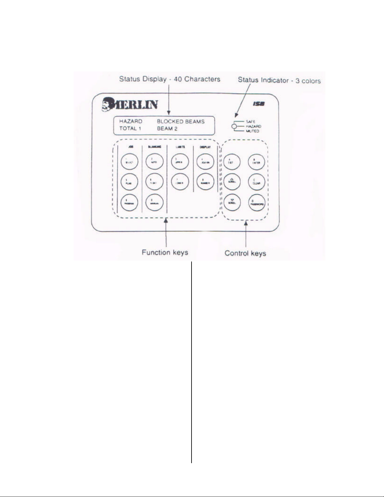
MT3000 FUNCTION AND CONTROL KEYS
1-
2- JOB FUNCTION KEYS
SELECT-Picks a job to run or program.
RUN-Runs a selected preprogrammed job.
PROGRAM-Learns a blanking setup.
BLANKING FUNCTION KEYS
AUTO – Not available.
FLOAT – Activates and selects floating
beams.
MANUAL – Not available.
LIMIT FUNCTION KEYS
UPPER – Lets blanking or float upper
limits.
LOWER – Sets blanking or float lower
limits.
DISPLAY FUNCTION KEYS
LOCATION – Shows broken beam
location or total number.
NUMBER – Shows unit version and size
information.
CONTROL KEYS
EXIT – Quit any function.
ENTER – Acknowledge or change
something.
SCROLL – Display more choices from a
list.
CLEAR – Reset or cancel a numeric
choice.
PASSWORD – To control access to
certain functions.
Page 2
MERLIN 3000 SERIES
B
ENTER
A
EXIT
scroll
scro ll
C
CLEAR
PASSWORD
#
3- VERSION 3.0
The Merlin 3000 series unit is designed for
Press Brake operations especially where
programmable back gauge systems are
used. The Merlin light curtain is useful
when the part to be bent is large enough to
extend into the light curtain beams. It can
be taught the profile of the part when
making the first part. The part profile pattern can then be run from temporary
memory and / or stored for future use.
Only the bottom three inches can be permanently blocked. This allows for a work
support table or arm. The rest of the beams
are not permanently blocked.
! WARNING
WHEN USING BEAM BLANK OUT
FUNCTIONS, CARE MUST BE TAKEN
TO TRAIN THE OPERATORS IN THE
CORRECT METHOD TO HOLD
PARTS SO THAT BOTH HANDS ARE
OUTSIDE THE LIGHT CURTAIN
PLANE AND KEPT AT A SAFE
DISTANCE.
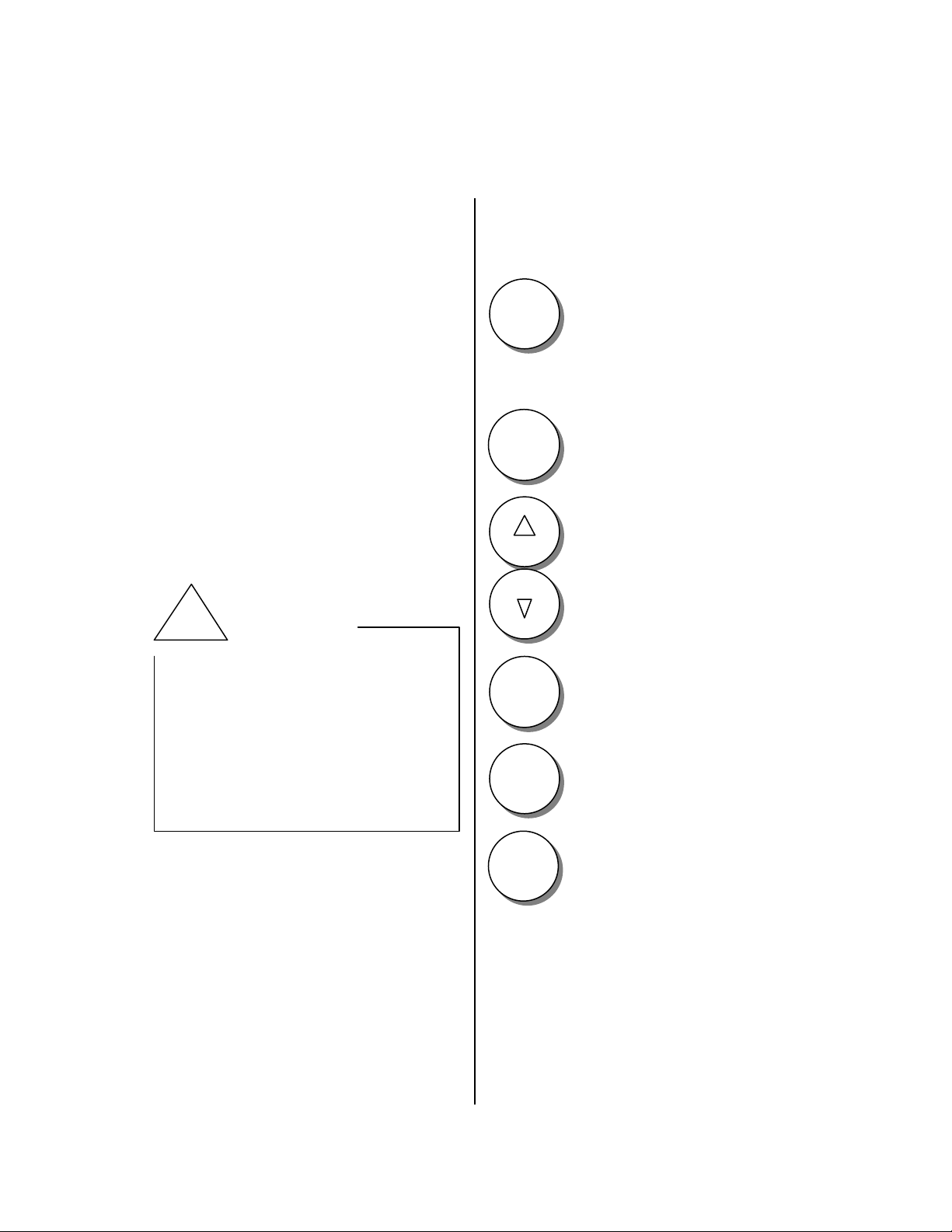
General information about using the Merlin
keypad:
-used to access menu items.
-used to enter numeric
changes made to particular
items.
-used to toggle functions on /
off.
-used to exit out of functions.
-used to scroll through menu
items.
-used to change
numeric values.
-used to scroll through a
program.
-used to clear numeric values.
-used for manual reset.
-used to clear bumping
information.
-used to access setup
information.
-numeric keys have dual
functions. When numeric
entries are valid the numeric
function is active, otherwise
the main label is active.
Page 3
MAIN FEATURES OF THE MERLIN 3000 SYSTEM:
3
UPPER
scroll
scro ll
B
ENTER
A
EXIT
4
Location
EDIT UPPER FLOAT
BEAM XX 1 to XX
LAST LOCATIONS Y
X X X X X
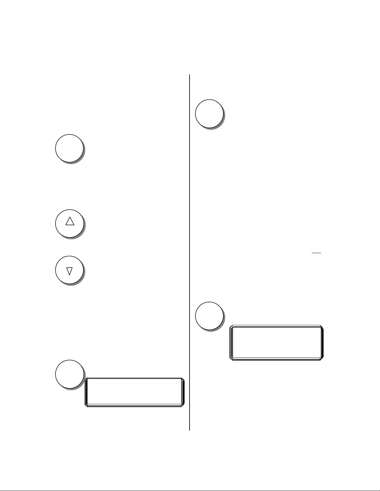
4- LIMITS
These functions are used to display the current limits of the blanking and floating
beam features and to make changes to the
limits.
To display current limits.
This shows the current
floating limit, xx.
Changes the second line to.
Press the UPPER key
Press the SCROLL key
Use the scroll keys to change the current
setting or use the numeric keys to enter the
limit.
Press the EXIT key.
To leave this function, repeat the above
procedure for the lower limits.
5- DISPLAY
When the unit is in a safe condition the
location function will show the last
beam(s) that caused the last hazard
condition. When the unit is in a hazard
condition the location function will show
the current beam(s) not being satisfied. A
beam is not satisfied if it is blocked or not
aligned, or if it has been blanked and is not
blocked.
This shows the current blanking
limit, xx.
To correct limits.
If changes are needed, when at the correct
item, FLOAT or BLANK
current limit maximum range
Press the ENTER key
To use location key.
When in a safe condition.
Y Shows the total number of beams not
satisfied.
X Shows the individual beams not
satisfied.
Press LOCATION key.
48
Page 4
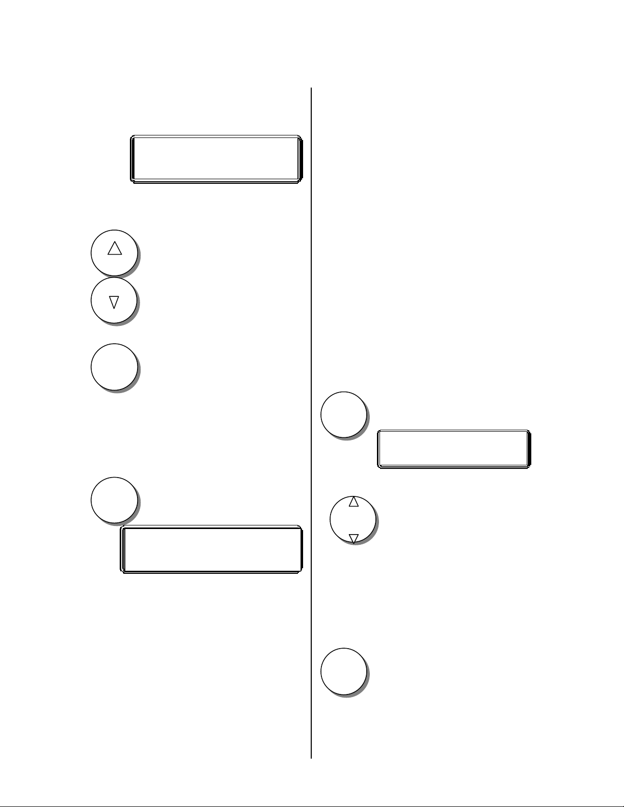
When in the hazard state the following is
scro ll
A
EXIT
8
NUMB ER
6
FLOAT
scroll
C
CLEAR
BEAM LOCATIONS Y
X X X X X
FLOATING BEAMS
VERSION NUMBER 3.XX
XX” UNIT X” BEAM
displayed and updated as the beam
conditions change.
Manual
Manual blanking is not available on
MERLIN 3000 units.
If more than 5 beams are causing the hazard condition, use the SCROLL to view all
of the beams causing the hazard state.
scroll
Press SCROLL key
To return to the previous display.
Press EXIT key
To view the unit version number
and the unit size and beam spacing
information without removing power to the
unit.
Float
The floating beam mode allows one beam
in 1” units and three beams on 1 / 2” units
to be set to float. This means that 1 to 3
beams may be blocked without causing a
hazard condition. Blocking more than the
allowed number will cause the output to of
open, stopping the machinery being controlled. If limits are set for the floating beams
the floating function only works within the
limits. Interrupting any number of beams
outside the limit will cause a hazard
condition.
To activate floating beam(s),
Press FLOAT key
This key can also be used to reinitialize the
display should it get locked up for any
reason.
6- BLANKING
Auto
Auto blanking is not available on Merlin
3000 units.
Press NUMBER key
To change the number of floating beams.
Press SCROLL key
or
To reset the floating function
to zero.
Press CLEAR key
49
Page 5
To activate the change.
B
ENTER
D
PASSWORD
B
ENTER
B
ENTER
A
EXIT
B
ENTER
A
EXIT
1 FLOATING BEAM
CREATE JOB SAFE f
Or
RUN # _______ SAFEf
Press ENTER key
Use the scroll keys to select the desired
function and
When in a safe mode the display will
indicate floating in the second line.
When in the create or run modes floating is
indicators by a small “f” after the word
safe.
Note: It must be remembered that using
floating beams increases the object sensitivity of the sensing field.
7- PASSWORD
Press ENTER key
8- LOCK FUNCTIONS
Floating beam function;
Setting limits;
Job mode;
These functions can be locked
or unlocked (left open). Scroll
to the desired function.
To lock or unlock the function. If locked,
the Merlin control will prompt the user for
the password if access to the function is
attempted. When done with the lock mode
Press ENTER key
-USED TO LOCK AND
UNLOCK FUNCTIONS.
-USED TO CHANGE THE
USER PASSWORD.
-USED TO SET TIMEOUT
FUNCTIONS.
-USED TO TEST INPUTS.
-USED TO RESET THE
SYSTEM WHEN REQUIRED.
To access the above functions
Press PASSWORD key
and enter the four digit default password or
the user password if one was previously
created.
Press EXIT key
Edit password
User password selection.
To edit the user password, enter a new user
password >_ _ _ _ <. You must enter all
four digits. Do not use the
50
Press ENTER key
Press EXIT key
or the
Page 6
C
CLEAR
scroll
A
EXIT
1
SELECT
scroll
B
ENTER
SAFE
HAZARD
Press CLEAR key
Press SCROLL key
in the user password.
SET FUNCTION TIMEOUT
------Timeout for display reset.
This timeout determines the amount of
time allowed in between key entries. If no
key entry is detected within the timeout the
display and mode being used are cancelled
and the SAFE or HAZARD display is
shown. Four choices are available.
Timeout is none - no timeout
Timeout is short - =15 second timeout
Timeout is medium - =50 second timeout
Timeout is long -=100 second timeout
TEST INPUTS
To the input to be tested. “ON” indicates
that the switch is closed and “OFF”
indicates that the switch is open.
Press EXIT key
To leave this mode.
9- JOB MODE
This mode is used to select the various
functions related to created and running
jobs.
*Note: programming blanking in the job
mode is useable.
This key brings up the job menu from
which you can select from the following
six job functions. Use the SCROLL keys
Press EXIT key
------This mode is used to test the eight “8”
possible external input signals.
------EXT-INTR--External interruption;
Press SCROLL key
Active on.
------MAN RESET – Manual reset; Active
on.
To select and
------INPUT A ------ Aux. Input A;
------INPUT B ------ Aux.input B;
------TOS ------------Top of stroke; Active
Press ENTER key
off;
------MUTE --------- Mute point; active on.
------BOS ------------Bottom of stroke;
active on.
------LEARN-------- Remote learn; Active
on.
To access a particular function.
Create Job
Store Job
Recall Job
Bumping Job
Erase Job
Job Info
Page 7

JOB INFO
A
EXIT
B
ENTER
9
PROGR AM
C
CLEAR
A
EXIT
B
ENTER
9
PROGR AM
BUMPING JOB SAFE
CLEAR / CYCLE PRESS
X JOBS OUT OF 243
BUMPING JOB SAFE
PROGRAM / LEARN
CREATE JOB SAFE
STEP 1 READY
CREATE JOB SAFE
STEP 1 PROGRAMMED
When Job information is selected the
number of jobs stored and the total number
of jobs that can be stored will be displayed.
Press EXIT key
When cycling the press brake, the TOS
(top of stroke) input will cancel the
blanking pattern or pressing
Press CLEAR key
To return to the Job menu.
BUMPING JOB
This function is used when processing a
part whose position is difficult to determine
or whose position tends to change from
stroke-to-stroke. The blanking pattern is
taught when the part is in place, and
automatically resets at the top of the stroke.
Using a remote learn foot switch makes it
easy to set the blanking pattern each stroke.
The program key may also be used to teach
the blanking pattern needed.
To access this mode.
Press ENTER key
will cancel the blanking pattern.
See page 52 for more information on
running jobs, muting, etc.
Press EXIT key
To leave this mode.
CREATE JOB
To create a job either temporarily or to be
stored in memory, the same procedure is
used.
at CREATE JOB
Press ENTER key
Position the part in place and
or the remote learn button.
Press PROGRAM key
Insert the part into place for the first bend
or step.
Press PROGRAM key
or the remote learn switch. Each step must
be programmed even if no beams are
blocked if the part is flat.
Page 8

Cycle the press brake or
scroll
9
PROGR AM
A
EXIT
B
ENTER
A
EXIT
A
EXIT
scroll
B
ENTER
CREATE JOB SAFE
JOB # _ _ _ _ _ _ _ _
SAVING NOW
CREATE JOB SAFE
STEP 2 PROGRAMMED
JOB EXISTS * EXIT
RECALL JOB
NUMBER X
Enter a job number from 1 to 8 digits, then
Press SCROLL key
To advance to step 2.
With the part in position for the second
bend
Press PROGRAM key
or the remote learn switch.
Repeat the above procedure for the number
of steps required. When done
Press EXIT key
Press ENTER key
Note; Job number 1 is different from job
number 10000000 is different from job
number 00000001 etc.
This message appears momentarily, then
you will be back at the job menu. If the job
number already exists a message will
appear.
Press EXIT key
to return to the job menu. Select other job
functions or leave the job mode.
To leave the job menu
You can now choose to store the job into
memory or just run it from temporary
memory. It can be stored into memory
anytime before power is turned off or a
new job is created.
STORE JOB
To store a job
to STORE JOB in the menu and
Press SCROLL key
Press ENTER key
Press EXIT key
RECALL JOB
To recall a job when in the job select menu
to the RECALL JOB function and
Press SCROLL key
Press ENTER key
Page 9

54
scroll
B
ENTER
scroll
B
ENTER
B
ENTER
scroll
B
ENTER
scroll
B
ENTER
B
ENTER
A
EXIT
ERASE JOB MENU
> ALL JOBS?
ERASE JOB MENU
> ONE JOB?
JOB # XXXX
RECALLING
JOB # XX
JOB NOT FOUND * EXIT
ERASE JOB
ARE YOU SURE? * ENTER
Press SCROLL key
through the existing job numbers to the
desired job or enter the correct job number
and
and select this option by
Press ENTER key
Selected job has now been placed in the
temporary memory location so that it can
be run.
ERASE JOB
You can erase on or all jobs in memory.
Be sure that you want to erase a job before
entering into this mode. To erase one or
more jobs from memory
Press SCROLL key
through the job select menu until you are at
ERASE JOB.
Pressing ENTER key.
If you wish to erase one job, after pressing
ENTER key.
Press SCROLL key
through the job numbers or enter the
numeric job number that you wish to erase.
Press ENTER key
will appear if the job does not exist. If the
job does exist;
You can
to select this option or
to;
Press ENTER key
Press ENTER key
Press SCROLL key
Press ENTER key
to erase the job or
Press EXIT key
to cancel the erase mode.
Page 10

RUNNING JOB
When running jobs, either step jobs or
bumping jobs, input signals are required for
TOS (top of stroke), MUTE (1 / 4” position), and the BOS (bottom of stroke) functions.
NOTE: The top of stroke position
assumes a down acting press
brake. This is the ram open
position and would be the
bottom position on an up acting
press brake. The TOS and BOS
signals would therefore be
reversed for an up acting brake.
TOS
This signal is active off. The
input is off or open at the top of
the stroke and generally closed
elsewhere.
MUTE
NOTE: If a separate BOS signal is not
available, the mute & BOS
inputs need to be connected
together.
See wiring section for the proper
connections for these inputs.
MUTE: The mute function mutes or
bypasses the light curtain making it
insensitive to obstructions in the sensing
field. It is very important that the set-up
be done carefully so that the muting
occurs when the die is 1 / 4 inch or less
open. The muting is initiated when the
mute input is activated and stays in the
mute mode until the TOS input cancels it.
Two separate timeouts will also deactivate
the mute mode if the TOS signal is not
received. The mute mode will timeout one
hundred (100) seconds after starting if the
mute input is left on, or ten (10) seconds
after the mute signal goes off, whichever
occurs first.
This signal is active on. This is the point at
which the light curtain is muted or
bypassed to allow the part to bend up
through various beams of the light curtain.
This must be set for each set-up to be
where the die is no more than 1 / 4 inch
open.
BOS
This signal is active on. This
signal enables the MERLIN to
step the program when the next
TOS signal is received. If the
bend is not made and the ram is
returned to the top, the program
will not step if the BOS signal
was not received.
The mute function is indicated by the status
LED in the front panel changing to
AMBER and by a mute message on the
display. The mute function is active in the
RUN, CREATE, BUMPING and standard
SAFE / HAZARD modes of operation.
55
Page 11

ISBISB
Recommended procedures for making parts on press brakes.
WARNING: Never place your hands or arms in the
blanked out area of a light curtain while operating
the press brake.
There are basically two types of parts, small parts and large parts that are processed on a
press brake equipped with a light curtain. Small parts do not extend out into the plane of the
light curtain beams, and large parts do extend into the plane of the light curtain beams.
CAUTION: OPERATORS MUST ALWAYS BE TRAINED IN THE PROPER
PROCEDURES FOR SAFE OPERATION OF PRESS BRAKES.
Whenever possible the recommended procedure to process the parts whether small or large
is to fixture the part in place so that it does not have to be held at all, or cycle the press brake
to the point at which the die is no more than ¼ inch open without the part in the die area. This
if often referred to as the stroke stop point. With the press brake stopped at this point, insert
the part into position. The light curtain can be muted at this point so the part if small can be
held as necessary, and if the part is large the light curtain will not interfere with the process
because it can be muted.
By using the above procedure the hazardous portion of the cycle is protected by the active
light curtain and the actual process of bending the material is not hampered by the light
curtain because it can be muted from the point at which the die is ¼ inch or less open,
through the bending portion back to the open position.
Some light curtains require external muting devices to bypass the protection provided by the
light curtain at the ¼ inch point while others have built in muting features. The ISB MERLIN
3000 series has the muting function built into the light curtain.
WARNING: The muting of the light curtain must be adjusted for each set
up so that muting does not occur before the ¼ inch point.
The MERLIN 3000 light curtains also have additional features which assist in the processing
of large parts on press brakes.
In all cases the part should be held with both hands outside the plane of the light
curtain during the hazardous portion of the cycle.
56
Page 12

FLOATING BEAM FEATURE:
The floating beam feature allows one or more beams to be blocked without the output
of the light curtain opening. This feature is useful when holding a large flat part in the
plane of the light curtain. The part may twist or bend slightly possibly blocking a beam.
The floating beam feature allows the part to move in and out of the beam without
shutting down the press brake.
PROGRAMMABLE BLANKING:
Many large parts are processed completely without putting the part down or changing
the set up. This is most often done when using automatic back gauges to reposition the
material stops so multiple bends can be processed. When this is done it is quite
common that a flange bent on a previous step will extend through the plane of the light
curtain blocking one or more beams on a subsequent step. Again, if the part can be
inserted at the ¼ inch position the programmable blanking feature is still not needed. If
the flange is relatively small the floating beam feature may be enough to allow
operation to continue. When it is not enough the programmable beam blank out feature
will allow operation of the press brake with the part in place.
WARNING: Never place your hands or arms
into the area where beams are blanked out
during the hazardous portion of the cycle.
There after the light curtain will blank out the correct beams for each step of the part to
allow it to be in the path of the light curtain beams. The beams that are blanked out
exactly match the shape of the part. The light curtain will not go to a safe state unless
the blanked out beams are blocked by the correct shape of the part.
The programmable blanking feature will
allow the light curtain to learn the shape
of the part the first time the part is made.
The only beams that can be permanently blocked in the standard program are the
bottom three inches of the light curtain to allow for tables or support arms. The other
beams that are blanked out must be active momentarily between strokes to allow the
next blanking pattern to be recalled.
Up to 16 steps can be programmed for each part on the MERLIN.
When using the programmable blanking feature it is helpful to activate the floating
beam feature after programming the entire part to allow slight mis-positioning of the
part without creating a stop signal.
57
Page 13

CAUTION: NEVER PLACE YOUR HANDS OR ARMS INTO THE DIE AREA OF
THE PRESS BRAKE. WHEN ONE OR MORE BEAM(S) IS NOT ACTIVE KEEP
BOTH HANDS OUTSIDE THE PLANE OF THE LIGHT CURTAIN BEAMS.
BLANKED BEAMS ARE ONLY FOR THE PART TO BE IN POSITION.
Follow the procedures in the manual to check for the proper operation of the light
curtain prior to operating the press brake and / or after every set up.
The light curtain must be mounted at the correct safety distance as per the safety
distance formula considering no beams are blanked out.
If you have any questions concerning the correct use of the programmable light curtain
features call ISB for assistance.
58
Page 14

Troubleshooting
Symptom
No hazard or safe indication.
CHECK / CAUSE
General for all models
• Input wiring to correct terminals.
• Input fuse.
• Proper voltage.
Hazard indication only.
Safe indication but machine won’t run.
Occasional blinks to hazard.
• Proper alignment of TX and RX.
• Separation distance RX to TX excessive.
• Proper cable connections to TX and RX.
• Cable connector locking ring not in
detent.
• Relay failed. (M2000 and M3000 units
have a relay failure message).
• On multiple column systems master
columns, (RX and TX) must be first from
the control, Model # CMxxx.
• Output wiring at TB2-1,2,3,4.
• Fuses for Relay 1 and 2.
• Relay out of it’s socket.
• Marginal alignment of TX and RX.
• Cable connector locking ring not in
detent.
• Vibration of mounting brackets causing
misalignment.
• RX or TX cable close to high voltage.
• Marginal connection on opto boards in
columns.
Merlin 1000
Unit works but LED on door doesn’t.
Unit goes to hazard when interrupted and
stays in hazard. Power down/up resets unit.
Unit doesn’t work, blue and amber leds in TX
column on.
• Wiring harness to door unplugged.
• Relay contacts worn or sticking. Replace
relays.
• TX and RX cables swapped.
59
Page 15

Merlin 2000 and 3000 common symptoms
Merlin 2000 standard messages are “SAFE and HAZD #”. The number after HAZD
indicates the total number of beams not satisfied.
Pressing the “Location” button when in the Hazard state, changes the display to show
“BEAM #”. The number shows which beams are not satisfied starting at the first (closest to
the control box) beam. Using the “Scroll” buttons allows viewing of all of the beams not
satisfied.
Merlin 3000 standard messages are “SAFE and HAZARD Blocked Beams, Total #
Beams #” The total number and which ones not satisfied are shown.
Beams are not satisfied if they are blocked and not blanked, or if they are not blocked when
blanked.
If the number of beams indicated as not satisfied equals the total number of beams the unit
may be completely mis-aligned or the TX cable and or connector may be loose, off or
damaged.
Merlin 2000 and Merlin 3000
Unit works but LED and display on door
doesn’t.
Unit goes to hazard when interrupted and
stays in hazard. Relay fail message. Power
down/up resets unit.
Blanking functions not working properly.
Floating function not working properly.
Cannot access blanking, floating or job
functions.
Display gets lost or partial messages.
Key pad doesn’t work, display does.
• Wiring harness to door unplugged.
• Relay contacts worn or sticking. Replace
relays.
• Limits are set wrong.
• Too many beams trying to be blanked.
• Blanked beams must remain blocked.
• Limits are set wrong.
• Floating function used for another beam
that is blocked and not blanked or one
that is blanked and not blocked.
• Function locked in password section.
• Auto and manual blanking not available
on Merlin 3000 units.
• Output wiring close to display when door
closed.
• Noise interference. Install suppressor on
AC input terminals.
• Defective program chip on display board.
• Key pad wire harness disconnected from
PC Board on door.
• Bad program chip on display board.
•
Page 16

Merlin 3000
No muting at ¼ “ point.
• Mute input signal not on.
• Top input signal not on. ( TOS is active
off, at the top/open position).
Use Test Inputs mode in password to check
input status.
Unit won’t step through program created.
• Missing BOS signal.
• Part? displayed. Permanent beam
blockage above allowable beam point.
The standard program allows only the
bottom 3 inches to be permanently
blocked.
Look for table or part support arms too high.
Won’t learn beam blockage.
• Limits are set wrong.
• Too many beams blocked.
• Not in the create mode.
Stays in hazard at one or more steps.
• One or more beams not satisfied; either
blocked when it shouldn’t be or not
blocked when it should be.
• Turn on floating function to allow minor
part misplacement.
Remote learn doesn’t work.
• Remote input not coming on.
Use Test Inputs mode in password to check
input status.
61
Page 17

Display messages including error messages and their causes;
Most of the messages that appear during normal functions are not listed here
because they are easily understood. Refer to the manual for help.
Merlin 2000
SAFE All beams satisfied. Output contacts closed.
HAZD # # = the number of beams not satisfied, Output contacts open.
SAFE B Auto or manual blanking active with all beams satisfied.
SAFE F1 Floating blanking active.
SAFE BF1 Auto or manual blanking active with all beams satisfied.
Floating blanking active.
FAIL RLY Failed relay. One relay failed or sticking when outputs open.
NO COLU No column. This indicates that the RX column is not being sensed.
Cables may be swapped.
FAIL CLM Column failed. Generally a problem in the RX column.
WRONG This indicates the wrong password was entered.
Merlin 3000
SAFE All beams satisfied. Output contacts closed.
HAZARD Blocked Beams
Total # Beams #
Total number of beams not satisfied is shown with the beam
number(s) scrolling. Output contacts open.
SAFE by Muting
Output contacts closed. Unit is muted. Blocking beams will not
open the output contacts or stop the machine.
WAIT This indicates that the RX column is not being sensed. Cables may
be swapped.
Relay Failure
# _ Contacts
Failed relay. One relay failed or sticking when outputs open.
Noise Retry
Noise Error
Very marginal beam alignment when Learning a blanking pattern.
Try realigning the TX, RX columns.
Shutdown by External The output contacts are forced open when the External interrupt
input is activated on by the machine control.
Step 0 Ready The CREATE mode was not properly exited. Enter into and exit
from the CREATE mode. Should say “Step 1 Ready” when
creating a new program.
62
Page 18

Recommended spare parts/
Replacement parts
MTC1000 -Merlin 1000 T Series Control Box
MTC2000 -Merlin 2000 T Series Control Box
MTC3000 -Merlin 3000 T Series Control Box
Replacement Cables:
55-5xx-02-00 2 ft.
55-5xx-05-00 5 ft.
55-5xx-10-00 10 ft.
55-5xx-15-00 15 ft.
55-5xx-25-00 25 ft.
55-5xx-35-00 35 ft.
55-5xx-50-00 50 ft.
22-222 Output Relay
Page 19

INFARED SECURITY BARRIERS
WARRANTY
ISB warrants the products it manu-
factures to be free from defects in
material and workmanship provided
these defects are not caused by abuse,
accident, or neglect, and agrees to correct
by repair or replacement of the part, or
parts, any such defect disclosed on
examination by us and which
development under normal installation,
use and service for a period of 3 years
from the date of shipment to the original
purchaser when the equipment is
returned to our service facility.
Normal wear on the relay output contacts
is not covered under this warranty, as it is
not considered a defect.
ISB does not assume responsibility for
unauthorized repairs to apparatus even
though defective.
This warranty is in lieu of all other
warranties expressed or implied, and no
representative or person is authorized to
assume for us any liability in connection
with the sale of our products.
ISB shall not be liable for consequential
damages. All equipment returned to ISB
for warranty service must be sent prepaid.
ISB will not accept collect freight
shipments. Any equipment returned to
out factory under this warranty shall be
returned UPS, Ground or Truck prepaid.
Authorization to return material must be
first obtained from one of out branch
offices, or from one of out Sales
Department.
For additional information, repair or
service, contact your local ISB distributor
or:
ISB Div. 3517110 Canada inc.
2300 Victoria Ave.
Lachine Qc. Canada H8S 1Z3
Tel.: (514) 637-7000 Fax.: (514) 634-9868
ISB Services Inc.
Phone (866) ISB-LITE
64
 Loading...