

Page 1

gomerlin.com.au
gomerlin.co.nz
MR855EVO
Garage Roller Door Opener
Installation and Operating Instructions
Owners Copy: Please keep these instructions for future reference
This manual contains IMPORTANT SAFETY information
DO NOT PROCEED WITH THE INSTALLATION UNTIL READING THE
INSTRUCTIONS THOROUGHLY
Page 2

Warranty Registration
To validate your warranty you must complete
the registration form online at:
gomerlin.com.au/warranty
or
gomerlin.co.nz/warranty
Page 3
START BY READING THESE IMPORTANT SAFETY INSTRUCTIONS
WARNING
•Failuretocomplywiththefollowinginstructionsmayresultin serious injuryorproperty damage.
• Read and follow all instructions carefully.
• The garage door opener is designed and tested to offer safe service provided it is installed and
operated in strict accordance with the instructions in this manual.
These safety alert symbols mean WARNING : A possible risk to personal safety or
property damage exists.
Keep the garage door balanced. Do not let the
garage door opener compensate for a binding or
sticking garage door. Sticking, binding or
unbalanced doors must be repaired before
installing this opener.
Do not wear rings, watches or loose clothing
while installing or servicing a garage door
opener. Wear gloves and suitable protective
clothing where appropriate.
Frequently examine the door installation. In
particular examine cable, springs and mountings
for signs of wear, damage or imbalance. Do not
use if repair or adjustment is needed since springs
and hardware are under extreme tension and a
fault can cause serious personal injury.
To avoid serious injury from entanglement,
remove all ropes, chains and locks connected
to the garage door before installing the door
opener.
Installation and wiring must be in compliance
with your local building and electrical codes.
The safety reverse system test is very
important. Your garage door MUST reverse on
contact with a 40 mm obstacle placed on the
floor. Failure to properly adjust the opener may
result in serious injury from a closing garage
door. Repeat the test once a month and make
any necessary adjustments.
This appliance should not be used by children or
persons with reduced physical, sensory or mental
capablities, or a lack of experience & knowledge,
unless they have been given supervision or
instruction concerning use of the appliance by a
person responsible for their safety.
The opener must not be used on a wicket
door (door within a door).
The Protector SystemTMmust be used for all
installations where the closing force as
measured on the bottom of the door is over
400 N (40 kgf). Excessive force will interfere
with the proper operation of the safety reverse
system or damage the garage door.
After installation, ensure that the parts of
the door do not extend over public
footpaths or roads.
Install the wireless wall control (or any
additional wall control) in a location where
the garage door is visible away from
moving parts, at a height of at least 1.5 m
and out of the reach of children. Do not
allow children to operate push buttons or
transmitters. Serious personal injury from a
closing garage door may result from misuse of
the opener.
Permanently fasten the warning labels in
prominent places, adjacent to wall controls
and manual release mechanisms as a
reminder of safe operating procedures.
Activate opener only when the door is in
full view, free of obstructions and the
opener is properly adjusted. No one should
enter or leave the garage while the door is
in motion.
Do not allow children to play near the door
or with door controls.
If the power cable is damaged, it must be
replaced by the manufacturer, its service
agent or similarly qualified persons in order to
avoid hazard.
Automatic Drive - Keep away from the area of
the door as it may operate unexpectedly.
This opener should not be installed in a damp
or wet space exposed to weather.
NOTE: If your garage has no service entrance door, we recommend an outside quick release must be installed.
This accessory allows manual operation of the garage door from outside in case of power failure.
CONTENTS PAGE
SAFETY INSTRUCTIONS . . . . . . . 1
CARTON INVENTORY . . . . . . . . . .2
TOOLS REQUIRED . . . . . . . . . . . .2
DOOR REQUIREMENTS . . . . . . . .2
CONTROL PANEL . . . . . . . . . . . . . .3
PREPARE & TEST THE DOOR . . .4
PINNING THE DOOR . . . . . . . . . . .5
OPERATING MANUAL RELEASE .5
INSTALLATION PROCEDURE . . . .7
ADJUSTMENT & TESTING . . . . . .8
INSTALL THE PROTECTOR
SYSTEM . . . . . . . . . . . . . . . . . . . .10
AUDIBLE BEEP . . . . . . . . . . . . . . .11
PARTIAL OPENING . . . . . . . . . . . .11
WIRELESS PROGRAMMING . . . .12
STANDBY MODE (OPTIONAL) . .12
OPERATING YOUR OPENER . . .13
CARE OF YOUR OPENER . . . . . 13
MAINTAINING YOUR OPENER . . 13
SPECIFICATIONS . . . . . . . . . . . . .13
WIRING . . . . . . . . . . . . . . . . . . . . .14
TROUBLESHOOTING . . . . . . . . .15
ACCESSORIES . . . . . . . . . . . . . . .16
DIAGNOSTIC CHART . . . . . . . . . .17
WARRANTY . . . . . . . . . . . . . . . . .18
Disconnect electric power to the garage
door opener before making repairs or
removing covers.
KEEP THESE INSTRUCTIONS
1
Page 4
1
13 mm, 10mm, 8 mm
5.5 mm
Marker Pen
8
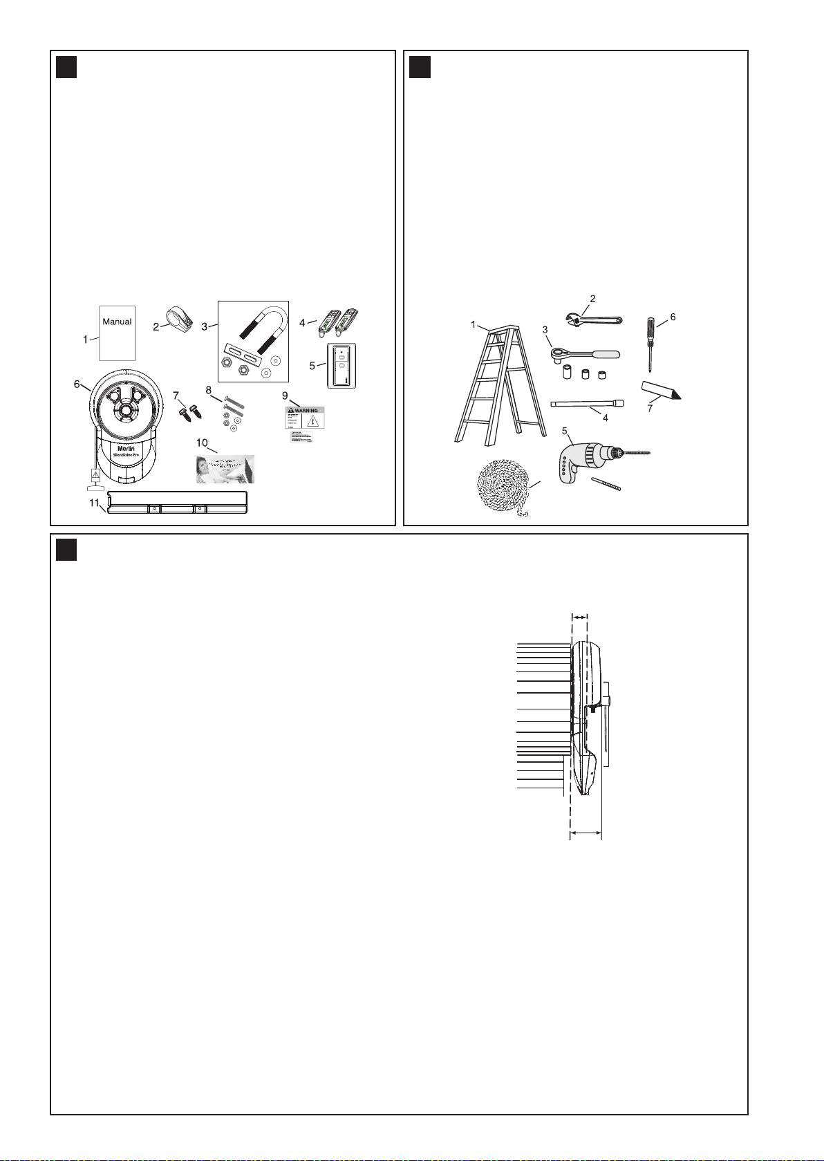
95 m m
Minimum distance from
edge of curtain to edge of
door bracket 45 mm
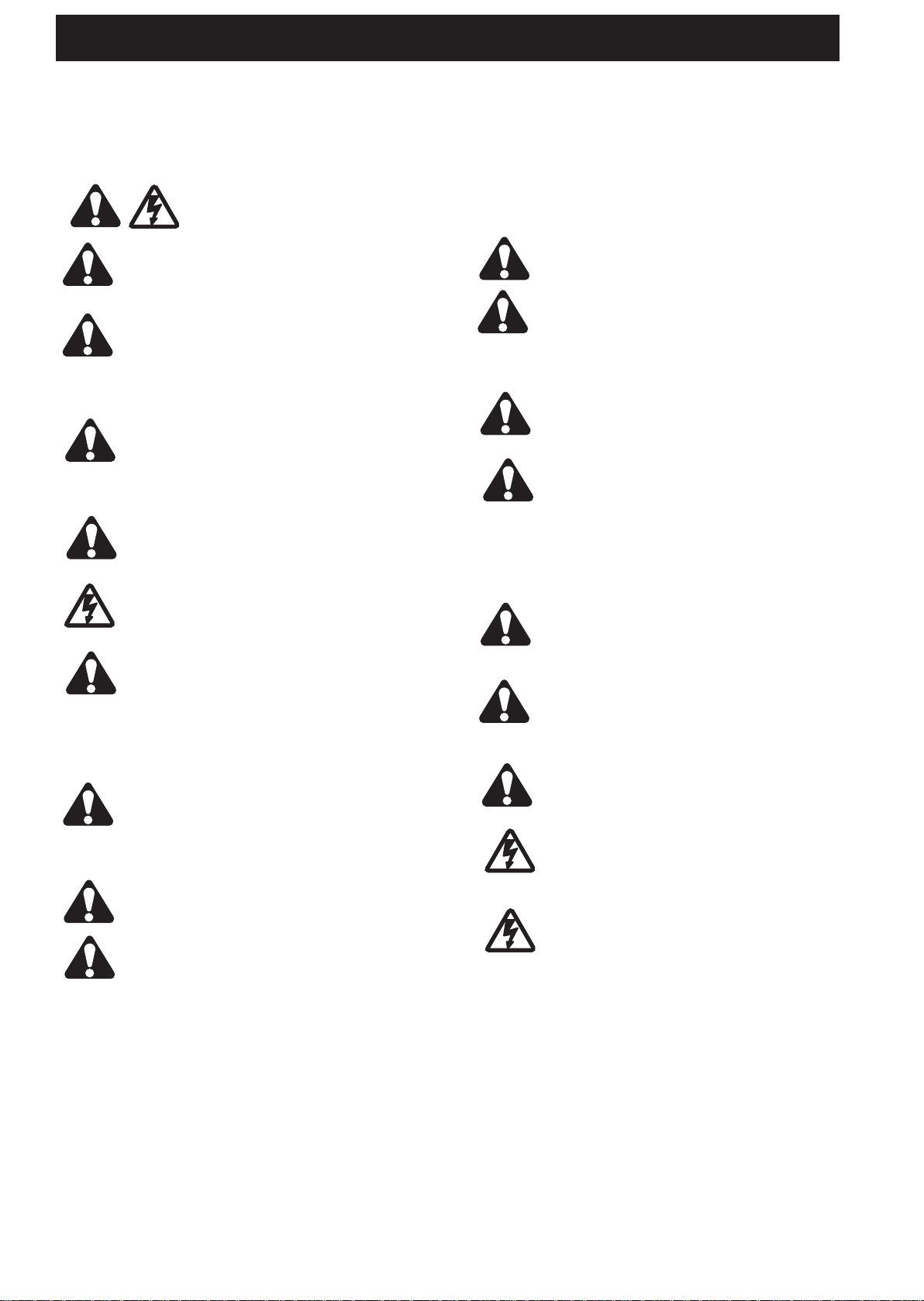
CARTON INVENTORY
TOOLS REQUIRED
2
1. Instruction manual (this document)
2. Stop collar
3. Clamp bracket, plates, washers (2) and nuts (2)
4. E960M Premium transmitter (2)
5. E138M wireless wall button (1)
6. Opener
7. Self tapping screws (2) (for pinning the door)
8. Weight bar screws (2), washers (2) and nuts (2)
9. Warning label and risk of entrapment label
10. Warranty registration card
11. Weight bar
1. Ladder
2. Adjustable wrench for U-bolts already installed
on the door
3. 8 mm socket, 10 mm socket and 13 mm extended
socket and socket wrench
4. 300 mm socket extension (for minimum side-room
installations)
5. Drill and 5.5 mm drill bit
6. Philips-head screwdriver
7. Marker pen
8. Rope
9. Door stand (not shown)
3
DOOR REQUIREMENTS
The SilentDrive Pro (MR855EVO) is suitable for spring
balanced Residential Rolling garage doors with:
• Maximum door height of 4.5 m
• Maximum curtain area of 18 m
2
• Maximum door mass of 120 kg
*The obstruction detection beams must be installed if
the force at the edge of the closing door exceeds 400
N (40 kgf).
Door axle diameter must not exceed 35 mm.
Ensure that there is at least 45 mm from the edge of the curtain to the edge of the bracket. If the roller door
drum wheel is on the edge of the curtain or is a smaller diameter, additional clearance may be required.
Assemble the opener to the door axle and the existing door bracket using the U clamp assembly provided.
Tighten to 25-28 Nm. Full installation process is in section 13.
2
Page 5
DN
UP
P
S
6
6
1
2
3
7
A
B
C
B
D
2
3 4
5
8
1
DN
UP
1
2
3
P
S
1
A
B
C
B
D
8
2
3 4
5
6
6
7
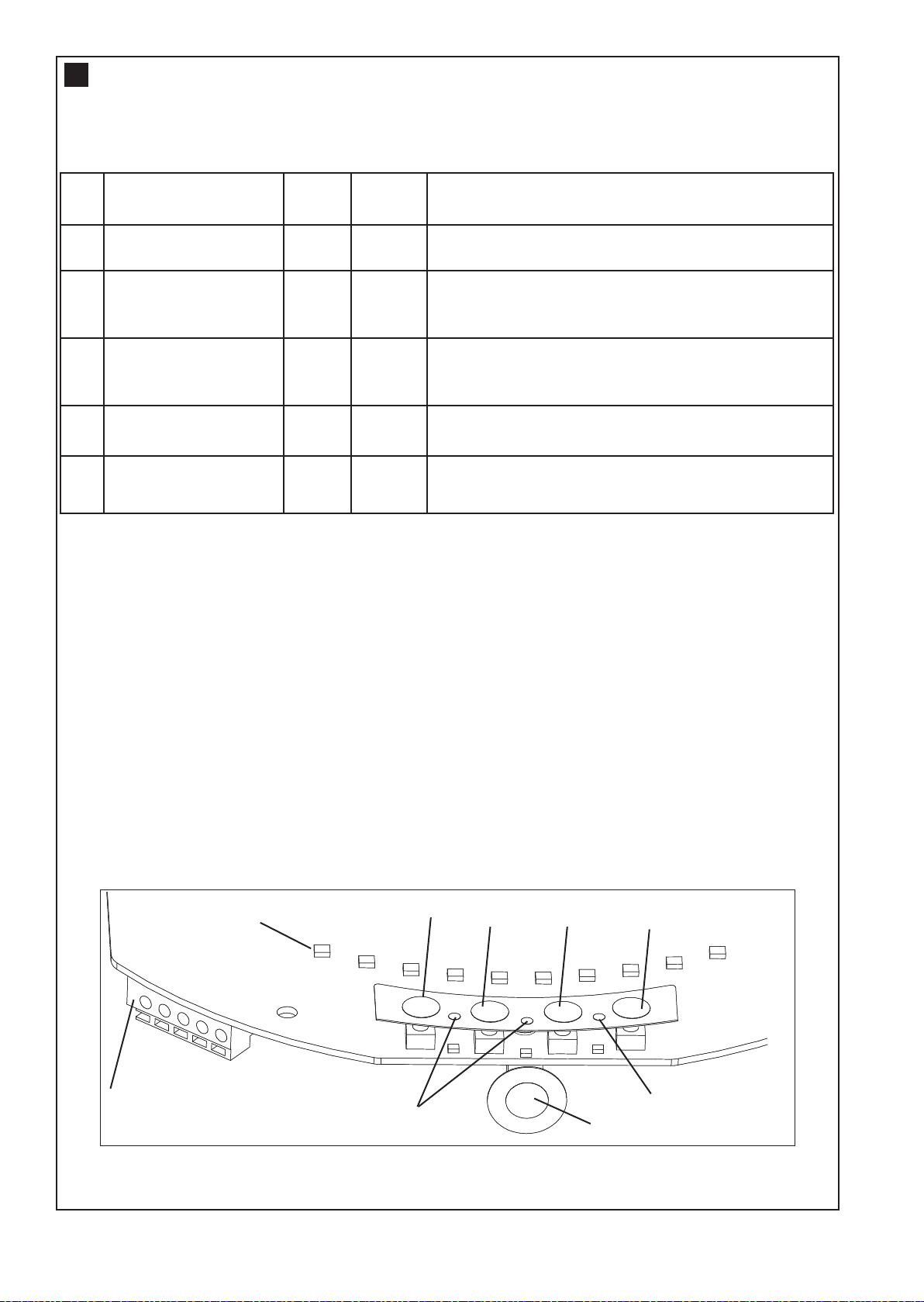
CONTROL PANEL
4
1. Terminal Block: used for external accessories (see chart below).
Ref Function
Push button
A
Common
B
B Common White -ve Common terminal for push button, obstruction
C Obstruction Detection
Beams
Accessory Power
D
NOTE: The terminal block is behind a plastic cover in the back housing. Use a small screwdriver to lever
open the plastic cover if access to the terminal block is required. All wires should be secured appropriately.
2. DN Button: used to drive the door DOWN
Colour
Red
White
Grey
Green
Polarity Comment
+ve
-ve
+ve
+ve
Dry contact input for push button wired wall
controls
Common terminal for push button, obstruction
detection beams & accessory power
detection beam & accessory power
Obstruction detection beam Input (pulsing
type only) - see section 17
24v dc 50 mA accessory output available for a
universal receiver (output not active in Standby Mode)
3. UP Button: used to drive the door UP
4. P Button: used to “PROGRAM” the DOOR LIMITS (see section 14)
5. S Button: used to “SAVE” and “DELETE” the “REMOTE CONTROLS” (see section 21)
6. LEDs: 1. Program DOWN, and Diagnostic code indicator Number 1
2. Program UP indicator
3. Diagnostic code indicator Number 2
7. Control Button: Used to activate the door when remote controls are not available. Open - Stop - Close.
8. Courtesy Light: turns on during operation and automatically turns off after a period of 3 minutes
3
Page 6
5
Non opener side
Opener side
Boss
1
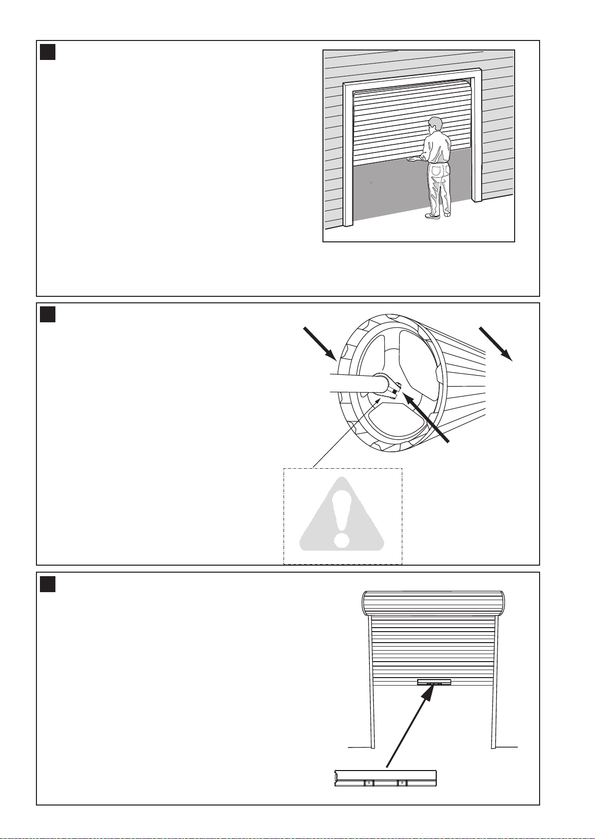
TESTING THE DOOR
Complete the following test to ensure your door is well
balanced, and not sticking or binding:
• Disable all locks and remove any ropes connected to the
garage door.
• Lift the door to about halfway and then release it. The
door should remain spring balanced.
• Raise and lower the door to determine if there are any
sticking or binding points (20 kgf is the absolute maximum
allowable to raise or lower the door in any position).
If your door does not hold in place or the door binds or
sticks, call a qualified door technician before installing the
opener.
6
ATTACHING THE STOP COLLAR
• The stop collar is required to be installed on the
opposite side of the door to where the opener is to be
installed.
• Ensure the U-Bolt holding the door shaft to the door
bracket is tightly secure.
(NOTE: This U-Bolt must not be removed or loosened)
• Remove the bolt assembly from the plastic stop
collar. Open the collar as wide as possible and push
it onto the door shaft.
• Fit the stop collar hard against the boss of the
door drum. Reinstall the bolt assembly onto the
stop collar and tighten.
ATTACHING THE WEIGHT BAR
7
If the door has a lifting handle, remove the handle, nuts &
bolts. Place the weight bar over the handle holes, insert the
extended bolts through the weight bar & fasten the handle
back in place.
• Place the weight bar in the centre of the door as shown.
Is the stop collar installed?
YES: proceed to the next
NO: install the stop collar
SAFETY CHECK!
step
before proceeding
If the door curtain does not have a handle you will need to
follow these instructions:
• Use a marker pen to mark the two hole positions.
• Drill two 5.5 mm holes through the two marked
positions, then place the weight bar on the inside of the
door.
• Use the bolts, washers and nuts (provided) to
fasten the weight bar in place.
4
Page 7

Rope
Manual release
warning label
Release handle
Overhand knot
Rope
Manual release
warning label
Release handle
Overhand knot
8
PINNING THE DOOR
Note: A ballooning door may delay the safety reversal
response and can compromise garage door security.
• To remedy any ballooning, insert the supplied self tapping
metal screws into where the curtain leaves the roll. Secure
these through the curtain into the drum wheel at each end
of the roll.
• After determining the correct fastener location as shown, lift
the door approximately half a turn from the closed position
to allow access for securing the screws.
9
THE RELEASE HANDLE & CORD
Do not disengage the opener to manual operation
with children, persons or other objects including
motor vehicles within the doorway. The door is
under significant tension and if the door has developed a fault
or incorrect tension, it may be unsafe and may fall rapidly.
Free curtain
Door closed
Ballooning
Door can be
lifted
Add fasteners here
Door secure
The manual release mechanism enables the door to be
manually operated during power outages or in an emergency.
The RED Manual Release cord is preassembled to the
opener. When the opener is installed the handle should be no
higher then 1.8 metres from the floor. The cord may need to
be extended for high door installations.
OPERATING THE MANUAL RELEASE
10
To disengage the opener
Pull the release cord down firmly,
(the opener will make a clicking noise).
To re-engage the opener
Pull the release cord down firmly,
(the opener will make a clicking noise).
Disable all locks and remove any ropes connected to the garage door.
Take care when operating the manual release as an open door may fall rapidly due to weak or
broken springs, or being out of balance.
5
Page 8

Extension pole
Reinforcing Brace
11
ATTACHING EXTENSION POLES (IF REQUIRED)
Optional accessory not provided
• Insert the extension poles into the drive legs.
• Align the holes on the extension poles with the holes
on the drive legs
• Using the screws provided, secure the extension poles
• Align the holes of the reinforcing brace with the two
holes on the end of the drive legs as shown and fix in
place using the screws provided. Please note that the
reinforcing brace MUST be applied.
12
LEFT
(handing must
be changed
during limit
setting - refer to
section 14)
Reinforcing brace must be used. Use
extension pole kit part number 002A1828
LEFT / RIGHT HAND INSTALLATION
RIGHT
(factory
default
setting)
Inside garage looking out
6
Page 9

Rope
Ladder
Rope
Ladder
13
INSTALLATION PROCEDURE
Do not allow people to walk under or
around the door during the installation
process as serious injury can occur.
NOTE: The opener can be installed on either side
of the door. The following instructions are for
RIGHT HAND INSTALLATIONS (as illustrated i.e.
inside the garage looking out). For left hand
installations, reverse the instruction terminology
(eg LEFT for RIGHT etc).
Preparation:
• Place the opener in manual release mode (refer to
section 10)
• Completely open the roller door. For safety,tie a rope
around the door
• Ensure the door axle U-BOLT and door mounting
bracket on the left hand side (non opener side) are
securely fastened
• Support the door with a door stand, ladder or similar
device to safely support the door
• Mark the position of the door shaft on the right hand
door bracket (for reassembly purposes)
• While the door is supported, remove the right hand
axle U-Bolt and door mounting bracket from the wall
Install the opener:
• Slide the opener over the door axle and engage the
drive legs into the door drum wheel, either side of a
spoke
• Refit the door mounting bracket to the wall
• Clamp the opener on the door axle and door bracket
in the marked position using the clamp assembly
supplied (tighten to 25 – 28 Nm)
• Remove all ropes and the support stand
• Check the operation of the door in manual mode by
raising and lowering by hand. It should operate
smoothly without sticking or binding. The disengage
handle should already be attached less than 1.8m
above the floor
Connect the power:
• Position the power cable away from the door curtain
and any moving parts
• Plug the opener into a nearby power point and turn
ON
• The opener light will turn ON and remain ON for 3
minutes
Tighten to
25-28 Nm
7
Page 10

14
132A2940
1. Program
Start
2. Left/Right
Setting
3. Accept
Setting
4. Set UP
Limit
5. Accept UP
Limit
6. Set DOWN
Limit
7. Accept
DOWN
Limit
8. Learn UP
Force
9. Learn
DOWN
Force
Flash x2
BEEP
DOWN
DOWN
UP
UP
DNDN
UP
UP PP
S
S
1
1
2
2
3
3
Flash x2
BEEP
DNDN
UP
UP PP
S
S
1
1
2
2
3
3
DNDN
UP
UP PP
S
S
1
1
2
2
3
3
DNDN
UP
UP PP
S
S
1
1
2
2
3
3
Flash x2
BEEP
DNDN
UP
UP PP
S
S
1
1
2
2
3
3
Flash x2
B
E
EP
DNDN
UP
UP PP
S
S
1
1
2
2
3
3
Full light
BEEP
DNDN
UP
UP PP
S
S
1
1
2
2
3
3
Flash x 2
BEEP
DNDN
UP
UP PP
S
S
1
1
2
2
3
3
Flash x 2
B
EEP
DNDN
UP
UP PP
S
S
1
1
2
2
3
3
Travel limits set how far your door goes up and down. Your opener must also be configured for right or left hand
installation. If not the door will rotate in the reverse direction.
Program Buttons: The Control Panel diagram in section 4 identifies the Control Buttons and LED layout
Audible Beep: An audible “BEEP” also occurs with each button press. This feature can be turned OFF
Courtesy light: During the programming sequence, the courtesy light will flash at half strength
NOTE: The SilentDrive Pro (MR855EVO) opener is factory configured for right hand installation.
Setting the Right or Left Hand Operation:
Refer to the diagrams on the right for guidance.
Ensure the door is positioned halfway and the opener is
engaged (out of manual mode).
Turn the opener Power ON, the courtesy light will turn ON.
1. Press the “P” button for 5 seconds until LED 3 will flash,
2. To change to the opposite setting, simply press the “S”
3. When the correct hand setting is selected, Press and
SETTING THE LIMITS FOR RIGHT OR LEFT HAND OPERATION AND FORCE
The opener will operate during this procedure. Make sure the door is clear of obstruction.
Ensure your hands are away from any moving parts before activating the door.
as well as LED 2 or LED 1 will flash. For Right Hand
setting LED 2 will flash, and for Left Hand setting LED 1
will flash.
button, and the opposite LED will flash.
Release the “P” program button to accept this
setting. (continue)
Setting the Door Limits:
4. Press and hold the “UP” button until the door
5. Press and release the “P” program button to
6. Press and hold the “DN” button until the door
7. Press and release the “P” program button to
Setting the Force Automatically:
8. Press and release the “UP” button. The door will travel to
9. Press and release the “DN” button. The door will travel to
Setting the Force manually: (Only perform if Limits are
already set)
• Start with the door fully CLOSED.
• Press the “S” button twice to enter into force learn mode.
• Press and release the “UP” button. The door will travel to
• Press and release the “DN” button. The door will travel to
reaches the desired OPEN position (You can toggle
between the “UP” and “DN” buttons to move the door to
the correct position. Make sure there is enough room
for your vehicle to pass under)
accept this setting.
reaches the desired CLOSED position (You can
toggle between the UP and DN buttons to move the
door to the correct position.)
accept this setting. (LED 2 should flash to indicate
you are now in Force Learn mode) (continue)
the OPEN position with LED 2 flashing.
the CLOSED position with LED 1 flashing. When fully
closed, LED 1 will stop flashing and the courtesy light will
change to full power.
(This process is now complete)
The Courtesy light will go to half strength, and LED 2 will
flash quickly.
the OPEN position, then LED 1 will flash quickly.
the CLOSED position, then LED 1 will stop and the
courtesy light will change to full power.
This process is now complete.
8
Page 11

Handle should be
less than 1.8 m
<1.8 m
15
40 m m Test obst acle
40 mm
+
TESTING THE SAFETY REVERSE SYSTEM
The safety reverse system test is important.
The garage door must reverse on contact
with a 40 mm obstacle laid flat on the floor.
Failure to properly adjust the opener may result in
serious personal injury from a closing garage
door.
Operate the door in the down direction. The door must
reverse upon contact with the obstacle. If the door
stops on the obstacle, remove obstacle and repeat
limit and force setting (refer to section 14).
Repeat the safety reverse system test.
FIXING WARNING LABELS
16
Once you have completed your installation and
successfully carried out the safety reverse system
test (outlined above), install the warning labels
provided with your opener as shown.
The risk of entrapment label must be installed
adjacent to the release handle at a height of less than
1.8 m from the floor.
The WARNING label must be installed in a prominent
place near any fixed control.
Any fixed wall control or wireless door control must be
mounted at a height of no less than 1.5 m out of the
reach of children.
Read the safety instructions (page 1) for further
details concerning safety.
INSTALLING YOUR E138M WIRELESS WALL BUTTON
17
Disconnect power to the opener whilst installing
this accessory to prevent accidental activation.
Locate minimum 1.5 m above the floor
To install:
• Carefully pry open the E138M and locate the two screws for
mounting.
• Attach to the wall using the two screws and wall anchors
provided if mounting to a plaster wall. If using a recessed wall
box do not use anchors.
NOTE: Do not overtighten screws.
NOTE: The wall control supplied with your opener should be pre-programmed by the factory.
If adding a new wall control, program into the opener before mounting the unit as detailed in
the “Wireless Programming” in section 21.
STANDARD INSTALLATION COMPLETE
9
Page 12

18
ACTIVATE
TIMER TO
CLOSE
SET
TIME
ACCEPT
SETTING
Flash x 2
BEEP
DNDN
UP
UP PP
S
S
1
1
2
2
3
3
BEEP
DNDN
UP
UP PP
S
S
1
1
2
2
3
3
Flash x 2
BEEP
DNDN
UP
UP PP
S
S
1
1
2
2
3
3
INSTALLTHE PROTECTOR SYSTEMTM(OPTIONAL ACCESSORY)
NOTE: This accessory must be used for all
installations where the closing force as measured
on the bottom of the door is over 400 N (40 kgf).
After the opener has been installed and adjusted, the
Protector System™ can be installed. Instructions are
included with this accessory.
The Protector System™ provides an additional
measure of safety against a small child or animal
being trapped under a garage door. It uses an infra-
red beam, which when broken by an obstruction,
causes a closing door to stop and open, preventing an
open door from closing and is strongly
recommended for homeowners with young
children or pets.
ENABLING THE PROTECTOR SYSTEM:
• Connect the obstruction detection beam wiring to the opener and turn ON. (The obstruction detection
beams will automatically enable once they are connected and will now operate in a FAIL SAFE mode.)
DISABLING the obstruction detection beams:
If the obstruction detection beams are installed and needs to be removed the opener will need to be
reprogrammed.
Perform the power ON/OFF sequence as follows
• Remove the obstruction detection beam wires from the opener
• Turn the mains power OFF for 5 seconds
• Turn the power ON for 5 seconds
• Turn the power OFF for 5 seconds
• Turn the power ON and check the opener operates OK without the obstruction detection beams
SAFETY FIRST!
Whilst Merlin have engineered safety features into your garage door opener, we urge you to
consider fitting obstruction detection beams to your new garage door opener. In many countries
these devices are compulsory to assist in preventing serious injury or property damage. For your
own peace of mind and the safety of others please consider installing this safety device.
Timer to close feature (TTC)
Auto close is NOT recommended for households with young children.
TIMER TO CLOSE feature: (TTC) 10 to 180 seconds.
NOTE: The Protector SystemTMMUST be installed before TTC will operate.
The Timer to Close feature allows the door to automatically close after a specified time period. During the
OPEN door waiting period, the courtesy light will flash continuoulsy.
If the door encounters an obstruction while closing, the opener will
return to the OPEN position and the waiting period will begin again.
To activate the Timer to Close:
• Start with obstruction detection beams installed and the door fully
CLOSED
• Press and Hold both “P” and “DN” buttons for 3 seconds. When the
Courtesy light flashes “TWICE”, release both buttons
• Press the “UP” for each 10 second interval required for
Timer to Close. A “BEEP” will register for each press. “DN” button
will reduce the count if needed.
• Press and release the “P” button to accept this setting
To deactivate the Timer to Close:
• Start with the door fully CLOSED
• Press and Hold both “P” and “DN” buttons for 3 seconds. When the
Courtesy light flashes “TWICE”, release both buttons.
• Press and release the “P” button to accept this setting
The door may operate unexpectedly, therefore do not allow anything to obstruct the path of the
door.
10
Page 13

BEEP
AUDIBLE
BEEP
Flash x 2
BEEP
DNDN
UP
UP PP
S
S
1
1
2
2
3
3
19
fig.3
Flash
x 2
Door Fully Closed
fig.1
fig.2
BEEP
DNDN
UP
UP PP
S
S
1
1
2
2
3
3
Flash
x 1
BEEP
DNDN
UP
UP PP
S
S
1
1
2
2
3
3
AUDIBLE BEEP (OPTIONAL)
The SilentDrive Pro (MR855EVO) has been
factory set for an audible “BEEP”.
The Audible beep can be turned OFF by using the
following method.
• Start with the door fully CLOSED.
• Press and Hold both “S” and “DN” buttons
for 3 seconds
• The Courtesy light will flash “TWICE”.
Release the buttons.
To turn the audible beep back ON, simply repeat the
above process.
VENTILATION MODE - PARTIAL OPENING FEATURE
20
This is an adjustable, second stop position, that can be preset, partially open for ventilation, pedestrian or pet access,
programmed to the Remote Control.
To activate the ventilation mode:
1.Start with the door fully CLOSED (figure 1). Drive the
opener UP and stop at the position required for you wish to
set the door at.
2.Enter ventilation activation mode by pressing the P and UP
buttons together for 3 seconds (figure 2). Release when the
courtesy light flashes once.
3.Press the remote control button that you have allocated for
this feature (figure 3). Do not use the button already
allocated for normal operation. The courtesy light will flash
when the code is accepted.
The remote will now operate to and from the “programmed” and
the “fully closed position”. Outside this range the remote will
operate as normal.
To deactivate the partial opening feature:
1.Start with the door fully CLOSED.
2.Enter ventilation mode by pressing the P and UP buttons
together for 3 seconds (figure 2). The courtesy light will
flash twice, indicating that deactivation has occurred.
11
Page 14

WIRELESS PROGRAMMING (REMOTE ACCESSORIES)
Flash x 10
NORMAL
STANDBY
LOW
STANDBY
BEEP
DNDN
UP
UP PP
S
S
1
1
2
2
3
3
Flash x 1
BEEP
DNDN
UP
UP PP
S
S
1
1
2
2
3
3
1
2
Flash x 2
BEEP
DNDN
UP
UP PP
S
S
1
1
2
2
3
3
or
21
NOTE: The transmitters supplied with your opener are preprogrammed by the factory.
Activate the opener only when door is in full view, free of obstruction and properly adjusted.
No one should enter or leave the garage while the door is in motion. Do not allow children to
operate push buttons or remotes. Do not allow children to play near the door.
If you purchase additional transmitters, the garage door
opener must be programmed to accept the new remote
code.
Program the receiver to match additional transmitter
codes:
Using the “S” SAVE Button
1.Press and hold the button on the remote that you wish
to use (1)
2.Press and release the “S” button on the opener (2)
3.Release the remote button when the courtesy light
flashes twice. It has learnt the code. If you release the
remote control push button before the opener light
flashes, the opener has not learnt the code.
The opener will now operate when the remote control button is pressed.
To Erase all Remote Control Codes
1.Press and hold the “S” button on the opener until the courtesy light flashes twice, and continue
holding for approximately 8 seconds, until the courtesy light flashes twice again.
2.Release the button, all codes are now erased.
STANDBY MODE (OPTIONAL)
22
The SilentDrive Pro has been factory set for low
standby mode (sub 1 watt usage).
This will deliver the lowest possible standby power. The
External Accessory Power is turned OFF in this mode,
so if this output is required, Normal Standby mode will
need to be activated (eg. for using an external receiver).
To Activate NORMAL STANDBY mode:
• Turn the mains power OFF.
• Press and Hold both “UP” and “DN” buttons.
• Turn ON mains power while both buttons are
still pressed.
• Courtesy light comes ON, and after 5
seconds another 10 flashes. Release both
buttons.
To Activate LOW STANDBY mode:
• Turn the mains power OFF.
• Press and Hold both “UP” and “DN” buttons.
• Turn ON mains power while both buttons are
still pressed.
• Courtesy light comes ON, and after 5
seconds another 1 flash. Release both
buttons.
12
Page 15

OPERATION OF YOUR OPENER
Your opener can be activated by any of the following
devices:
• Opener Control Panel: UP & DOWN buttons, and
O.S.C. control button.
• Remote Control Transmitter: hold the button
down until the door starts to move.
• Wireless Entry Keypad: This is an accessory that
opens the door using a four digit keycode.
When the opener is activated:
• If open, the door will close. If closed, the door will
open
• If closing, the door will stop
• If opening, the door will stop (allowing space for
entry and exit of pets and for ventilation)
• If the door has been stopped in a partially open or
closed position, it will reverse direction
CARE OF YOUR OPENER
When properly installed, your opener will operate with
minimal maintenance. The opener does not require
additional lubrication.
Limit and Force Settings: These settings must be
checked and properly set when the opener is installed.
Weather conditions may cause some minor changes in
the door operation, requiring some re-adjustments,
particularly during the first year of operation. Refer to
limit and force setting in section 14.
Follow the instructions carefully and repeat the
safety reverse test after any adjustment.
Transmitter:Additional transmitters can be purchased
at any time. Refer to gomerlin.com.au or
gomerlin.co.nz for compatible transmitters. Any new
transmitters must be programmed into the opener.
Transmitterbattery: If the transmission range
decreases, replace the battery.
Obstruction behaviour:
• If an obstruction is encountered while closing, the
door will reverse
• If an obstruction is encountered while opening, the
door will reverse and stop
• Obstruction detection beams use an invisible beam
which, when broken by an obstruction, causes a
closing door to open and prevents an open door
from closing. It is STRONGLY RECOMMENDED
for homeowners with young children or pets.
Opening the door manually:
When releasing the door, the door should
be fully closed if possible. Weak or
broken springs could allow an open door
to fall rapidly. Property damage or
serious injury could result.
The door can be opened manually by pulling the
release cord down firmly.
To re-engage the door, pull the release cord down
firmly.
The opener light will turn on for 3 minutes when
the opener is activated.
MAINTENANCE OF YOUR OPENER
Once a Month:
• Repeat the safety reverse test (see section 15).
Make any necessary adjustments.
• Manually operate the door. If it is unbalanced or
binding, call for professional garage door service.
• Check to be sure that the door opens and closes
fully.
Set the limits and/or force if necessary.
SPECIFICATIONS SILENTDRIVE PRO
(MR855EVO)
Input Voltage: 220-240 VAC, 50-60 Hz, 140 W
Rated Load: 35 Nm
Max.Pull Force: 550 N @ O300 mm
Max. door weight: 120 kg
Max lift under Spring Tension: 20 kg
Max. door area: 18 m
Standby Power: <1 watt
Drive: DC gear motor permanent
Max. Drum Rotations: 4
Memory Registers: 64
Operating Frequency: 433.30/433.92/434.54 MHz
Operating Temperature: 550C to -250C
2
lubrication
1/
2
SPECIAL NOTE: Merlin strongly recommends that obstruction detection beams be installed on all garage door
openers.
13
Page 16

white
black
24 vdc
com
External
Receiver
Wired Wall Button
com
n/o
4 3 2 2 1
Obstruction Detection Beams
green (4) grey (3) white (2) red (1)
23
or
Carefully
RemoveBatter y
(CR2032x 1)
1
2VDC
Pb Cd Hg
TYPICAL WIRING DIAGRAM SILENTDRIVE PRO (MR855EVO)
Information for Service Personnel
24
REPLACE BATTERIES IN REMOTES
Battery of the remote control:
The batteries in the remote have a long life.
If the transmission range decreases, the batteries should be replaced. Batteries are not covered by the warranty.
To prevent SERIOUS INJURY OR DEATH: observe the following instructions for the battery
- NEVER allow small children near batteries.
- If battery is swallowed, immediately notify a Doctor.
- Danger of explosion if battery is replaced improperly.
- Replacement only by identical or equivalent type.
- Dispose of old battery properly. Batteries should not be treated as household waste. All consumers
are required by law to dispose of batteries properly at the designated collection points.
- Never recharge batteries that are not meant to be recharged.
- Do not short-circuit batteries or take them apart.
- If necessary, clean contacts on batteries and contacts before loading.
- Never expose batteries to excessive heat such as sunshine, fire or the like!
Replacing battery (CR2032 or equivalent):
To replace the battery, turn the
remote control around and open
the case with a screwdriver. Lift
the cover and lift the control board.
Slide the battery to one side and
remove the old battery. Be sure to
observe the polarity of the battery.
Assemble the transmitter again
following the steps in reverse.
14
Page 17

25
TROUBLESHOOTING
1. The opener will not operate from either the
UP/DOWN activation button or the transmitters :
• Does the opener have electric power? Plug a lamp into
the outlet. If it does not work, check the fuse box.
• Have you disabled all door locks? Review the
installation safety instruction warnings on page 1.
• Is there a build-up of ice or snow under the door? The
door may be frozen to the ground. Remove any
restriction.
• The garage door spring may be broken. Have it
replaced by contacting a garage door repairer.
2. Opener operates from the transmitter, but not
from the wired wall control terminals:
• Check that the wiring connections are correct.
3. The door operates from the UP/DOWN activation
buttons but not from the wireless wall control or
transmitter:
• Program the opener to match the transmitter code.
Repeat with all transmitters.
4. The transmitter has short range:
• Change the location of the transmitter.
• Check to be sure the antenna on the bottom of the
opener extends fully downward.
• Some installations may have shorter range due to a
metal door, foil backed insulation, or metal garage
siding.
• The batteries may be flat. Replace the batteries.
5. The garage door opens and closes by itself:
• Be sure that no transmitter buttons are being pressed.
• Clear the memory and re-program all wireless wall
controls and transmitters.
8. The door opens but will not close (or reverses
while closing):
• Is something obstructing the door? Pull the manual
release handle. Operate the door manually. If it is
unbalanced or binding, call a trained door systems
technician.
• Clear any ice or snow from the garage floor area where
the door closes.
• Repeat the limit and force setting. Repeat safety reverse
test after adjustments.
9. The opener strains to operate the door:
• The door may be out of balance or the springs may be
broken. Close the door and use the manual release to
disconnect the door. Open and close the door
manually. A properly balanced door will stay in any
point of travel while being supported entirely by its
springs. If it does not, disconnect the opener and call a
trained door systems technician.
10. The opener motor hums briefly, then will not
work:
• Check that the door is not in manual release mode
(refer to sections 9 or 10).
• The garage door springs may be broken.
• If the problem occurs on the first operation of the
opener, the door may be locked. Disable any door
locks.
11. The opener will not operate due to a power
failure:
• Use the manual release handle to disconnect the door.
The door can be opened and closed manually. When
power is restored, re-engage the opener to operate it
via a transmitter.
6. The door reverses and stops before opening
completely:
• Is something obstructing the door? Is it out of balance,
or are the springs broken? Remove the obstruction or
repair the door.
7. Door reverses for no apparent reason and
opener lights flash 10 times:
• Check the obstruction detection beams (if you have
installed this accessory). If the red light on the beam is
flashing, the alignment is incorrect.
• The red light on the beams may not be on if the
opener is in Standby mode. Activate the door to
temporarily exit standby mode and check lights are on
constantly. If the LEDs are flashing, realign the beams.
12. The LED Indicators on the control panel are
flashing in sequence:
• Check the diagnostic code in section 28.
15
Page 18

ACCESSORIES
4
5
6
11
7
9
8
3
1
10
2
002A1873
Weight bar
002A1977
Front lower housing assembly
002A1956
Sungear assembly
093A0809
Upper housing
002A1867
Sub 1 watt PCB
204A0301
Transformer
002A1959
APE assembly
014A1395
PCB assembly
002A1958
Chassis sub-assembly
002A1960
Stop collar
093A0808
Base housing
002A1874
RDO clamp
026A0189
Power cord
26
1. Model E138M 2 Channel wireless wall button
2. Model E960M 4 Channel Premium transmitter
3. Model E950M 4 Channel transmitter
4. Model E940M 1 Channel transmitter
5. Model E943M 3 Channel transmitter
7. Model E840M Keyless entry system
8. Model 760AML Outside keyswitch
9. Model CM1702 Outside quick release (steel fix)
10. Model DMK1 Outside quick release (brick fix)
11. Model 774ANZ The Protector System
TM
(IR Beams)
6. Model E945M 3 Channel mini transmitter
NOTE: Use of any Chamberlain Group accessories are approved to use with this opener. This includes genuine
Merlin accessories. Generic compatible accessories are NOT approved for use with this opener.
27
SPARE PARTS
16
Page 19

DIAGNOSTIC CHART
28
Your garage door opener is programmed with self-diagnostic capabilities. The indicator LEDʼs 1 & 3 on the control panel will flash a number of
times to indicate a fault code exists.
DIAGNOSTIC CODE
LED 1 LED 3
11
12
13
14
15
21
22
SYMPTOM
The garage door opener will not
close and the courtesy light flashes.
The garage door opener will not
close and the courtesy light flashes.
The door control will not function.
The garage door opener will not
close and the courtesy light flashes.
There is no door movement or motor
accelerates before stopping
suddenly.
Opener fails to operate.
Opener fails to operate.
POSSIBLE RESOLUTION
Safety sensors are open circuit or wires may be cut. Inspect sensor wires for a
disconnected or cut wire. Turn power off and reboot the opener.
There is a short circuit wire for the safety sensors. Inspect safety sensor wire
at all staple points and replace wire or correct as needed. Turn power off and
reboot the opener.
The wires for the door control are shorted or the door control is faulty. Inspect
safety sensor wire at all staple points and connection points and replace wire
or correct as needed.
Safety sensors are misaligned or were momentarily obstructed. Realign both
sensors to ensure both LEDs are steady and not flickering. Make sure nothing
is hanging or mounted on the door that would interrupt the sensors path while
closing.
No RPM pulses have been detected. Check the door manually for balance,
binding or obstructions. Internally the possible cause may be the motor, logic
board or RPM sensor. Try resetting door travel limits. Contact service centre.
Possible PCB memory failure. Reboot opener by turning the mains power OFF
and then ON after 15 seconds. Reprogram the door travel limits and force
settings. Contact service centre.
Possible PCB Voltage failure. Reboot opener by turning the mains power OFF
and then ON after 15 seconds. Reprogram the door travel limits and force
settings. Contact service centre.
24
41
4 2
Opener fails to operate using the
remote controls
Door is moving down, stops and
reverses.
Door is moving up, stops and
reverses.
Possible receiver failure. Reboot opener by turning the mains power OFF and
then ON after 15 seconds. Recode the transmitters. Contact service centre.
Manually open and close the door. Check for binding or obstructions, such as
a broken spring or door lock. If the door is binding or sticking contact a trained
door systems technician. If door is not binding or sticking, reset the limits (refer
to “Program the Travel Limits and Force” section).
Manually open and close the door. Check for binding or obstructions, such as
a broken spring or door lock. If the door is binding or sticking contact a trained
door systems technician. If door is not binding or sticking, reset the limits (refer
to “Program the Travel Limits and Force” section).
17
TM
Tra dem a rk of Th e C ham be rlain Group, Inc.
® Re g istered Tra d em ark of T he Ch a m berlain G rou p, Inc.
© 2017 The Chamberlain Group, Inc
Page 20

CHAMBERLAIN LIMITED WARRANTY
Merlin®Professional SilentDrive®Pro MR855EVO
Roller Garage Door Opener
Cha m be rla in Austra lia Pty Limite d / C h a m b e rlain New Ze a lan d Lim ite d
(Chamberlain), th e m anufactu rer of M erlin®auto m a tic ga rag e do or
openers, is c o m m itted to m anufactu rin g and sup p lyin g high q u ality g oods.
As p a rt of this c o m m itm ent, w e see k to p rovid e reliable se rvic e and supp o rt
fo r o u r g oods a n d are pleased to p rovide you, the orig inal purchaser, w ith
th is C ham b erlain Lim ited W arra n ty.
The b enefits given to y o u un der th is C ham berlain Limite d Warra n ty a re in
additio n to any rights an d rem edies th at y o u m ay h a v e un der A u stralian o r
New Zeala nd con s u m er p rotection laws. O u r g oods co m e w ith g uara nte e s
th a t c a n n ot b e excluded u n d er th e A ustralian C onsu m er La w, or N ew
Zealand C onsum er G u a ra n tess Act 199 3 . You are e n title d to a rep lacem ent
or re fu n d for a m a jor fa ilu re a nd for com p ensation for any other reasonably
fo resee a b le loss or d a m ag e . You a re a lso e n title d to h ave the g o o d s
re p aired o r rep laced if the g oods fail to be of accep table quality a nd the
fa ilu re d oes no t am oun t to a m a jor fa ilu re.
Chamberlain’s warranty
What is covered
Cha m be rla in w arra n ts to the o rig ina l purchaser of the M erlin SilentD rive P ro
M R 855E VO Roller D o o r O pen e r (U n it) that all pa rts of th e Unit, oth e r than
re m o te c o n trolled tra n sm itters, b a tte ry ba c k up un its and ac ce s s o rie s,
glo b e s and ba tte ries, a re free fro m defects in m ate rials a nd w ork m an s h ip for
a pe rio d of 84 m o n ths o r 1 5,0 0 0 cy c les (each o penin g & closin g of the
garage d o o r e quals 1 c y c le) w h ichever com es first, from the d a te o f
purchase w hen insta lle d by a P ro fessio nal d e ale r a p p oin ted o r a uth o rised
by C ham b erlain in a resid ential p re m ise w ith a residen tia l spe c ified g a rage
door that is de s igned for the sole purpose o f a single -fam ily dw ellin g .
Cha m be rla in w arra n ts that th e rem o te co n trolled tra n s m itters (E 9 6 0M )
in cluded w ith the U nit a re free fro m defects in m ate rials an d workma n s h ip
fo r a pe riod o f 2 4 months fro m th e date o f pu rchase an d all o th e r
accessories inclu d ed w ith the U nit are fre e fro m defects in m ate rials a nd
workm anship for a p e riod o f 1 2 months fro m th e da te o f p u rchase.
What is not covered
Batte rie s and globes a re n o t c o v e re d un der th e Cham berlain Lim ite d
W a rranty.
Tra v e l costs incurred b y C h am b e rlain or the P ro fe s s ional De a ler in eith er
travellin g to or fro m areas ou tsid e a capital city m etrop o litan a rea. The s e
costs will be at the p u rchase r ’s expense .
Additional access costs in curred by a P ro fe s s ional Dea ler or C h a m b e rlain in
obta ining acce s s where the Unit is no t readily a c c e ssible. T h e se cost w ill be
at the pu rchaser’s ex p ense.
Warranty Conditions
It is a co n d ition of this C ham berla in L im ite d Warra n ty that th e Unit is sold ,
in stalled a n d se rv iced b y a P rofessional D ealer appointe d or a u th o ris e d by
Cha m be rla in. A M erlin branded ga rage do o r o pener purchased o ver th e
in ternet a nd insta lled by a p ers o n other th a n a P rofe s s ional De a ler w ill not
be co v e red by this Cham b e rlain Lim ite d W arran ty.
It is also a condition of this Chamberlain Limited Warranty that for the
operating life of the Unit:
1 the garage door is spring balanced, is operable by hand and opens
and closes with no more than a maximum of 20 kg of lifting weight;
2 the g a rag e do or a nd the U nit is profe s s ionally m ainta ined a n d se rv iced
by a Professio n a l D eale r, a t a min im u m , d u rin g the third a n d fifth years of
th e Cham berlain Limited Warran ty p e rio d such that th e sp ring balanced
door ope rates accordin g to m an u facture r s p e cification s . If y o u r d oor
bin d s , s ticks, or is out of bala nce, th e n it m u s t n o t b e used until serviced
by a tra ined d oor te c h nician or P rofesio n a l D eale r. T h e ga rage do o r
serv ice fee w ill b e at the p u rc h a ser’s e x p e nse;
3 the w arra n ty is registered by c o m p leting the o nline form at
w
ww.gomerlin.com.au or www.gomerlin.co.nz; a n d
4 yo u retain you r s a les d o c k e t o r invoic e as proo f o f pu rchase, and atta ch it
to this manua l to enab le yo u to e s tablish the d a te of pu rchase in the
unlikely ev e n t o f a warran ty servic e be ing requ ire d.
Making a claim
Durin g the a pplicable Cham berlain Limited Warran ty p e rio d, if you a re
concerned that th e Unit m ay b e defective, call the P rofessio n a l D eale r that
sold /in s talled the o pener, or ou r s e rvic e ce n tre o n the toll fre e nu m b e r b elo w
and a Cham berlain te chnic ian w ill d iagnose the problem an d arrange for this
to be rectified .
O n c e the p rob lem has been diagnosed , sub ject to y o u r rights un d e r the
applicable Australian an d New Ze ala n d co n sum e r p ro tection law s with
re s p ect to m ajor fa ilu res, C h a m b e rlain or its P rofe ssional Dea ler will provide
you w ith eith e r, repairs to the U nit or a repla cem e n t U nit.R epa irs an d
re p lace m en t pa rts provided un d er th is C ham b erlain Lim ited W arra n ty a re
pro vide d free of charge a n d are warranted for th e rem a ining po rtion o f the
origin al w arra n ty p e riod.
114A5021B
This Cham berlain Lim ite d Warra n ty p rovides ben e fits w hic h are in a d d ition
to yo u r o th e r rig hts an d rem edies as a co n s u m e r.
Exclusions - what voids the warranty
If ou r s e rvic e ce ntre d e te rm ine s that a w arran ty claim has be e n mad e in
re s p ect o f a failure or defect arisin g under or out of any e x c lusio n de ta ile d
belo w such that th e claim is no t c o v e red un d e r this C h a m b e rla in Lim ite d
W a rranty, w e m ay, s u b ject to yo u r o th e r rig hts an d rem edies as a
consum er, charge you a fee to repair, replace and /or retu rn the U nit to
you.
This Cham berlain Lim ite d Warra n ty d o e s not cove r a n y failure of, o r
defe ct in, th e Unit d u e to:
1 non-c o m p lia n c e with the instruction s regardin g sp e cificatio n s ,
in stallation, operation, m ain tenance an d testing of the U nit or of an y
pro duct with which the Unit is us e d ;
2 any atte m pt by a perso n other than a Pro fessio n al D ealer to repa ir,
dism antle , rein s tall o r m ove the U nit to ano ther lo cation o n c e it has
been insta lled;
3 use of any c o py, im itatio n or replica g ara g e do o r rem otes w ith yo u r
M e rlin U nit;
4 tam perin g , n e g lect, a buse, we a r a n d tear, accid e n t, electric a l storm ,
excessiv e us e or c o nditio n s other than n o rm al dom estic use;
5 pro b lem s w ith , o r relating to, the ga rage do o r o r g a ra g e do o r h a rd w are,
in cludin g but n o t lim ited to the d oor springs, doo r rollers, d o o r
alignm ent or hin g e s;
6 pro b lem s cause d by electrical faults o r replacem e n t o f b a tteries or light
bulb s , b low n fuses, ele ctrica l surges, pow e r s u rg e s or p owe r strikes,
fire , flo o d , rain, w ater, lig h tning or storm s;
7 water o r m o istu re ingress that c a uses corrosion or e lectric a l
m a lfu nction;
8 corrosio n cause d by se a air if locate d near a w ate rw a y, beach e tc;
9 fitm ent to a com m e rcia l d o o r o r in a co m m ercial operating a p plication,
in stallation o f a resid ential garage do o r o p ener in a com m e rcia l o r
in d u s trial prem ises o ther than a single -fa m ily dw elling .
10 lack of proper m ain tenan c e , se rvic e or c a re of the d o o r a nd U nit;
11 an y un a uth o rised m odific a tio n to the U nit; o r
12 d a m a g e ca u sed by insects , pe s ts or o ther after sa le da m ag e ca u s e d
by eve n ts o r a c c idents outside Cham b e rlain ’s reasonable contro l a n d
not arisin g under norm a l an d standard o p e ra tin g cond itions.
NB : A G e neral P u rp o se O utlet (G P O ) ie : p o wer po int m u s t b e su p plied by
th e co n sum e r a s this e lectrical fitting d o e s no t form a p art o f the U nit
(o p ener).
If this Cham b e rlain Lim ite d W arran ty do e s no t a p p ly, y o u may h a ve rig h ts
available to y o u under th e A ustralian an d New Ze a lan d co n s u m e r
pro te c tio n law s .
Liability – Australia only
Except as s e t o u t in the Austra lia n Consum er Law (be ing S chedule 2 of
th e Competition and Consumer Act 2010) (as a m e n d e d, c o nsolidate d or
re p lace d ):
1 all oth er guarante es, w arra n ties and representations in relatio n to the
Unit o r its su p p ly a re ex c luded to the e xte n t that Ch a m b e rla in can
la w fu lly ex c lude them ; a nd
2 under no c irc u m s tances w ill C ham berlain be liable for c o nsequentia l,
in cidental o r sp e c ial d am a ges aris ing in conn e c tio n with the u s e , o r
in a b ility to u se , the U nit, oth e r than those w hic h were reasonably
fo resee a b le a s lia b le to result fro m the failure.
Liability – New Zealand only
Except as s e t o u t in the Fair Trading Act 1986 and the Consumer
Guarantees Act 1993 (a s am e n d ed, consolidated or repla c e d):
1 all o ther gu a rantees, wa rranties a n d representations in rela tio n to the
Unit o r its su p p ly a re ex c luded to the e xte n t that Ch a m b e rla in can
la w fu lly ex c lude them ; a nd
2 un d er no circu m stances w ill C ham berlain be liable for con se q u ential,
in cidental o r sp e c ial d am a ges aris ing in conn e c tio n with the u s e , o r
in a b ility to u se , the U nit, oth e r than those w hic h were reasonably
fo resee a b le a s lia b le to result fro m the failure.
Note
Cha m be rla in reserves the rig h t to c h a n ge the d e s ign a n d specifications o f
th e Unit w ithout prior no tifica tio n . Som e features or accessorie s of the
Unit m ay no t be av a ila b le in certa in m a rkets or areas. P le a s e ch e ck w ith
your dis tributor.
Chamberlain service centre contact details
Australia
Phon e toll fre e 1800 63 8 23 4
Fax toll fre e 1800 88 8 12 1
W e bsite: g om e rlin.com .a u
New Zealand
Phon e toll fre e 0800 65 3 66 7
Fax toll fre e 0800 65 3 66 3
W e bsite: g om e rlin.co.n z
Em ail: c u sto m erservice@ cha m berla inanz.com
CChhaammbbeerrllaaiinn AAuussttrraalliiaa PPttyy.. LLttdd..
Unit1 , 75 Epping Road
North R yde N S W 2 113
(P O BO X 144 6 , Lane C o v e N SW 1595 )
 Loading...