

Merlin MGL400-24, WingMate 4, MGL400-24S Owner's Manual
MGL400-24 & MGL400-24S
WingMate 4
SWING GATE OPENER
O W N E R ' S M A N U A L
The MGL400-24 is intended for use with vehicular swing gates.
For residential applications only (refer to page 2 for more details).
DESIGNED FOR PROFESSIONAL INSTALLATION
Serial # Primary Arm
Serial # Secondary Arm
Serial # Control Box
Installation Date
NB:
Some references/drawings in this manual relate to international markets


TABLE OF CONTENTS
SAFETY 1-6
Safety Symbol and Signal Word Review 1
Installation Classifications 2
Safety Installation Information 3
Gate Construction Information 4
Important Safety Information 5-6
INTRODUCTION 7-8
Operator Specifications 7
Carton Inventory 7
Additional Items Needed for Installation 8
Wiring Specifications and Tools Needed 8
INSTALLATION 9-19
Overview of Typical Installation 9-10
Check Your Gate 11
Mounting Options 11
Manual Release 12
Determine Position of the Pull-to-Open Bracket 12
Assemble Gate Post Bracket (Pull-to-Open) 13
Attach Brackets to Gate Operator 13
Determine Mounting Location 14
Measuring and Marking for the Gate Bracket 14
Position Gate Operator on Gate 15
Test Gate Travel 16
Secure Post Bracket to Gate Post 16
Secure Gate Bracket to Gate 17
Warning Sign Placement 17
Standard Control Box 18-19
WIRING 20-25
Connect the Gate Operator (Gate 1) to the Control Box 20
Set the Bipart Delay (Model MGL400-24S Only) 21
Connect the Gate Operator (Gate 2) to the Control Box (Model MGL400-24S Only) 22
Junction Box (Model MGL400-24S Only) 23-24
Earth Ground Rod Installation (Optional) 25
Connect Batteries 25
ADJUSTMENT 26-30
Set DIP Switch 26
Limits 27-29
Force Adjustment 30
Timer-to-Close 30
PROGRAMMING 31
Remote Controls 31
Keyless Entry 31
Erase All Codes 31
Test 31
ADDITIONAL FEATURES 32-35
Control Inputs 32
Loop Inputs 33
Photo/Edge Inputs (P 6-7-8 and 9) 33
Safety Accessories for Secondary Entrapment Protection 34
OPERATION AND MAINTENANCE 36-37
Reset Button 36
Remote Control 36
Maintenance 37
Manual Release 37
TROUBLESHOOTING 38-41
Basic Control Board Layout 38
Wiring Diagram 39
Diagnostic Codes 39
Troubleshooting Chart and Tips 40-41
REPAIR PARTS 42-43
Control Box 42
Gate Operator Arm 42
ACCESSORIES 43
WARRANTY POLICY 44
TEMPLATE BACK COVER
SAFETY » SAFETY SYMBOL AND SIGNAL WORD REVIEW
When you see these Safety Symbols and Signal Words on the following pages, they
will alert you to the possibility of
not comply with the warnings that accompany them. The hazard may come from
something mechanical or from electric shock. Read the warnings carefully.
When you see this Signal Word on the following pages, it will alert you to the
possibility of damage to your gate and/or the gate operator if you do not comply
with the cautionary statements that accompany it. Read them carefully.
IMPORTANT
• BEFORE attempting to install, operate or maintain the operator, you must read
and fully understand this manual and follow all safety instructions.
• DO NOT attempt repair or service of your gate operator unless you are an
Authorized Service Technician.
NOTE
Serious Injury or Death
if you do
MECHANICAL
ELECTRICAL
1
SAFETY » INSTALLATION CLASSIFICATIONS
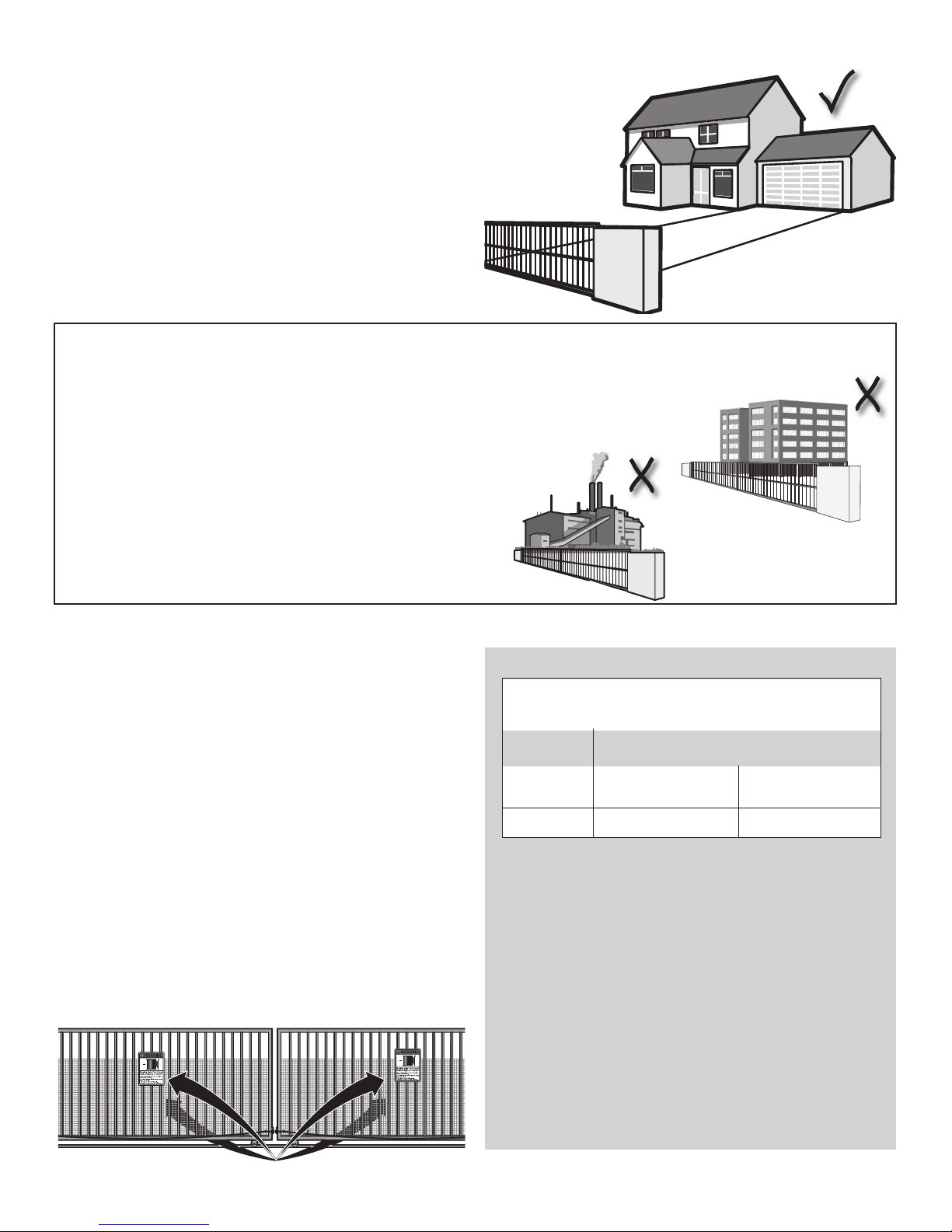
* MGL400-24 is designed for Residential use only. If you are unsure which
classification matches your site, call our customer service to clarify. Commercial &
Industrial installations will void your warranty.
RESIDENTIAL – VEHICULAR GATE OPERATOR
A vehicular gate operator (or system) intended for use in a home of one to four single
family dwellings, or a garage or parking area associated therewith.
NOT SUITABLE FOR:
COMMERCIAL – GENERAL ACCESS VEHICULAR GATE
OPERATOR
A vehicular gate operator (or system) intended for use in a commercial location or
building such as a multi-family housing unit (five or more single family units) hotel,
garage, retail store or other building servicing the general public.
INDUSTRIAL – GENERAL ACCESS VEHICULAR GATE
OPERATOR
A vehicular gate operator (or system) intended for use in a industrial location or
building such as a factory or loading dock area or other locations not intended to
service the general public.
RESIDENTIAL
COMMERCIAL
INDUSTRIAL
SAFETY ACCESSORY SELECTION
Merlin gate operators will accept external entrapment protection devices to protect
people from motorized gate systems. Below are the types of entrapment protection
systems for use on this operator.
ENTRAPMENT PROTECTION TYPES
Type A: Inherent obstruction sensing system, self-contained within the operator.
This system must sense and initiate the reverse of the gate within two
seconds of contact with a solid object (included).
Type B: Connections provided for a non-contact device, such as a photoelectric
eye can be used as a secondary protection (included).
Type C: Connections provided for a contact sensor. A contact device such as a
gate edge can be used for secondary protection (optional).
NOTE:
We recommend warning signs are placed in plain view on both sides of
the gate to warn pedestrians of the dangers of motorized gate systems.
ENTRAPMENT PROTECTION REQUIREMENTS
GATE OPERATOR ENTRAPMENT PROTECTION
Installation
CLASS
RESIDENTIAL
Swing Gate (Arm) Operator
Primary Type
A
Secondary Type
(recommended)
B or C
The chart above illustrates the entrapment protection requirements for
each of the three classes.
In order to complete a proper installation you must satisfy the entrapment
protection chart shown above. That means that the installation must have
one primary means of entrapment protection. A secondary means of
entrapment protection is highly recommended. Both
primary and secondary entrapment protection methods must be designed,
arranged or configured to protect against entrapments in both the open
and close directions of gate travel.
For Example:
For a slide gate system that is installed on a singlefamily residence you must provide the following: As your primary type of
entrapment protection you must provide Type A inherent (built into the
operator) entrapment sensing and we highly recommend at least one of
the following as your secondary entrapment protection: Non-contact
sensors such as photoelectric eyes (type B), Contact sensors such as gate
edges (type C).
2
SAFETY » SAFETY INSTALLATION INFORMATION
1. Vehicular gate systems provide convenience and security. Gate systems are
comprised of many component parts. The gate operator is only one
component. Each gate system is specifically designed for an individual
application.
2. Gate operating system designers, installers and users must take into account
the possible hazards associated with each individual application. Improperly
designed, installed or maintained systems can create risks for the user as well
as the bystander. Gate systems design and installation must reduce public
exposure to potential hazards.
3. A gate operator can create high levels of force in its function as a component
part of a gate system. Therefore, safety features must be incorporated into
every design. Specific safety features include:
• Gate Edges • Guards for Exposed Rollers • Photoelectric Sensors
• Vertical Posts • Instructional and Precautionary Signage
4. Install the gate operator only when:
a. The operator is appropriate for the construction and the usage class of the
gate.
b. All exposed pinch points are eliminated or guarded, and guarding is
supplied for exposed rollers.
5. The operator is intended for installation only on gates used for vehicles.
Pedestrians must be supplied with a separate access opening. The pedestrian
access opening shall be designed to promote pedestrian usage. Locate the
gate such that persons will not come in contact with the vehicular gate during
the entire path of travel of the vehicular gate.
6. The gate must be installed in a location so that enough clearance is supplied
between the gate and adjacent structures when opening and closing to reduce
the risk of entrapment. Swinging gates shall not open into public access areas.
7. The gate must be properly installed and work freely in both directions prior to
the installation of the gate operator.
8. Controls intended for user activation must be located at least 6 feet (1.83 m)
away from any moving part of the gate and where the user is prevented from
reaching over, under, around or through the gate to operate the controls.
Outdoor or easily accessible controls shall have a security feature to prevent
unauthorized use.
9. The Stop and/or Reset (if provided separately) must be located in the line-
of-sight of the gate. Activation of the reset control shall not cause the
operator to start.
10. WARNING SIGNS are included and should be installed, one on each side of
the gate where easily visible.
11. For a gate operator utilizing a non-contact sensor:
a. Reference owner’s manual regarding placement of non-contact sensor for
each type of application.
b. Care shall be exercised to reduce the risk of nuisance tripping, such as
when a vehicle trips the sensor while the gate is still moving.
c. One or more non-contact sensors shall be located where the risk of
entrapment or obstruction exists, such as the perimeter reachable by a
moving gate or barrier.
12. For a gate operator utilizing a contact sensor such as an edge sensor:
a. One or more contact sensors shall be located where the risk of entrapment
or obstruction exists, such as at the leading edge, trailing edge and post
mounted both inside and outside of a vehicular horizontal slide gate.
b. One or more contact sensors shall be located at the bottom edge of a
vehicular vertical lift gate.
c. A hard wired contact sensor shall be located and its wiring arranged so the
communication between the sensor and the gate operator is not subject to
mechanical damage.
d. A wireless contact sensor such as the one that transmits radio frequency
(RF) signals to the gate operator for entrapment protection functions shall
be located where the transmission of the signals are not obstructed or
impeded by building structures, natural landscaping or similar obstruction.
A wireless contact sensor shall function under the intended end-use
conditions.
e. One or more contact sensors shall be located on the inside and outside
leading edge of a swing gate. Additionally, if the bottom edge of a swing
gate is greater than 6 inches (152 mm) above the ground at any point in
its arc of travel, one or more contact sensors shall be located on the
bottom edge.
f. One or more contact sensors shall be located at the bottom edge of a
vertical barrier (arm).
3
SAFETY » GATE CONSTRUCTION INFORMATION
Vehicular gates should be installed in accordance with local standards.
1. GENERAL REQUIREMENTS
1.1 Gates shall be constructed in accordance with the provisions given for the
appropriate gate type listed.
1.2 Gates shall be designed, constructed and installed to not fall over more than
45 degrees from the vertical plane, when a gate is detached from the
supporting hardware.
1.3 Gates shall have smooth bottom edges, with vertical bottom edged
protrusions not exceeding 12.7 mm when other than the exceptions listed in
ASTM F2200.
1.4 The minimum height for barbed tape shall not be less than 2.44 m above
grade and for barbed wire shall not be less than 1.83 m above grade.
1.5 An existing gate latch shall be disabled when a manually operated gate is
retrofitted with a powered gate operator.
1.6 A gate latch shall not be installed on an automatically operated gate.
1.7 Protrusions shall not be permitted on any gate, refer to ASTM F2200 for
Exceptions.
1.8 Gates shall be designed, constructed and installed such that their movement
shall not be initiated by gravity when an automatic operator is disconnected.
1.9 A pedestrian gate shall not be incorporated into a vehicular gate panel or
that portion of the adjacent fence that the gate covers in the open position.
3.1.3 A gap, measured in the horizontal plane parallel to the roadway, between a
fixed stationary object nearest the roadway, (such as a gate support post)
and the gate frame when the gate is in either the fully open position or the
fully closed position, shall not exceed 57 mm, refer to ASTM F2200 for
Exception.
3.1.4 Positive stops shall be required to limit travel to the designed fully open and
fully closed positions. These stops shall be installed at either the top of the
gate, or at the bottom of the gate where such stops shall horizontally or
vertically project no more than is required to perform their intended
function.
3.1.5 All gates shall be designed with sufficient lateral stability to assure that the
gate will enter a receiver guide, refer to ASTM F2200 for panel types.
3.2 The following provisions shall apply to Class IV vehicular horizontal slide
gates:
3.2.1 All weight bearing exposed rollers 2.44 m, or less, above ground shall be
guarded or covered.
3.2.2 Positive stops shall be required to limit travel to the designed fully open and
fully closed positions. These stops shall be installed at either the top of the
gate, or at the bottom of the gate where such stops shall horizontally or
vertically project no more than is required to perform their intended
function.
2. SPECIFIC APPLICATIONS
2.1 Any non-automated gate that is to be automated shall be upgraded to
conform to the provisions of this specification.
2.2 This specification shall not apply to gates generally used for pedestrian
access and to vehicular gates not to be automated.
2.3 Any existing automated gate, when the operator requires replacement,
shall be upgraded to conform to the provisions of this specification in effect
at that time.
3. VEHICULAR HORIZONTAL SLIDE GATES
3.1 The following provisions shall apply to Residential I, Commercial I and
Commercial II vehicular horizontal slide gates:
3.1.1 All weight bearing exposed rollers 2.44 m, or less, above grade shall be
guarded or covered.
3.1.2 All openings located between 1.22 m and 1.83 m above grade shall be
designed, guarded or screened to prevent a
102 mm diameter sphere from passing through the openings anywhere in
the gate, and in that portion of the adjacent fence that covers in the open
position.
4. VEHICULAR HORIZONTAL SWING GATES
4.1 The following provisions shall apply to Residential I, Commercial I and
Commercial II vehicular horizontal swing gates:
4.1.1 Gates shall be designed, constructed and installed so as not to create an
entrapment area between the gate and the supporting structure or other
fixed object when the gate moves toward the fully open position, subject to
the provisions in the 4.1.1.1 and 4.1.1.2.
4.1.1.1 The width of an object (such as a wall, pillar or column) covered by a swing
gate when in the open position shall not exceed 102 mm, measured from
the centerline of the pivot point of the gate, refer to ASTM F2200 for
exception.
4.1.1.2 Except for the zone specified in Section 4.1.1.1, the distance between a
fixed object such as a wall, pillar or column, and a swing gate when in the
open position shall not be less than 406 mm, refer to ASTM F2200 for
exception.
4.2 Class IV vehicular horizontal swing gates shall be designed, constructed and
installed in accordance with security related parameters specific to the
application in question.
4
SAFETY » IMPORTANT SAFETY INFORMATION
• To prevent Serious Injury or Death from a moving gate - FOLLOW ALL
INSTRUCTIONS
INSTALLATION
To prevent SERIOUS INJURY or DEATH; one or more non-contact sensors shall be
located where the risk of entrapment or obstruction exists.
To prevent SERIOUS INJURY or DEATH from a moving gate:
• Entrapment protection devices MUST be installed to protect anyone who may
come near a moving gate.
• Locate entrapment protection devices to protect in BOTH the open and close
gate cycles.
• Locate entrapment protection devices to protect between moving gate and
RIGID objects, such as posts.
• A swinging gate shall NOT open into public access ways.
WIRING
• Check that the temperature range of -20oC to +50oC is suitable for the
location.
To prevent SERIOUS INJURY or DEATH from a moving gate:
• Install warning signs on the front and back of the gate in PLAIN VIEW.
• Permanently secure each warning sign in a suitable manner using fastening
holes.
ALWAYS wear protective gloves and eye protection when changing the battery or
working around the battery compartment.
• DO NOT use flooded lead acid battery.
• Flooded lead acid batteries will produce gases when discharging and
recharging which can explode.
• DO NOT dispose of battery in fire. Battery may explode. Check with local
codes for disposal instructions.
To reduce the risk of SEVERE INJURY or DEATH:
• ANY maintenance to the operator or in the area near the operator MUST NOT
be performed until disconnecting the electrical power and locking-out the
power via the operator power switch. Upon completion of maintenance the
area MUST be cleared and secured, at that time the unit may be returned to
service.
• Disconnect power at the fuse box BEFORE proceeding. Operator MUST be
properly grounded and connected in accordance with local electrical codes.
NOTE: The operator should be on a separate fused line of adequate capacity.
• ALL electrical connections MUST be made by a qualified individual.
To AVOID damaging plug-in transformer, it MUST be enclosed in a suitable
weatherproof enclosure and provided with proper weatherproof fixtures.
To AVOID damaging gas, power or other underground utility lines, contact
underground utility locating companies BEFORE digging.
ADJUSTMENT
Without a properly installed safety reversal system, persons (particularly small
children) could be SERIOUSLY INJURED or KILLED by a closing gate.
• Too much force on gate will interfere with proper operation of safety reversal
system.
• NEVER increase force beyond minimum amount required to close gate.
• NEVER use force adjustments to compensate for a binding or sticking gate.
• DO NOT install ANY wiring or attempt to run the operator without consulting
the wiring diagram. We recommend that you install an optional reversing
edge BEFORE proceeding with the control station installation.
• ALL power wiring should be on a dedicated circuit and well protected. The
location of the power disconnect should be visible and clearly labeled.
• ALL power and control wiring MUST be run in separate conduit.
• BEFORE installing power wiring or control stations be sure to follow ALL
specifications and warnings described below. Failure to do so may result in
SEVERE INJURY to persons and/or damage to operator.
To reduce the risk of FIRE or INJURY to persons use only Merlin replacement
batteries.
• If one control (force or travel limits) is adjusted, the other control may also
need adjustment.
• After ANY adjustments are made, the safety reversal system MUST be tested.
Gate MUST reverse on contact with a rigid object.
5
SAFETY » IMPORTANT SAFETY INFORMATION
OPERATION AND MAINTENANCE
• READ AND FOLLOW ALL INSTRUCTIONS.
• NEVER let children operate or play with gate controls. Keep the remote control
away from children.
• ALWAYS keep people and objects away from the gate. NO ONE SHOULD
CROSS THE PATH OF THE MOVING GATE.
• Test the gate operator monthly. The gate MUST reverse on contact with a rigid
object or stop when an object activates the non-contact sensors. After
adjusting the force or the limit of travel, retest the gate operator. Failure to
adjust and retest the gate operator properly can increase the risk of INJURY
or DEATH.
To reduce the risk of FIRE or INJURY to persons use only Merlin replacement
batteries.
TROUBLESHOOTING
To protect against fire and electrocution:
• Disconnect power and battery BEFORE installing or servicing operator.
• Use the emergency release ONLY when the gate is not moving.
• KEEP GATES PROPERLY MAINTAINED. Read the owner’s manual. Have a
qualified service person make repairs to gate hardware.
• The entrance is for vehicles ONLY. Pedestrians MUST use separate entrance.
• Disconnect ALL power before performing ANY maintenance.
• ALL maintenance MUST be performed by a Merlin professional.
• SAVE THESE INSTRUCTIONS.
To avoid SERIOUS personal INJURY or DEATH from electrocution, DISCONNECT
electrical power to operator BEFORE proceeding.
For continued protection against fire:
• Replace ONLY with fuse of same type and rating.
6
INTRODUCTION » OPERATOR SPECIFICATIONS + CARTON INVENTORY
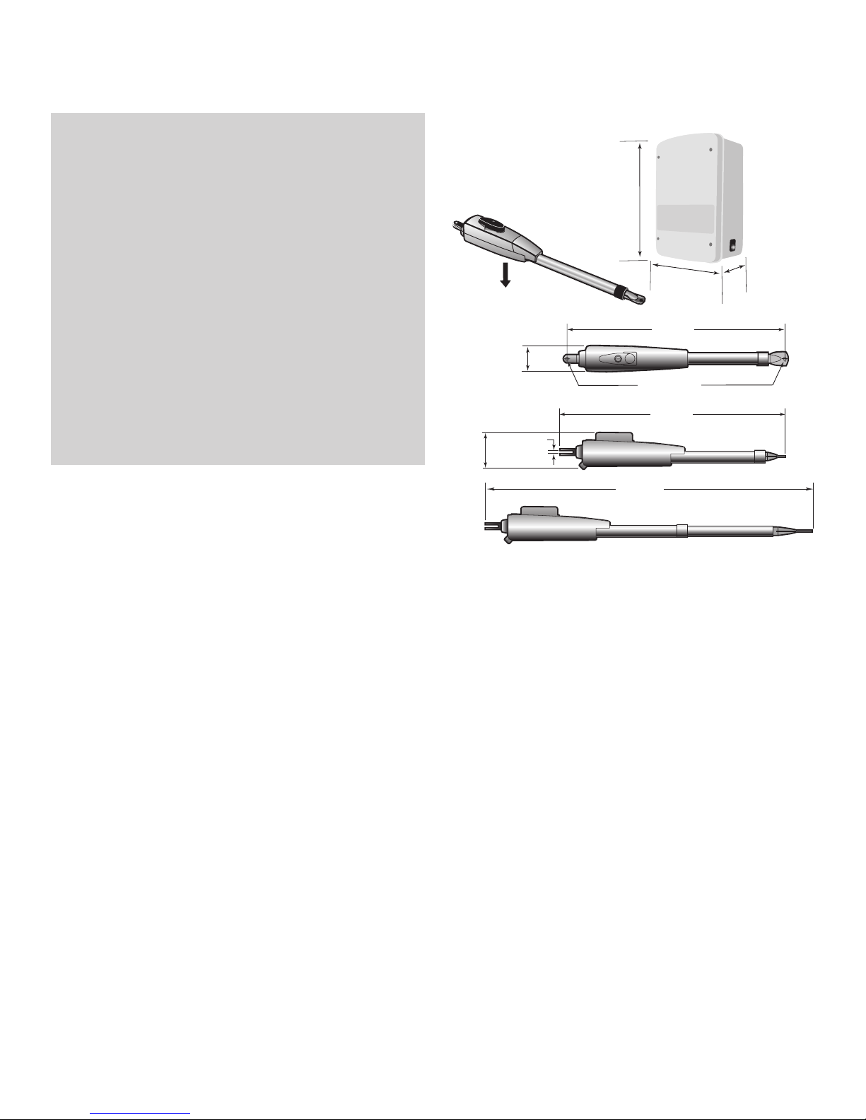
OPERATOR SPECIFICATIONS
Operating Cycles: 100 per day
Main Supply (Motor): 24 Vdc
Current Consumption: 2A
Power Consumption: 48 Watts
Battery Charger Supply: 26 Vac, 29VA or 36 Vdc, 40VA
Maximum Gate Width: 4.9 m
Maximum Gate Weight: 249.5 kg
Protection Class: NEMA 3R
Travel Speed: 14-18 seconds for a 90° opening
Rated Operating Time: 4 Minutes
Temperature: -20° C to + 50° C
Main Supply (Control)
Dedicated Circuit: 240 V~/50 Hz
Absorbed Power: 0.75 Watts
Protection Fuse Battery: ATC 20A
Weight: 13.2 lbs. (6 kg.)
(10.2 cm)
4.5"
(11.2 cm)
4"
.25"
(0.635 cm)
14"
(35.6 cm)
10"
(25.4 cm)
36.3"
(92.1 cm)
.475" DIA.
(1.2 cm DIA.)
37.4"
(95 cm)
RESET
6"
(15.2 cm)
53.5"
(136 cm)
CARTON INVENTORY
Carton inventory is based on a Single Operator. For Primary (Gate 1) and Secondary (Gate 2) installation the carton inventory is doubled except for control box.
• Standard Control Box - 433 MHz (1)
• Antenna (1)
• Transmitters (2)
• Hardware Bag (1)
• Gate Operator Arm
• Motor Cable - Six Conductor, 9 feet (2.7 m)
• Warning Sign (2)
• Battery (2)
• Transformer (1)
MGL400-24S (SECOND GATE OPERATOR ARM)
• Motor Cable - Six Conductor, 40 feet (12.2 m)
• Junction Box - IP56 (1)
• Phillips Head Mounting Screws (4)
• Anchors (4)
• Terminal Block - Twelve Connectors (1)
HARDWARE INVENTORY
• Post Bracket (1)
• Pull-to-Open Bracket (1)
• Hex Bolt 5/16"-18 X 1-1/2" (5)
• Square Neck Carriage Bolt 3/8"-16 X 6" (2)
• Hex Nut 3/8"-16 (2)
• Hex Nut 5/16"-18 (5)
• Flat Washer 5/16" (5)
• Flat Washer 3/8" (5)
• Lock Washer 5/16" (5)
• Lock Washer 3/8" (5)
• Gate Mounting Bracket (1)
• Hairpin Clip (2)
• Pin (2)
• Hex Bolt 3/8"-16 X 1-1/2" (1)
• Bolt 2-3/4" (2)
• Keylock Cap (1)
• Keys (2)
7
INTRODUCTION » ADDITIONAL ITEMS NEEDED FOR INSTALLATION + TOOLS NEEDED
l
ADDITIONAL ITEMS NEEDED FOR INSTALLATION
PERMANENT FASTENERS FOR WARNING SIGN
EARTH GROUND ROD (OPTIONAL)
POWER SUPPLY:
* Mains powered - If the opener is to be mains-powered, then the 3-pin power plug should be shielded from the effects of weather. If the plug is cut off for hard-
wiring, then the safety of the unit becomes the responsibility of the installing electrician. An isolating switch is recommended, but all mains wiring should be in
accordance with regulations.
* Solar Powered Panels - The size of these depends on: the duty cycle of the gates; the hours of sunlight; and the number and type of accessories fitted. 30
watts is recommended for Residential use.
* Battery Powered with trickle charging - Due to the high cost of long runs of heavy cable, it may be more economic in some installations to operate
the gates from a battery, which is charged from a remotely located trickle charger.
For example: a 26 VAC 1.1 Amp plug pack can be located at the house, with appropriate wiring to the gate, controller, and battery some distance away. Follow the tables
for minimum recommended conductor sizes for different distances.
Cable length Conductor size mm
Up to 30 m 1.5 mm
Up to 100 m 2.5 mm
2
2
2
AWG#
16
14
WIRING: All wiring must be arranged to prevent water entering the controller enclosure. Do not wire mains voltage and low voltage control wires in the same
conduit.
* Low voltage cable sizes - Voltage will drop along low voltage cables over long distances. It is recommended to use cable with conductors of the following
minimum cross sectional areas. The table lists lengths for twin-core cable, from a 24 V supply and 5 Amp load.
Cable length Conductor size mm
3 m 1 mm
5 m 1.5 mm
10 m 2.5 mm
15 m 4 mm
20 m 6 mm
25 m 6 mm
30 m 10 mm
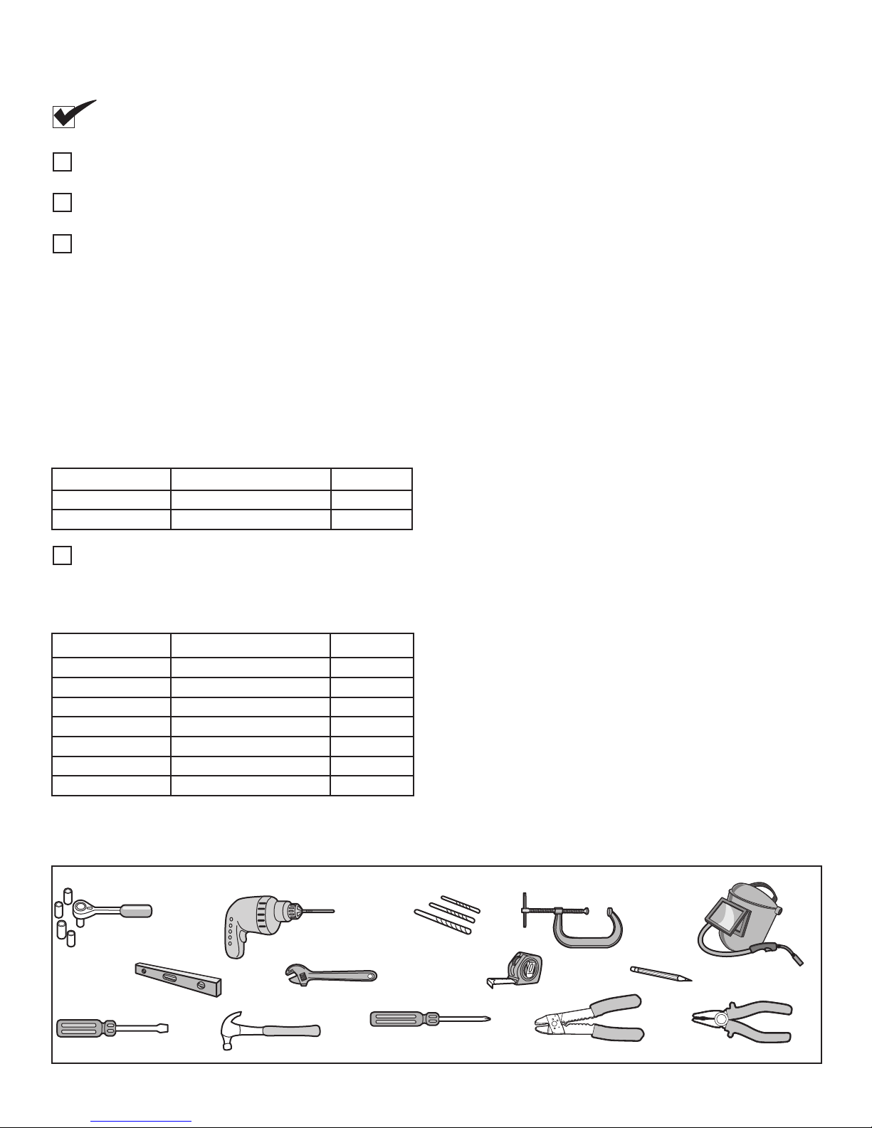
TOOLS NEEDED
2
2
2
2
2
2
2
2
AWG#
16
16
14
12
10
10
8
During assembly, installation and adjustment of the operator, instructions will call for tools as illustrated below.
Deep Well Sockets
and Wrench
1/2", 5/8", 7/16", 9/16"
and 1/4"
Carpenter's Level
Drill
Adjustable End Wrench
Drill Bits
1/2", 3/16", 5/16"
and 5/32"
2
1
Tape Measure
Clamps
Welder (Optional)
Pencil
Screwdriver
Hammer
Phillips Head Screwdriver
8
Wire Strippers (Optional)
Wire Cutters (Optiona
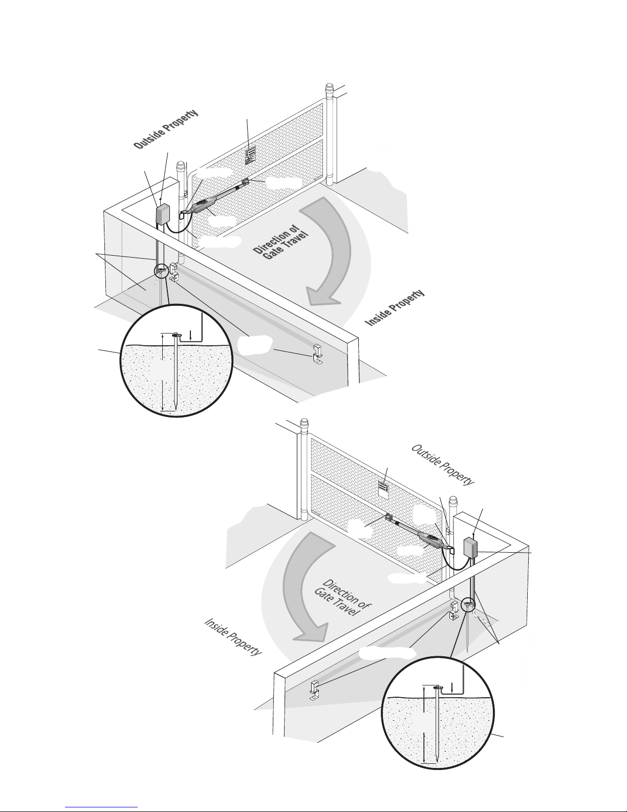
INSTALLATION » OVERVIEW OF TYPICAL INSTALLATION
Moving Gate Can Cause
Injury or Death
KEEP CLEAR! Gate may move at any
time without prior warnin
g.
Do not let children operate the gate or
play in the gate area.
This entrance is for vehicles only
Pedestrians must use separate entrance
12
gauge
wire
8 ft.
(2.4 m)
12
gauge
wire
8 ft.
(2.4 m)
LEFT-HAND GATE
Warning Sign
Antenna
Control Box with Batteries
PVC Conduit (not
provided) to protect the
low voltage wire from
lawn mowers and string
trimmers.
Hinge
Post Bracket
Gate Bracket
Operator
Operator Cable
Earth Ground Installation
(Optional)
RIGHT-HAND GATE
Photoelectric
Sensors
NOTE:
One or more non-contact sensors
shall be located where the risk of
entrapment or obstruction exists at either
the opening or closing direction. Care
shall be exercised to reduce the risk of
nuisance tripping, such as when a
vehicle trips the sensor while the gate is
still moving.
Warning Sign
Hinge
Post
Gate
Bracket
Bracket
Operator
Operator Cable
Antenna
Control Box with
Batteries
Photoelectric Sensors
PVC Conduit (not provided) to protect the
low voltage wire from lawn mowers and
string trimmers.
Earth Ground
Installation (Optional)
9
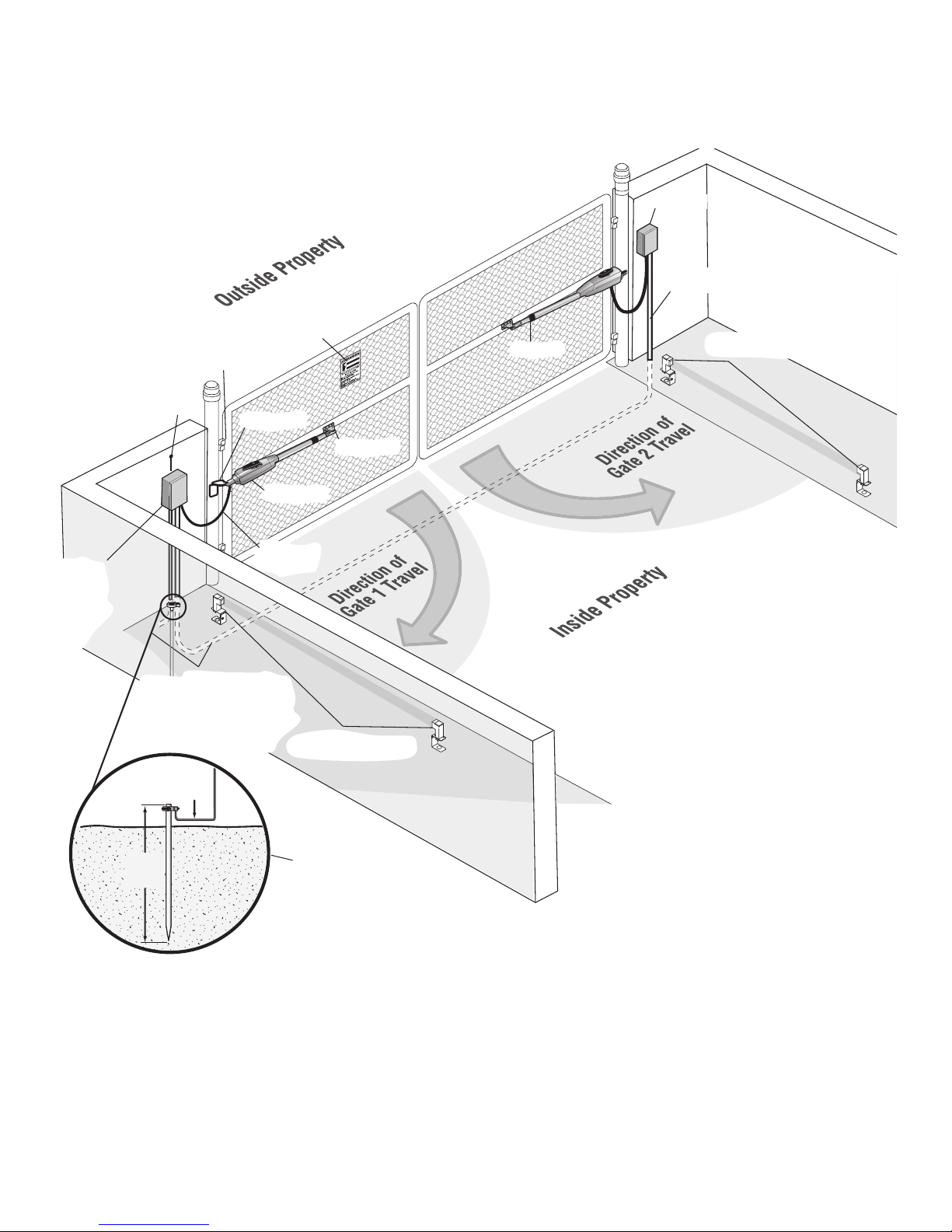
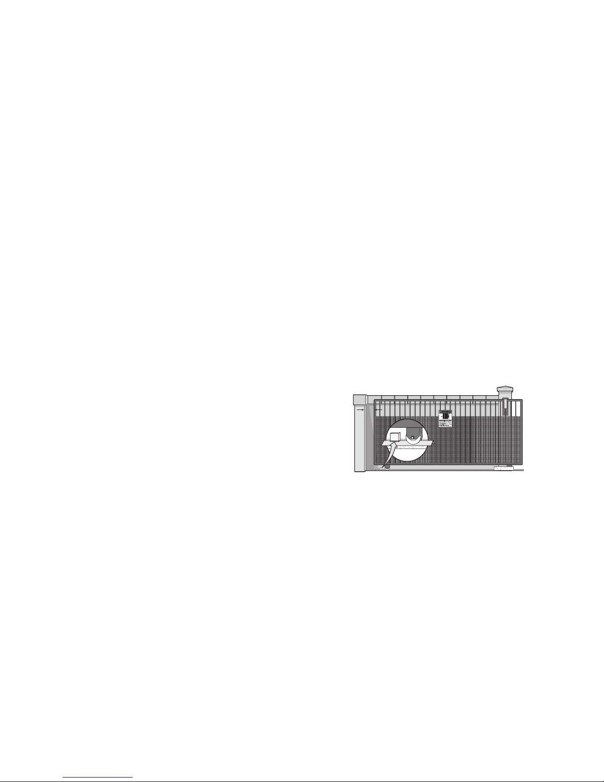
INSTALLATION » OVERVIEW OF TYPICAL INSTALLATION
DUAL GATE
Junction Box
Extension Cable
Control Box
with Batteries
Hinge
Antenna
Post Bracket
Operator Cable
PVC Conduit (not provided) to protect
the low voltage wire from lawn
mowers and string trimmers.
12
gauge
wire
Warning Sign
Gate 1
Gate Bracket
Photoelectric Sensors
Gate 2
Photoelectric Sensors
8 ft.
(2.4 m)
Earth Ground
Installation (Optional)
10
NOTE:
One or more non-contact
sensors shall be located where the risk
of entrapment or obstruction exists at
either the opening or closing direction.
Care shall be exercised to reduce the
risk of nuisance tripping, such as when a
vehicle trips the sensor while the gate is
still moving.
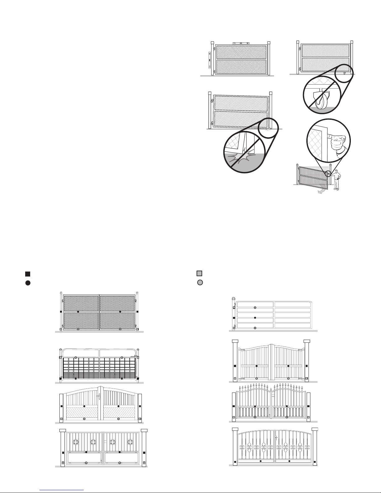
INSTALLATION » CHECK YOUR GATE + MOUNTING OPTIONS
CHECK YOUR GATE
A
Gate MUST be level. Gate and gate post MUST be plumb.
A
Remove ANY/ALL wheels from the bottom of gate.
B
Gate MUST NOT hit or drag across ground.
C
Gate MUST swing freely and be supported entirely by its hinges.
D
C
B
D
MOUNTING OPTIONS
Mounting locations vary depending on type and style of your gate. Minimum
distance from the ground should not be less than 10.2 cm from the bottom of the
gate operator arm.
RECOMMENDED:
= Gate post bracket mounting locations
= Gate bracket mount locations
OPTIONAL:
= Gate post bracket mounting locations
= Gate bracket mount locations
11
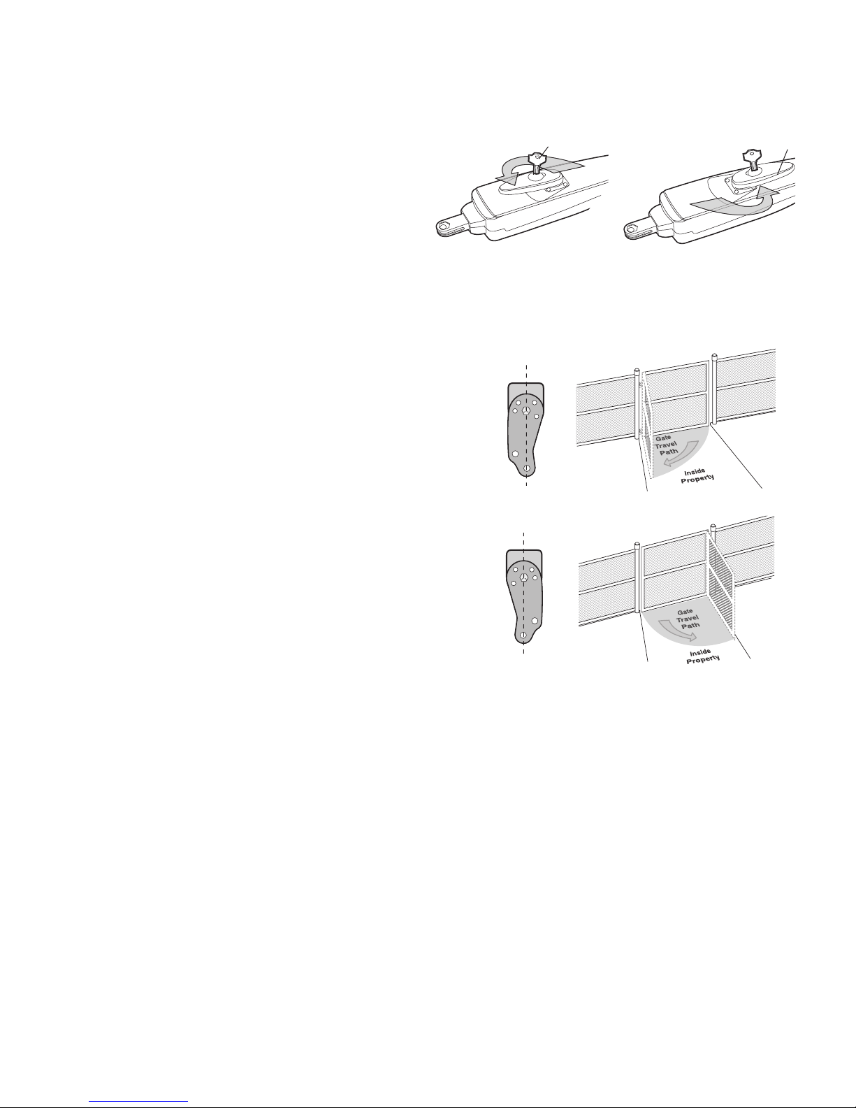
INSTALLATION » MANUAL RELEASE + DETERMINE POSITION OF THE PULL-TO-OPEN BRACKET
MANUAL RELEASE
Insert the key into the lock and turn it 180° counterclockwise.
1
Turn the release lever 180° counterclockwise.
2
The operator is now in manual mode.
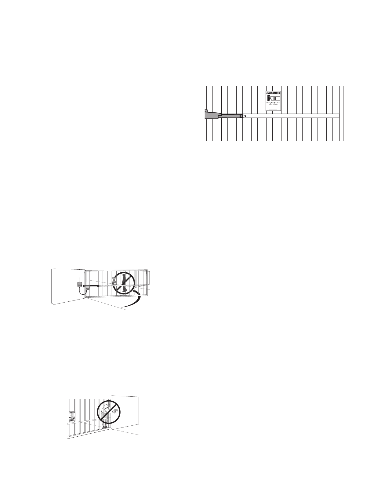
DETERMINE POSITION OF THE PULL-TO-OPEN BRACKET
The Pull-to-Open bracket can be assembled to work on a Left-Hand or a
Right-Hand gate.
Review the gate types and select the type of installation you will require.
1
NOTE:
damage the operator.
If the Pull-to-Open bracket is not assembled correctly you will
1
1
LEFT-HAND GATE
RIGHT-HAND GATE
Key
Release Lever
2
12
INSTALLATION » ASSEMBLE GATE POST BRACKET (PULL-TO-OPEN) + ATTACH BRACKETS TO GATE OPERATOR
All the illustrations on the following pages display a typical Left-Hand Gate
installation.
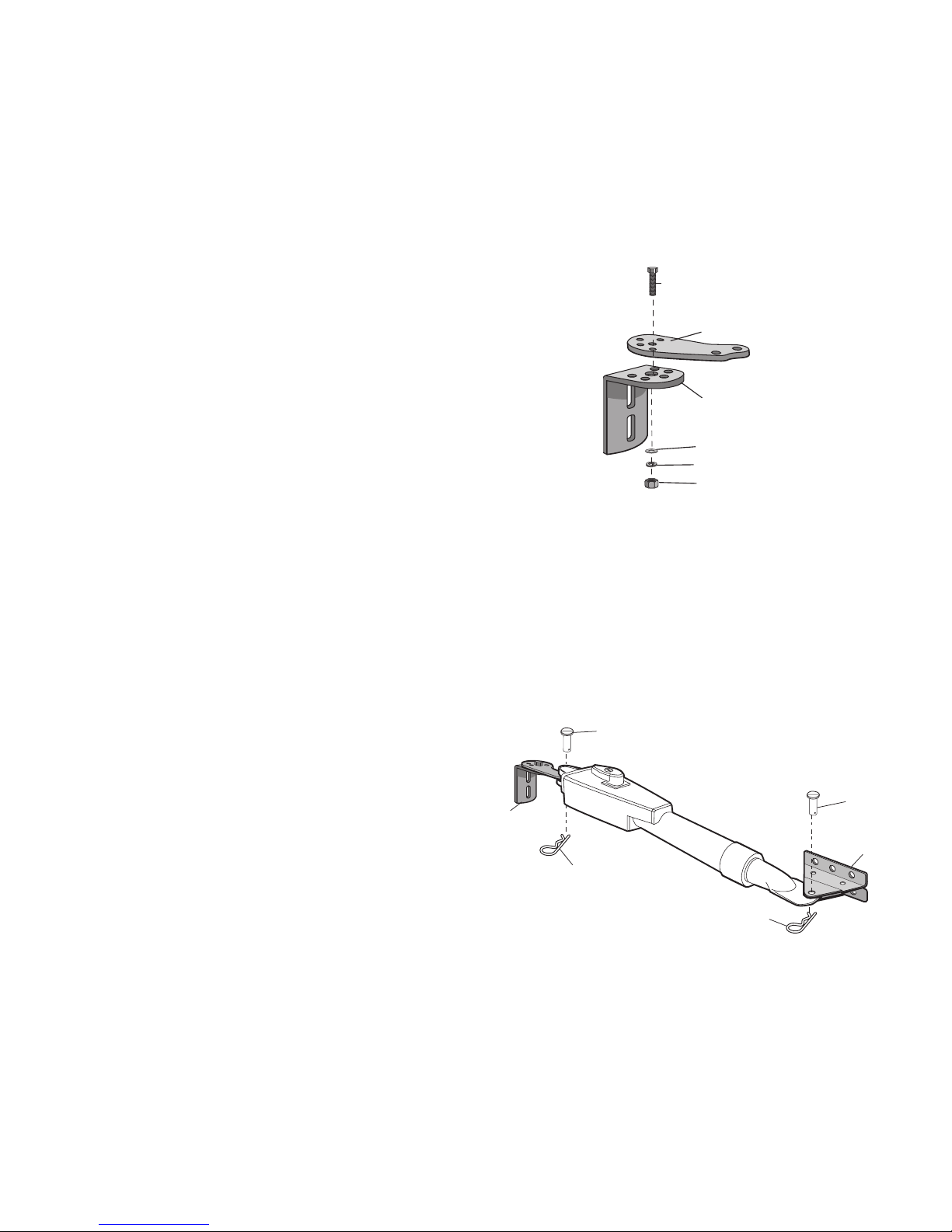
ASSEMBLE GATE POST BRACKET (PULL-TO-OPEN)
Assemble gate post bracket by placing Pull-to-Open bracket on top of post
1
bracket.
Insert the bolt through both brackets and secure with washer, lock washer
2
and nut.
ATTACH BRACKETS TO GATE OPERATOR
Attach post bracket assembly to operator using pins and hairpin clips.
1
1
1
Pin
2
Hex Bolt 3/8"
Pull-to-open
Bracket
Post Bracket
Washer
Lock Washer
Nut
Attach gate bracket to operator using pins and hairpin clips.
2
Post Bracket Assembly
13
Hairpin Clip
Hairpin Clip
2
Pin
Gate Bracket
 Loading...