

Page 1
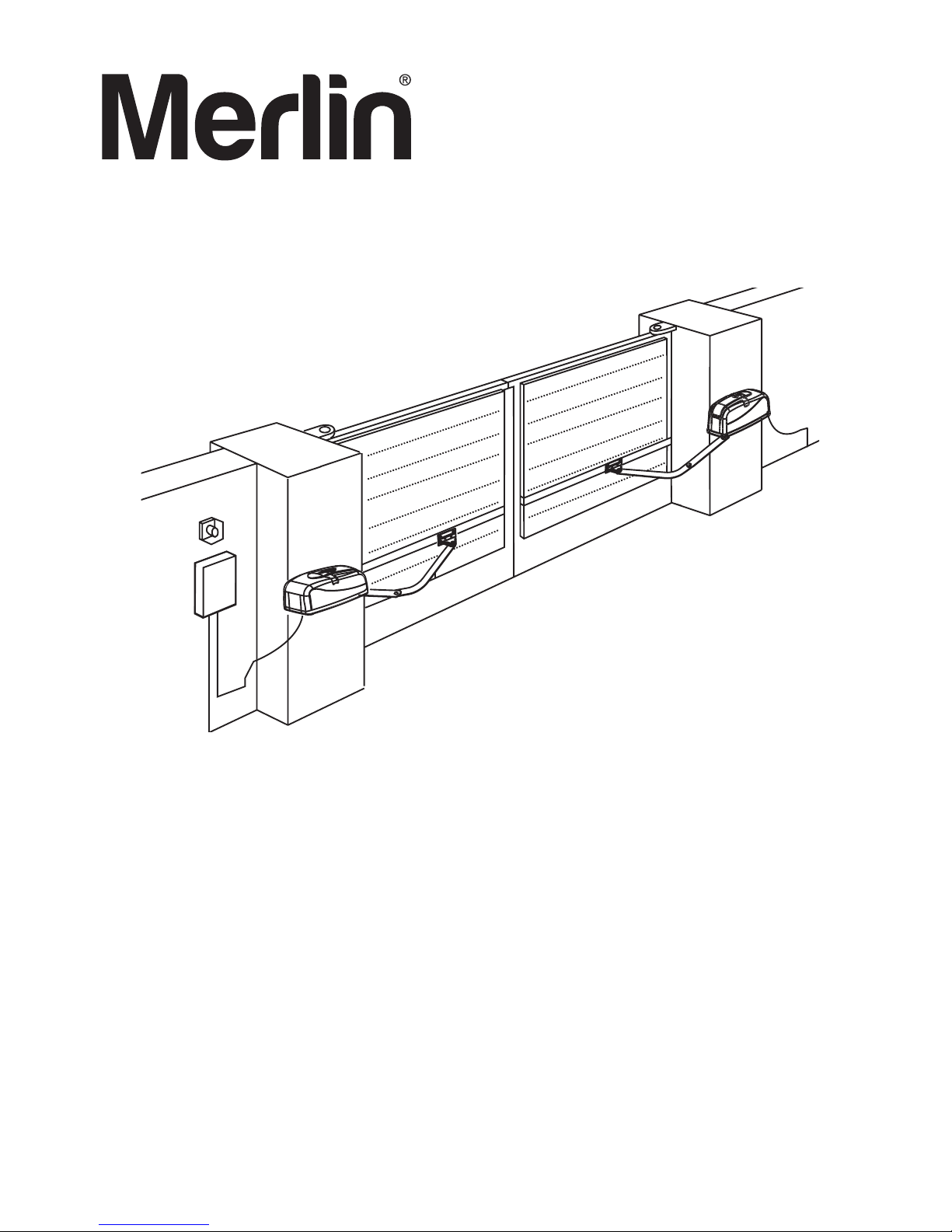
WingMate
3
Installation and operation instructions
for MGA600 ARTICULATED Gate Motor.
DESIGNED FOR PROFESSIONAL INSTALLATION
ONLY
Chamberlain Australia Pty Ltd
PO Box 1446
Lane Cove NSW 1595
Phone Toll Free 1800 638 234
Chamberlain New Zealand Ltd
PO Box 100-221
North Shore 0745
Phone Toll Free 0800 653 667
www.go-merlin.com
Articulated Swing Gate Opener
For gates up to 3 meters
Owners Copy: Please keep these instructions for future reference
Page 2

1
Do not wear rings, watches or loose clothing while
servicing or installing a gate opener.
Installation and wiring must be in compliance with
your local building and electrical installation codes.
Power cables must only be connected to a properly earthed supply.
Entrapment between the moving gate and walls
due to the opening movement must be avoided by
using safety edges or IR sensors when necessary.
Please remove any locks fitted to the gate in order to
prevent damage to the gate. A special E-Lock is
available as accessory.
After installation, ensure that the gate opener system is properly adjusted and that the safety system and the manual release function correctly.
This drive must not be used with a gate incorporating a wicket door.
The actuating member of a biased-off switch, if installed, is to be located within direct sight of the
gate but away from moving parts. Unless it is key
operated, it is to be installed at a minimum height of
1.5m and not accessible to the public.
It is important to make sure that the gate always
runs smoothly. Gates which stick or jam must be
repaired immediately. Employ a qualified technician to repair the gate, never attempt to repair it
yourself.
Keep additional accessories away from children.
Do not allow children to play with any controls.
Keep remote controls away from children. Operate gate when it is in full view and no one is near
the gate. A gate can cause serious injuries or
death as it opens or closes.
Connect the gate opener to a properly
EARTHED general purpose 240 V mains power
outlet installed by a qualified electrical contractor.
DISCONNECT THE POWER CORD from the
mains power before making any repairs or removing covers. Only EXPERIENCED service
personnel should remove covers from the gate
opener.
Make sure that people who install, maintain or
operate the gate drive follow these instructions.
Keep these instructions in a safe place so that
you can refer to them quickly when you need to.
The gate drive system is to be regularly examined for any signs of wear and tear or damage.
The gate drive system must not be used if repair
or adjustments are needed.
This safety alert symbol means "Caution" - failure to comply with such an instruction involves risk of personal injury or
damage to property. Please read these warnings carefully.
This gate drive mechanism is designed and tested to offer appropriately safe service provided it is installed and operated
in strict accordance with the following safety rules.
Incorrect installation and/or failure to comply with the following instructions may result in serious personal injury or
property damage.
PLEASE START BY READING THESE IMPORTANT SAFETY RULES
IMPORTANT ADVICE: THESE INSTRUCTIONS ESSENTIALLY DESCRIBE THE INSTALLATION OF THE MGA600 DRIVE WITH THE ACCESSORY ARM ART-3, FOR INSTALLATION ON A SWING GATE
IF THE ART-1 FOLDING GATE ARM OR THE SPACE-SAVING ART-2 GATE ARM ARE INSTALLED IT IS ESSENTIAL TO FOLLOW THE INSTRUCTIONS INCLUDED WITH THOSE ITEMS. THE INSTALLATION WORK VARIES FROM THESE INSTRUCTIONS AT SOME POINTS.
WARNING AND SAFETY ADVICE IS EXCEPTED FROM THIS.
BEFORE YOU BEGIN
The MGA is suitable for use with wide pillars, up to about 30cm in width. The maximum recommended opening angle
of the gate is 125 degrees. Ensure that ample space is available next to the drive for the arms and assembly. Gates
exposed to a high wind load must be fixed with an electric lock for additional protection. While the drive is fitted with
internal limit switches, stops should also be mounted on the ground to prevent gate rattle or flutter. There are many
factors to consider when choosing the right drive mechanism. Assuming that a gate functions properly, "startup" is the
most difficult phase, once the gate is in motion, significantly less force is usually required to move it.
• Gate size: The gate size for this drive must not be more than 3.0m. Wind can brake or distort the gate, thereby in-
creasing the amount of force needed to move it considerably.
• Gate weight: The weight of the gate must not be more than 250kg.
• Effect of temperature: Be sure that the ambient temperature where the drive is installed will be between -20 to
+55C
0
deg since low outdoor temperature can prevent the motor from starting. High outdoor temperatures along with
frequent use can cause the motor thermal protection to operate. Wait 15 minutes if this has occurred.
Page 3
2
WAR NINGS
W
arnings and Precautions . . . . . . . . . . . . . . . . . . . . . . . .1
C
arton Inventory . . . . . . . . . . . . . . . . . . . . . . . . . . . . . . . .2
GATE M OTOR INSTALLATION
Installation Checklist . . . . . . . . . . . . . . . . . . . . . . . . . . . . .3
Gate Types . . . . . . . . . . . . . . . . . . . . . . . . . . . . . . . . . . . .3
G
ate Motor Installation . . . . . . . . . . . . . . . . . . . . . . . . . .4-6
M
anual Release . . . . . . . . . . . . . . . . . . . . . . . . . . . . . . . .5
CO NTROL BOAR D INS TALLATION
Warnings . . . . . . . . . . . . . . . . . . . . . . . . . . . . . . . . . . . . . .6
Safety Installation Information . . . . . . . . . . . . . . . . . . . . . .7
Control Board Specifications . . . . . . . . . . . . . . . . . . . . . . .8
Cable Requirements . . . . . . . . . . . . . . . . . . . . . . . . . . . . .8
Mount The Control Box . . . . . . . . . . . . . . . . . . . . . . . .9-10
Wiring Single Motor To Control Board . . . . . . . . . . . .11-12
Wiring Dual Motors To Control Board . . . . . . . . . . . .13-14
Installation of Safety IR Beams . . . . . . . . . . . . . . . . . . . .15
B
AS IC CO NTROL BOAR D SETU P
BiPart Delay . . . . . . . . . . . . . . . . . . . . . . . . . . . . . . . . . .14
C
onnecting Control board to GPO . . . . . . . . . . . . . . . . .16
C
onnecting Batteries . . . . . . . . . . . . . . . . . . . . . . . . . . . .17
Setting the CAMS . . . . . . . . . . . . . . . . . . . . . . . . . . . . . .18
Programming . . . . . . . . . . . . . . . . . . . . . . . . . . . . . . .19-20
F
orce Setting/Timer to Close/Party mode . . . . . . . . . . .21
Program Remote Control Transmitters . . . . . . . . . . . . . .22
OP ERATI ON an d MAI N TENA N C E
Operation of your Gate Opener . . . . . . . . . . . . . . . . . . .23
Wiring Diagram . . . . . . . . . . . . . . . . . . . . . . . . . . . . . . . .24
Control Inputs . . . . . . . . . . . . . . . . . . . . . . . . . . . . . . . . .25
Diagnostics . . . . . . . . . . . . . . . . . . . . . . . . . . . . . . . . . . .26
Troubleshooting . . . . . . . . . . . . . . . . . . . . . . . . . . . . .27-29
Spares . . . . . . . . . . . . . . . . . . . . . . . . . . . . . . . . . . . . . . .30
Warranty . . . . . . . . . . . . . . . . . . . . . . . . . . . . . . . . . . . . .31
M
anual
1.
2.
3.
4.
5.
6.
7.
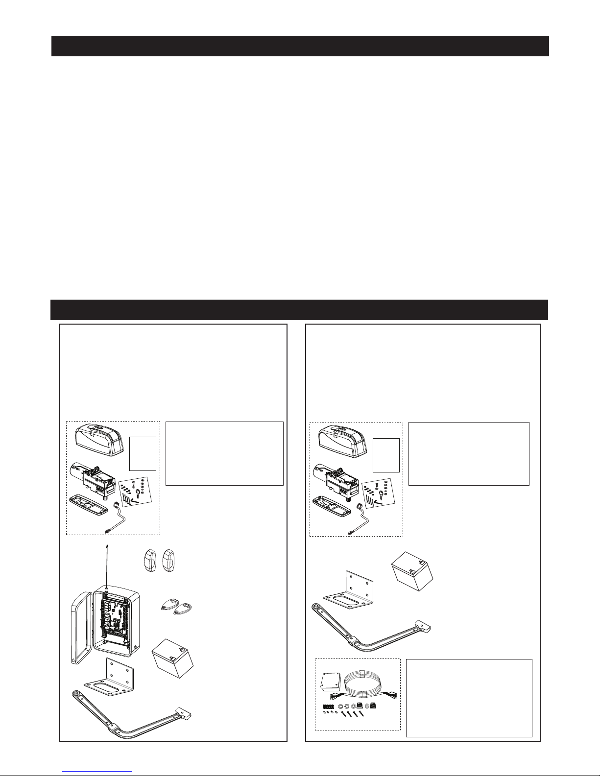
1. MGA Carton Contents:
• Motor x1
• Release key x1
• Hardwarebag x1
• Manual x1
MGA600M Carton Contents (Master Kit):
1. MGA x1
2. CB12ANZ (Control Board)
3. ART-3AL x1
4. ART-7 (041AART-0007) x1
5. Battery (MER150) to suit CB12ANZ x1
6. Transmitters C945 x2
7. 772ANZ IR Beams x1
Manual
1.
2.
3.
4.
5. JB12M
1. MGA Carton Contents:
• Motor x1
• Release key x1
• Hardwarebag x1
• Manual x1
5. JB12M CONTENTS:
• Junction Box x1
• Extension Cable - Six Conductor
(12.2m) x1
• Terminal Block - 12 Connectors x1
• Anchors x4
• Phillips Head Mounting Screws x4
• Strain Relief with Mounting Nut x2
MGA600S Carton Contents (Slave Kit):
1. MGA x1
2. ART-3AL x1
3. ART-7 (041AART-0007) x1
4. Battery (MER150) to suit CB12ANZ x1
5. JB12M (LA400-JB40 kit) x1
T A B L E O F C O N T E N T S
C A R T O N C O N T E N T S
Page 4
3
I
NSTALLATION CHECKLIST - PREPARATIONS
Check the carton contents and read the instructions carefully. Make sure your gate equipment operates perfectly. The
gate must run evenly and smoothly and must not stick at any point. Remember that the ground level may be several
centimeters higher in winter. The gate must be stable and as free of backlash as possible in order to prevent any unwanted
t
o and fro movement. The more smoothly the gate leaf runs, the more sensitive the force adjustment must be.
N
ote down any materials you still need and obtain them before starting to install. Heavy-duty plugs, bolts, gate stops,
cables, distribution boxes, tools, etc.
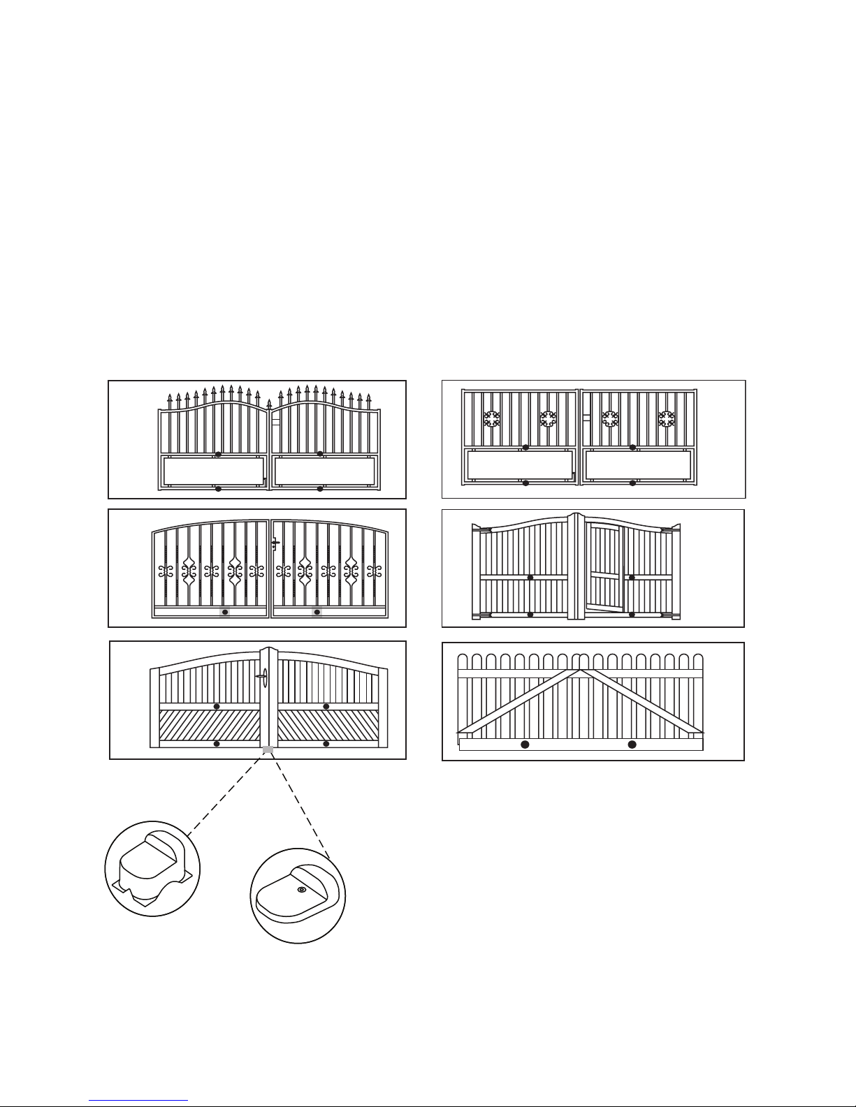
GATE TYPES
T
he gate type determines the location where the drive mechanism is installed. If the gate stop is on the ground, the drive
mechanism must also be installed at a height that is as low as possible so that it cannot twist the gate. Use only parts of
the gate frame for fixing purposes.
For steel gates, the gate fitting must be attached to the main frame. If you are uncertain whether the available support is
sufficiently stable, reinforce it.
In the case of wooden gates, the gate fitting must be through bolted. It is advisable to fit a plate from the outside so that
the fixing brackets cannot become loose over time. Thin wooden gates must also be reinforced in order to withstand the
stresses encountered.
FOR TWO GATE APPLICATION A FIXED GATE STOP MUST BE INSTALLED.
Gate stops save wear and tear on the drive mechanism, gate and fittings. Operating a
gate without fixed limit stops results in poor performance. It is often dangerous, leads
to premature wear in the case of heavy gates often exposed to wind stress.
Page 5
4
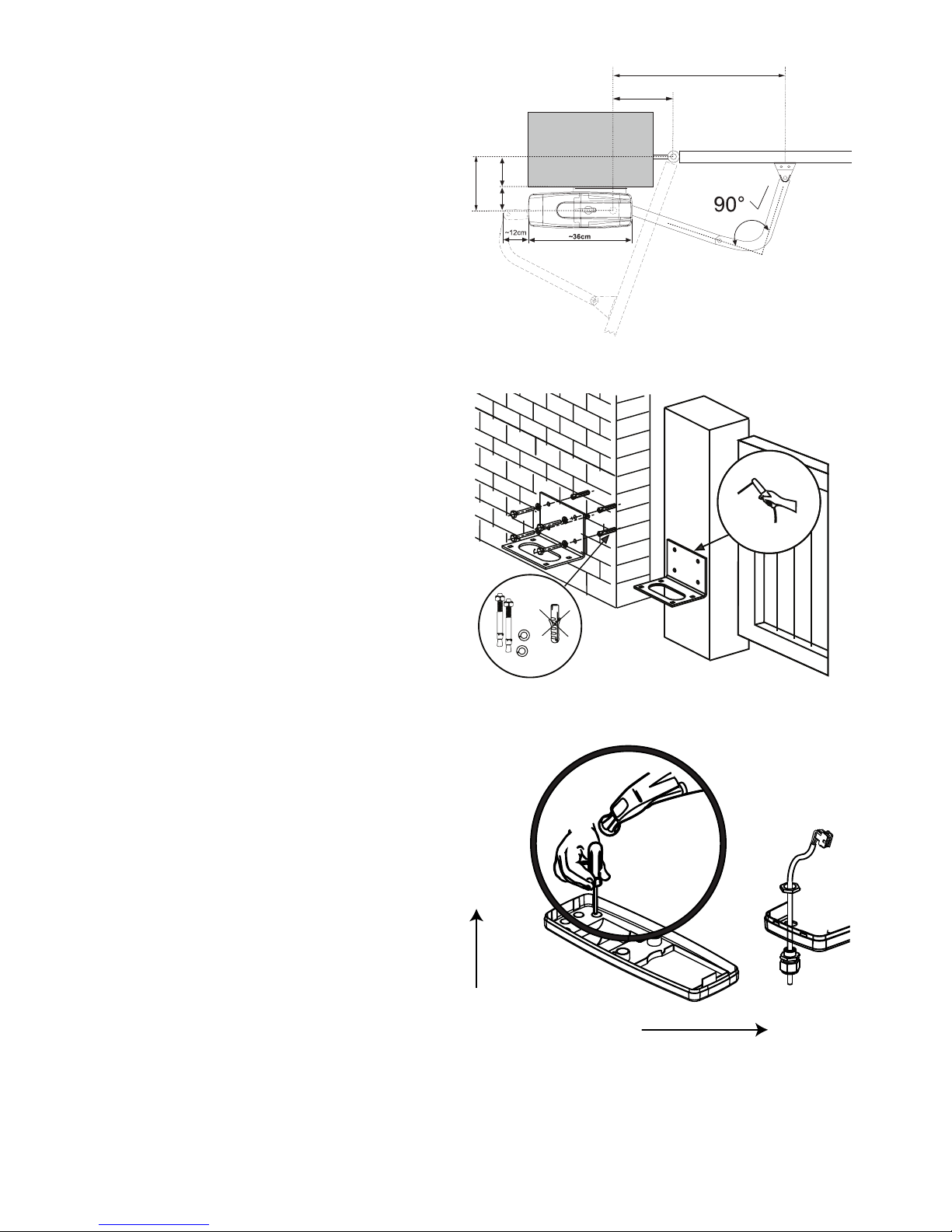
M
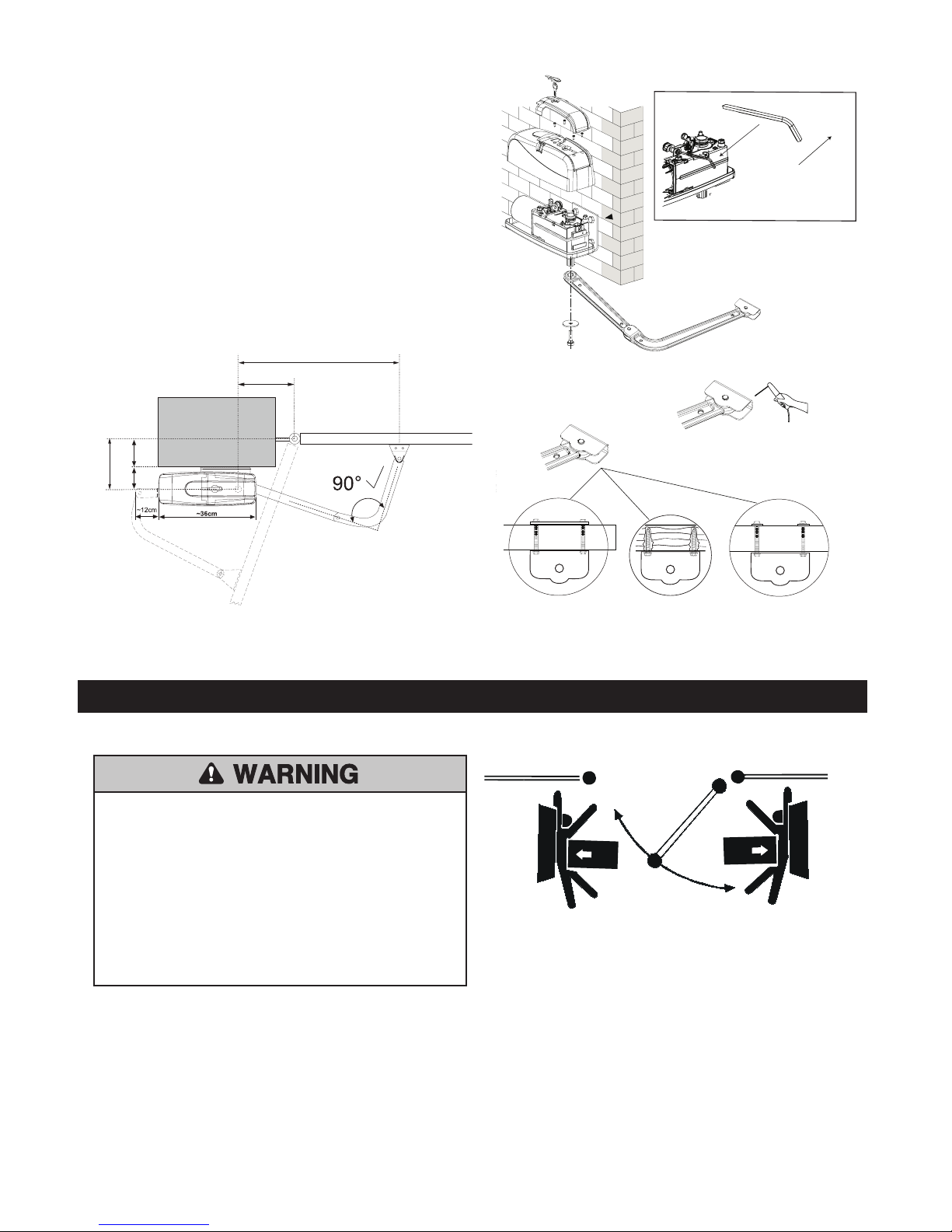
OUNTING REQUIREMENTS
The gate drive mechanism is suitable for use in conjunction
with pillars with a max. thickness of 30cm. The amount of
room around the pier affects the opening angle and the pos
ition of the arms. The drive mechanism is equipped with
built-in limit stops for both the OPEN and CLOSE directions. A different opening angle can be set for the left-hand
wing as compared with the right-hand one.
A=38,5cm
8,5cm
30cm
C
B=60-70cm
7-8 cm = 90°
max. 10 cm
=
INSTALLATION
Step 1 Install Motor Bracket
For Stone or reinforce concrete pillars use Dynabolts or
Chemical anchors (not supplied) to mount the motor support bracket onto the wall at the desired height. The gate
motor exerts a considerable force, ensure the wall is suitable. It may be necessary to use metal reinforcing, if so
weld the bracket onto the brace to prevent damage to the
wall and or motor.
If fastening to brickwork CHEMICAL ANCHORS should
be used and metal reinforcing is highly recomended.
DO NOT USE PLASTIC ANCHOR TO MOUNT THE
BRACKET IN PLACE.
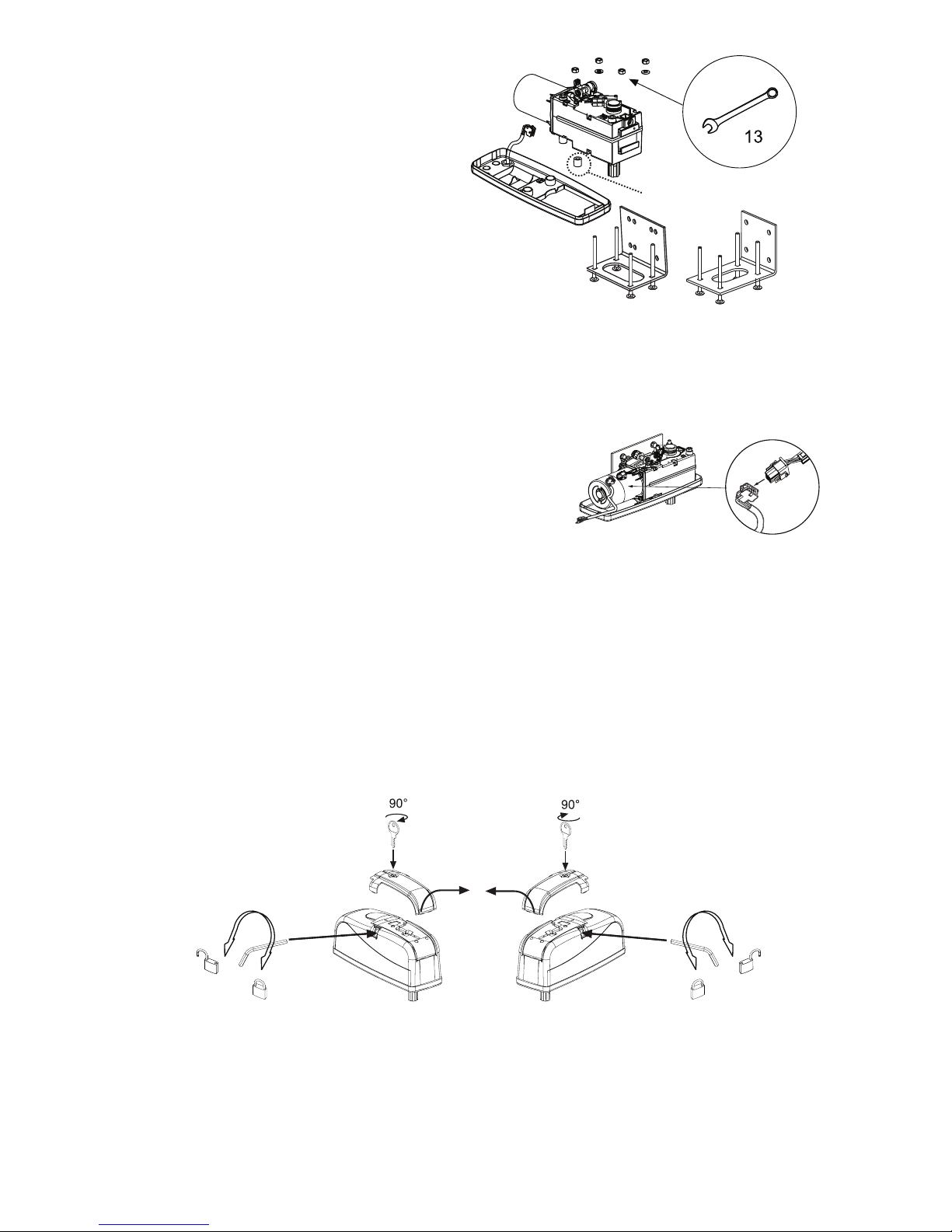
Step 2 Prepare the Motor Housing
Taking note of the the Motorʼs orientation, carefully knock
out one of the four tap in the base housing as illustrated to
allow for cable entry. Several openings for the cable have
been pre-punched in the base and need only be broken
through. Place the base plate onto a solid surface whilst
breaking the holes through to prevent the PVC base plate
from breaking. A small, flat screwdriver should be used for
breaking the holes through. For this purpose, tap on the
screwdriver handle with the palm of the hand from the inside. Repeat this as necessary at several points on the premarked circle. The pre-punched area can then be easily
removed and the strain relief supplied as standard fitted in
its place.
Thread the Terminated Loom through the gland nut and into
the hole knocked out for cable entry. Thread the gland over
the cable and through the knockout hole as illustrated. Fasten the Gland in place firmly with the nut. Hand tighten the
bottom nut, allowing around 200mm of cable to protrude.
Knock out
PILLAR SIDE
Gate
Wall or
Pillar
Page 6
5
S
tep 3 Mounting the motor to the Wall Bracket.
Once the Wall Bracket has been mounted, the drive can be
fitted. The drives can be used left or right without conversion.
Using the hardware provided fit the Base Plate onto the Wall
Bracket. Place the Spacer provided into place as illustrated,
then insert the bolts provide through the square hole in the
Walll Bracket.
Ensure the connection cable is correctly positioned, and the
bolts are fitted correctly. Hand tighten the nuts to secure the
motor in postion, then using the washers and nuts provided
to fasten the motor securely in place using 13mm spanner
(not provided).
ART-7
Standard Base
Plate
ART-6
For Narrow
Pillars
or
Spacer
Step 4 Connect Motor to Loom.
Connect the Connection Cable in the motor as illustrated (fig1).
Step 5 Manual Release.
The release lock for the casing is located under the rubber waterproof cover. Use the socket spanner supplied in the
hardware bag to lift the cover up. The release key located beneath the hood should be inserted into the side openings
and turned approx. 180 degrees until it cannot turn any further. The drive has now been released. To re-engage it, the
key should be turned back to its original position.
NOTE: Take care when unlatching the drive for manual operation. The gate panel can move in an uncontrolled
way, especially if it is mounted in a sloped position.
fig 1
Page 7
6
I N S T A L L A T I O N
To prevent SERIOUS INJURY or DEATH from a moving gate:
• Entrapment protection devices MUST be installed to protect
anyone who may come near a moving gate.
• Locate entrapment protection devices to protect in BOTH
the open and close gate cycles.
• Locate entrapment protection devices to protect between
moving gate and RIGID objects, such as posts.
• A swinging gate shall NOT open into public access ways.
01-G0665F18
SA FETY PREC A UTIO NS FOR SW ING an d O RNAM ENTAL “G RILL TY P E GATE S”
NOTE: It is recommended an E-lock or Maglock be used on gates over 2m for added security against vandalism and adverse
weather.
Disengage
A=38,5cm
8,5cm
30cm
C
B=60-70cm
7-8 cm = 90°
m
ax. 10 cm
=
Step 6 Fit the Gate Arm.
Use the Relase Key provided in your hardware bag to
Disenage the Motor by turning the Hex head nut located
on the top of the motor.
Assemble your Gate Arm and fasten in place using the
bolt and washer provided.
The Gate Arm exerts considerable forces on the gate and
all fixings. For this reason the Gate Arm MUST BE FASTENED SECURELY to the gate frame. Where possible
Weld the bracket in place for metal gates. For Timber
gates through bolts should be used.
Use the Mounting Requiments outlined below for mounting requirements and bracket locations.
Page 8

7
S A F E T Y I N S T A L L A T I O N I N F O R M AT I O N
Warning - To reduce the risk of SEVERE INJURY or DEATH from an incorrect installation:
1. Vehicular gate systems provide convenience and security. Gate systems are comprised of many component parts. The gate operator is only one component. Each gate system is specifically designed for an individual application.
2. Gate operating system designers, installers and users must take into account the possible hazards associated with each individual
component. Poorly designed, installed or maintained gate systems may be dangerous to users and bystanders. Gate installers
and designers should therefore take steps to reduce the publicʼs exposure to potential hazards.
3. A gate operator can generate a great deal of force during operation, installers must be mindful of this fact. Safety features must be
incorporated into every design. Specific safety features include:
•
Gate Edges • Guards for exposed rollers • Photoelectric Sensors
• Vertical Posts • Instructional and Precautionary Signage
4
. A gate opener should only be installed where:
a. The operator is appropriate for the construction and the usage class of the gate.
b
. All exposed pinch points are eliminated or guarded, and guarding is supplied for exposed rollers.
5. The operator is intended for installation only on vehicular gates only, pedestrians should be supplied with a seperate access
6
. The gate must be installed in a location so that enough clearance is supplied between the gate and adjacent structures when
opening and closing to reduce the risk of entrapment. Swinging gates shall not open into public access areas.
7. The gate must be properly installed and work freely in both directions prior to the installation of the gate operator.
8. Controls must be far enough from the gate so that the user is prevented from coming in contact with the gate while operating the
controls.
9. Any warning signs must be clearly visible, on each side of the gate.
10. For a gate operator utilising a non-contact sensor:
a. Reference ownerʼs manual regarding placement of non-contact sensor for each type of application.
b. Care shall be exercised to reduce the risk of nuisance tripping, such as when a vehicle trips the sensor while the gate is still
moving.
c. One or more non-contact sensors shall be located where the risk of entrapment or obstruction exists, such as the perimeter
reachable by a moving gate or barrier.
11. For a gate operator utilizing a contact sensor such as an edge sensor:
a. A hard wired contact sensor shall be located and its wiring arranged so the communication between the sensor and the gate
operator is not subject to mechanical damage.
b. A wireless contact sensor such as the one that transmits radio frequency (RF) signals to the gate operator for entrapment pro-
tection functions shall be located where the transmission of the signals are not obstructed or impeded by building structures,
natural landscaping or similar obstruction. A wireless contact sensor shall function under the intended end-use conditions.
c. One or more contact sensors shall be located at the leading edge, trailing edge and post mounted both inside and outside of a
vehicular horizontal slide gate.
d. One or more contact sensors shall be located at the bottom edge of a vehicular vertical lift gate.
e. One or more contact sensors shall be located on the inside and outside leading edge of a swing gate. Additionally, if the bottom
edge of a swing gate is greater than 15cm (6”) above the ground at any point in its arc of travel, one or more contact sensors
shall be located on the bottom edge.
IMPO RTANT SAFE OPERATING/MAINTENANCE
INSTRUCTIONS
To reduce the risk of SEVERE INJURY or DEATH:
1. READ AND FOLLOW ALL INSTRUCTIONS.
2. NEVER allow children to operate or play with gate
controls. Keep the remote control away from children.
3. ALWAYS keep people and objects away from the
gate. NO ONE SHOULD CROSS THE PATH OF
THE MOVING GATE.
4. Test the gate operator monthly. The gate MUST reverse on contact with a rigid object or stop when an
object activates the non-contact sensors. After adjusting the force or the limit of travel, retest the gate
operator. Failure to adjust and retest the gate operator properly can increase the risk of INJURY or
DEATH.
5. Use the manual release ONLY when the gate is not
moving.
6. KEEP GATES PROPERLY MAINTAINED. Read the
ownerʼs manual. Have a qualified service person
make repairs to gate hardware.
7. The entrance is for vehicles ONLY. Pedestrians
MUST use separate entrance.
8. This appliance is not intended for use by persons
(including children) with reduced physical sensory or
mental capabilities, or lack of experience and
knowledge, unless they have been given supervision
or instruction concerning use of the appliance by a
person responsible for their safety.
Page 9
8
* Solar Powered Panels - The size of these depends on: the duty cycle of the gates; the hours of sunlight; and the number and type of accessories fitted. 30 watts is recommended for Residential use. The
conductor size needs to be in accordance with Table 1 below, as a minimum.
* Battery Powered with trickle charging - Due to the high cost of long runs of heavy cable, it may be more
economical in some installations to operate the gates from a battery, which is charged from a remotely
located trickle charger.
For example: a 15 VAC 2.5 Amp plug pack can be
located at the house, with appropriate wiring to the
gate, controller, and battery some distance away.
Follow Table 1 for minimum recommended
conductor sizes for different distances.
WIRING: All wiring must be arranged to prevent water
entering the controller enclosure. Do not wire mains
voltage and low voltage control wires in the same conduit.
* Low voltage motor cable sizes - Voltage will drop along
low voltage cables over long distances. It is
recommended to use cable with conductors of the
following minimum cross sectional areas. Table 2
lists lengths for twin-core cable, from a 12 V supply and
5 Amp load.
Cable length
Conductor size mm
AWG#
Up to 30 m 1.5 mm 16
Up to 100 m 2.5 mm 14
2
2
2
Cable length
Conductor size mm
AWG#
3 m 1.5 mm 16
5 m 2.5 mm 14
10 m 4 mm 12
15 m 6 mm 10
20 m 10 mm 8
2
2
2
2
2
2
TABLE 2 - Motor Cable
TABLE 1
C A B L E S I Z E S
Main Output (Motor) 12vdc Battery run,Operational
between 11vdc and 14vdc.
Accessory power 12vdc nominal Class II battery
(500ma max length conversion)
Power Consumption 30 Watts max (during battery
Charging).
T
emperature -20
o
C
to +50
o
C
Protection Fuse Battery 1 ATC20A
Protection Fuse Battery 2 ATC20A
C A R T O N I N V E N T O R Y
CB12ANZ CONTROL BOARD KIT
1x PVC – Box
1x CB12-Logic Board (pre-mount)
1x Charge transformer (pre-mount)
1x Antenna
S P E C I F I C AT I O N
Page 10
9
Transformer
Transformer
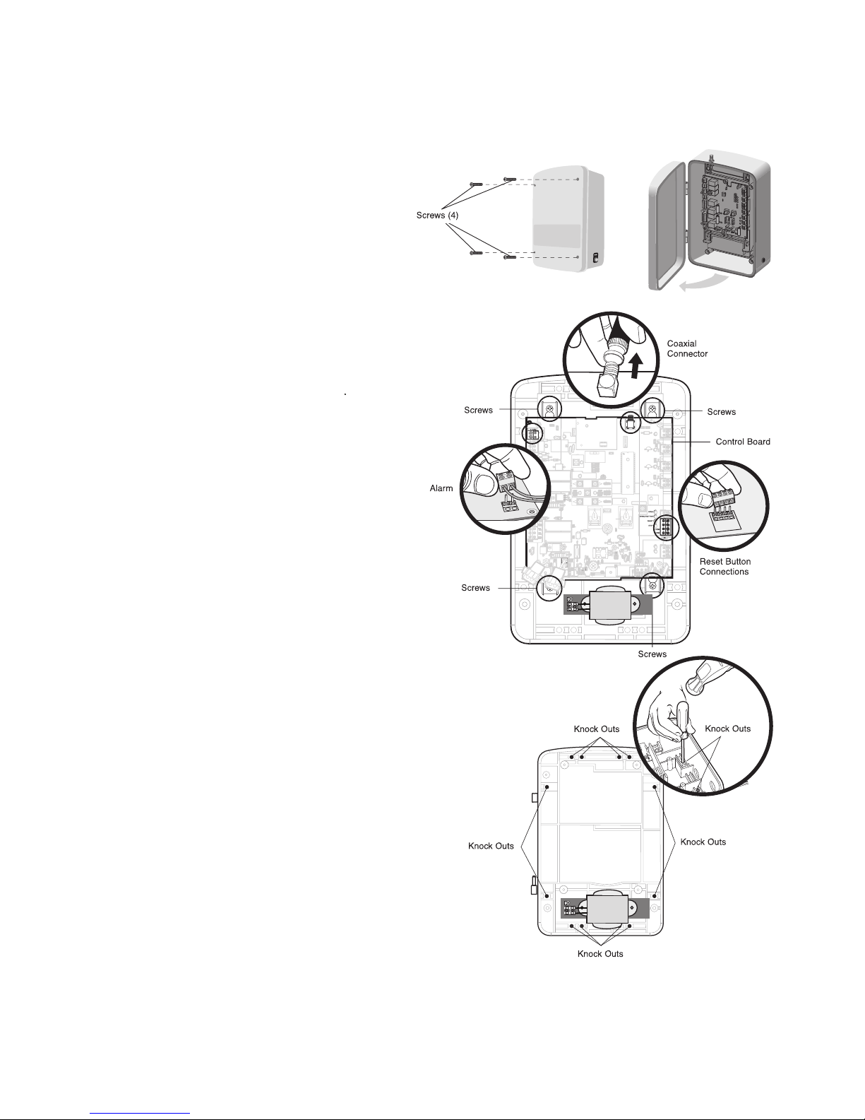
Mount the Control Box
T
he control box MUST be mounted within 1.5m of the
gate operator. Mount the control box as high as possible
for best radio reception
1. Open the Control Box
Remove the screws and open the box.
3. Select Mounting Holes
Select holes to be used for mounting and knock out using
a screw driver and hammer.
2. Remove the Control Board
Disconnect reset button, alarm and internal coaxial
connector. Loosen screws and remove Control Board.
Set aside IR beams, remotes, antenna, hardware bag*
and battery looms.
*Hardware bag includes, cable glands, fixing screws,
replacement fuse and three wire nuts.
Page 11

10
Antenna
U-Bolt
(
Not Provided)
Wall
Concrete
Anchor
Square
Gate Post
Screw
1818
L1L1
K2K2
Z22Z22
F2F2
MOV1MOV1
D1D1
OPEN
S
INGLEBUTTON
R
ESET
STOP
CHGRCHGR
OVLDOVLD
C
OM
COM
D129D129
Z4Z4
D2D2
C11C11
C13C13
D16D16
F9F9
K1K1
F
3F3
K3K3
K4K4
F1F1
Z12Z12
GATE2GATE 2
GATE1
GRGR
WHWH
YLYL
BLBL
R
DRD
BRBR
GRGR
WHWH
Y
LYL
B
LBL
RDRD
BRBR
F
7F7
24V24V
CTRLCTRL
OVLDOVLD
TIMERTIMER
RUNNINGRUNNING
G
ATE2GATE 2
S
ETSET
O
PENOPEN
LIMITLIMIT
S
ETSET
C
LOSECLOSE
LIMITLIMIT
L
EARNLEARN
LIMITSLIMITS
GATE1GATE 1
LEARNLEARN
XMITTERXMITTER
L
OCK/LOCK /
O
NON OFFOFF
C69C69
PWRPWR
ACPWRACPWR
/SOLAR/SOLAR
R329R329
R27R27
MOV2MOV2
R4R4
C2C2
B
IPART DELAYBIPART DELAY
L
OCK
Q9Q9
R9R9
ØØ
F
8F8
C
73C73
C
72C72
C71C71
C7C7
ØØ
R42R42
Ø
Ø
R
423R423
J24 J23 3J24 J23 3
ØØ
A 32VA 32V
3 3
ØØ
A 32VA 32V
J21J21
3030
3030
C64C64
R22R22
U
2U2
K6K6
JU1JU1
JU1JU1
J
U2JU2
DB1DB1
R
184R184
A
LARM
1818
K2K2
Z22Z22
F2F2
MOV1MOV1
D1D1
D
129D129
Z4Z4
D2D2
C11C11
C13C13
D16D16
F9F9
K1K1
F3F3
K3K3
K4K4
F1F1
Z12Z12
GATE2GATE 2
G
RGR
W
HWH
YLYL
B
LBL
R
DRD
B
RBR
F7F7
24V24V
GATE2GATE 2
SETSET
OPENOPEN
LIMITLIMIT
S
ETSET
CLOSECLOSE
LIMITLIMIT
L
EARNLEARN
L
IMITSLIMITS
GATE1GATE 1
C69C69
R329R329
R27R27
MOV2MOV2
R4R4
C2C2
Q9Q9
R9R9
ØØ
F8F8
C73C73
C72C72
C71C71
C7C7
ØØ
R42R42
ØØ
R423R423
J24 J23 3J24 J23 3
ØØ
A 32VA 32V
3 3
ØØ
A 32VA 32V
J21J21
3030
3030
C64C64
R22R22
U2U2
K
6K6
JU1JU1
JU2JU2
D
B1DB1
Screws
Screws
Screws
Control Board
Reset Button
Connections
Coaxial
C
onnector
Alarm
Battery 1Battery 1
Single GateSingle Gate
Battery 2Battery 2
Two GatesTwo Gates
Transformer
Transformer
Screws
IMPORTANT NOTE:
E
nsure watertight
connection seal
with silicon sealant
FAILURE to ensure
watertight seals may
render your product
unusable and will
v
oid warranty
4. MOUNT THE CONTROL BOX
Secure the control box to mounting surface (post, wall, column,
etc.) using the four fixing screws provided. If fixing to masonary
or tube steel you will require additional hardware (not provided).
5. INSTALL THE BATTERY/BATTERIES AND CONTROL BOARD
Attach antenna. Install batteries and connect battery looms. Reinstall
control board, alarm, and reset button. Re-connect internal coaxial connector.
NOTE: Make sure battery leads are on the left side of the control box
and not pinched.
Do NOT
connect battery looms to the control board at this time.
NOTE: Before proceeding to the next page, please ensure gate motors are installed.
IMPORTANT NOTE:
Waterproof all knockout holes using silicon sealant.
Page 12

11
Typical motor install
illustrated.
M
o
v
i
n
g
G
a
t
e
C
a
n
C
a
u
s
e
I
n
j
u
r
y
o
r
D
e
a
t
h
K
E
E
P
C
L
E
A
R
!
G
a
t
e
m
a
y
m
o
v
e
a
t
a
n
y
t
i
m
e
w
i
t
h
o
u
t
p
r
i
o
r
w
a
r
n
i
n
g
.
D
o
n
o
t
l
e
t
c
h
i
l
d
r
e
n
o
p
e
r
a
t
e
t
h
e
g
a
t
e
o
r
p
l
a
y
i
n
t
h
e
g
a
t
e
a
r
e
a
.
T
h
i
s
e
n
t
r
a
n
c
e
i
s
f
o
r
v
e
h
i
c
l
e
s
o
n
l
y
P
e
d
e
s
t
r
i
a
n
s
m
u
s
t
u
s
e
s
e
p
a
r
a
t
e
e
n
t
r
a
n
c
e
W
atertight Connector Nut (Provided)
Please observe the WARNINGS outlined on Pages 1 and 7 of this manual.
Page 13

12
Z
22
R
91
C
LOSE
EDGE
R
94
R92
R93
L
1
R1
R2
Z
1
K5
K6
K2
F3
1
0A32V
D
1
Ø
OPENEDGE/
P
HOTO
OPEN
P
HOTO
CLOSE
P
HOTO
R227
R2
Ø
7
Z2
Ø
R
223
P1
Z9
Z8
F
2
F6
D4D2R9
C64
JMPR1
R
224
U4
CONTROL
I
NPUTS
FORCE
TIMERTO
CLOSE
OFF MAX
O
PEN
SINGLEBUTTON
R
ESET
STOP
SHADOW
I
NTERRUPT
C
HGR
OVLD
COM
C
OM
COM
F
USE
OPEN
LOOP
I
NPUTS
P
OWER
BATT1BATT2
F120A 32V
R35
D9
Z3
Z
4
U3
D1
D
27
F
5
C11
C13
C12
D15
4
R 2C
R
1
Ø
1
R1
ØØ
R9
Ø
Q
9
K
1
R196
Q
22
D8
K3
K
4
D21
D22
C
4
A
CCESSORY
O
VLD
D6
JMPR2
M
OV1
M
OV2
D
B1
U2
Z12
24VAC/
SOLAR
INPUT
G
ATE2
A
CCESSORY
POWER
M
AGLOCK
A
LARM
GATE1
C
C
NC
NO
NO
GRN
WHT
YEL
BLU
RED
BRN
GRN
WHT
YEL
BLU
RED
BRN
F
4
1
0A32V
F7
24V
C
OM
O
VLD
TIMER
RUNNING
GATE2
S
ET
OPEN
LIMIT
S
ET
CLOSE
LIMIT
LEARN
LIMITS
DIAGNOSTIC
G
ATE1
J
4
L
EARN
XMITTER
MAGLOCK
ON OFF
F2
F6
U4
M
AX
FUSE
OPEN
C13
C4
Z1
10
D1Ø
Z12
ACCESSORY
P
OWER
GATE 1
GRN
WHT
YEL
BLU
RED
BRN
T
erminal blocks
c
an be removed
t
o simplify wiring.
B
rown
G
reen
W
hite
Y
ellow
B
lue
R
ed
Watertight Connector Nut
O
perator Cable
CONTROL BOX
Transformer
M
o
v
i
n
g
G
a
t
e
C
a
n
C
a
u
s
e
I
n
j
u
r
y
o
r
D
e
a
t
h
K
E
E
P
C
L
E
A
R
!
G
a
t
e
m
a
y
m
o
v
e
a
t
a
n
y
t
i
m
e
w
i
t
h
o
u
t
p
r
i
o
r
w
a
r
n
i
n
g
.
D
o
n
o
t
l
e
t
c
h
i
l
d
r
e
n
o
p
e
r
a
t
e
t
h
e
g
a
t
e
o
r
p
l
a
y
i
n
t
h
e
g
a
t
e
a
r
e
a
.
T
h
i
s
e
n
t
r
a
n
c
e
i
s
f
o
r
v
e
h
i
c
l
e
s
o
n
l
y
P
e
d
e
s
t
r
i
a
n
s
m
u
s
t
u
s
e
s
e
p
a
r
a
t
e
e
n
t
r
a
n
c
e
Operator Cable
3. CONNECT OPERATOR TO CONTROL BOARD
Extend operator cable and wires to GATE 1 connector and connect as shown.
Tighten watertight connector nut.
IF INSTALLING ONE OPERATOR, PROCEED TO PAGE 15.
If installing two operators, continue to the next page.
Page 14

13
T
ransformer
M
o
v
i
n
g
G
a
t
e
C
a
n
C
a
u
s
e
I
n
j
u
r
y
o
r
D
e
a
t
h
K
E
E
P
C
L
E
A
R
!
G
a
t
e
m
a
y
m
o
v
e
a
t
a
n
y
t
i
m
e
w
i
t
h
o
u
t
p
r
i
o
r
w
a
r
n
i
n
g
D
o
n
o
t
l
e
t
c
h
i
l
d
r
e
n
o
p
e
r
a
t
e
t
h
e
g
a
t
e
o
r
p
l
a
y
i
n
t
h
e
g
a
t
e
a
r
e
a
T
h
i
s
e
n
t
r
a
n
c
e
i
s
f
o
r
v
e
h
i
c
l
e
s
o
n
l
y
P
e
d
e
s
t
r
i
a
n
s
m
u
s
t
u
s
e
s
e
p
a
r
a
t
e
e
n
t
r
a
n
c
e
1. CONNECT SECOND OPERATOR TO CONTROL BOARD MGA600
NOTE: Junction box and extension kit part number JB12M is included in the slave kit
(MGA600S) for this function.
• Before digging, contact local underground utility locating companies.
• Trench across driveway to bury the extension cable.
• Use PVC conduit to prevent damage to cables.
• Insert extension cable through watertight connector nut and through an available
watertight connector mounted in the control box.
• Extend cable and wires to GATE 2 connector and connect as shown.
• Secure extension cable to control box using watertight connector nut.
FAILURE TO INSTALL THE SLAVE OPENER WITH CORRECT CABLE WILL VOID YOUR
WARRANTY.
Page 15

14
Transformer
Page 16

15
IIRR SSAAFFEETTYY BBEEAAMMSS 777722AANNZZ
IR Safety Beams are recommended to reduce the risk of personal injury and vehicle damage.
EN1243 specifies that IR Beams be installed at a height of 200 mm and activated
t
o “close”.
The sensors consist of a transmitter and receiver installed opposite to each other
across the gate access.
INSTALLATION
Install the beams opposite each other in the position required to maintain safe
access, using small screws and wall plugs.
Using suitable cable, (2 wire) connect the beams to each other and to the control
box Safety Sensor inputs (see wiring diagram page 24).
Use “open” photo and “Closed” photo as required.
PROGRAMMING of IR BEAMS
This is automatically achieved when programming the “Travel Limits” of the gate.
See programming section.
IR BEAM DIAGNOSTIC LEDs
NOTE: Remove sensor covers to access.
LED ON = Power and alignment OK
LED FLASHING = Obstruction or misalignment
LED OFF = No power or sleep mode
TO DISABLE IR BEAMS - remove wires from the terminals and reset limits.
See programming section.
+
+
+
772ANZ - Removing Cover
Page 17

16
Control Box
External GPO
CAUTION!
240 VAC
1
818
R93
L1L1
K2K2
Z22Z22
P1P1
F2F2
MOV1MOV1
D1D1
Q12Q12
U4U4
OFFOFF MAXMAX
OPEN
SINGLE BUTTON
RESET
STOP
CHGR
O
VLD
CTRL PWR
COM
D
129D129
Z4Z4
U3U3
D2D2
D44D44
C11C11
C13C13
C12C12
D16D16
F9F9
R1R1ØØ11
R1R1
ØØØØ
Q
22Q22
F3F3
K3K3
K4K4
R196R196
F1F1
G
ATE 2GATE 2
G
ATE 1GATE 1
GRGR
WHWH
Y
LYL
B
LBL
RDRD
BRBR
F7F7
24V24V
C
TRL
OVLD
T
IMERTIMER
RUNNINGRUNNING
GATE 2GATE 2
SETSET
OPEN
SETSET
CLOSECLOSE
LIMITLIMIT
L
EARNLEARN
L
IMITSLIMITS
GATE 1GATE 1
LOCK /LOCK /
ONON OFFOFF
C69C69
O
FFOFF MAXMAX
J2J2
ØØ
P
WR
AC PWR
/SOLAR
D8D8
D4D4
R9R9
R329R329
R27R27
R4
C2C2
B
IPART DELAYBIPART DELAY
LOCKLOCK
R9R9
ØØ
Q6Q6
J19J19
R182R182
C1
Ø1Ø1
C
75C75
C73C73
C72C72
C
71C71
C7C7
ØØ
C66C66 C65C65
C68C68
C33C33
F11F11
R186R186
R
42R42
ØØ
R423R423
J24 J23 3J24 J23 3
ØØ
A 32VA 32V
3 3
ØØ
A 32VA 32V
J21J21
3030
3030
C64C64
R22R22
U2U2
J18J18
K6K6
JU1JU1
JU1JU1
JU2JU2
DB1DB1
R184R184
MOV1MOV1
CHGR
OVLD
AC PWR
/SOLAR
MOV2
R4
C2
JU1
LE BUTTON
K2
K1K1
SET
OPEN
LIMIT
C73
C
72
C71
DIAGNOSTIC
OPEN
SINGLE BUTTON
RESET
STOP
C
TRL PWR
CTRL
OVLD
PWR
C
ONNECTING OPTIONAL SOLAR PANEL (NOT SUPPLIED)
If you are using a SOLAR PANEL, the Transformer MUST be unplugged and removed.
Terminate the Solar Panel into the AC PWR/SOLAR Terminals as illustrated below.
N
OTE: Solar Panel should be 12 Volt, up to 30 Watt with class 2 output.
Two batteries are also recommended for solar systems.
CONNECTING POWER TO THE CONTROL BOARD UNIT
For outdoor connection, a properly earthed WEATHER PROOF POWER
POINT MUST BE USED.
NOTE: Connection of Power must comply to local electrical standards.
Page 18

17
1
8
18
R
93
R93
L
1
L1
D42
D42
K2
K2
D
1
D1
Ø
Ø
Z22
Z22
P1
P1
F2
F2
MOV1
MOV1
D1
D1
Q12
Q12
U
4
U4
OFF
OFF
MAX
MAX
OPEN
OPEN
SINGLE BUTTON
SINGLE BUTTON
R
ESET
RESET
STOP
STOP
CHGR
CHGR
OVLD
OVLD
COM
COM
COM
COM
D129
D129
Z4
Z4
U
3
3
U
D2
D2
D
44
D44
C11
C11
C
13
C13
C12
C12
D16
D16
F9
F9
R1
R1ØØ11
R1
R1
Ø
Ø
ØØ
K1
K1
Q
22
Q22
F
3
F3
K3
K3
K4
K4
R
196
R196
F
1
F1
Z12
Z12
GATE 2
GATE 2
G
ATE 1
G
ATE 1
MAGR
MAGR
S
OL
SOL
GR
GR
WH
WH
YL
YL
BL
BL
RD
RD
B
R
BR
GR
GR
WH
WH
YL
YL
BL
BL
RD
RD
B
R
BR
F7
F7
24V
24V
CTRL
CTRL
O
VLD
OVLD
T
IMER
TIMER
RUNNING
RUNNING
GATE 2
GATE 2
S
ET
SET
O
PEN
OPEN
LIMIT
LIMIT
S
ET
SET
C
LOSE
CLOSE
LIMIT
LIMIT
LEARN
LEARN
L
IMITS
LIMITS
GATE 1
GATE 1
L
EARN
LEARN
XMITTER
XMITTER
LOCK /
LOCK /
ONONOFF
OFF
C69
C69
O
FF
OFF
M
AX
MAX
J2
J2
Ø
Ø
PWR
PWR
AC PWR
AC PWR
/
SOLAR
/SOLAR
D8
D8
D4
D4
R9
R9
R329
R329
R27
R27
MOV2
MOV2
R4
R4
C2
C2
B
IPART DELAY
BI
PART DELAY
L
OCK
LOCK
GND
GND
Z
1
Z1
R1
R1
R
2
R2
K5
K5
F
12
F12
Q9
Q9
R
9
R9
ØØ
F
8
F8
Q6
Q6
Q1
Q1
J19
J19
R182
R182
C1
C1
Ø
1
Ø1
C
75
C75
C
73
C73
C
72
C72
C71
C71
C7
C7
ØØ
C66
C66
C65
C65
C68
C68
C33
C33
F11
F11
R186
R186
R
42
R42
Ø
Ø
R
423
R423
J24 J23 3
J24 J23 3
Ø
Ø
A 32V
A 32V
3
3
Ø
Ø
A 32V
A 32V
J21
J21
30
30
30
30
C64
C64
R
22
R22
U
2
U2
J18
J18
K
6
K6
JU1
JU1
JU1
JU1
JU2
JU2
D
B1
DB1
D
36
D36
R
184
R184
Battery Connectors
Battery Connection (dual gate/solar)
Battery Connection (single gate)
Battery Connectors
Control Board
Board Connectors
Board Connectors
OR
CONNECT BATTERIES
The batteries are charged in circuit by using the transformer (provided).
Locate the two white battery plugs on the left-hand side of the control box.
Connect the plug from the battery to connector on the control board. Either connector can be used for a single battery.
NOTES: Batteries will degrade over time depending on temperature and usage. For best performance, the batteries
s
hould be changed every 3 years. Batteries do not perform well in extremely cold temperatures. For locations where
the temperatures are below -20° C (-4°F) contact technical support.
Page 19

18
Closed position
Open position
Use a screwdriver to push the CAM firmly to the
position.
Note: Firmly push the holes on top of the CAM to adjust.
To avoid burring the CAM do not push directly on the cam lobe.
CLICK
Micro switch should be starting to engage.
Adjust CAM so that you hear a click 10 degrees
BEFORE the gate is fully open.
Micro switch should be starting to engage.
Adjust CAM so that you hear a click 10 degrees
BEFORE the gate is closed.
SSEETTTTIINNGG TTHHEE CCAAMMSS FFOORR MMGGAA660000
The CAM switches must be set before proceeding with
any programming. Either CAM can be used for “open”
or “closed” position.
To set the CAM switches, disengage the motor using
the Hex key provided.
R
emove the top cover of the motor to allow access to
the CAM located at the top of the motor (keys to acc
ess the cover are provided with the gate operator).
Manually move the gate through one complete action.
The micro switches make a clicking sound as the CAM
begins to engage them.
Open Limit:
Set the CAM so the open limit microswitches click about 10 degrees before the desired open position.
Closed Limit:
The closed limit microswitch should click about 10 degrees before the gate is at the desired closed position.
NOTE: The cams are set for use as passpoints (references) NOT THE OPEN AND CLOSED POSITIONS.
A useful rule of thumb is to set the click to the point at which the soft stop & soft stop engage.
Limit programming detailed on pages 19 and 20.
Page 20

19
Page 21

20
left
r
ight
NOTES:
Page 22

21
TIMER TO
CLOSE
TTC can be temporarily disabled by pressing RESET
button (located on the outside side of the control box)
when the gate is fully open. This will allow the gate to
remain open until another command is received. After
the next command to the operator, TTC returns to the
previously set time period.
TTC OFF MAXIMUM time
180 seconds
Page 23

22
C840
Page 24

23
MANUAL RELEASE
The release lock for the casing is located under the rubber
weatherproof cover. Use the socket spanner supplied in the
hardware bag to lift the cover up. The release key located beneath the hood should be inserted into the side openings and
turned approx. 180 degrees until it cannot turn any further. The
drive has now been released. To re-engage it, the key should
be turned back to its original position.
NOTE: Take care when unlatching the drive for manual
operation. The gate panel can move in an unconditional way,
especially if it is mounted oin a sloped postion.
OPERATION OF YOUR GATE OPENER
Page 25

24
CAUTION!
240 VAC
Transformer
Page 26

25
CCOONNTTRROOLL IINNPPUUTTSS
Refer to Wiring Diagram on page 24.
WIRE STOP BUTTON (OPTIONAL)
A jumper wire is factory installed between the stop and
common input.
Stop (N/C) - Stop only (does not reset alarm).
NOTE: Stop jumper is required for normal operation
(
the Stop LED will be lit except when the control board
goes into Sleep Mode). Remove only if remotely
mounted Stop button is added.
OPEN
Opens only or reverses a closing gate.
SBC (SINGLE BUTTON CONTROL) INPUT
This input will command the gate to
OPEN / STOP / CLOSE / STOP in sequence.
RESET CONTROL INPUT
The control box has a factory installed internal reset button.
These terminals are intended for use with a single reset
button that is installed within a line of sight of the gate.
This input functions to reset the alarms. This input will
NOT stop the gate.
NOTE: All control inputs must be Normally Open (N.O.)
dry contact type.
C2
CONTROL
INPUTS
OPEN
SINGLE BUTTON
RESET
STOP
COM
COM
C
OM
COM
M
M
CONTROL
INPUTS
OPEN
SINGLE BUT TO N
RESET
STOP
POWER
CONTROL
INPUTS
OPEN
SINGLE BUTTON
RESET
STOP
COM
COM
COM
COM
M
M
CONTROL
INPUTS
OPEN
SINGLE BUT TO N
RESET
STOP
POWER
Page 27

26
Page 28

27
Page 29

28
Page 30

29
SYMPTOM POSSIBLE SOLUTION
Gate opens but does not • An open input is continuously activated. Check the open loop or vehicle probe to
eseht rof noitarepo dna snoitcennoc yfireV .stcejbo fo raelc era yeht erus ekam .esolc
.secived
• Low battery. Measure the voltage across the battery. Voltage should be above
11.5Vdc. Replace battery if required.
• (Optional Accessory) Entry system output is connected to the OPEN input, and is
“stuck” opening. Verify entry system connections and operations.
• Obstruction blocking close photo eyes, shadow loop, or safety loop. Check eyes for
alignment and verify all connections and operation for safety devices.
• (Optional Accessory) Close safety edge is damaged or on an obstruction. Verify
operation and connection of close edge.
.yaled derised ot detsujda dna NO si esolC ot remiT eht taht yfireV • esolc ton seod etaG
automatically with Timer to • Gate opened by a force obstruction reversal. Check the Diagnostic LED and clear
Close enabled. gate path of any obstructions.
• The Interrupt loop or Shadow loop is obstructed (optional accessories).
• Obstructed close safety sensor or safety edge (optional accessory). Check
connections and operations of safety devices.
• Low battery. Measure the voltage across the battery. Voltage should be above
11.5Vdc. Replace battery if required.
• An open input is continuously activated. Check the open loop or vehicle probe to
make sure they are clear of objects. Verify connections and operation for these
devices.
• (Optional Accessory) Entry system output is connected to the OPEN input, and is
“stuck” opening. Verify entry system connections and operation.
• Operator in “Party” mode after RESET button pressed while at the OPEN limit. Use
a remote or the SBC to close the gate and reopen it. Verify that the
TIMER RUNNING LED is flashing.
Alarm constantly sounds • Double entrapment occurred. Two successive obstructions were encountered while
for 5 minutes. Sounds moving the gate. Press the RESET button and ensure that the gate path is clear of
whenever a command is all obstructions. Check the FORCE setting to make sure it is properly set.
issued.
Alarm is beeping 3 times on • Low battery. Measure the voltage across the battery. Voltage should be above
a command. 11.5Vdc. Replace battery if required.
era stimiL esolC dna nepO eht fI .rehtegot esolc oot tes era stimiL esolC dna nepO • .wols oot snur etaG
set within the ramp down distance of each other, the gate will run at slow speed all
the time.
• The gate is starting within the ramp down distance from the Open or Close Limit.
Gate will run slow to limits if motion is started within the ramp-down distance from
the limit.
taht yfireV .NO ot hctiws yaleD trapiB/kcoL eht edilS .tes ton yaleD trapiB/kcoL • .1 etaG erofeb sesolc 2 etaG
Gate 1 starts moving first on open and last on close.
• Gate is excessively heavy or hinges are bad. Verify that the gate is within the ratings
for this product. Disconnect the arms and verify that both gates swing easily.
Lubricate or replace hinges as necessary.
• Gate is unbalanced. Disconnect the arms and verify that both gates swing easily in
both directions. If the gates are harder to move in one direction verses the other, the
gate is not properly balanced and the hinges must be adjusted.
• Bad motor connection. Check the motor wires and connections for possible loose or
corroded terminals.
evoba eb dluohs egatloV .yrettab eht ssorca egatlov eht erusaeM .yrettab woL • .gninnur nehw speeb mralA
11.5Vdc. Replace battery if required.
Gate does not open/close at • In windy areas, an automatic gate lock for close and a hard stop for open is
the same place each time. recommended to ensure the gate stops in the same place each time.
• Periodic limit adjustments may be necessary.
Page 31

30
ART-6
041AART-0007
041ABSC-0005
041ASWG-0454
ART-3AL
041AART-1022SA
041AART-1025SA
Antenna 001C3196-3
K001A6426
041AART-1002SA
041AART-1004
041AART-0003
041ABSC-1010
041AART-1005
041ABSC-1011
041AART-0063SA
041ABSC-0027
041ABSC-0017
041AART-0010
041AART-0002
041AART-1003SA
041ASLG-0054K
ART-2
SSPPAARREESS
Page 32

31
01-36622
5 problems caused by electrical faults or replacement of batteries;
6 water or moisture ingress that causes corrosion or electrical
malfunction;
7 corrosion caused by sea air if located near a waterway, beach etc;
8 fitment in a commercial operating application; or
9 solid panel gates installed in an unprotected wind affected location
resulting in the gate not closing;
10 non use of cable provided for second gate arm connection.
NB: A General Purpose Outlet (GPO) ie: power point must be supplied
by the consumer as this electrical fitting does not form a part of the
Unit (opener). Excludes solar installations.
If this Chamberlain Limited Warranty does not apply, you may have
rights available to you under the Australian Consumer Law.
Liability – Australia only
Except as set out in the Australian Consumer Law (being Schedule 2
of the Competition and Consumer Act 2010) (as amended, consolidated or replaced):
1 all other guarantees, warranties and representations in relation to
the Unit or its supply are excluded to the extent that Chamberlain
can lawfully exclude them; and
2 under no circumstances will Chamberlain be liable for
consequential, incidental or special damages arising in connection
with the use, or inability to use, the Unit, other than those which
were reasonably foreseeable as liable to result from the failure.
Liability – New Zealand only
Except as set out in the Fair Trading Act 1986 and the Consumer
Guarantees Act 1993 (as amended, consolidated or replaced):
1 all other guarantees, warranties and representations in relation to
the Unit or its supply are excluded to the extent that
Chamberlain can lawfully exclude them; and
2 under no circumstances will Chamberlain be liable for
consequential, incidental or special damages arising in connection
with the use, or inability to use, the Unit, other than those which
were reasonably foreseeable as liable to result from the failure.
Note: We request that you retain your sales docket or invoice as
proof-of-purchase and attach it to this manual to enable you to
establish the date of purchase in the unlikely event of a warranty
service being required. Chamberlain reserves the right to change
the design and specifications of the Unit without prior
notification. Some features or accessories of the Unit may not be
available in certain markets or areas. Please check with your distributor.
Chamberlain service centre contact details
Australia
Phone toll free 1800 638 234
Fax toll free 1800 888 121
Chamberlain Australia Pty. Ltd.
PO BOX 1446
Lane Cove NSW 1595
New Zealand
Auckland phone 09 477 2823
Phone toll free 0800 653 667
Fax toll free 0800 653 663
Email: customerservice@chamberlainanz.com
Website: www.go-merlin.com
CHAMBERLAIN LIMITED WARRANTY
Merlin Professional MGA600
Articulated Swing Gate Opener
Chamberlain Australia Pty Limited / Chamberlain New Zealand Limited
(Chamberlain), the manufacturer of Merlin® automatic gate openers, is
committed to manufacturing and supplying high quality goods.
As part of this commitment, we seek to provide reliable service and
support for our goods and are pleased to provide you, the original purchaser, with this Chamberlain Limited Warranty.
We also provide the following statement as required by the Australian
Consumer Law: In Australia, in addition to your rights under this Chamberlain Limited Warranty, our goods come with guarantees that cannot
be excluded under the Australian Consumer Law. You are entitled to a
replacement or refund for a major failure and for compensation for any
other reasonably foreseeable loss or damage. You are also entitled to
have the goods repaired or replaced if the goods fail to be of acceptable
quality and the failure does not amount to a major failure.
Chamberlain’s warranty
Chamberlain warrants to the original purchaser of the Merlin® Swing
Gate Opener (Unit) that all parts of the Unit, other than remote controlled transmitters and accessories, globes and batteries, are free from
defects in materials and workmanship for a period of 24 months from the
date of purchase when installed in a residential premise with a residential specified gate that is designed for the sole purpose of domestic
domicile. Chamberlain warrants that remote controlled transmitters and
accessories included with the Unit are free from defects in materials
and workmanship for a period of 12 months from the date of purchase.
Batteries and globes are not covered under the Chamberlain Limited
Warranty.
It is a condition of this Chamberlain Limited Warranty that the Unit is
sold, installed and serviced by a Professional Dealer appointed by
Chamberlain. A Merlin® branded gate opener purchased over the internet and installed by a person other than a Professional Dealer will not
be covered by this Chamberlain Limited Warranty.
During the applicable Chamberlain Limited Warranty period, if you are
concerned that the Unit may be defective, for prompt on-site service call
the Professional Dealer that sold/installed the opener, or our service
centre on the toll free number below and a Chamberlain technician will
diagnose the problem and arrange for this to be rectified. Once the
problem has been diagnosed, subject to your rights under the Australian Consumer Law with respect to major failures, Chamberlain or
its Professional Dealer will provide you with:
1. repairs to the Unit
or
2. a replacement Unit.
Repairs and replacement parts provided under this Chamberlain Limited
Warranty are provided free of charge and are warranted for the remaining portion of the original warranty period.
This Chamberlain Limited Warranty provides benefits which are in addition to your other rights and remedies as a consumer.
Exclusions
If our service centre determines that a warranty claim has been made in
respect of a failure or defect arising under or out of any exclusion detailed below such that the claim is not covered under this Chamberlain
Limited Warranty, we may, subject to your other rights and remedies as
a consumer, charge you a fee to repair, replace and/or return the Unit to
you. This Chamberlain Limited Warranty does not cover any failure of,
or defect in, the Unit due to:
1 non-compliance with the instructions regarding installation,
operation, maintenance and testing of the Unit or of any product
with which the Unit is used;
2 any attempt by a person other than a Professional Dealer to repair,
dismantle, reinstall or move the Unit to another location once it has
been installed;
3 tampering, neglect, abuse, wear and tear, accident, electrical storm,
excessive use or conditions other than normal domestic use;
4 problems with, or relating to, the gate or gate hardware, including
but not limited to the gate;
TM
Trademark of The Chamberlain Group, Inc.
® Registered Trademark of The Chamberlain Group, Inc.
© 2012 Chamberlain Group, Inc
 Loading...