

Page 1

Merlin™ 2 Patient Care System
User's Manual
Merlin™ 2 PCS, Model MER3700
Page 2

™ Indicates a trademark of the Abbott group of companies.
‡ Indicates a third
Bluetooth and Bluetooth logo are regis
©
St.
Pat.
-party trademark, which is property of its respective owner.
tered trademarks of Bluetooth SIG, Inc.
2021 Abbott. All Rights Reserved.
Jude Medical is a wholly-owned subsidiary of Abbott.
http://www.abbott.com/patents
Page 3

i
Contents
Introduction .............................................................................................................. 1
Indications ................................................................................................................ 1
Intended Use ............................................................................................................ 1
Contraindications ...................................................................................................... 1
Potential Adverse Events ........................................................................................... 1
Technical Support ..................................................................................................... 2
Merlin™ 2 PCS Features ........................................................................................... 3
Setup Instructions ..................................................................................................... 7
Merlin™ 2 PCS Setup .......................................................................................................... 7
Merlin™ PSA Model EX3100 Setup .................................................................................... 10
RF Communication Setup .................................................................................................. 10
Bluetooth Wireless Communication Setup ........................................................................... 13
Network Hardware Connection ........................................................................................... 14
Shut Down ......................................................................................................................... 14
Emergency Operation ......................................................................................................... 15
External Device Connection ................................................................................................ 15
Maintenance and Troubleshooting ........................................................................... 17
Maintenance ...................................................................................................................... 17
Cleaning or Disinfecting ...................................................................................................... 17
Programmer Self Test/Preventive Maintenance ................................................................... 17
Troubleshooting ................................................................................................................. 18
Technical Data ........................................................................................................ 21
Merlin™ 2 PCS Specifications ............................................................................................ 21
Merlin™ Antenna Specifications ......................................................................................... 22
Essential Performance ........................................................................................................ 22
Data Security ..................................................................................................................... 23
Electromagnetic Compatibility ............................................................................................. 23
Transportation and Handling Conditions ............................................................................. 29
Operation and Storage Conditions ....................................................................................... 29
Disposal ............................................................................................................................. 29
Accessories ........................................................................................................................ 30
Symbols .................................................................................................................. 30
Page 4

Page 5

1
Introduction
The Merlin™ 2 Patient Care System (Merlin™ 2 PCS) Model MER3700 User's Manual describes
the components, setup, maintenance, accessories, and technical data of the Merlin 2 PCS. For
information on St. Jude Medical implantable devices, select the ? button from any device session
screen.
The Merlin™ Antenna Model 3638 is a dedicated radio antenna accessory that enables radio
frequency (RF) communication between the Merlin 2 PCS and St. Jude Medical implantable
devices with RF communication capability. This manual describes the components, setup,
maintenance, and technical data of the Merlin Antenna together with the Merlin 2 PCS.
The Merlin™ PSA Model EX3100 is a pacing analyzer for use with the Merlin 2 PCS to evaluate
St. Jude Medical implantable devices and leads. More information on this device can be found in
the on-screen help.
Indications
The Merlin™ 2 PCS (Merlin 2 PCS Programmer, Model MER3700, and Merlin 2 PCS Software,
Model MER3400) is indicated for use for patients with bradyarrhythmias, tachyarrhythmias or
heart failure undergoing implantation, lead revision, explant or device follow-up of a cardiac
monitor, pacemaker, implantable cardioverter defibrillator or cardiac resynchornization therapy
system.
Intended Use
The Merlin™ 2 PCS (Merlin 2 PCS Programmer, Model MER3700, and Merlin 2 PCS Programmer
Software, Model MER3400) is a portable, dedicated programming system designed to interrogate,
program, display data from, and test St. Jude Medical implantable medical devices during implant
and follow up.
The Telemetry Wand Model 3630W is intended to provide inductive communication between the
programmer and the implantable medical device during a programmer session.
The Merlin 2 PCS ECG function when using the ECG cable Models 3617, 3626, and EX3001 is
only intended to support activities related to implanting, programming, and monitoring
St. Jude Medical implantable medical devices.
The Merlin Antenna Model 3638 is a dedicated radio antenna accessory intended to enable
wireless radio frequency (RF) communication between the Merlin 2 PCS and St. Jude Medical
implantable medical devices with RF communication capability during a programmer session.
The Merlin PSA Model EX3100 is a pacing analyzer system intended for use with the
Merlin 2 PCS to evaluate St. Jude Medical implanted leads for integrity, and for pacing and
sensing performance during surgical procedures related to the implanted system. Refer to the
Merlin PSA Help Manual for additional details.
Contraindications
There are no contraindications to the use of the Merlin™ 2 PCS (Merlin 2 PCS Programmer,
Model MER3700, and Merlin 2 PCS Software, Model MER3400) to interrogate, program, display
data from, and test implantable medical devices during implant and follow up.
Potential Adverse Events
Possible adverse events include:
Page 6

2
Arrhythmia
Electric Shock
Prolonged Surgery
Discomfort
Infection
Injury (for example, Burn)
Technical Support
Abbott Medical maintains 24-hour phone lines for technical questions and support:
1 818 362 6822
1 800 722 3774 (toll-free within North America)
+ 46 8 474 4147 (Sweden)
+ 61 2 9936 1200 (Australia)
medical.abbott/manuals
For additional assistance, call your local Abbott Medical representative.
Page 7
3
Merlin™ 2 PCS Features
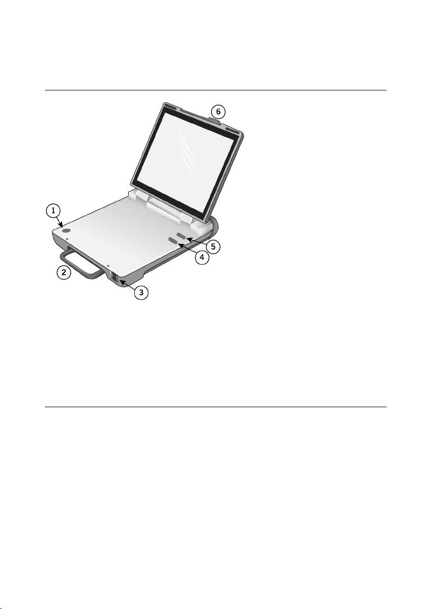
Figure 1. Merlin™ 2 Patient Care System
1. NFC (Near Field Communication) Logo.
2. Fold-away Handle.
3. Two USB Ports. For connection to any USB compatible accessory supported by the
system. Top port is Port 1; bottom port is Port 2.
4. VVI Button. Select this button to reprogram a device to high-output Emergency VVI
settings. See Emergency Operation (page 15).
5. Shock Button. Select this button to display the Shock screen (for ICDs). See
Emergency Operation (page 15).
6. Display Latch.
Page 8
4
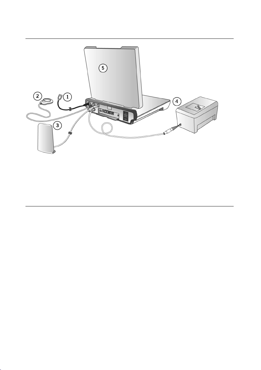
Figure 2. Connections between the Merlin™ 2 PCS, and the Merlin Antenna, Telemetry Wand,
Merlin PSA, and ECG Cables
1. ECG Cable connected to the ECG input port. See Merlin 2 PCS Setup (page 7).
2. Inductive Telemetry Wand connected to the telemetry wand inductive port. See
Merlin 2 PCS Setup (page 7).
3. Merlin Antenna connected to the RF telemetry port. See RF Communication Setup
(page 10).
4. Merlin PSA connected to the PSA port. See Merlin 2 PCS Setup (page 7).
5. Merlin 2 PCS
Page 9
5
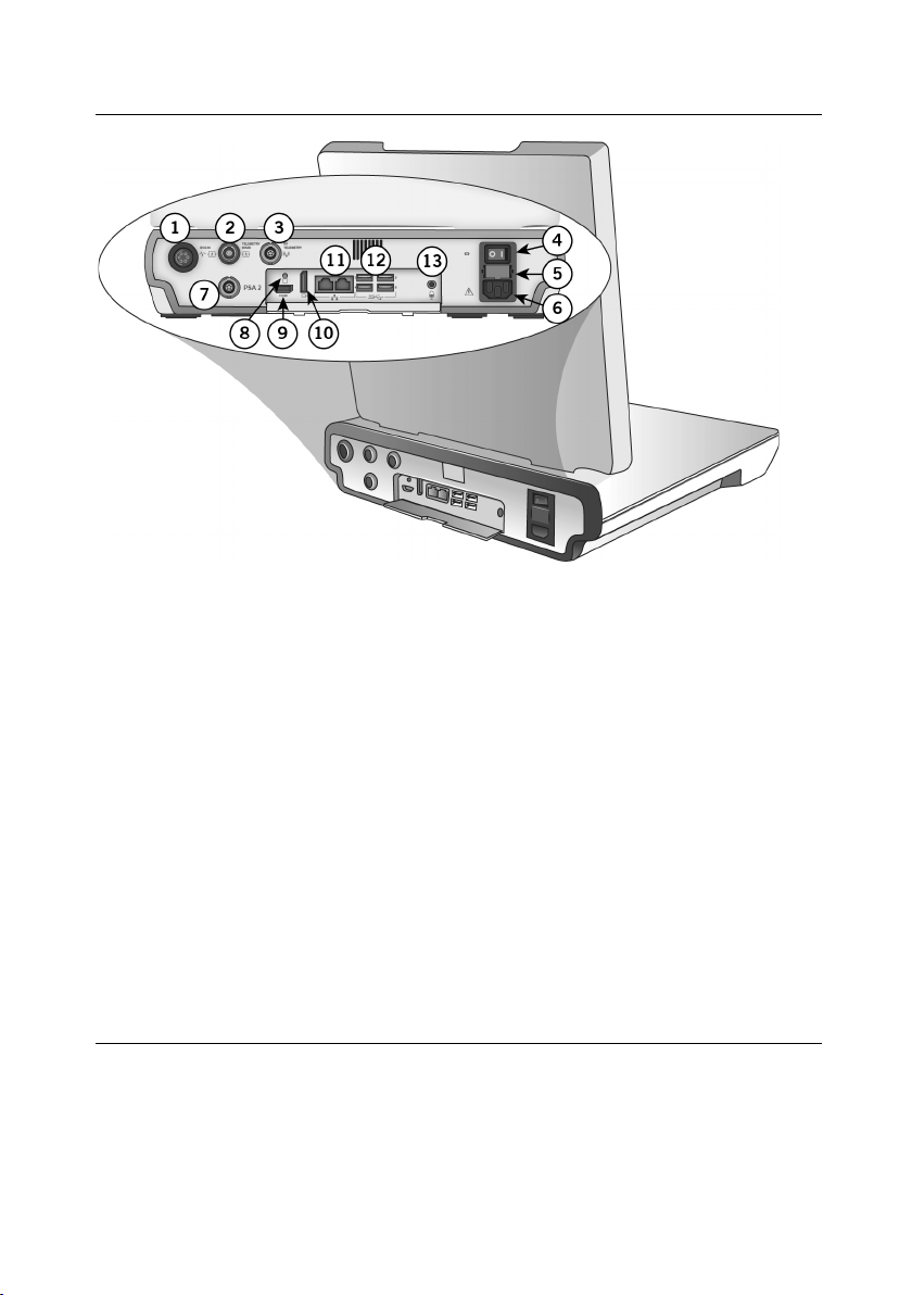
Figure 3. Back side
1. ECG input port. See Merlin™ 2 PCS Setup (page 7).
2. Telemetry wand (inductive) port. For connection to inductive telemetry devices. See
Merlin 2 PCS Setup (page 7).
3. RF telemetry port. For connection to the Merlin™ Antenna. See RF Communication
Setup (page 10).
4. On/Off switch
5. Fuse holder
6. Power receptacle
7. PSA port. For connection to the Merlin PSA Model EX3100. See Merlin 2 PCS Setup
(page 7).
8. Function button. For use by Abbott Medical personnel only.
9. HDMI port. For connection to an external video monitor. See External Device
Connection (page 15).
10. Display port connector (DVI connection)
11. Ethernet ports
12. Four USB ports. For connection to any USB compatible accessory supported by the
system. Top left port is Port 3; bottom left port is Port 4; top right port is Port 5; bottom
right port is Port 6. See External Device Connection (page 15), RF Communication
Setup (page 10), and Bluetooth® Wireless Communication Setup (page 13).
13. Microphone jack input port
Page 10

Page 11
7
Setup Instructions
Merlin™ 2 PCS Setup
WARNING: Do not bring any external control devices, such as a programmer, into the
scanner magnet room (Zone IV). These devices are considered MR Unsafe.
To set up the Merlin™ 2 PCS to communicate with a device that uses inductive telemetry see
Setup for Inductive Telemetry Devices (page 9). To set up the Merlin 2 PCS with a device that
uses RF communication, see RF Communication Setup (page 10). To set up the Merlin 2 PCS
with a device that uses Bluetooth
Communication Setup (page 13).
CAUTION: Do not use if the programmer, cable, or any accessories that connect to the
programmer show visible signs of damage.
1. Place the programmer and accessories on a clean, stable, and well-lit surface. Do not place
any implantable devices on the inside surface of the programmer when the lid is in the open
position and you are attempting to communicate with the Merlin 2 PCS. See the Figure
"Merlin 2 Patient Care System" (page 3).
CAUTION: Ensure the programmer is positioned so the vents are not blocked. Blocking
the vents may lead to overheating, which may cause the programmer to shut down.
2. Plug the power cord into the power receptacle and then into grounded mains outlet.
CAUTION: The Merlin 2 PCS must be connected to a grounded mains outlet with a
hospital-grade cable.
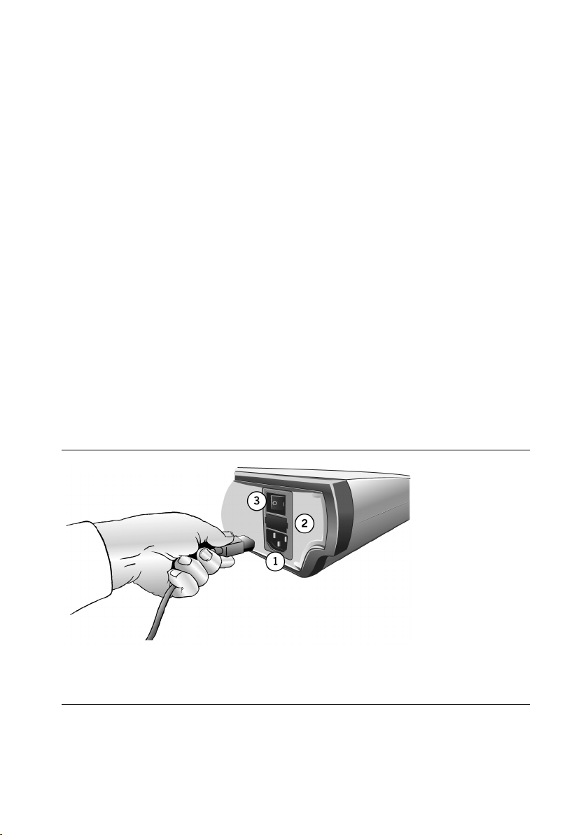
Figure 4. The power receptacle, the fuse holder, and the On/Off switch
®
Low Energy wireless communication, see Bluetooth Wireless
1. Power receptacle
2. Fuse holder
3. On/Off switch
3. You can attach a 5-lead or 3-lead ECG to the Merlin 2 PCS (see below).
With the 5-lead ECG cable, attach up to five ECG electrodes to the patient: Right Arm, Left
Page 12
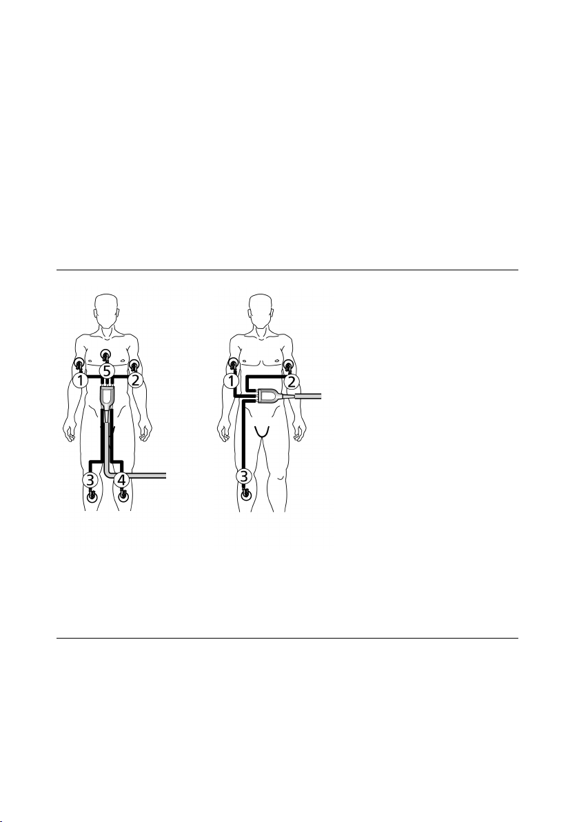
8
Arm, Right Leg, and Left Leg. For the fifth or chest electrode, choose one C location (see
figure below).
With the 3-lead ECG cable, attach electrodes to the Right Arm, Left Arm, and Right Leg (see
figure below).
CAUTION: Use only the ECG cables listed in the Accessories table (page 30) of this
manual to protect the Merlin 2 PCS against possible damage from defibrillator shock.
Do not use the programmer as an ECG monitor or general diagnostic device.
NOTE: With the 3-lead ECG cable, only the Lead I vector is displayed on the Merlin 2 PCS
programmer screen.
4. Attach the ECG leads to the appropriate electrodes.
Figure 5. Color codes and positions of ECG cable connections for 5-lead ECG (left) and 3-lead
ECG (right)
1. R (Red)
2. L (Yellow)
3. N (Black)
4. F (Green)
5. C (White)
CAUTION: Do not allow conductive parts of electrodes or connectors to come into
contact with other conductive parts, including Earth ground.
5. Turn on the power.
6. Open the screen display by releasing the latch.
Use your fingertip or a soft-tip stylus to contact the touchscreen. Do not use pens or pencils
Page 13

9
to contact the touchscreen. The touchscreen has a special coating that can be damaged by
contact with other hard surfaces.
7. On the Merlin™ 2 PCS screen, select the Adjust Display button to configure the ECG
waveform. For more information, select the ? button at the top of the screen when the Adjust
Display window appears.
Figure 6. The Adjust Display button, the Interrogate button, and the Tools Menu
1. Adjust Display button
2. Interrogate button
3. Interrogate monitors button
4. Tools menu
Setup for Inductive Telemetry Devices
1. Place the inductive telemetry wand over the patient's device.
NOTE: For devices that use inductive telemetry, use only the Model 3630W telemetry wand
with the Merlin™ 2 PCS.
2. Select the Interrogate button for pacemakers, ICDs, and CRTs.
3. Use the telemetry strength indicator on the telemetry wand to position the wand over the
device. A single lighted LED indicates telemetry is established. A greater number of lighted
LEDs indicates stronger signal strength.
Setup for Insertable Cardiac Monitors
1. Place the magnet on the patient's device for 3 seconds and remove.
Page 14

10
2. Select the Interrogate Monitors button.
3. The programmer will look for advertising pulses from the Confirm Rx™ Insertable Cardiac
Monitor.
Merlin™ PSA Model EX3100 Setup
Connect the Merlin™ PSA Model EX3100 into the PSA port on the Merlin 2 PCS
For more information on the Merlin PSA Model EX3100, including connection of the patient
cables and patient-cable adapters, refer to the on-screen help on the Merlin 2 PCS and to the
Merlin PSA user's manual.
Figure 7. Merlin™ PSA Model EX3100
1. Functional Status LEDs
2. Pace and Sense LEDs
3. Receptacle for patient cable or patient-cable adapter
4. Connector to Merlin 2 PCS
RF Communication Setup
Some St. Jude Medical implantable devices can communicate with the Merlin™ 2 PCS via radio
frequency (RF), which allows for a greater distance between the device and the Merlin 2 PCS. To
establish RF communication, follow the instructions below.
1. Connect the Merlin™ Antenna to the RF Telemetry port on the back of the Merlin 2 PCS
(see figure below).
NOTE: Connect the Merlin Antenna only to the RF Telemetry port on the back of the
programmer. Do not connect the Merlin Antenna to any other ports.
Page 15

11
Figure 8. Connection between the Merlin™ Antenna and the Merlin™ 2 PCS
1. Merlin Antenna
2. Merlin 2 PCS
2. Place the Merlin Antenna on a flat surface approximately 1 – 2 m (2 – 6 ft) from the
implanted device. The front panel should face the device.
3. Follow steps 1 through 6 in the Merlin 2 PCS Setup (page 7).
Page 16

12
When the Merlin 2 PCS is turned on, the green telemetry strength indicator and blue status
LEDs on the Merlin Antenna will light, indicating the unit is powered and operational.
Figure 9. Merlin™ Antenna, showing the antenna cable, the green telemetry strength indicator
LEDs, and the blue status LEDs
1. Antenna cable
2. Green telemetry strength indicator LEDs
3. Blue status LEDs
When the programmer startup screen appears, the "Ready to Connect to Device" icon
appears under the Tools menu button. See RF Telemetry Icons (page 13).
4. Place the inductive telemetry wand over the patient's device.
5. On the programmer, select the Interrogate button.
After the interrogation is complete, the Merlin™ 2 PCS displays the FastPath™ Summary
Screen. The "Active RF Telemetry connection" icon appears under the Tools menu button.
See RF Telemetry Icons (page 13).
The telemetry strength indicators on the Merlin Antenna indicate RF telemetry
communication between the Merlin Antenna and the device. A single lighted LED indicates
telemetry is established. A greater number of lighted LEDs indicates stronger signal strength.
If necessary, relocate the Merlin Antenna for better communication. See Suboptimal RF
Communication (page 19).
6. Once RF telemetry is established, you may remove the inductive telemetry wand from the
patient.
7. Begin the programming session.
CAUTION: Position the Merlin Antenna at least 20 cm (8 in) away from the patient and
any other devices that might interfere with the Merlin Antenna's operation.
Do not use the Merlin Antenna if its enclosure is damaged.
Page 17

13
Start-Up Screen Icons
Application Icons
RF Telemetry Icons
Table 1. RF telemetry icons for tachycardia devices
Disconnected
Antenna/Not Working
Table 2. RF telemetry icons for bradycardia devices
Start-Up Screen Icons Application Icons
Disconnected
Antenna/Not Working
Ready to connect to
device
Ready to connect to
device
Active RF telemetry
connection
Active RF
telemetry
connection
Inactive RF
telemetry
connection
Inactive RF telemetry
connection
Only wand
telemetry is
available
Bluetooth Wireless Communication Setup
The Merlin™ 2 PCS is Bluetooth® Low Energy wireless compatible. Bluetooth is built into the
Merlin 2 PCS. This allows for communication between the Merlin 2 PCS and an implanted device
that supports Bluetooth Low Energy wireless communication without the need for a dongle.
- Do not put anything between the Merlin 2 PCS and the implanted device. People and
objects may interfere with communication between the Merlin 2 PCS and the device.
- Confirm that the Bluetooth icon is visible on the Merlin 2 PCS Start-up screen.
- Follow the instructions provided on the Start-up screen to begin communication
between the Merlin 2 PCS and an implanted device that supports Bluetooth Low
Energy wireless communication.
- Do not use a Bluetooth dongle.
CAUTION: For optimal Bluetooth Low Energy wireless communication, the
Merlin 2 PCS and St. Jude Medical implantable devices should be within 2 m (6.6 ft) of
each other in normal use. Do not operate a device that may generate interference,
such as a powerful microwave oven, when utilizing Bluetooth Low Energy wireless
communication.
Page 18

14
Network Hardware Connection
You can connect the Merlin™ 2 PCS to a network using the wired ethernet network connection on
the back of the programmer.
Figure 10. Network hardware connection
Shut Down
To power down the Merlin™ 2 PCS:
1. Remove any cables connecting the Merlin 2 PCS to the patient.
2. Move the On/Off switch to the Off position.
The Merlin 2 PCS has a power switch that, when shut off, isolates both conductors of the supply
mains simultaneously.
Page 19

15
Emergency Operation
Figure 11. Emergency buttons (displayed in red)
The console has two red emergency option buttons:
SHOCK. Select this button to display the Shock screen (for ICDs). From this screen, you can
deliver therapy1.
VVI. Select this button to automatically reset the device to predefined high-output settings.2
External Device Connection
The Merlin™ 2 PCS can be connected to three types of external devices: data storage devices,
input devices, and output devices.
NOTE: Not every commercially available external device is guaranteed to operate with the
Merlin 2 PCS. External devices that have been tested and verified to operate are listed in the
Accessories table (page 30).
WARNING: The ports on the Merlin 2 PCS are not isolated. Only connect external
devices that provide proper isolation from the power supply or use the external device
with an isolation transformer. Close the cover after disconnecting the device.
CAUTION: Additional non-medical electrical equipment connected to medical electrical
equipment, which includes equipment connected to the input or output ports, must
comply with the respective IEC or ISO standards. Furthermore, all configurations must
comply with the requirements for medical electrical systems (see IEC 60601-1, Clause
16). Anyone who connects additional equipment to medical electrical equipment is
configuring a medical system and is responsible for the compliance of the system. If in
doubt, contact the Abbott Medical Technical Support department or your local
Abbott Medical representative.
Data Storage Devices
Only external storage devices can be connected to the six USB ports on the Merlin™ 2 PCS. The
devices can be used to save session records, screen captures, and database records that will be
uploaded to patient-tracking software.
Flash drive. A flash drive can be plugged into the Merlin 2 PCS to store data from patient devices.
1
Emergency Shock is not available during a PSA session.
2
Emergency VVI settings for each device are defined in the device's User's Manual.
Page 20

16
Data Export. Data Export applies to data that displays patient information, such as screen
captures, data base records, and pdf reports. Data Export is nominally set to encrypt exported
data (see Personal Identification Number). Session Records and Programmer Logs are
automatically encrypted, and only Abbott Medical personnel can access the data.
You can view Data Export settings in Preferences from the Tools menu To adjust the patient data
export setting, contact Technical Support.
Personal Identification Number (PIN). To export data you must create a Personal Identification
Number. The PIN cannot:
Repeat a number six times in succession, for example 555555
Have consecutive numbers in either ascending or descending order, for example 123456 or
654321
NOTE: Be sure to document the PIN selected. The PIN will be required later to access the
data from the flash drive.
Input Devices
Keyboard. A USB keyboard can be connected to any of the six USB ports for use in conjunction
with the on-screen keyboard.
Mouse. A USB mouse can be connected to any of the six USB ports for use in conjunction with
the on-screen keyboard while in the presence of a patient. Do not use a third-party device that
enables long range control to send remote mouse input, for example over the Internet. For a list of
compatible mice, contact your Abbott Medical representative or Technical Support (page
ECG Input Cable. The ECG Input Cable, supplied by your Abbott Medical Representative, can be
used to display an ECG waveform generated by an external ECG device on the Merlin™ 2 PCS.
See the Accessories table (page
back of the Merlin 2 PCS, and the 3.5 mm mini-plug into the Signal Out port on the external unit.
NOTE: For the best display, select Lead 1 from the ECG Configuration window on the Merlin
2 PCS.
30). Plug the cable's 6-pin connector into the ECG IN port in the
2).
Output Devices
Video Out. The screen display of the Merlin™ 2 PCS can be sent to a video monitor that supports
HDMI capabilities for use while in the presence of a patient. Connect one end of the video cable
into the HDMI port on the rear of the Merlin 2 PCS, and plug the other end into the monitor port.
External Printer. The Merlin 2 PCS can print to some external printers with USB connectors. For
a list of compatible printers, contact Technical Support (page
1. Connect the printer's USB cable to any of the six USB ports on the Merlin 2 PCS.
2. Turn on both the printer and the Merlin 2 PCS.
3. On the Merlin 2 PCS screen, select the Tools button.
4. On the drop-down menu, select the Preferences button, then select the Printer tab.
5. Under "Selected Printer," select the External & PDF button.
6. Close the window and begin the device session.
2).
Page 21

17
Maintenance and Troubleshooting
Maintenance
Merlin™ 2 PCS and Merlin PSA: Service must be performed at the factory or by an authorized
service representative only. The Merlin 2 PCS and its accessories, including the Merlin PSA,
contain no user-serviceable parts.
NOTE: For information on the Merlin PSA maintenance and troubleshooting, see the
Merlin PSA on-screen help.
Cleaning or Disinfecting
To clean or disinfect the exterior of the Merlin™ 2 PCS, Merlin PSA, Merlin Antenna, and ECG
cables:
- Wipe the case with a damp micro-fiber cloth moistened with a mild cleaning solution.
Recommended solutions include: Hand soap or dishwashing soap, isopropyl alcohol
(concentration less than or equal to 90%), chlorine beach, or hydrogen peroxide.
To clean or disinfect the Merlin 2 PCS touch-screen display:
- To clean: Gently wipe the touchscreen with a damp micro-fiber cloth.
- To disinfect: Wipe the touchscreen with a damp micro-fiber cloth moistened with a mild
cleaning solution. Recommended solutions include: Isopropyl alcohol (concentration
less than or equal to 90%), chlorine beach, or hydrogen peroxide.
NOTE: High concentration alcohol is not recommended because it could damage the
touchscreen.
- Do not spray the solution directly onto the touchscreen, and do not allow the cleaning
solution to puddle at the edges of the touchscreen.
WARNING: Keep liquid out of the system's interior, and never spray liquid directly onto
the Merlin 2 PCS or its accessories; otherwise damage may result. If liquid should get
into the system's interior, contact your local Abbott Medical representative. Damage
could occur that is not visible.
CAUTION: Do not modify the Merlin 2 PCS without the authorization of the
manufacturer.
Programmer Self Test/Preventive Maintenance
When you turn on the Merlin™ 2 PCS, the device performs a self-test of the internal hardware
and software. If the test fails, the programmer displays a message explaining the cause of the
failure.
Should the self-test fail, turn off the programmer, wait 30 seconds, and then restart the
programmer. If the self-test fails again, contact Technical Support (page 2).
The programmer and its electronic accessories have been designed with digital circuitry and do
not require calibration.
Telemetry Wand Sterilization
To sterilize the telemetry wand or cables, place the item in a gas-permeable package and sterilize
it in ethylene oxide. Do not exceed 50°C (122°F). After sterilization, allow sufficient time for
complete aeration of ethylene oxide prior to use. This process may be shortened by forced
ventilation. Use biological controls to verify the effectiveness of sterilization.
Page 22

18
WARNING: Do not autoclave, radiation sterilize, or clean ultrasonically or with chemical
solutions.
Do not attempt to sterilize the Merlin™ PSA, the Merlin Antenna, or the Merlin 2 PCS
itself.
NOTE: You can place the Merlin Antenna or the inductive telemetry wand inside a sterile
glove or bag.
Troubleshooting
Start-Up Problems
Possible Causes
Failure to start is most commonly caused by a lack of power.
Solutions Check that the grounded mains outlet is working and the Merlin™ 2 PCS power cord (or
other medical grade power cord) is plugged in properly.
Check that the Merlin 2 PCS power cord (or other medical grade power cord) is plugged into
the back of the Merlin 2 PCS and the Merlin 2 PCS power switch is on.
Check both fuses. Remove the power cord, place a finger under the middle of the fuse
holder, and lift the catch until the fuse holder clicks and pops out. If either fuse is blown,
replace it with the appropriate fuse (see Electrical Specifications (page 21)), plug the unit in,
and turn on the power. If the fuse blows again, contact the Abbott Medical Technical
Support department (page 2).
System Errors
If a software problem occurs, the Merlin™ 2 PCS displays a message indicating that a system
error has occurred and information indicating the origin of the problem. The system displays this
message until you reboot by turning the Merlin 2 PCS off and then on. Before turning the
Merlin 2 PCS off, record the information. All data from the current programming session will be
lost. If the problem persists, contact the Abbott Medical Technical Support department (page 2).
Power Failure
If power to the Merlin™ 2 PCS is lost during a critical telemetry operation (for example, parameter
programming), check the parameter settings and reprogram the device to ensure that the settings
are at the desired values.
Lock-Up
If the screen freezes during normal operation or if the screen blacks out, a lockup may have
occurred.
Possible Causes
Lockup may be caused by a variety of software execution problems, voltage transients, or input
errors.
Solutions
If you suspect a lockup:
1. Remove the telemetry wand from the patient's chest to break telemetry.
2. Re-boot the Merlin™ 2 PCS: Turn off the power. Wait five full seconds. Turn on the power
Page 23

19
again.
3. If the Merlin 2 PCS locks up again, reboot again. If the problem continues, contact your
Abbott Medical representative.
RF Communication Problems
RF Communication problems may be present if you interrogate an RF-enabled implantable device
and:
The Merlin™ 2 PCS does not display the Ready To Connect to Device or Active RF
Telemetry icons (page 13).
Few or no telemetry strength indicators are lit on the Merlin™ Antenna.
The Merlin 2 PCS displays a communication alert.
Make sure that the cable from the Merlin™ Antenna to the Merlin 2 PCS is properly connected,
and the blue status LEDs on the Merlin Antenna are on. Follow the steps in RF Communication
Setup (page 10). If the problem persists, consider the options in the section Suboptimal RF
Communication (page 19) below.
Suboptimal RF Communication
The Merlin™ 2 PCS indicates the quality of the RF communication by the telemetry strength
indicators on both the programmer and the Merlin™ Antenna. Below is a list of possible causes of
suboptimal radio communication:
Possible Causes
The Merlin™ Antenna orientation or location is suboptimal.
People or objects are interfering with the communication between the Merlin Antenna and
the device.
The Merlin Antenna is too far away from the device.
Someone is holding the Merlin Antenna.
Other products nearby are causing electromagnetic interference (EMI).
The Merlin Antenna cable is wound around the Merlin Antenna.
Solutions
Try to optimize RF communication (increase the number of telemetry strength indicator LEDs):
Move or reorient the Merlin™ Antenna slightly.
Make sure that the space between the Merlin Antenna and the device is free from interfering
objects or people.
Move the Merlin Antenna closer to the device.
Make sure that the front of the Merlin Antenna faces the implantable device.
Power off or remove equipment nearby that could cause EMI.
Make sure the Merlin Antenna cable is not wound around the Merlin Antenna.
Do not hold the Merlin Antenna.
If none of the above solutions solve the problem, avoid using RF communication and use the
inductive telemetry wand instead.
BLE Communication Problems
BLE Communication problems may be present if you interrogate a BLE-enabled implantable
device and:
The Merlin™ 2 PCS does not display the Ready To Connect to Device or Active BLE
Page 24

20
Telemetry icons.
The Merlin 2 PCS displays a communication alert.
Follow the steps in Bluetooth® Wireless Communication Setup (page 13). If the problem persists,
consider the options in the section Suboptimal BLE Communication below (page 20).
Suboptimal BLE Communication
Below is a list of possible causes of suboptimal radio communication:
Possible Causes
The Merlin™ 2 PCS orientation or location is suboptimal.
People or objects are interfering with the communication between the Merlin 2 PCS and the
device.
The Merlin 2 PCS is too far away from the device.
Other products nearby are causing electromagnetic interference (EMI).
Solutions
Try to optimize BLE communication:
Move or reorient the Merlin™ 2 PCS slightly.
Make sure that the space between the Merlin 2 PCS and the device is free from interfering
objects or people.
Move the Merlin 2 PCS closer to the device.
Power off or remove equipment nearby that could cause EMI.
If none of the above solutions solve the problem, avoid using BLE communication and use the
inductive telemetry wand instead.
NOTE: If you disable the BLE to use the inductive telemetry wand it may take up to seven
seconds to connect. You cannot deliver emergency shock during that time.
Inductive Communication Problems
If there are any communication problems with the inductive telemetry wand:
Try re-orienting the wand.
Avoid holding the wand.
Try moving the wand farther away from the implanted device.
Move away or turn off the power from equipment that could generate electromagnetic
interference or strong magnetic fields.
Transportation
To move the Merlin™ 2 PCS:
1. Turn off the Merlin 2 PCS.
2. Disconnect the external devices.
3. Disconnect the power cord.
4. Close the display. Make sure that the cover latch is closed.
CAUTION: To avoid breakage, do not lift the Merlin 2 PCS by its display.
Page 25

21
Screen size
38.1 cm (15 in) diagonal
Resolution
VGA (1024 x 768 pixels)
Technical Data
Merlin™ 2 PCS Specifications
The Merlin™ 2 PCS is Class I, Type BF defibrillation-proof medical equipment.
Mechanical
Length 36.3 cm (14.3 in)
Width 34.9 cm (13.75 in)
Height 7.4 cm (2.9 in)
Case material High-impact plastic
Electrical
Input power (mains) 100-240 V~, 50/60 Hz, 3-wire (grounded)
Power supply Medical grade (shielded)
AC power cord 3 m (10 ft)
Current consumption 0.5 / 0.25 A
Fuse
Screen
Display LED
Color 16-bit color
Screen type Touchscreen
5x20 mm, slow-acting, 2.5 A, 250 V~, low-breaking capacity, cartridge
fuse
ECG Cables
5-lead cable 4.14 m (13.6 ft) (Model 3626)
3-lead cable 4.14 m (13.6 ft) (Model EX3001)
ECG input cable 7.62 m (25.0 ft) (Model 3617)
Telemetry Wand
Cord 3.1 m (10.8 ft)
Extension cord 1.22 m (4.0 ft)
Page 26

22
Merlin™ Antenna Specifications
The Merlin™ Antenna Model 3638 is Class I medical equipment3.
Mechanical
Length 5.0 cm (2.0 in)
Width 10.3 cm (4.0 in)
Height 15.3 cm (6.0 in)
Case material High-impact plastic
Electrical
Input power (mains) Powered by Merlin™ 2 PCS
Input voltage 5.0 V
Maximum power consumption 0.5 A
Merlin™ Antenna Cable
Cable to Merlin™ 2 PCS 2.9 m (9.5 ft)
Essential Performance
The Merlin™ 2 PCS communicates with implantable devices (Implantable CardioverterDefibrillators (ICDs), pacemakers, Cardiac Resynchronization Therapy (CRT) devices, and
Implantable Cardiac Monitors (ICMs)). Communication enables operations such as programming,
and the sending and retrieval of data between the Merlin 2 PCS and the implanted device. The
Merlin 2 PCS provides access to the implantable device but does not provide therapy: all therapy
is delivered via the implantable device.
The Merlin 2 PCS provides visual and mechanical interfaces to medical professionals so that they
may assess patient conditions and the functioning of the implantable device.
As per the risk analysis, there have been no unacceptable risks identified in evaluating the clinical
functions of the product and associated risks. The following safety guidelines should be kept
under consideration:
During external interference, such as electromagnetic interference, the programmer will not
undergo any permanent damages that prevents it from communicating with the implantable
device, although the programmer display and communication speed may be affected. The
programmer is able to reestablish and recover display and communication speeds, either
automatically or with manual intervention, once the external interreference is removed.
The programmer is not expected to function if the unit is damaged.
NOTE: For single fault conditions, see Troubleshooting (page 18).
3
The Merlin 2 PCS, Merlin RF antenna, and Merlin PSA comply with IEC 60601-1 + A1: 2012, Ed 3.1, ANSI/AAMI ES60601-1:
2005/A1: 2012 in addition to UL60601-1: 2003, and CAN/CSA - C22.2 NO. 60601-1:14. (Inclusion of ANSI/AAMI ES 606011:2005 does not infer acceptance of the standard by OSHA).
Page 27

23
Data Security
Abbott Medical takes a broad and deep approach to ensuring the safety, security and privacy of
the patient information and data on our devices and systems connecting patients to healthcare
providers and clinics. Patients, clinical staff, and hospital IT staff do not need to configure the
pulse generator or take any special action, for example firewall use, to safeguard patient
information and device data.
The Merlin™ 2 PCS programmer logs security events, for example a failed installation of
programmer software, and stores these log files on disk. These files can then be analyzed by
Abbott Medical personnel during system forensics. They are not meant to be analyzed by the
clinic's information technology personnel.
All safeguards for the devices will be provided throughout the stated warranty period or until a
replacement product is available. In the rare event of a cybersecurity attack on the programmer
that affects its ability to program the pulse generator, implanted device therapy will continue.
Abbott Medical encourages the clinics to allow only authorized healthcare providers to use the
Merlin 2 PCS, for example by requiring badged access to programmer locations. The
cybersecurity bill of materials (CBOM) is available upon request.
Bluetooth Communication
For Bluetooth® Low Energy wireless communication, the Merlin™ 2 PCS and St. Jude Medical
implantable devices should be within 2.5 meters in normal use.
The programmer uses BLE with authentication methods to ensure that the programmer
communicates only with St. Jude Medical authorized products. The integrity and confidentiality of
all data-in-transit during BLE communication is protected by multiple levels of encryption.
Inductive Communication
Inductive Communication is a short-range communication channel that protects patient
information by the proximity of the telemetry wand to the device.
Only authorized healthcare providers should place the inductive wand over the device.
RF Communication
To begin Merlin™ 2 PCS use, the clinician places the programmer's inductive telemetry wand
over the patient's implanted device and initiates communication. The inductive wand has a range
of less than 7 centimeters in normal use. The Merlin 2 PCS then switches to Medical Implant
Communications Service (MICS)-based (RF) telemetry if the implanted device supports it. The RF
telemetry range is less than 2.5 meters in normal use.
St. Jude Medical implantable devices introduced in 2010 and later use proprietary
communications protocol based on magnetic induction and, for certain models, an MICS-based
protocol. This protocol prevents unauthorized device communication and recording and protects
sensitive patient information using:
An authentication algorithm
Data encryption
NOTE: The implanted device authenticates telemetry communication before accepting
changes to programmed therapy.
Electromagnetic Compatibility
The Merlin™ 2 PCS and the Merlin Antenna require special precautions with regard to
Page 28

24
Test
Compliance
Electromagnetic Environment — Guidance
Test
IEC 60601 Test Level (Actual
Level)4
Electromagnetic Environment —
Guidance
electromagnetic compatibility (EMC) and should be used in accordance with the information
provided in this manual.
The Merlin 2 PCS and the Merlin Antenna comply with the requirements of the EMC international
standard IEC 60601-1-2 when used with the cables listed in the Accessories table (page 30).
The Merlin 2 PCS and the Merlin Antenna are intended for use in the electromagnetic
environment specified in the following tables. The user should ensure that they are used in such
an environment.
CAUTION: The Merlin 2 PCS and the Merlin Antenna are intended for use only by
healthcare professionals who must comply with the limits for medical devices
contained in IEC/EN 60601-1-2.
However, the Merlin 2 PCS and the Merlin Antenna may cause radio interference or
may disrupt the operation of nearby equipment. It may be necessary to mitigate this
effect by reorienting or relocating the receiving device or shielding the location.
Table 3. Guidance and manufacturer's declaration — electromagnetic emissions
RF Emission
CISPR 11
Group 1
The Merlin™ 2 PCS and the Merlin Antenna use RF
energy only for its internal function. Therefore, the RF
emissions are very low and are not likely to cause any
interference in nearby electronic equipment.
Class A
The Merlin 2 PCS and the Merlin Antenna are suitable
for use in all establishments other than domestic and
those directly connected to the public low-voltage
power supply network that supplies buildings used for
domestic purposes.
Harmonic emissions
IEC 61000-3-2
Class A
The Merlin 2 PCS and the Merlin Antenna are suitable
for use in all establishments other than domestic and
those directly connected to the public low-voltage
power supply network that supplies buildings used for
domestic purposes.
Voltage
Complies
fluctuations/flicker
emissions IEC
61000-3-3
Table 4. Guidance and manufacturer's declaration — electromagnetic immunity
Electrostatic Discharge
(ESD) IEC 61000-4-2
±8 kV contact
(±8 kV contact)
±15 kV air
Floors should be wood, concrete, or
ceramic tile. If floors are covered
with synthetic material, the relative
humidity should be at least 30%.
(±15 kV air)
4
Figures in parentheses are the immunity compliance levels for each test.
Page 29

25
Test
IEC 60601 Test Level (Actual
Level)4
Electromagnetic Environment —
Guidance
(±2 kV for power supply lines)
Test
IEC 60601
Test Level7
Immunity
Compliance Level
Electromagnetic Environment Guidance8
Table 4. Guidance and manufacturer's declaration — electromagnetic immunity
Electrical fast
transient/burst IEC
61000-4-4
5
Surge
IEC 61000-4-5
Power Frequency
(50/60 Hz) Magnetic
Field, IEC 61000-4-8
Voltage dips, shorts,
interruptions, and
voltage variations on
power supply input
lines
IEC 61000-4-11
±1 kV for input/output lines
(±1 kV for input/output lines)
±2 kV for power supply lines
±1 kV line[s] to line[s]
(±1 kV line[s] to line[s])
±2 kV line[s] to earth
(±2 kV line[s] to earth)
30 A/m
(30 A/m)
<5% U
6[>95% dip in UT] for
T
0.5 cycle
(<5% U
[>95% dip in UT] for
T
0.5 cycle)
[60% dip in UT] for
40% U
T
5 cycles
[60% dip in UT] for
(40% U
T
5 cycles)
70% U
[30% dip in UT] for
T
25 cycles
(70% U
[30% dip in UT] for
T
25 cycles)
<5% UT [>95% dip in UT] for 5 s
(<5% U
[>95% dip in UT] for
T
5 s)
Mains power quality should be that
of a typical commercial or hospital
environment.
Mains power quality should be that
of a typical commercial or hospital
environment.
Power frequency magnetic fields
should be at levels characteristic of
a typical location in a typical
commercial or hospital
environment.
Mains power quality should be that
of a typical commercial or hospital
environment.
If the user of the Merlin™ 2 PCS
requires continued operation during
power mains interruptions, it is
recommended that the
Merlin 2 PCS be powered from an
uninterruptible power supply or a
battery.
Table 5. Guidance and manufacturer's declaration - electromagnetic immunity (conducted RF
and radiated RF)
5
Applies only to the Merlin 2 PCS.
6
UT is the a.c. mains voltage level prior to application of the test level.
7
At 80 MHz and 800 MHz, the separation distance for the higher frequency range applies.
8
These guidelines may not apply in all situations. Electromagnetic propagation is affected by absorption and reflection from
structures, objects, and people.
Page 30

26
Test
IEC 60601
Test Level7
Immunity
Compliance Level
Electromagnetic Environment Guidance8
Recommended separation distance:
80 MHz to 800 MHz
10
800 MHz to 2.7 GHz
d
radio (cellular/cordless) telephones and land mobile radios, amateur radio, AM and FM radio
Table 5. Guidance and manufacturer's declaration - electromagnetic immunity (conducted RF
and radiated RF)
Conducted RF
IEC 61000-4-6
Radiated RF
IEC 61000-4-3
3 Vrms
150 kHz to
80 MHz
3 V/m
80 MHz to
2.7 GHz
(3 Vrms)
[V1=3]
3 V/m
[E1=3]
Portable and mobile RF
communications equipment should be
used no closer to any part of the
Merlin™ 2 PCS, RF Antenna, and
Merlin PSA, including cables, than the
recommended separation distance
9
calculated from the equation
applicable to the frequency of the
transmitter.
where P is the maximum output power
rating of the transmitter in watts (W)
according to the transmitter
manufacturer and
is the
recommended separation distance in
meters (m).
Field strengths from fixed RF
transmitters, as determined by an
electromagnetic site survey*, should
be less than the compliance level in
each frequency range.** Interference
may occur in the vicinity of equipment
marked with the following symbol:
*Electromagnetic site survey- Field strengths from fixed transmitters, such as base stations for
9
These guidelines may not apply in all situations. Electromagnetic propagation is affected by absorption and reflection from
structures, objects, and people.
10
At 80 MHz and 800 MHz, the separation distance for the higher frequency range applies.
Page 31

27
Test
IEC 60601
Test Level7
Immunity
Compliance Level
Electromagnetic Environment Guidance8
broadcast, and TV broadcast cannot be predicted theoretically with accuracy. To assess the
Rated maximum
output power of
transmitter (W)
Recommended separation distance according to frequency of
transmitter (m)
11
150 kHz to 80 MHz
80 MHz to 800
MHz12
800 MHz to 2.7 GHz
0.01
0.12
0.12
0.23
Table 5. Guidance and manufacturer's declaration - electromagnetic immunity (conducted RF
and radiated RF)
electromagnetic environment due to fixed RF transmitters, an electromagnetic site survey should
be considered. If the measured field strength of the location in which the Merlin PSA is used
exceeds the applicable RF compliance level above, the Merlin PSA should be observed to verify
normal operation. If abnormal performance is observed, additional measures may be necessary,
such as re-orienting or relocating the Merlin PSA.
**Over the frequency range of 150 kHz to 80 MHz, field strengths should be less than [V1]V/m.
NOTE: The Merlin 2 PCS is intended for use in an electromagnetic environment in which radiated
RF disturbances are controlled. The user of the Merlin 2 PCS can help prevent electromagnetic
interference by maintaining a minimum distance between portable and mobile RF
communications equipment (transmitters) and the Merlin 2 PCS as recommended in the table
below, according to the maximum output power of the communications equipment. For
transmitters rated at a maximum output power not listed in the table below, the recommended
separation distance (
of the transmitter, where
d) in meters can be estimated using the equation applicable to the frequency
P is the maximum output power rating of the transmitter in watts (W)
according to the transmitter manufacturer.
Table 6. Recommended separation distances between portable and mobile communications
equipment and the Merlin™ 2 PCS
0.1 0.38 0.38 0.73
1.0 1.2 1.2 2.3
10.0 3.8 3.8 7.3
100.0 12 12 23
RF Operating Frequencies
Nearby or hidden equipment emitting strong magnetic fields, such as Radio-Frequency
Identification (RFID) emitters, other medical and radio devices, etc., can interfere with the
Merlin™ 2 PCS inductive and RF communication, even if the other equipment complies with
applicable emission requirements. If interference occurs, you can minimize its effect by
reorienting or relocating the Merlin 2 PCS or by shielding its location.
11
These guidelines may not apply in all situations. Electromagnetic propagation is affected by absorption and reflection from
structures, objects, and people.
12
At 80 MHz and 800 MHz, the separation distance for the higher frequency range applies.
Page 32

28
The operating characteristics of the Merlin 2 PCS and its accessories are as follows:
Inductive Telemetry Wand RF Transmission – Carrier frequency below 100 kHz (inductive telemetry).
Merlin™ Antenna MICS band: 402-405 MHz. The effective radiated power is below the limits as specified in:
- Europe: EN ETSI 301 839
- USA: FCC 47 CFR Part 95; 95.601-95.673 Subpart E, 95.1201-95.1219
The following is applicable to Canada only:
This device may not interfere with stations operating in the 400.150-406.000 MHz band in the
meteorological aids, meteorological-satellite, and earth exploration-satellite services and must
accept any interference received, including interference that may cause undesired operation.
NOTE: Maintain a reasonable distance between other electronic equipment and the
Merlin™ 2 PCS and its accessories.
CAUTION: This transmitter is authorized by rule under the Medical Implant
Communications Service (part 95 of the FCC Rules) and must not cause harmful
interference to stations operating in the 400.150 - 406.000 MHz band in the
Meteorological Aids (that is, transmitters and receivers used to communicate weather
data), the Meteorological Satellite, or the Earth Exploration Satellite Services and must
accept interference that may be caused by such aids, including interference that may
cause undesired operation. This transmitter shall be used only in accordance with the
FCC Rules governing the Medical Implant Communications Service.
Analog and digital voice communications are prohibited. Although this transmitter has
been approved by the Federal Communications Commission, there is no guarantee that
it will not receive interference or that any particular transmission from this transmitter
will be free from interference.
Operation of the Merlin™ Antenna requires that it is subject to the following two
conditions: (1) this device may not cause harmful interference, and (2) this device
must accept any interference, including interference that may cause undesired
operation of the device. Please refer to other parts of this manual for operating
precautions and suggestions on how to minimize any interference to or from other
electronic devices in the area.
Bluetooth Wireless Communication 2.402 to 2.4835 GHz: The effective radiated power is below the limits as specified in:
- Europe: EU EN 300 328
- USA: FCC Part 15 Subpart C paragraph 15.247 FCC 47 CFR Part 95; 95.601-95.673
Subpart E
Quality of Service for Wireless Technology
The Merlin™ 2 PCS communicates with St. Jude Medical implanted devices using inductive, RF,
or BLE telemetry. All telemetry methods operate within worldwide limits for emitted power.
Inductive telemetry operates:
At 64 kilobits/s or lower
Over a short range (less than 7 centimeters in normal use)
Page 33

29
RF telemetry operates:
Using the MICS band (402-405 MHz)
At 200 kilobits/s or lower
Over a short range (less than 2.5 meters in normal use)
Bluetooth
At 2.402 to 2.4835 GHz at 1 megabits/s or lower
Over a short range (within 2 meters in normal use)
During use, the Merlin 2 PCS inductive telemetry wand displays a signal strength indicator to help
clinicians optimize telemetry wand placement. The transmitter automatically monitors and
recovers from most communication errors, including data integrity errors and excessive latency. If
wireless Quality of Service (QoS) is inadequate, the programmer automatically switches to
inductive telemetry.
®
Low Energy wireless communication operates:
Transportation and Handling Conditions
Table 7. Transportation and handling conditions
Minimum Temperature (°C (°F))* -25 (-13)
Maximum Temperature (°C (°F))* 70 (158)
Minimum Humidity (% non-condensing)* 10
Maximum Humidity (% non-condensing)* 90
Minimum Atmospheric Pressure (hPa) 500
Maximum Atmospheric Pressure (hPa) 1060
*Found on box label
Operation and Storage Conditions
Table 8. Operation and storage conditions
Minimum Temperature (°C (°F))* 10 (50)
Maximum Temperature (°C (°F))* 35 (95)
Minimum Humidity (% non-condensing)* 30
Maximum Humidity (% non-condensing)* 75
Minimum Atmospheric Pressure (hPa) 700
Maximum Atmospheric Pressure (hPa) 1060
*Found on Merlin™ 2 PCS label
Disposal
Return the Merlin™ 2 PCS and the Merlin Antenna to Abbott Medical at the end of their operating
lives.
The crossed-out trash can symbol marked on the Merlin 2 PCS and the Merlin Antenna indicates
that Abbott Medical complies with the European Union’s Waste Electrical and Electronic
Page 34

30
Accessory
Model
Number
Ordered
Separately
Intended Use
Symbol
Description
Equipment (WEEE) directive. That directive calls for separate collection and disposal of hazardous
waste from electrical and electronic equipment. Sorting such waste and removing it from other
forms of waste lessens the contribution of potentially toxic substances into municipal disposal
systems and into the larger eco-system.
Accessories
Table 9. Clinical Accessories
5-lead ECG Cable 3626 Yes
3-lead ECG Cable EX3001 Yes
ECG input Cable 3617 Yes
Merlin Antenna 3638 Yes
Merlin PSA EX3100 Yes
Telemetry Wand 3630W No
Provides surface ECG signals for realtime viewing on the Merlin™ 2 PCS
Provides surface ECG signals for realtime viewing on the Merlin 2 PCS
Provides surface ECG signals for realtime viewing on the Merlin 2 PCS
Provides wireless radio frequency
communication between the
programmer and the device during a
programmer session
Assess the pacing and sensing
performance of the lead system prior
to implantable medical device
implantation, or during invasive lead
system troubleshooting
Provides inductive communication
between the Merlin 2 PCS and the
device during a programmer session
Symbols
For information on symbols pertaining to the Merlin™ PSA Model EX3100 and its accessories,
refer to the Merlin PSA on-screen help.
The symbols below and harmonized symbols may be found on the product or product label. For
harmonized symbols, refer to the Universal Symbols Glossary at https://medical.abbott/manuals.
Part number
Page 35

31
Symbol
Description
European conformity, affixed according to the relevant provisions of
European Council Regulation 2017/745 (NB 2797) and RE directive
2014/53/EU Annex II. Hereby, Abbott Medical declares that this device
complies with the relevant provisions of this regulation and directives.
The full text of the European Union RE directive 2014/53/EU declaration of
conformity is available at the following internet address:
sjmglobal.com/euconformity.
This product operates between 9 and 200 kHz with an H-field strength of
less than 25 dBµA/m at 10 m.
Affixed to this device in accordance with European Council Directives
2002/96/EC.
These directives call for separate collection and disposal of electrical and
electronic equipment. Sorting such waste and removing it from other
forms of waste lessens the contribution of potentially toxic substances into
municipal disposal systems and into the larger ecosystem.
Return the device to Abbott Medical at the end of its operating life.
Display Out port
ECG Cable
ECG IN cable port
Ethernet port (non-functional)
Flash drive
Fuse
Merlin 2 Patient Care System Model MER3700
An accessory to Merlin 2 Patient Care System Model MER3700
Page 36

32
Symbol
Description
Off
On
Pacing system analyzer port
Power cord
Follow instructions for use on this website
Malaysian Communication and Multimedia Commission (MCMC)
certification mark for products meeting applicable MCMC Technical Codes
Australian Communications and Media Authority (ACMA) and New
Zealand Radio Spectrum Management (RSM) Regulatory Compliance
Mark (RCM)
This equipment is certified for type certification pursuant of Article 38-24
of the Japan Radio Law
Korea Certification mark for electrical devices
FCC ID: XXXX TBD
RF Telemetry port
Telemetry wand
Connect to the RF Telemetry port on the Merlin 2 PCS
Conforms to
AAMI Std ES60601-1
IEC Std 60601-1-11
Certified to CAN/CSA std C22.2 No. 60601-1
Made in USA
Unique device identification number
FCC Identification Number
Page 37

33
Symbol
Description
IC: XXXX-XXX TBD
Industry Canada certification
USB port
Product literature
Manufacturing facility
Importer
Wi-Fi port
Medical Device
Page 38

Page 39

Page 40

St. Jude Medical
St. Jude Medical
St. Jude Medical Puerto Rico LLC
St. Jude Medical Operations (M) Sdn. Bhd.
2021-03
Cardiac Rhythm
Management Division
15900 Valley View Court
Sylmar, CA 91342 USA
+1 818 362 6822
Lot A Interior - #2 Rd Km. 67.5
Santana Industrial Park
Arecibo, PR 00612
USA
ARTEN100167142 A
Coordination Center BVBA
The Corporate Village
Da Vincilaan 11 Box F1
1935 Zaventem
Belgium
+32 2 774 68 11
Plot 102, Lebuhraya Kampung Jawa,
Bayan Lepas Industrial Zone
11900 Penang
Malaysia
 Loading...