

Page 1

EDR4 1200 04/03
1
Toll free helpline
Please have your serial number and
model name available before calling.
Australia 1800 638 234
New Zealand 0800 653 667
United Kingdom 0800 073 0112
www.merlingo.com
Installation instructions
remote control openers
security at your fingertips
G950
residential gate opener for swing gates
Page 2
EDR4 1200 04/03
2
Index
Important safety instructions for
installation
WARNING Incorrect installation can lead to severe injury. Follow all installation instructions.
Merlin Garage Openers Limited does not accept responsibility for damage or injury resulting from installing this opener.
Before installing the drive remove or disable any equipment, such as locks, that is not
needed for powered operation.
Before installing the drive check that the gate is in good mechanical condition and that it
opens and closes properly.
Do not use force sensitivity adjustments to compensate for a binding or sticking gate.
Excessive force may damage the gate.
Install any fixed control, wired or wireless, within sight of the gate but away from moving
parts and at a height of more than 1.5 m.
After installation, ensure that the mechanism is properly adjusted and that the drive stops
when the gate contacts an obstruction.
Site requirements
Gate
This opener is designed for residential swing gates up to 3 metres wide and less than 230
kg.
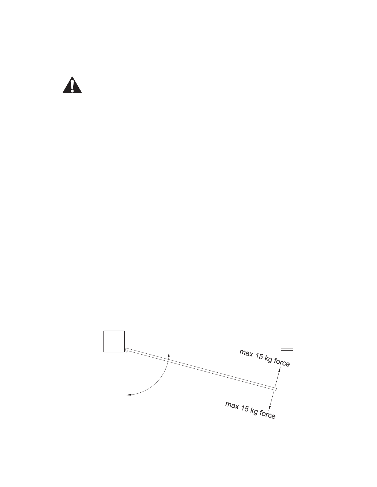
Using a spring balance, check that less than 15 kg force (150N) is required to manually
move the gate through its full range of movement. The gate should operate smoothly, opening and closing without sticking. Hinges should not have excessive play or friction.
Check the mounting points and hinges for strength and stiffness. Reinforce if necessary.
Page 3
EDR4 1200 04/03
3
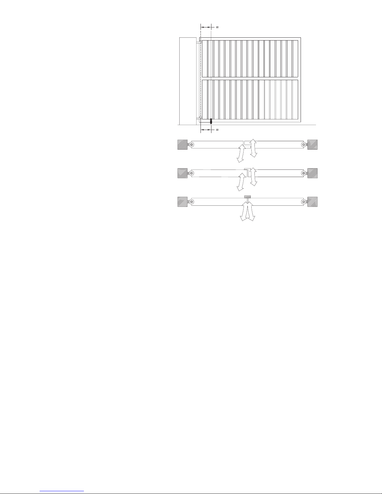
Level and square the gate
The gate hinge pivot points should be perfectly parallel to a plumb line.
When closed, the gate leaves should line
up evenly and not bind against each other.
The leaves should not be damaged or bent.
Gate stops
It is recommended that any of the following are used:
- Overlapping gate leaves
- A tag on one gate
- Gate-stops at the limit of each leaf’s travel
Power supply
If the opener is to be mains-powered, then
the 3-pin power plug should be shielded
from the effects of weather.
The product is tested as a unit for electrical safety compliance and if the plug is cut
off for hard-wiring, then the electrical safety
of the unit becomes the responsibility of the installing electrician.
An isolating switch is recommended, but all mains wiring should be in accordance with local
regulations, for example AS/NZS 3000:2000.
Wiring
All wiring must be arranged to prevent water entering the controller enclosure.
Do not wire mains voltages and low voltage control wires in the same conduit.
Low voltage cable sizes
Voltage will drop along low voltage cables over long distances. It is recommended to use
cable with conductors of the following minimum cross sectional areas. The table lists lengths
for twin-core cable, from the supply to the load.
For an optional solar panel, consider the total length from the panel to the controller board,
through to the battery.
Follow the table for minimum recommended conductor sizes for given lengths for each
power option.
Cable length From 10 W solar panel From controller to each motor
to 12 V battery 12 V @ 4 A max
(for max 2% volt drop) (for max 5% volt drop)
3 m 1.0 mm
2
1.5 mm
2
5 m 1.0 mm
2
2.5 mm
2
10 m 1.0 mm
2
4.0 mm
2
15 m 1.0 mm
2
6.0 mm
2
20 m 1.0 mm
2
10 mm
2
25 m 1.5 mm
2
10 mm
2
30 m 1.5 mm
2
16 mm
Page 4
EDR4 1200 04/03
4
Battery power with trickle charging
Due to the high cost of long runs of heavy cable, it may be more economic in some installations to operate the gates from a larger battery, which is charged from a remotely located
trickle charger.
For example, a 12V 500 mA plug pack can be located at the house, with only light gauge
wiring to the gate, controller, and battery some distance away. Due to varying gate loads
and duty cycles for each installation, this is a guide only.
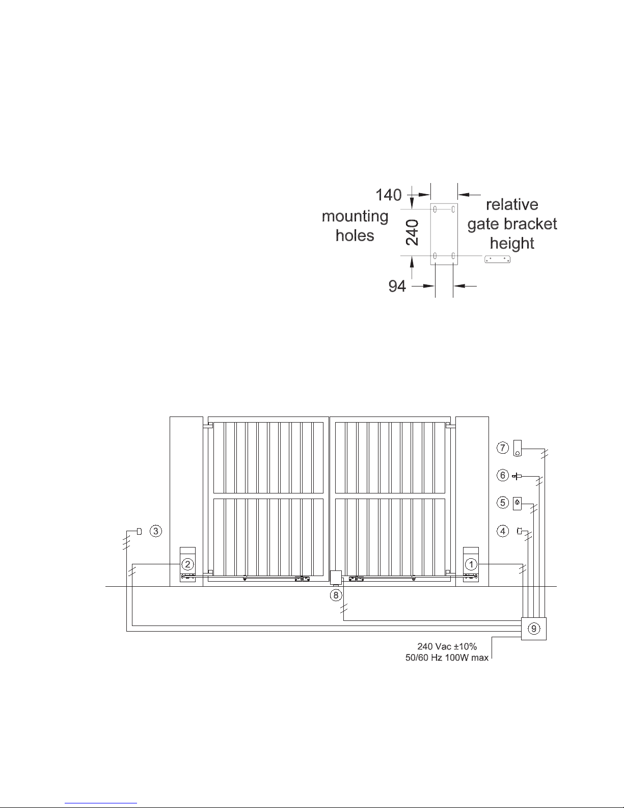
Mounting the operators to the gate posts
There should not be any visible flexing of
the mounting points under load.
To spread the load, all mounting holes
should be used.
Mount the opener 50 mm from the inside
edge of the gate post.
Use fasteners of at least 10 mm diameter
x 75 mm length.
Note the top face of the gate bracket aligns with the centres of the bottom mounting holes
of the opener.
Optional control box (standard in NZ)
Locate this in any convenient weather-protected position. All mounting holes and cable
entry or exits must be suitably sealed to prevent water from entering the enclosure. Cables
should exit the control box from below only.
1 Right hand opener (slave)
2 Left hand opener (slave)
3 Receiving IR sensor (3-wire)
4 Transmitting IR sensor (2-wire)
5 Push-button (must be rated suitably for the weather conditions)
Page 5
EDR4 1200 04/03
5
6 Keyed switch (must be rated suitably for the weather conditions)
7 Keypad (wireless control; optionally wired power supply)
8 Solenoid lock or latch (avail. for horizontal or vertical applications)
9 Enclosure for controller, receiver, and optional backup battery
NOTE The Merlin M122 wired push-button and M128 wireless push-button are
not waterproof, and are only rated for interior use.
The Merlin KWF1 keyed switch is not intended for use fully exposed to weather in
gate installations.
Merlin does not warranty any items used outside their published ratings or intended
use.
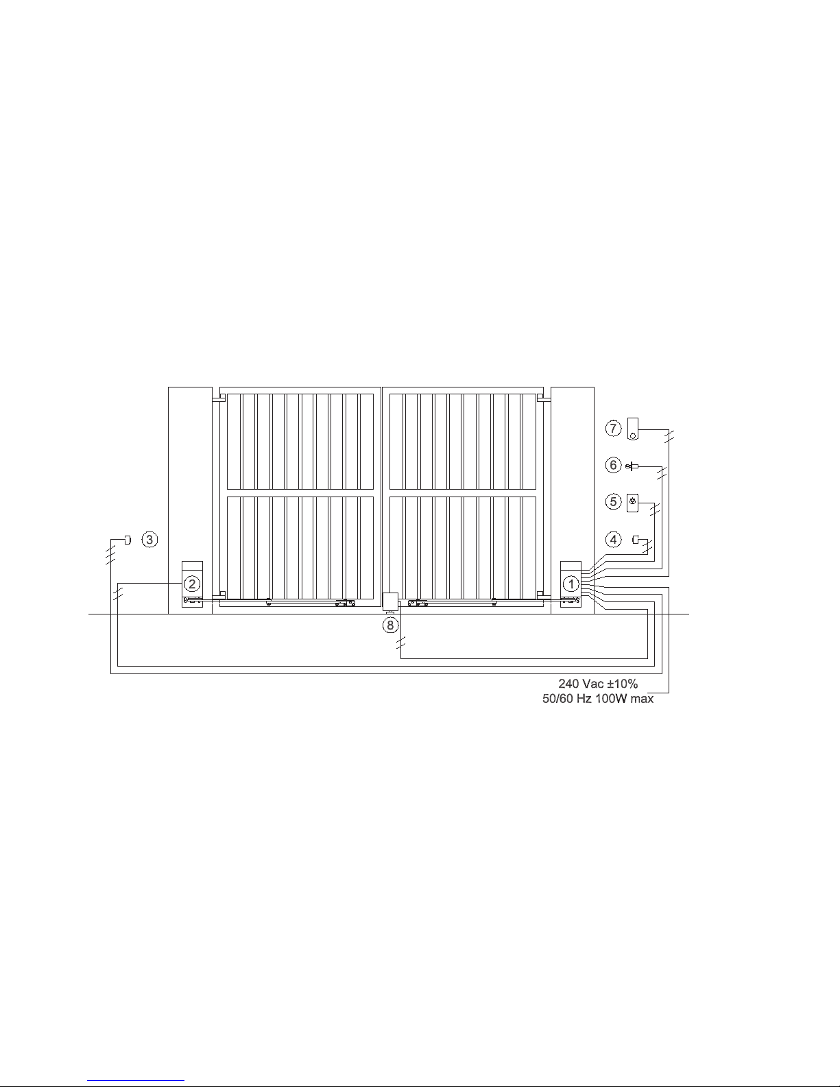
Master and slave operators (Australia only)
The Master operator has the controller board, transformer and optional back-up battery
inside it. Locate it on the side of the gate nearer to the power supply.
The Slave operator connects to the master by a two-core conductor carrying 12V.
1 Right hand opener (shown as master, but depends on site)
2 Left hand opener (shown as slave, but depends on site)
3 Receiving IR sensor (3-wire, Merlin M103)
4 Transmitting IR sensor (2-wire, Merlin M103)
5 Push-button (must be rated suitably for the weather conditions)
6 Keyed switch (must be rated suitably for the weather conditions)
7 Keypad (Merlin M840, wireless, optionally with wired power supply)
8 Solenoid lock or latch (avail. for horizontal or vertical applications)
NOTE The Merlin M122 wired push-button and M128 wireless push-button are
not waterproof, and are only rated for interior use.
The Merlin KWF1 keyed switch is not intended for use fully exposed to weather in
gate installations.
Merlin does not warranty any items used outside their published ratings or intended
use.
Page 6

EDR4 1200 04/03
6
Installation clearances
Standard side-room vs. Restricted side-room
The standard side room requirement is
550 mm. If less than this is available, it
is possible to shorten the secondary
arm (the one that attaches to the gate).
Do not shorten it to less than 350 mm.
Take care that the attachment point
between the gate and the secondary
arm does not foul on the output shaft.
A certain amount of trial and error is
involved in selecting the optimum position for the gate bracket. See the following sketches as a guide.
Standard
The gate hinge should be no more than 200 mm forward of the mounting face of the drive.
In the example shown, reducing the length of the secondary arm reduces sideroom considerably. Note however that the leverage applied by the opener on the gate can change
dramatically in the last part of the opening cycle. Ensuring the angle between the arms is
always greater than 40 degrees is recommended.
When the arms are fully extended, the angle between them should not be more than 175
degrees.
For reduced sideroom
Page 7

EDR4 1200 04/03
7
Side mounting
This is useful where the
gate must open further
than 90 degrees, or where
the gate must open outwards. Contact Merlin for
side-mounting covers.
Out-swinging gates
This also requires side-mounting covers. It may be necessary to fabricate longer primary
arms for some installations.
Attaching the gate bracket to the leaf
The gate bracket connects the secondary arm to the gate leaf.
Position it after following the diagrams above. The primary and secondary arms must never
be less than 5 degrees off a straight line from each other.
Choose a point which is less likely to deflect under load.
If necessary weld support around the area where the bracket must be positioned.
Out-swinging gate at front of
post with sidemounted opener
Out-swinging gate at rear of
post with sidemounted opener
Page 8

EDR4 1200 04/03
8
Connecting the board wiring
NOTE When powering any accessories from the board, (for example: gate
latches, additional receivers, keypads, PE beams) ensure the power supply has
adequate capacity. Measure the voltage at DC IN under full motor load. If it falls
below 9 V dc then the board, receiver, and some accessories, may not function
correctly. In this instance, remove accessories, upgrade the power supply, or
provide additional power supplies directly to each accessory.
Battery polarity LED
(shines if wires have
reversed polarity)
Merlin M001 coaxial antenna
connector (for MCX plug only)
Standard antenna wire
(must remove if using M001)
antenna wire
27/40 MHz only
(must remove if
using 433 MHz)
Motor 1 OP
(brown wire)
Motor 1 CL
(blue wire)
Motor 2 OP
(blue wire)
Motor 2 CL
(brown wire)
Latch -
Latch +
dc out at supply
voltage and current
for 2 sec at start of
opening cycle
PE Cell (relay
contact type)
Open =
obstructed.
Closed = OK.
(must use
jumper wire if no
PE cell is fitted)
DC in +
DC in –
typ 12 V
min 10 V
max 20 V
Push-button
(momentary
contact only)
Battery +
Battery -
Page 9

EDR4 1200 04/03
9
Connecting the motor wiring
Motor 1 is the left hand motor when facing out of the driveway. If Motor 1 is on the right
hand side, reverse the polarity of the motor wires.
If a single opener is fitted, use the Motor 1 terminals. If a single opener is fitted on the right
hand side, reverse the polarity of the motor wires.
If a motor pushes a gate outwards, reverse the polarity of the motor wires.
Setting the motor limit cams
Do not fully fit the primary arm to the drive before setting the limits. Leave the bolt loose so
that the drive does not engage with the arm. This will prevent possible injury or damage
before the limits are correctly set.
Close the gates
Operate the motors until their output shafts are in the correct position to engage with their
primary arms of closed gates. Loosen the limit cam cap-screw.
Page 10

EDR4 1200 04/03
10
Left hand motor: rotate the bottom cam anticlockwise until it actuates the switch.
Right hand motor: rotate the top cam clockwise until it actuates the switch.
Re-tighten the limit cam cap-screw.
Open the gates
Operate the motors until their output shafts are in the correct position to engage with their
primary arms. Loosen the limit cam cap-screw.
Left hand motor: rotate the top cam clockwise until it actuates the switch.
Right hand motor: rotate the bottom cam anticlockwise until it actuates the switch.
Re-tighten the limit cam cap-screw.
Board adjustments
Sensitivity
Allow for the effect of weather. Wind or water will make the gates more difficult to move. If
the sensitivity is set to react to extremely light obstructions then the gates may fail to open
or close fully. After adjustment, check that the force on an obstruction at the far end of the
gate leaf does not exceed 150N (15 kg). Use a spring balance.
Travel time
Set the timer to allow 3 – 5 seconds more than the normal travel time. This compensates
for any possible slow-down due to unusual loads and will allow the gates to fully open or
close.
The yellow LED will stay on while the timer is active.
Auto-close
The jumper must be moved to the AUTO CLOSE position.
Turn the timer control clockwise to increase the delay, from a minimum of 6 seconds up to
a maximum of around 210 seconds.
Consider the use of the multi-user option (see below).
NOTE Non-contact sensor beams must be fitted when using auto-close.
Multi-user option
Move the jumper to the MU position. In this position every command will open the gate. The
only way to close the gate is to wait for the auto-close timer. The advantage of this mode is
that an opening gate with a car travelling through it can not be caught by someone pressing
a remote control to close the gate.
NOTE Autoclose must also be enabled, otherwise the gates can not be closed.
Motor 1 open delay
Essential when using gate tabs or overlapping leaves. To prevent clashing of the gate leaves
when opening, increase the Motor 1 open delay by turning the adjuster clockwise.
Motor 2 close delay
Essential when using gate tabs or overlapping leaves. To prevent clashing of the gate leaves
when closing, increase the Motor 2 close delay by turning the adjuster clockwise.
Page 11

EDR4 1200 04/03
11
Receiver setup
Mode jumper
This jumper must be removed. If it is not removed then the remote control will only operate
the gate once for every two button presses. This jumper enables the latching output on the
receiver card.
Learning remotes
The receiver can learn up to 20 remotes. After 20 remotes, the 20th will be overwritten.
Only one button per remote can operate the receiver.
To learn a remote, press and hold the LEARN button until the receiver status LED goes out.
Press the desired button on the remote control and hold till the status LED flickers. Press it
again to confirm.
Remote Transmitter Learning (RTL)
This option allows a user to add remotes without accessing the receiver card.
It does not allow the deletion of remotes. After 20 remotes, the 20th will be over-written.
If RTL is enabled the receiver status LED will double-flash in the standby state. If RTL is
disabled the receiver status LED will single-flash in the standby state.
To change state, hold the LEARN button down for three seconds as the power is reset.
Check the receiver status LED flashes to confirm the state change.
Merlin recommends enabling this option. Check for a double-flash on the receiver status
LED at standby.
Deleting remotes
All remotes can be deleted by pressing and holding the LEARN button for 11 seconds, until
the receiver status LED stops fast-flashing. This resets the receiver back to its default
settings. Check you still have the desired RTL state.
Common Access installations
To allow unlimited numbers of common access users, the M832C or M834C remote controls are required. These have a DIP switch code block that sets a fixed code for the main
button on the M832C or on two buttons of the four on the M834C. The remaining buttons
are high-security code-hopping.
The M834C is useful for separate entry and exit gates.
Common access remotes are only available in the full-sized remote controls.
Adding an external antenna
Only connect a Merlin M001 external antenna with MCX co-axial connector to the receiver
card. This antenna, cable and connector is tuned to give the best performance.
Before attaching the co-axial connector, snip the simple wire antenna from the receiver
card so that only one antenna is active.
The ground plane of the M001 greatly improves the antenna’s performance. An alternative
is to mount the antenna through a metal plate that is at least as large as the ground plane’s
length. For optimum performance any ground plane should make good electrical contact
with the metal boss of the M001 antenna.
Contact Merlin for M002 (10m) or M003 (3m) antenna extension cables if additional distance is required between the controller and the antenna.
Page 12

EDR4 1200 04/03
12
Setting up the board
NOTE Reverse motor wires if open and close LEDs don’t match gate travel.
MANUAL /
AUTOCLOSE
Jumper
(safety beams
must be fitted)
Motor 1 open delay
(max = clockwise)
2 – 5 sec
MODE jumper
(must be removed)
Motor 1
Sensitivity
(max = clockwise)
Test button
(press to
operate gate)
Motor 2
Sensitivity
(max = clockwise)
MU / NORM jumper
(MU = every command
opens the gate
NORM = open / stop / close)
(Requires Autoclose)
Status LEDs
(red = closed
green = open)
LEARN button
(hold 1s, release
press remote 1s
press remote 1s)
(hold 3 sec at
power-up to change
RTL state)
(hold 11 sec to
delete all remotes)
Receiver status LED
(double-flash = RTL
single-flash = normal)
Motor 2 close delay
(max = clockwise)
2 – 5 sec
Travel time
(min = clockwise)
must allow extra
8 seconds
Travel timer LED
(ON = timer ON)
Auto-close timer
(min = clockwise)
6 – 210 sec
if jumper ON
Page 13

EDR4 1200 04/03
13
Optional extras
Keypad
The Merlin M840 keypad can accept a hardwired power supply to overcome the need for
replacement batteries. See the keypad documentation for full details, but any supply with
50 mA at 10 – 24 V ac or dc is suitable. Control of the gate opener is wireless using high
security code-hopping RF.
Solenoid lock (latch)
See the lock’s documentation for installation details.
Merlin can supply either horizontal or vertically actuating locks.
PhotoElectric (PE) sensor beams
You can fit any sensor beams with relay contact outputs that can be configured as open
contacts when obstructed and closed contacts when OK.
Merlin M103 sensor beams require three wires for the receiver beam and two wires for the
transmitter beam.
NOTE Sensor beams must be fitted when Autoclose is enabled.
Battery backup
A trickle charging circuit is included in the controller board. Connect the 12 V 2 Ah battery
to the terminals. A dc supply from a transformer will charge the battery.
Battery power
If a 9Ah battery is fitted, then in some installations it may be possible to charge the battery
from a small (12 V 500 mA, for example) plug pack. Note that the duty cycle of the gates,
and the load presented by the gates, will affect the viability of this option, and the size of
power pack required.
Solar power
Contact Merlin for the correct board, battery and panel. However, if it is necessary to modify
an existing board, remove the resistor shown and connect as follows.
In some applications a larger battery, and possibly a larger
solar panel, will be required. It depends on:
the duty cycle of the gates; the type of
receiver fitted; the hours of sunlight; and
the number and type of accessories fit-
ted.
In many instances a 9Ah battery
is required. A low power 40
MHz receiver may also be required in order to use the standard 10W solar panel.
If an alternative panel is sourced, and it is self
regulating, then the additional 6A diode
(shown left) is not necessary.
Page 14

EDR4 1200 04/03
14
Troubleshooting
Remote controls will not function while gate is moving
The total load on the power supply may be exceeding its capacity. Measure the voltage into
the board. If less than 9V dc when the motors are under load, then a higher capacity power
supply must be fitted, or some accessories removed, or separate power supplies provided
for the accessories.
Gate will not open or close
The gate should operate smoothly, opening and closing without sticking or requiring undue
force. Release the gate from the opener and check that it is possible to move the gate
freely by hand through the full range of the opening.
There may be a power failure. Plug another appliance into the power point to check. Opener
may require service. If solar powered, the battery may not be fully recharging.
SOLUTION: Operate the gate manually. Phone an installer for service.
Gate will open but not close
If a sensor beam is fitted then it may be obstructed or misaligned. The gate mechanism may
have broken, presenting an abnormal load, causing the safety system to activate.
SOLUTION: Look for anything blocking the beam sensor. Is the beam aligned correctly?
Release the manual release and check the gate can be operated easily by hand. Have your
gate repaired or serviced if it is heavy to move by hand.
Transmitter range is less than normal
Your transmitter battery may be going flat. If you have an external antenna then the wire
may be damaged.
SOLUTION: Replace the transmitter battery. Phone for service if the antenna wire is damaged
Transmitter doesn’t work some times
There may be occasional radio interference in your area. Your transmitter battery may be
going flat.
SOLUTION: Check for nearby baby monitors, remote control toys, cordless phones. Replace the transmitter battery.
Radio interference
Gate remote controls are required to operate in shared radio frequency bands. Regulations
permit other users to continuously operate higher powered devices such as baby monitors
or wireless headphones in these shared bands. These devices may cause radio interference that reduces the performance of the remote control. Switch off interfering devices if
possible. Remote controls and receivers that operate on alternative frequencies are available at additional cost.
Transmitter doesn’t work at all
Your transmitter battery may be flat. SOLUTION: Replace the transmitter battery.
Page 15

EDR4 1200 04/03
15
Maintenance
In an area where ant or insect infestation is likely, regularly spray around the opener and
any electrical installation with insecticide.
In normal conditions it is not expected that any additional lubrication or service is required.
Keep the path of the gate free from debris and foliage.
Page 16

EDR4 1200 04/03
16
Specifications
Mains power required 220 V to 240 V ac, 50 Hz, earthed
Extra Low Voltage supply (optional) 4 A per motor at 12 V dc
Rated load max 300 N (approx 30 kg force) at right an-
gles to the end of the primary arm
Stand-by power consumption max 0.5 W
Operating power consumption max 50 W per motor
Gate length max 3 m
Gate weight max 230 kg
Operating time typ 10 – 15 seconds (increases with load)
Opening angle (standard) max 110 degrees
Opening angle (with side mount kit) max 130 degrees
Replacement board fuse 0.5 A (32 mm x 6.35 dia)
Replacement motor fuse 10 A (32 mm x 6.35 dia)
Replacement remote control battery Depends on model, either 4LR44 (6V) or
CR2025 (3V coin cell)
Gate stops optional but recommended
Gate solenoid lock optional but recommended
NOTE Any additions or alterations outside of these specifications may void the
product’s warranty
 Loading...