

Page 1
Installation Instructions
G940 Harmonic swing gate operator (discontinued)
Rev 01, May 03 © Merlin Garage Openers Limited Page 1 of 3
The Merlin G940 Harmonic swing gate operators are ruggedly
built and versatile units. The G940 is a compact unit suited for
small to medium sized gates. Suitable for single or double
swing gates and provide years of reliable service.
Specs
Power options 230v. ac, 12v. dc, solar
Current 3 amp per motor
Maximum duty cycle 100%
Travel time 10-14 seconds
Maximum gate weight / length 150Kg / 3 meters
Maximum opening angle 110 deg
Gate stops required optional / recommended
Gate lock required optional
Standard features
Independent limit controls
Auto close, adjustable 6-210 seconds
Adjustable force sensitivity
Two speed motor option
Leaf delay for electric locks or clash bars.
Multi-use function.
Optional Accessories
Battery back up
Solar power option
Safety beam sensors
Electric lock
Intercom
Keypad entry.
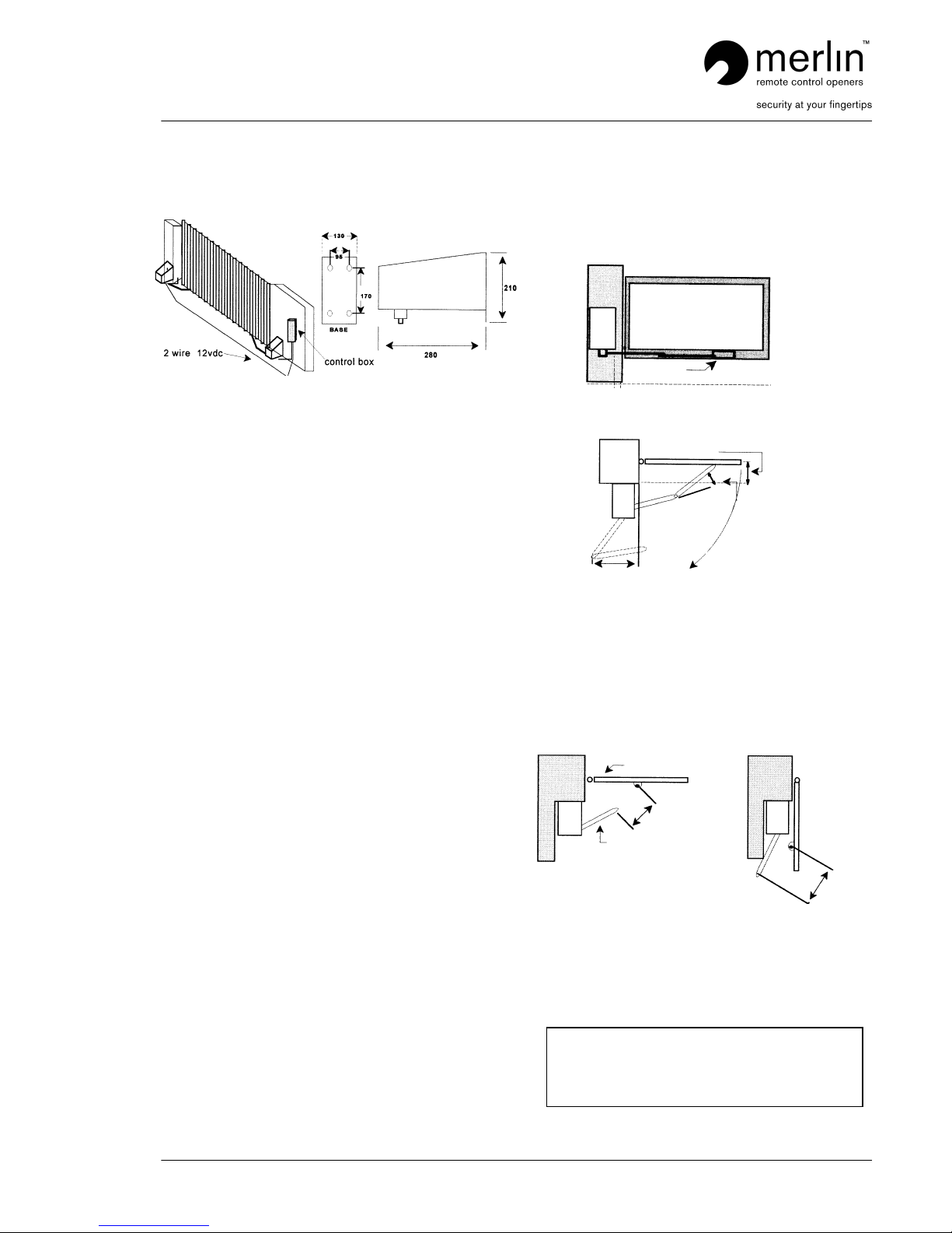
Step 1
Fasten the motor securely to the gatepost, and the gate
bracket to the gate as shown in fig A & B.
Fig A
Gate bracket
50mm
Fig B
Gate in closed position
200mm max
5 degrees min
515mm std
350mm min.
Restricted side room installation
Where there is restricted side room (between 515mm &
350mm) the secondary arm must be cut to suit.
Move the primary arm into a position suitable for the gate in
the closed position. Measure as in Fig C while temporarily
clamping the bracket to the gate.
Fig C Fig D
Gate
Primary arm
Move the gate to the open position as in Fig D, and remeasure. The correct bracket position and secondary arm
length will be when the distance is equal for the open and
closed.
Caution
Ensure that the secondary arm dose not interfere with
the primary arm.
Minimum angle between the primary & secondary arms,
in the open position should be no less than 40degrees.
Page 2
Installation Instructions
G940 Harmonic swing gate operator (discontinued)
Rev 01, May 03 © Merlin Garage Openers Limited Page 2 of 3
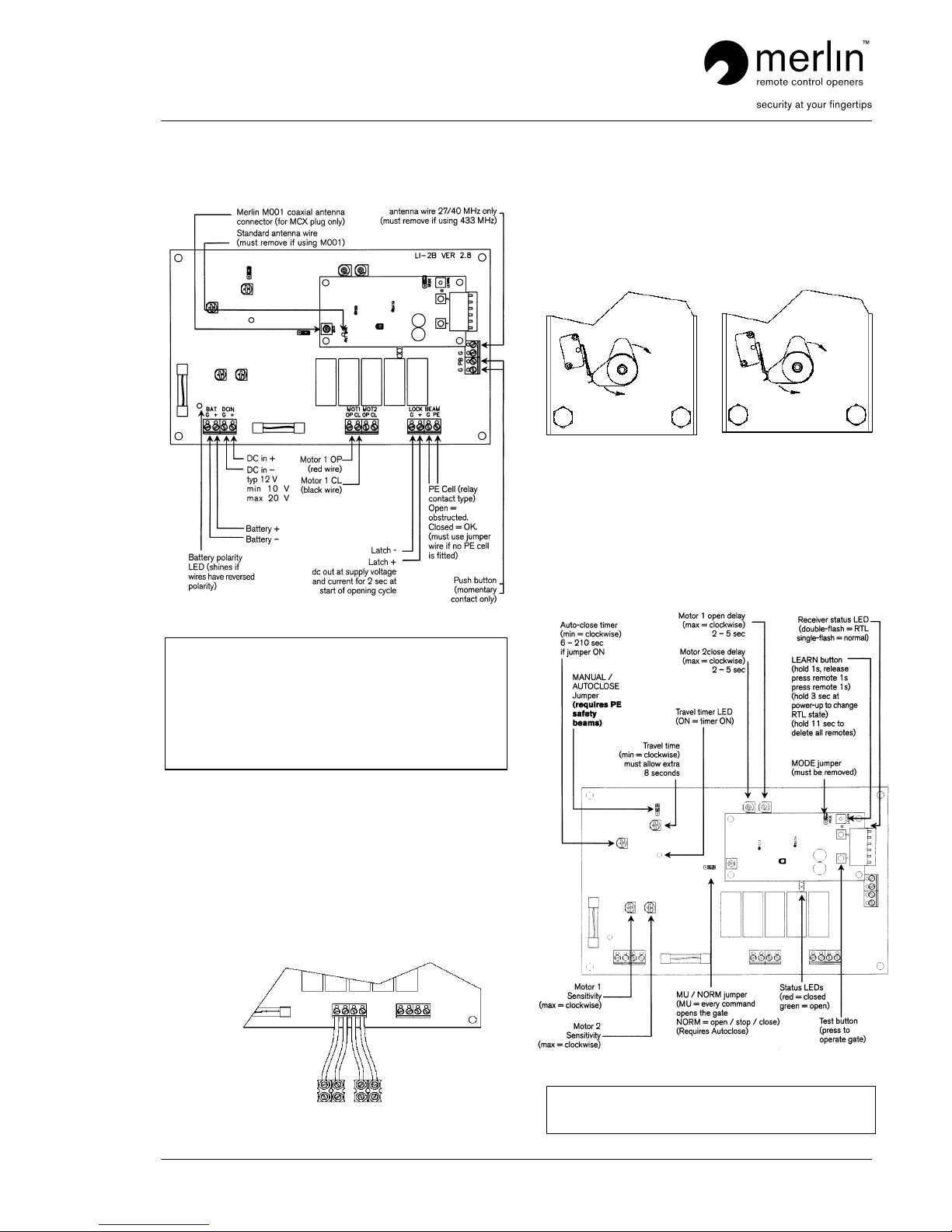
Step 2
Connect the wires to the control board
Note
Step 3
Connect the wires to the motors
Motor 1 is the left hand motor when facing out of the driveway.
If motor 1 is on the right hand side, reverse the polarity of the
motor wires.
If a single motor is fitted use the Motor 1 terminals. If a single
opener is fitted on the right hand side, reverse the polarity of
the motor wires.
If a motor pushes a gate outwards, reverse the polarity of the
motor wires.
OP CL OP CL
Left hand motor Right hand motor
Step 4
Set the travel limits
Do not fully fit the primary arm to the drive before setting the
limits. Leave the bolt loose so that the drive dose not engage
with the arm. This will prevent possible injury or damage
before the limits are correctly set.
Bottom cam/ switch Bottom cam / switch
for opening for opening
limit limit
Top cam / switch Top cam / switch
for closing limit for closing limit
Left hand motor Right hand motor
Close the gates. Operate the motors until there out put shafts
are in the correct position to engage with their primary arms of
the closed gates. Loosen the limit cam cap-screw.
Step 5
Control board set up.
Note
When powering any accessories from the board, (for
example: gate latches, additional receivers, keypads, and PE
beams) ensure the power supply has adequate capacity.
Measure the voltage at the DC IN under full motor load. If it
falls below 9V then the board, receiver, and some
accessories, may not function correctly. In this instance,
remove accessories, upgrade the power supply, or provide
additional power supplies directly to each accessory
Brown
Blue
Blue
Brown
Reverse motor wires if open and close LED’s do not match
gate travel.
Page 3

Installation Instructions
G940 Harmonic swing gate operator (discontinued)
Rev 01, May 03 © Merlin Garage Openers Limited Page 3 of 3
Step 6
Speed selection option
There is a speed selection option on the top of motor.
It is best for long or heavy gates to use the slow speed.
The fast speed option on large gates may cause damage to
the unit due to the forces incurred during operating.
Fast Speed Option
Normal speed option
Fixed connection
Motor terminal block
Factory set on normal speed.
Service
Manual release.
To operate the gates manually, turn the key a quarter turn anticlockwise to the horizontal position. Push in the metal tongue
and manually operate the gates.
Tongue
Maintenance.
In an area where ant or insect infestation is likely, regularly
spray around the opener and any electrical installation with
insecticide.
In normal conditions it is not expected that any additional
lubrication or service is required.
Keep the path of the gate free from debris and foliage.
 Loading...