

Page 1
Installation Instructions
G900 Linear swing gate operator (discontinued)
Rev 01, May 03 © Merlin Garage Openers Limited Page 1 of 2
The Merlin G900 linear actuators are a compact, streamlined
design that provides good performance and quiet operation on
small to medium sized gates. The anodised aluminium finish
protects the drive system from the weather, ensuring low
maintenance. Suitable for single or double swing gates and
provide years of reliable service.
Control box
230v ac or 12v dc 2 wire 12v dc
80
850 365
Specs
Power options 230v. ac, 12v. dc, solar
Current 3 amp per motor
Maximum duty cycle 100%
Travel time 18-20 seconds
Maximum gate weight / length 180Kg / 3 meters
Maximum opening angle 110 deg
Gate stops required Yes
Gate lock required optional
Standard features
Auto close, adjustable 6-210 seconds
Adjustable force sensitivity
Leaf delay for electric locks or clash bars.
Multi-use function.
Optional Accessories
Battery back up
Solar power option
Safety beam sensors
Electric lock
Intercom
Keypad entry.
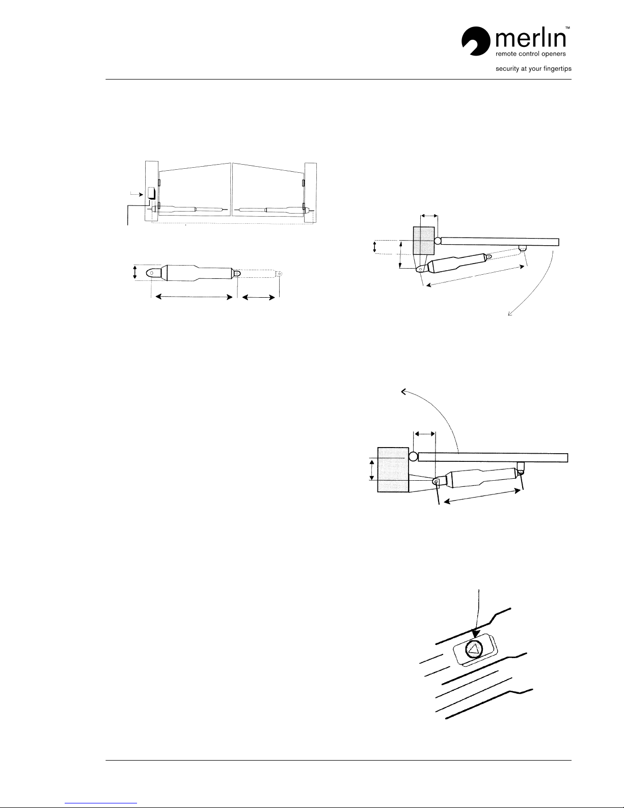
Step 1
Fasten the motor securely to the gatepost, and the gate
bracket to the gate as shown in fig A & B.
Correct geometry must be used.
Fig A
In swinging gates geometry
a
70mm max offset
b
c
Opening angles a b c
90 degrees 160mm 130mm 1215mm
110 degrees 160mm 100mm 1215mm
Fig B
Out swinging gates geometry
a
b
c
Opening angles a b c
90 degrees 160mm 130mm 850mm
110 degrees 160mm 100mm 850mm
To enable the opener to extend out to the gate bracket, turn
the manual release key.
Page 2
Installation Instructions
G900 Linear swing gate operator (discontinued)
Rev 01, May 03 © Merlin Garage Openers Limited Page 2 of 2
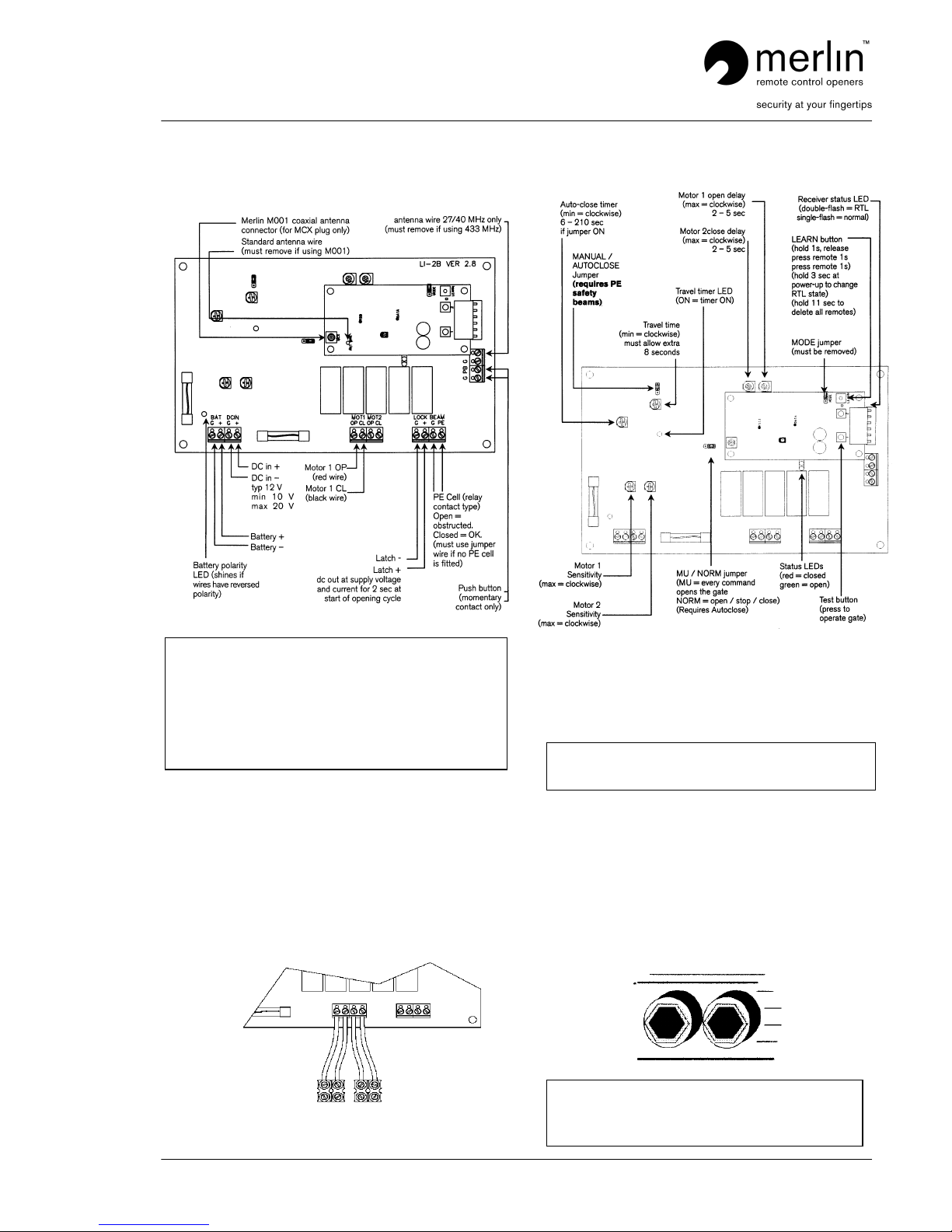
Step 2
Connect the wires to the control board
Note
Step 3
Connect the wires to the motors
Motor 1 is the left hand motor when facing out of the driveway.
If motor 1 is on the right hand side, reverse the polarity of the
motor wires.
If a single motor is fitted use the Motor 1 terminals. If a single
opener is fitted on the right hand side, reverse the polarity of
the motor wires.
If a motor pushes a gate outwards, reverse the polarity of the
motor wires.
OP CL OP CL
Left hand motor Right hand motor
Step 4
Control board set up.
Operate the gates by either a remote control or a push button.
The travel timer pot controls the operators. Adjust the timer so
that the motor/s complete their full open and close cycle plus
an extra 3 seconds of travel time.
the motor clutches will slip and make a clicking sound during
this period.
Note
Step 5
Set clutch torque level
There are two hex nuts on the under side of the motor
housing. These are factory set at approx 20kg and may not
require adjustment.
When the gates reach its stops the clutch should slip untill the
control board deactivates.
Note
When powering any accessories from the board, (for
example: gate latches, additional receivers, keypads, and PE
beams) ensure the power supply has adequate capacity.
Measure the voltage at the DC IN under full motor load. If it
falls below 9V then the board, receiver, and some
accessories, may not function correctly. In this instance,
remove accessories, upgrade the power supply, or provide
additional power supplies directly to each accessory
White
Black
White
Black
Reverse motor wires if open and close LED’s do not match
gate travel.
The same adjustment should be made to both screws
I.e.: if one nut is adjusted 1 turn clockwise, the other
must have the same adjustment.
 Loading...