

Page 1
1
Instructions for installation & use
Toll free helpline
Please have your serial number and
model name available before calling.
Australia 1800 638 234
New Zealand 0800 653 667
United Kingdom 0800 073 0112
www.merlingo.com
G715D
remote control openers
security at your fingertips
sliding gates
residential gate opener for
Page 2

G715D May 05
2
Important safety instructions for
installation
WARNING Incorrect installation can lead to severe injury. Follow all installation
instructions. Merlin Garage Openers Limited does not accept responsibility for
damage or injury resulting from installing this opener.
Prepare the gate for safe automation
Before installing the drive remove or disable any equipment, such as locks, that is not
needed for powered operation.
Check that the gate is in good mechanical condition and that it opens and closes properly.
Do not use force sensitivity adjustments to compensate for a binding or sticking gate.
Excessive force may damage the gate.
Avoid possible entrapment points
Ensure that entrapment between the driven part and the surrounding fixed parts due to the
movement of the driven part is avoided.
Gaps are considered safe as follows (IEC60335-2-103): finger gaps above 25 mm; foot
gaps above 50 mm; head gaps above 300 mm; and whole body gaps above 500 mm.
Add over-ride switch if wicket gate is present
If a wicket gate is present in a gate leaf, it must be fitted with a switch that prevents the
drive from operating when the wicket is open. (Connect a Normally Closed switch to the
STP and GND terminals of the controller board.)
Locate controls carefully
Install any fixed control, wired or wireless, within sight of the gate but away from moving
parts and at a height of more than 1.5 m.
Fit non-contact safety beams
Where they are not already explicitly required to comply with regulations, Merlin strongly
recommends fitting non-contact safety beam sensors.
Locate the entrapment warning sign correctly
After installing the drive, the included entrapment warning sign must be fitted within sight
of anyone that may stand in the path of the moving gate.
Inspect and test the installation
After installation, ensure that the mechanism is properly adjusted and that and the
protection system and manual release function correctly.
Educate the owner
Before handing controls to the user, alert them to the potential dangers, and routine checks
they’re required to perform.
Complete the commissioning check sheet
The commissioning check sheet at the end of this manual must be completed, signed
by the installer and client, and kept on record by the installing company. It contains a
declaration that all safety related procedures have been complied with.
Page 3

3
Important safety instructions for
use
WARNING It is important for the safety of persons to follow all the instructions for
use. Save these instructions.
Controls are not a toy
Do not allow children to play with fixed or remote controls.
Check the gate and drive for wear
Frequently examine the installation for imbalance and signs of wear or damage.
Check that the manual release functions correctly.
Do not use if repair or adjustment is necessary.
Test the safety system every month
Every month, test that the gates stop or reverse in response to an obstruction, and that
interrupting the beam of and photo-electric safety beam also causes the gate to stop or
reverse..
Do not use if repair or adjustment is necessary.
Disconnect power before maintenance
Always disconnect the power supply from the drive before cleaning or maintaining the
gate or drive. The drive or gate may operate unexpectedly due to other users with remote
controls, or due to automatic closing (if enabled).
Become familiar with the controls and manual release before use
Before using the gate and drive, locate the manual release and become familiar with its
operation. Note where the key is located, in the case of a power cut or any failure of the
drive or gate.
Contents
Manually opening the gate 4
Maintenance 4
Learning wireless controls 5
Deleting all wireless controls 5
Deleting selected wireless controls 5
Site requirements 6
Board setup 9
Connections 9
Set the application mode 12
Learn a remote control 1
2
Set the limits of travel 1
2
Template for G715D foundation plate 14
Easy setup 1
7
Controls 1
8
Professional setup 2
1
Testing the gate operation 2
2
Warranty 2
3
Troubleshooting 2
4
Specifications 2
5
Service Centres 2
6
Quick setup guide 2
7
Commissioning check sheet 2
8
Page 4
G715D May 05
4
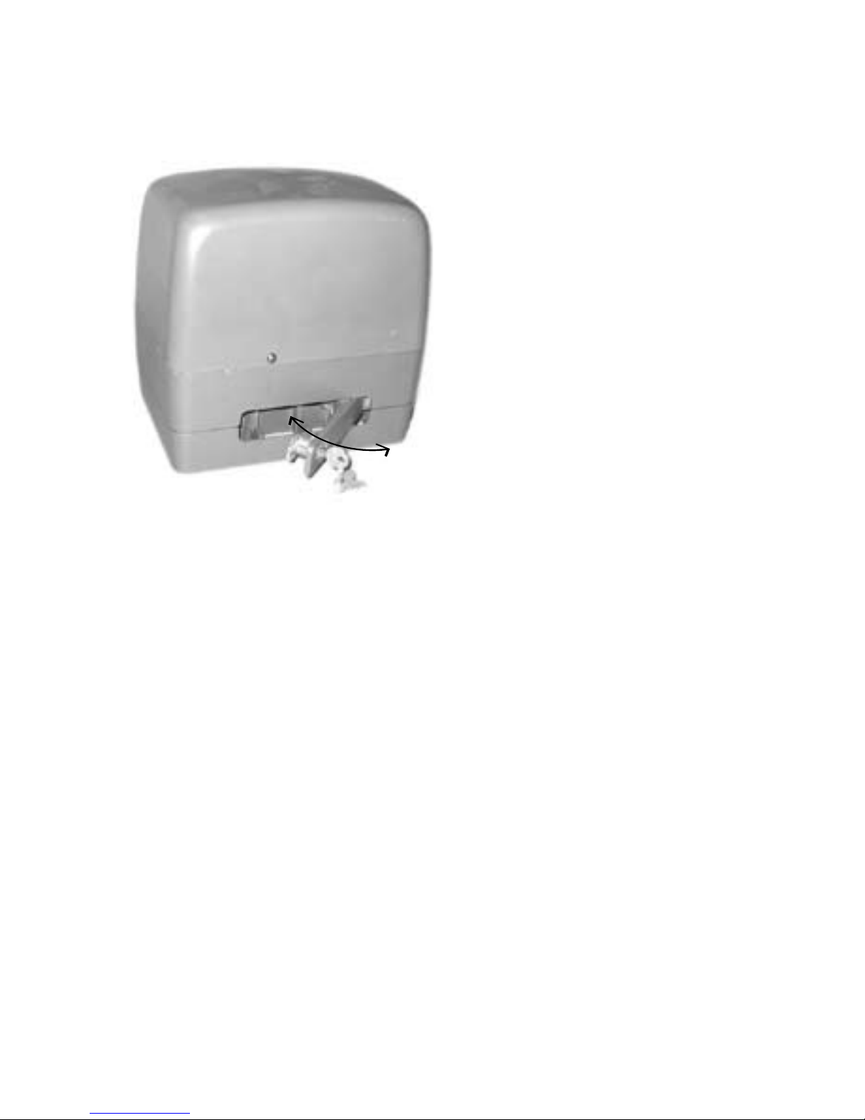
Manually opening the gate
Insert the key provided into the lever on the side of the base of the drive. Turn the key and
pull the lever outwards until it stops.
Maintenance
In an area where ant or insect infestation is likely, regularly spray around the opener and
any electrical installation with insecticide. In normal conditions it is not expected that any
additional lubrication or service is required. Keep the path of the gate free from debris and
foliage.
The gate and its moving parts may sustain damage or wear, presenting additional load to
the opener. Frequently examine the installation for signs of wear or damage. Do not use if
repair or adjustment is needed as the gate may cause injury.
Each month check the sensitivity of your gate while it is closing and opening. Arrange
for an Authorised Installer to adjust if necessary since an incorrect adjustment may be
hazardous.
Each month check that any non-contact beam sensors function correctly by obstructing
them while the gate is moving. The gate should stop, or reverse. Ensure the beams are
clear of any obstructions or dirt and ensure they are aligned towards each other.
Page 5

5
Learning wireless controls
1. Press P2/RADIO until the red LED is lit.
2. If the wireless remote controls are required to only operate Pedestrian Access
mode, install the CH-RADIO jumper over its pins. If the wireless remote controls
are for full access, remove the CH-RADIO jumper.
3. Press the desired button for 3 seconds once on each wireless control that is
required to operate the gate.
NOTE The red LED will blink during learning. The controller is ready for another
wireless control when the red LED is steadily lit.
4. Press P2/RADIO to exit learning mode.
NOTE The learning procedure will time out after 10 seconds of no activity.
Deleting all wireless controls
1. Press and hold the P2/RADIO button until the red LED blinks rapidly.
2. Release the P2/RADIO button.
3. Within 6 seconds, press the P2/RADIO button again to confirm.
Deletion is indicated by the red LED blinking faster.
Deleting selected wireless
controls
The optional accessory GT/SYSTEM hand-held controller is required. Contact Merlin for
details.
Page 6
G715D May 05
6
Site requirements
Check that the temperature range marked on the drive is suitable for the location. Do not
install the drive where ambient temperatures will exceed the ratings.
Gate
This opener is designed for residential
sliding gates of any length, but
weighing less than 500 kg.
Using a spring balance, check that
less than 15 kg force (150 N) is
required to manually move the gate
through its full range of movement,
with the gate disconnected from the
drive.
The gate should operate smoothly,
opening and closing without sticking.
Check the mounting points for
strength and stiffness. Reinforce if
necessary.
Gate posts
There should not be any visible flexing of the mounting points under load.
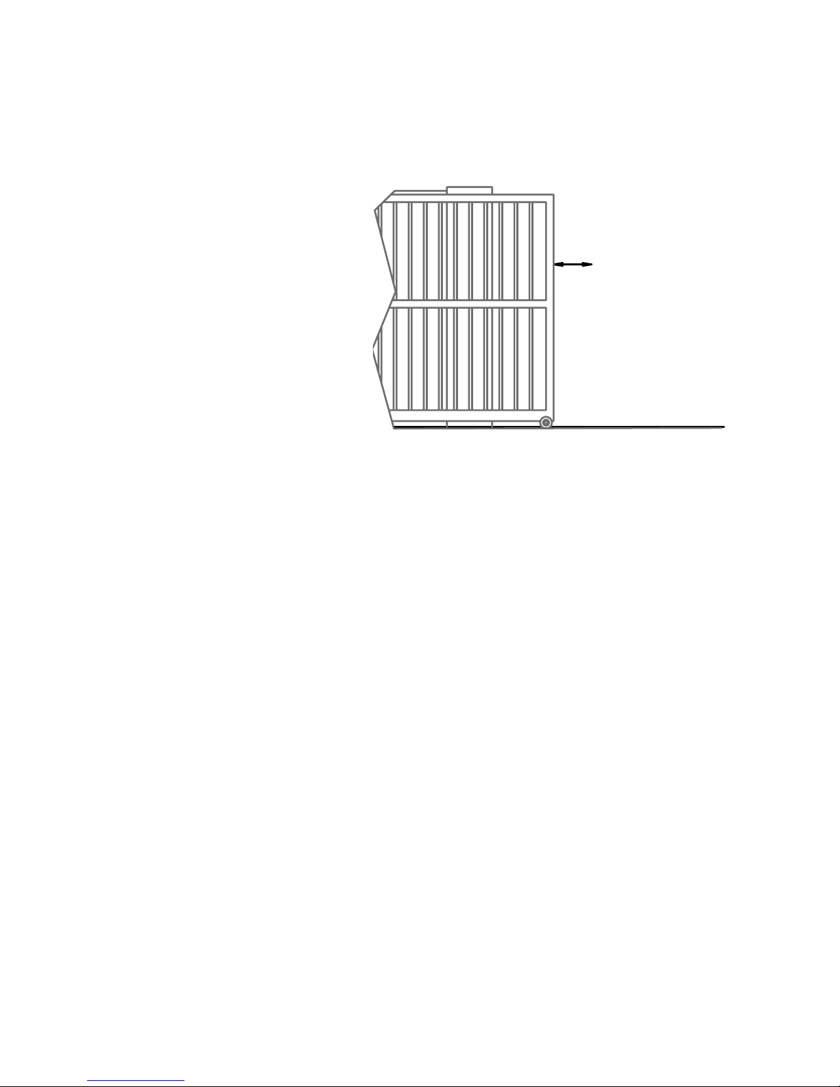
Level and square the gate
The gate track should be perfectly level along its full length. The gate and its tracks and
rollers should not be damaged or bent.
Power supply
Mains powered
If the opener is to be mains-powered, then the 3-pin power plug should be shielded from
the effects of weather. The product is tested as a unit for electrical safety compliance
and if the plug is cut off for hard-wiring, then the electrical safety of the unit becomes the
responsibility of the installing electrician. An isolating switch is recommended, but all mains
wiring should be in accordance with local regulations.
Solar Powered
Contact Merlin for the correct battery and solar panel. The size of these depends on: the
duty cycle of the gates; the hours of sunlight; and the number and type of accessories
fitted.
max 15 kg force
Page 7
7
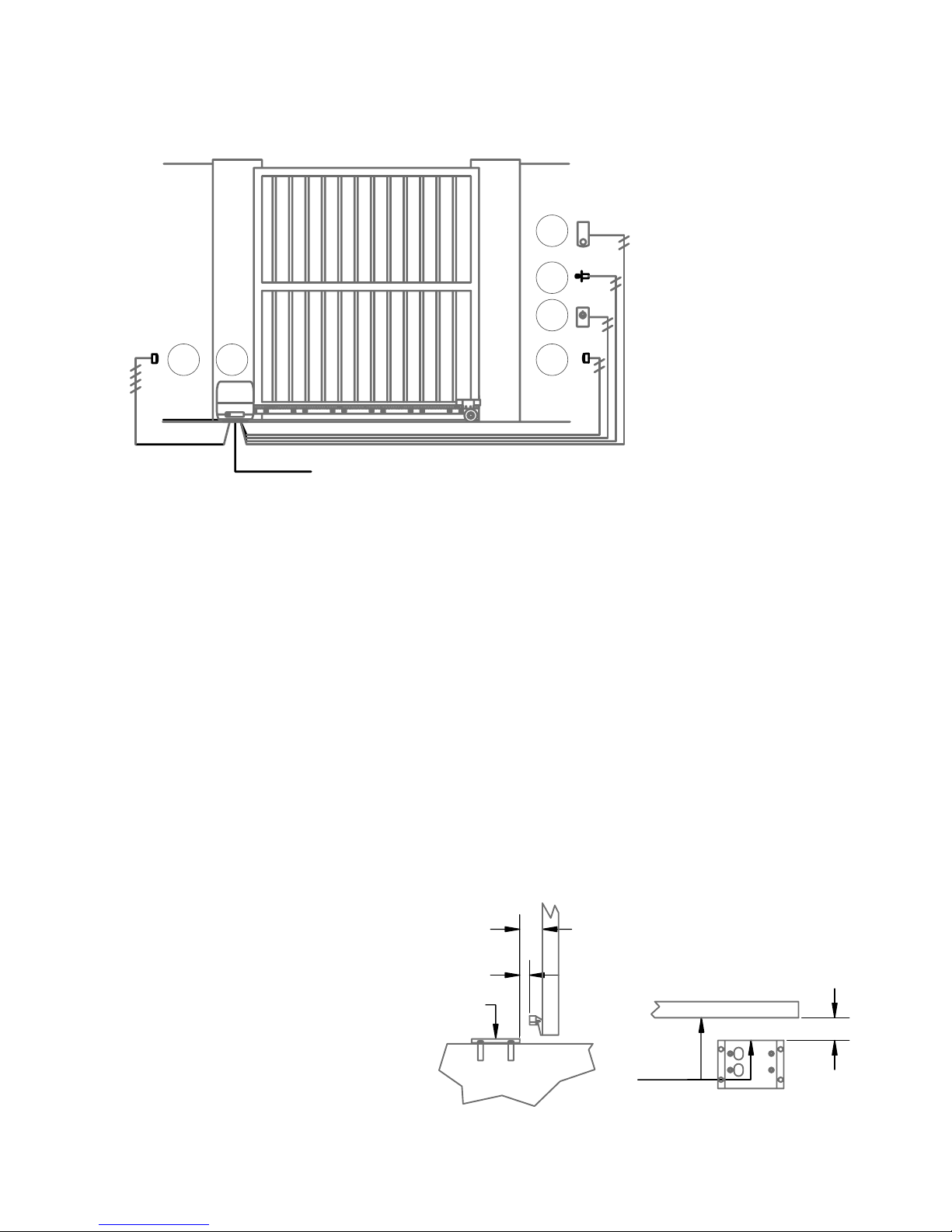
Wiring
All wiring must be arranged to prevent water entering the controller enclosure.
Do not wire mains voltages and low voltage control wires in the same conduit.
1 Opener
2 Receiving IR sensor (4-wire)
3 Transmitting IR sensor (2-wire)
4 Push-button (must be rated suitably for the weather conditions)
5 Keyed switch (must be rated suitably for the weather conditions)
6 Keypad (Merlin M840, wireless, optionally with wired power supply)
NOTE The Merlin M122 wired and M128 wireless pushbuttons are not waterproof, and
are only rated for interior use. The Merlin KWF1 keyed switch is not intended for use fully
exposed to weather in gate installations. Merlin does not warranty any items used outside
their published ratings or intended use.
Installation
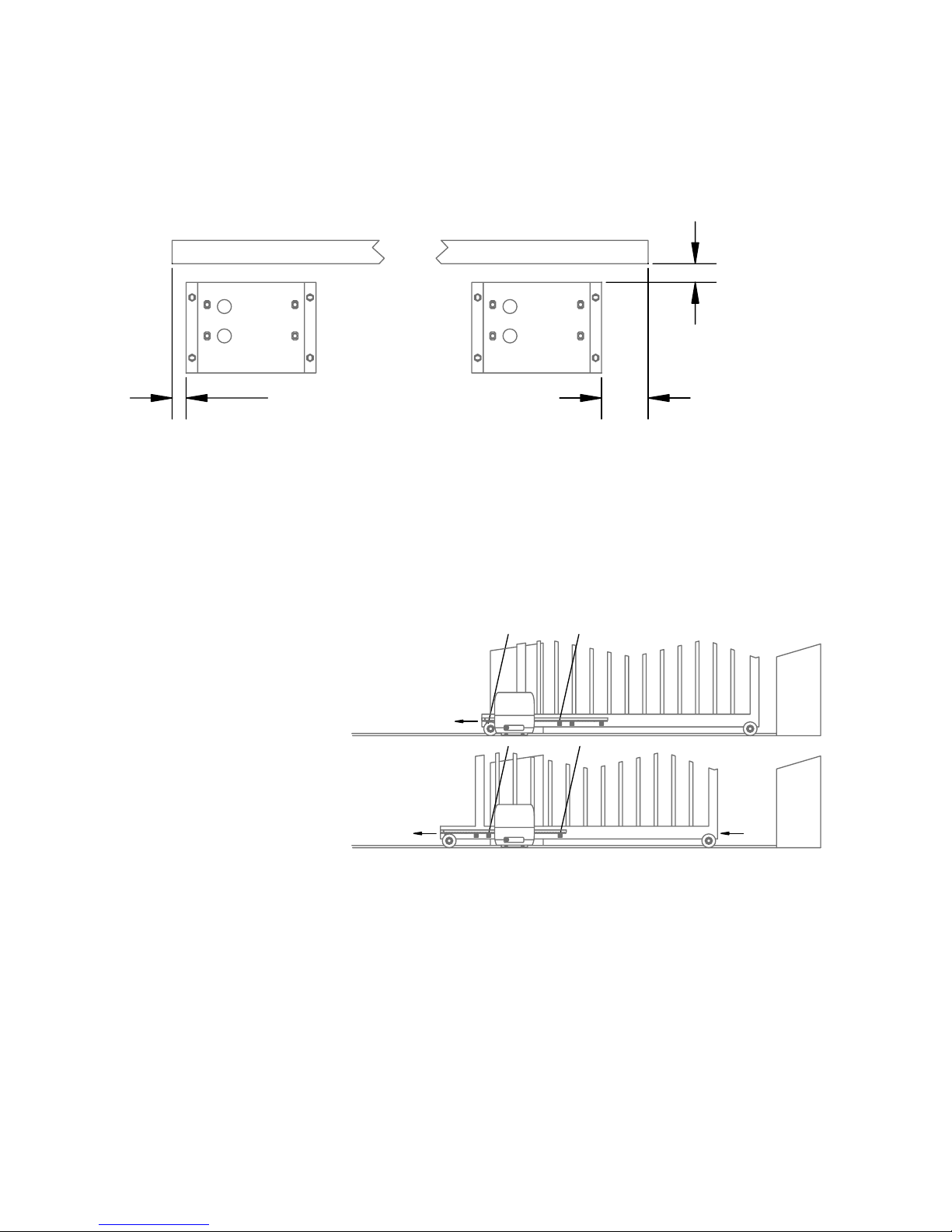
Locating the foundation plate relative to the gate
Position the foundation
plate correct distance from
the face of the gate
Position the foundation plate as
shown. Secure it using concrete and
anchor bolts.
Ensure the cable conduit aligns with
one of the apertures in the plate.
The surface of the foundation plate
must be level and its edge must be
4
5
2 1
6
230-240 V ac
50/60 Hz 100W max
3
must be
level
must be
parallel
70
30 70
gate
ground
Page 8
G715D May 05
8
exactly parallel to the gate. The edge of the plate should be 40 mm from the face of the
gate.
Position the foundation plate correct distance from the ends of the gate
The foundation plate must be positioned to allow the gate to move fully past the opening.
If the supplied limit actuating plates are attached to the rack with no modification then the
gate must extend past the foundation plate as per the measurements shown.
Position the drive on the foundation plate
Remove the cover from the drive and place it on the foundation plate.
Centre the mounting bolts in the drive’s mounting slots.
Fit 2-mm thick spacer shims under the drive – these will be removed aftereards.
Tighten the four bolts ensuring that the drive is parallel to the gate
Operate the manual release clutch, using the key provided, pulling the lever fully out.
Fix the rack to the gate
With the clutch released,
slide the rack over the pinion
gear. Attach one end of the
rack to the gate, then slide
the gate along, attaching
each point of the rack as it
passes the pinion.
Ensure sufficient rack
protrudes past the sprocket
so that the limit actuators are
able to be attached.
Remove the shims
Loosen the bolts holding the drive on the foundation plate; remove the 2-mm shims.
Retighten the four mounting bolts. This provides the correct engagement of the rack and
pinion teeth.
Fit and adjust the limit actuator plates
Allow the gate to slide manually to each end position and fit the limit actuator plates to
the rack, such that the limit switch is activated. This can be fine tuned after the power is
connected to the drive.
gategate
40
100 min30 min
1 2
3 4
Page 9
9
Board setup
It is strongly recommended to follow the procedures in the order below:
1. Make all Connections
2. Set the application mode
3. Learn a remote control
4. Set the limits of travel
5. Run Easy Setup
6. Adjust Controls
7. Run Professional or Easy Setup again
8. Learn wireless remote controls
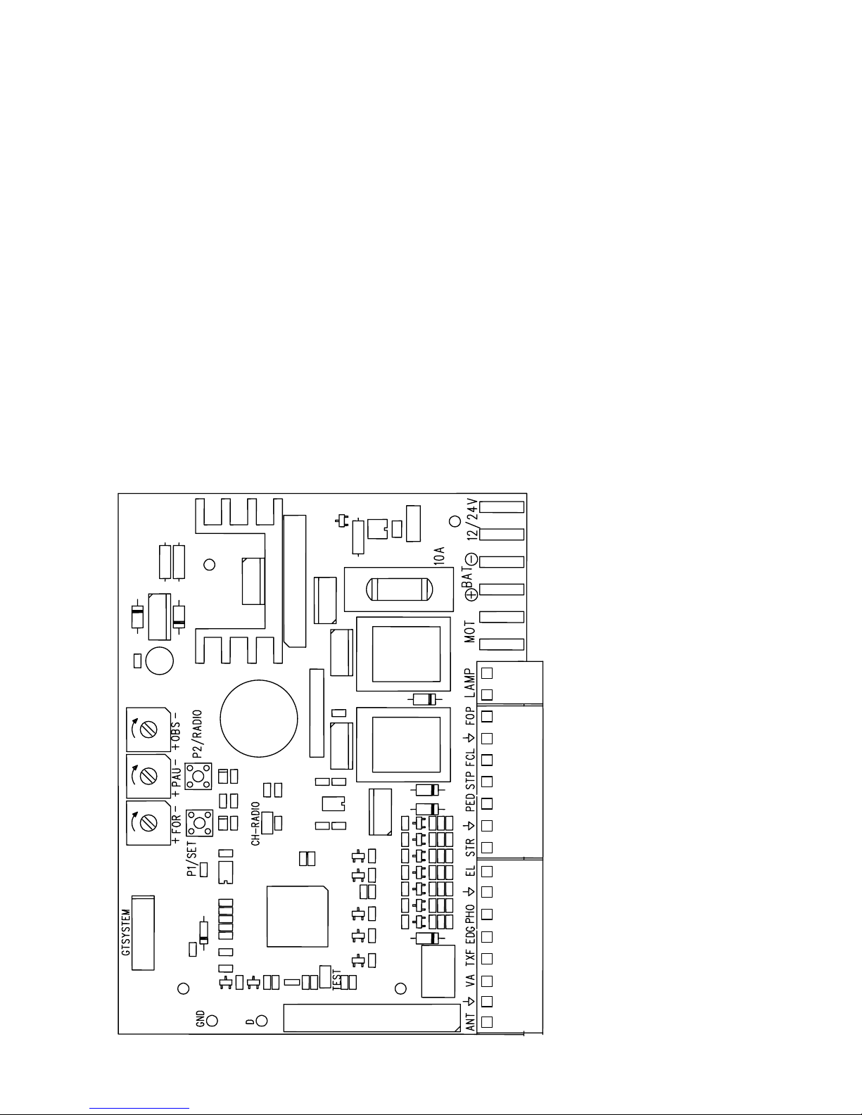
Connections
NOTE When powering any accessories from the board, (for example: gate latches,
additional receivers, keypads, PE beams) ensure the total combined load on the VA and
TXF terminals does not exceed 150 mA. If necessary, remove accessories or provide
additional power supplies directly to each accessory.
transformer in
transformer in
battery in -ve
battery in +ve
motor out
motor out
flashing light out +ve
flashing light out -ve
opening limit switch in (NO)
ground
closing limit switch in (NO)
stop signal in (NC)
pedestrian access in (NO)
ground
start signal in (NO)
lamp / lock module signal out (grey)
ground (black)
photocell signal in (NC )
edge sensor signal in (NO)
transmitting photocell power out
accessory power out (red)
ground
antenna in
Page 10

G715D May 05
10
transformer input
Can accept 12 or 24 V ac, max 100 VA, max 10 A. Use the transformer supplied.
battery input
A 12V 1.2 Ah sealed lead-acid back-up battery is recommended, and should result in
sufficient capacity for at least five operations in the first 24 hours of any mains failure.
motor (MOT) output
If the motor direction is reversed, swap the polarity of the connection wires.
flashing warning lamp output (LAMP)
The outputs are set up for a 2 W flashing lamp, at either 12 or 24 V dc, depending on the
board’s supply voltage. The board supplies power to the lamp, but it is a continuous supply,
so the lamp must have a flashing circuit built in.
The output supplies power to the lamp from 1 second prior to opening, until fully open; and
from two seconds prior to closing, until fully closed.
If the board is running only from battery backup, then the lamp will only flash for the first
four seconds of operation.
courtesy lamp (EXT. LAMP) / electric lock (EL. LOCK)
module output
To connect an electric lock or a courtesy lamp, it is necessary to fit an optional expansion
module. Only one module can be fitted. This must be connected with the three wires
arranged as: red to terminal 3 (VA); grey to terminal 8 (EL); black to terminal 7 (ground).
The ELU Electric Lock Unit module can accept a lock rated at up to 12V 15W.
The LCU Lamp Control Unit module can accept a lamp rated at up to 12V 15W.
tx photocell power output (TXF), photocell signal input
(PHO)
Photocells should have NC (normally closed) contacts when there is no obstruction. Fit a
jumper wire between the signal input terminal and ground if no photocells are fitted.
The maximum total accessory power load allowed is 150 mA. The combined consumption
on the TXF and VA terminals must not exceed this limit. Photocells are part of this total
load.
NOTE 1 If the TEST jumper is fitted, the unit performs a function test on the photocells
before each operation. This adds a 200ms delay before every operation. The transmitting
photocell must be powered from the TXF output. Photocells must have NO (normally open)
contacts when the power is off.
NOTE 2 If the PAU trimmer is set to fully anticlockwise and the photocell beam has been
interrupted, then the gate will close 1 second after the beam is cleared.
NOTE 3 The default behaviour is to react immediately when the beam is interrupted.
Professional Setup Step 12 allows this to be changed. The gate can be made to stop in
response to an obstruction, and then only react after the obstruction is removed.
Page 11

11
accessory power output (VA)
The maximum allowable combined load on the VA and TXF terminals is 150 mA.
Accessories in excess of this limit must be powered directly from the battery.
NOTE Power the transmitting photocell from the TXF output if the TEST jumper is fitted.
start signal input (STR)
This input is NO (Normally Open). When it is momentarily closed to ground the opener will
start. If the gate is already moving then momentarily closing the start input to ground will
stop the movement.
Connect a keyed switch or exit request button to this input.
While this input is closed to ground, any auto-closing function is disabled.
This input can be connected to a timer to force the gate open during certain periods of time.
pedestrian access signal input (PED)
This NO (Normally Open) input can connect to safety devices such as pressure edges, or
to a switch that enables the gate to open.
Activating a safety device will prevent movement from fully open or fully closed, and will
cause movement to reverse while opening. Safety devices connected to PED have no
effect during closing.
A switch connected to the PED terminal will cause only the gate to open. The factory default
setting opens the gate for 5 seconds, and this can be over-ridden using the Professional
Setup routine. The gate will close automatically if auto-close is enabled; otherwise another
manual command is required. Normal opening and closing commands take priority over
Pedestrian Access commands.
It is also possible to activate Pedestrian Access using a wireless remote control that has
been learned while the CH-RADIO jumper is fitted.
stop signal input (STP)
The Stop input is NC (Normally Closed). Fit a jumper if a stop switch is not used. When this
terminal is not connected to ground, the gate will not operate – it will not open or close
until the terminal is reconnected to ground, and it will only restart once a command is sent
through the Start input, or through a learned wireless remote control. If the gate is moving
when this terminal is momentarily disconnected from ground then the gate will stop moving
until the connection is re-established, and another Start command is received.
opening and closing limit switch inputs (FOP, FCL)
Connect to the internal limit switches. .
antenna input (ANT)
The centre wire of a 50-ohm coaxial cable should connect to this terminal. An antenna of
175mm is recommended. Connect the coaxial cable braid to the ground terminal.
A ground plane greatly improves an antenna’s performance. It should connect to the end of
the coaxial cable’s braided screen. An alternative is to mount the antenna through a metal
plate that is at least as large as the ground plane’s length.
Page 12

G715D May 05
12
Set the application mode
WARNING Follow these steps. This setting is an integral part of the safety system. The
controller must be set differently for each motor type and load.
The application mode sets the maximum allowable motor current. In combination with the
FOR setting (motor voltage), and OBS setting (time before reversing from an obstruction),
a safe threshold for the energy applied to an obstruction is set.
Press P1/SET and observe the red LED.
• One flash for Merlin G703 12V sliding gate actuator
• Two flashes for Merlin G715D 24 V sliding gate actuator (required)
• Three flashes for a single Merlin G815D 12V linear actuator
• Four flashes for a single Merlin G915D/G950 12V harmonic actuator
If two flashes do not occur, change the application mode as follows:
1. Press P2/RADIO until the red LED is lit
2. Press P1/SET and observe the number of flashes of the yellow LED. 2 flashes are
required.
3. Press P1/SET again until 2 yellow LED flashes occur
4. Press P2/RADIO to exit programming
Learn a remote control
A remote control is useful for operating the controller during setup.
Press and hold P2/RADIO until the red LED is lit. Press the main button on the remote
control. Wait 10 seconds to exit learning mode.
Install the CH-RADIO jumper. Press and hold P2/RADIO until the red LED is lit. Press the
second button on the remote control. Wait 10 seconds to exit learning mode. Remove the
CH-RADIO jumper.
Now the main remote button will act as P1, and the second button act as P2.
Set the limits of travel
Limit switches must be set before any further setup of the controller board.
Attach the limit switch actuating plates to the rack as required, such that when the gate is
in the fully open and fully closed positions, the limit switch on the drive is triggered.
Page 13

13
Page 14

G715D May 05
Template for G715D foundation plate
M8
Ø8
Ø8
M8
This edge to face the rack, gate, and pinion
Page 15

cable entry hole
NOTE Ensure cables and conduit are pulled through
the cable entry holes when the plate is bolted to the
ground.
Ø8
Ø8
M8
M8
cable entry hole
Page 16

G715D May 05
16
Page 17

17
Easy setup
Easy setup must be performed to set the opening and closing travel times.
NOTE Easy setup only sets the limits and force/speed, and is fully automated; professional
setup also offers slow-stopping and pedestrian access, but is not fully automated. It is an
automated procedure that sets the gate leaf travel times based on the detection of the
limits of travel.
CAUTION During this procedure the gates must be attended. Movement can be stopped
at any point by pressing the P1/SET button. The gate must be in the midway position
before starting this procedure.
To initiate the procedure, press P1/SET then, while the yellow LED is flashing, press P1/
SET again for 1 second.
The following steps are performed automatically:
1. Checks for presence of a motor; photocells (or a jumper) on PHO terminal; e-stop
(or a jumper) on STP terminal.
2. Sets pedestrian opening to half way.
3. Begins to open the gate, with a force set by the FOR trimmer.
NOTE If the gate begins to close first, switch off the power to stop the movement
and then reverse the motor wiring accordingly. Start this setup procedure again.
4. After 3 seconds of opening, gates stop moving.
5. Closes the gate fully, stopping using the closed limit switch.
6. Opens the gate fully, stopping using the open limit switch.
7. Pauses 3 seconds at fully open.
8. Closes fully, slowing down to around 1/3 speed, after 90% of the travel time.
In summary the procedure is: open 3 seconds, close fully, open fully, wait 3 seconds, close
fully.
Page 18

G715D May 05
18
Controls
IMPORTANT If the force/speed/voltage setting (FOR) is adjusted then it is necessary to
perform either Easy Setup or Professional Setup again because the travel times will vary.
Failure to do this risks causing damage to the gates or gate stops.
After every trimmer adjustment press P1/SET to confirm the change. Wait for the LED to
stop flashing.
easy setup / reset button (P1/SET)
Press to reset the board. The board is reset when the yellow LED stops flashing. Press
within 5 seconds of applying power to the board, or while the yellow LED is flashing, to
enter the Easy Setup routine.
Also used in conjunction with P2/RADIO to set the Application Mode, that is how much
maximum motor current is allowed.
enable testing of safety devices
jumper (TEST)
GT/SYSTEM hand held
programmer connection
force/speed/voltage 50 to 100%
(+ FOR -) (cw max voltage)
auto close pause 3 to 60 sec
(+ PAU -)(cw OFF)
obstruction sensing delay
0.1 to 2.5 sec
(+ OBS -) (cw max time)
professional setup /
learn wireless control button
(P2/RADIO)
learn wireless pedestrian access
jumper (CH-RADIO)
easy setup button (P1/SET)
(Press after any
trimmer adjustment)
Page 19

19
learn wireless control button (P2/RADIO)
Press and hold P2/RADIO, until the red LED is lit, to begin learning wireless remote
controls. The red LED will be lit. Press a button for 3 seconds on each wireless control to
be learned. Either wait 10 seconds, or press P2/RADIO again to exit learning. If the CHRADIO jumper is fitted, the wireless controls will operate the pedestrian Access mode; if it
is removed then they will operate the gate normally.
To enter the Professional Setup routine press P2/RADIO within 5 seconds of pressing
RESET, or applying power to the board, or while the yellow LED is flashing.
learn wireless pedestrian access jumper (CH-RADIO)
Place this jumper over the pins when you want to learn wireless remotes for Pedestrian
Access mode.
force/speed/voltage setting trimmer (+ FOR -)
NOTE Press P1/SET after adjusting the trimmer.
The energy transferred to an obstruction is determined by the motor power, and the time
that the power is applied to the obstruction. Motor power is determined by the maximum
voltage and maximum current. This FOR setting alters the motor voltage. The Application
Mode (page 7) alters the maximum allowable motor current. The OBS setting alters the
time that power is applied to an obstruction. So safety is determined by a combination of
the settings for FOR, OBS, and Application Mode.
Turn FOR clockwise to increase the voltage that is applied to the motors.
• Full clockwise: maximum voltage (less sensitive)
• Full anti-clockwise: min. voltage, approx. 50% of the maximum (more sensitive)
NOTE Voltage affects the speed of the motor. After any adjustment to FOR, either the
Easy Setup or the Professional Setup procedure must be completed to set the operating
time correctly.
auto-close pause setting trimmer (+ PAU -)
NOTE Press P1/SET after adjusting the trimmer.
WARNING Photocell sensor beams must be fitted when using auto-close.
This trimmer determines the length of time that the gate pauses before auto-closing.
• Full clockwise: auto-closing is disabled (that is, there is an unlimited pause when
open)
• Full anti-clockwise: pause open for 15 seconds, then auto-close (unless a photocell
is fitted)
• Other positions: adjust for pause times of between 3 seconds and 60 seconds
NOTE In auto-closing mode, any command to open or close will cause the following
behaviour:
• while opening, commands are ignored;
• while closing, commands will cause the gate to start to open;
• while paused open, commands will not close or open, but will restart the pause
timer
Page 20

G715D May 05
20
NOTE If a photocell is connected to the PHO terminal then the response to interruptions
of the beam will vary depending on the setting of the PAU control, and depending on the
choice of option in professional setup:
• PAU full anti-clockwise:
Gate opening - nothing happens if the beam is interrupted
Gate paused open for 15 seconds - if beam is interrupted nothing happens until
the interruption is removed; 1 sec after interruption is removed the gate will close
Gate closing - if the beam is interrupted, then open fully, pause for 1 second, and
begin to close
• PAU in all other positions:
Gate opening – nothing happens if the beam is interrupted
Gate closing - if the beam is interrupted, then open fully
Photocell option setting - see Professional Setup.
If the ‘stop when interrupted, move when clear’ option is enabled in Step 12 of
Professional Setup, the above behaviours will be modified accordingly:
• PAU full anti-clockwise:
Gate opening - stop if the beam is interrupted, continue opening when the beam is
clear, once open the gate will autoclose after 1 second (not 15 seconds as usual)
Gate paused open for 15 sec - if beam is interrupted nothing happens until the
interruption is removed; 1 sec after the interruption is removed the gate will close
Gate closing – stop if the beam is interrupted, then open fully when the beam is
clear, pause for 1 second, and begin to close
• PAU in all other positions:
Gate opening – stop if beam interrupted, continue opening when beam is clear
Gate closing – stop if the beam is interrupted, then open fully when the beam is clear
obstruction sensing trimmer (+ OBS -)
NOTE Press P1/SET after adjusting the trimmer.
Turn this clockwise to make the gate less sensitive, that is to increase the time delay that
occurs before reacting to the detection of an obstacle. Turn anti-clockwise to make the
gate more sensitive to obstructions.
• Full clockwise: maximum time delay of 2.5 seconds before reversing (less
sensitive)
• Full anti-clockwise: minimum time delay of 0.1 seconds before reversing (more
sensitive)
• Other positions: adjust for delay times of between 0.1 and 2.5 seconds
enable testing of safety devices jumper (TEST)
Connecting the TEST jumper across its two pins will cause the controller to verify the
operation of the photocell and / or safety edge before every operation. This test switches
off the power to the safety device and verifies that the device’s output changes state.
Therefore the safety device must be capable of being tested in this way.
A 200 ms delay is created before every movement.
The TEST jumper must be removed if safety devices are not fitted.
Page 21

21
Professional setup
Professional setup is a semi-automated procedure, similar to Easy Setup, but with the
following differences:
• Initiate by pressing P2/RADIO instead of P1/SET
• The installer must intervene to manually operate the gate
• The installer may set a desired slow-down position, if not there will be no slowdown
• The installer must intervene to manually close the gate
• The installer may change the behaviour in response to photocells
• If pedestrian opening is required, then the installer must set it, otherwise pedestrian
opening time is zero
NOTE This procedure sets the gate travel time based on the detection of the limits of
travel. Limit actuating plates must be fitted to the rack.
CAUTION During this procedure the gate must be attended. The gate must be in the
midway position before starting this procedure.
To initiate the procedure, press P1/SET, then while the yellow LED is flashing, press P2/
RADIO again for 1 second.
NOTE It may be more convenient to use a transmitter to control the process, than to press
the P1/SET and P2/RADIO buttons on the controller board. If so, learn one button for P1
(learn the button with the CH-RADIO jumper removed), and one button for P2 (learn the
button with the CH-RADIO jumper fitted).
The following steps are performed automatically:
1. Checks for presence of a motor; photocells (or a jumper) on PHO terminal; e-stop
(or a jumper) on STP terminal.
2. Begins to open the gate, with a force set by the FOR trimmer.
NOTE If the gate begins to close first, switch off the power to stop the movement
and then reverse the motor wiring accordingly. Start this setup procedure again.
3. After 3 seconds of opening, gate stops moving.
4. Closes the gate fully, stopping using the closed limit switch.
The following steps must be performed by the installer:
5. Press either P1/SET or P2/RADIO to begin opening the gate
6. Press P1/SET at the time where M1 slow down to 1/3 speed is required
7. The gate will continue to open fully, stopping using the open limit switch.
The following steps alter the response to interruptions of any photocells. Step 11 makes
no change, Step 12 selects the ‘stop when interrupted, move when clear’ option:
8. Only press P1/SET to close the gates if:
a. photocell is obstructed when closing then reverse immediately, and;
b. photocell is obstructed when opening do nothing
9. Only press P2/RADIO to close the gates if:
a. photocell is obstructed when closing then stop and only reverse when obstruction
is removed, and;
b. photocell is obstructed when opening then stop and continue opening when
Page 22

G715D May 05
22
obstruction is removed
10. The gate will close fully, slowing down at the time previously chosen
Only perform step 11 if pedestrian access is required:
11. Press P1/SET or P2/RADIO. The gate will begin opening. Press P1/SET at the
time where the gate is at the desired open position for pedestrian access. The gate
will close fully and the unit will exit Professional Setup.
12. If Pedestrian Access is not required, press P1/SET and P2/RADIO
simultaneously
NOTE The professional setup procedure will time out after four minutes if abandoned.
Testing the gate operation
Test the operation of all controls and safety devices.
Allow for the effect of weather. Wind or water may make the gates more difficult to move.
If the sensitivity is set to react to extremely light obstructions then the gates may fail to
open or close fully.
After adjustment, check that the force on an obstruction at the far end of the gate leaf
does not exceed 150N (15 kg). Use a spring balance.
Page 23

23
Warranty
Limited warranty
Merlin Garage Openers Limited warrants to the original purchaser (“the Buyer”) that the
controller (“the Unit”) sold under this warranty will be free from defects in materials and
workmanship for a period of 24 months from date of purchase. Accordingly if the Unit
fails due to defects in materials or workmanship within the warranty period Merlin Garage
Openers Limited will, provided the defective part or Unit is returned freight and insurance
prepaid and well packaged to the nearest address listed in this manual, undertake to repair
or, at its option replace, any defective part or Unit and return it to the Buyer at no cost.
Repairs and replacement parts are warranted for the remaining portion of the original
warranty period.
Limitations
It expressly excludes any batteries and malfunctions or defects to the Unit or its operation
due to any of the following:
A Failure to observe installation, adjustment, maintenance or operating instructions
provided with the Unit;
B Incorrect installation, operation or adjustment of products to which the Unit is
fitted;
C Connection to any load outside the specifications set out in the owner’s manual;
D Any modification or repair to the Unit carried by a person not authorised to do so
by Merlin Garage Openers Limited;
E Radio or any other electrical or electronic interference;
F Faulty or unsuitable electrical wiring of the building to which the Unit is attached;
G Faulty or flat batteries in the remote control transmitter;
H Where the defect is due to: conditions other than normal domestic use or dirt,
misuse, neglect, fire, accident, electrical storm or other act of God.
This warranty is void if the labelling has been altered, defaced or moved. The liability of the
Distributor for any loss or damage or injury arising directly or indirectly from any defect in
the goods supplied is limited to the replacement or repair of such goods or to damages
not exceeding the invoice value of such goods at the option of Merlin Garage Openers
Limited.
Future Modifications
Merlin Garage Openers Limited may modify any existing or future model of the Unit without
the obligation to incorporate these modifications into Units already manufactured or into
the Unit to which this warranty applies.
General
This warranty is the only Warranty made by Merlin Garage Openers Limited. All other
warranties, representations and conditions of any kind, express or implied, are hereby
excluded. This warranty does not deprive the Buyer of any rights conferred upon them by
any applicable law or statute in their country of purchase. Proof of date of purchase may
be required when making a claim under warranty. In the event that the Buyer is unable to
provide adequate proof of purchase the date of warranty will apply from date of shipment
from the Distributor to the Reseller.
NOTE Merlin requests that you attach your sales docket or invoice to this manual to enable
you to establish the date of purchase in the unlikely event of service being required.
Page 24

G715D May 05
24
Troubleshooting
Gate will not open or close
The gate should operate smoothly, opening and closing without sticking or requiring undue
force. Release the gate from the opener and check that it is possible to move the gate
freely by hand through the full range of the opening.
May be a power failure. Plug another appliance into the power point to check. Opener may
require service. If solar powered, the battery may not be fully recharging.
SOLUTION: Operate the gate manually. Phone an installer for service.
Gate will open but not close
If photocells are fitted then they may be obstructed or misaligned. The gate mechanism
may have broken, presenting an abnormal load, causing the safety system to activate.
SOLUTION: Look for anything blocking the photocell beam. Is it aligned correctly? Release
the manual release and check the gate can be operated easily by hand. Have your gate
repaired or serviced if it is heavy to move by hand.
Transmitter range is less than normal
Your transmitter battery may be going flat. If you have an external antenna then the wire
may be damaged.
SOLUTION: Replace the transmitter battery. Phone for service if the antenna wire is
damaged
Transmitter doesn’t work some times
There may be occasional radio interference in your area. Your transmitter battery may be
going flat.
SOLUTION: Check for nearby baby monitors, remote control toys, cordless phones.
Replace the transmitter battery.
Radio interference
Gate remote controls are required to operate in shared radio frequency bands. Regulations
permit other users to continuously operate higher powered devices such as baby
monitors or wireless headphones in these shared bands. These devices may cause radio
interference that reduces the performance of the remote control. Switch off interfering
devices if possible. Remote controls and receivers that operate on alternative frequencies
are available at additional cost.
Transmitter doesn’t work at all
Your transmitter battery may be flat.
SOLUTION: Replace the transmitter battery.
Page 25

25
Specifications
Model number G715D
Supply required 230-240V ac, 50Hz
Motor output 24 V dc, max 40 W, max 10A total (fused)
Accessory output 24 V dc, max 150 mA total (fused)
Battery backup (optional) 12 V, 1.2 Ah
Rated load max 180 N (approx. 18 kg force)
Rated duty cycle max 80%
Application residential only
Stand-by power consumption max 0.5 W (with no accessories fitted)
Operating power consumption max 40 W per motor
Gate weight max 500 kg
Operating speed typ 10 m/min
Replacement board fuse 2 A (5 x 20)
Replacement motor fuse 10 A (5 x 20)
Remote control battery Depends on model, either 4LR44 (6V) or CR2025 (3V)
Operating temperature range -20 to +55 °C
Receiver Integrated 433 MHz high-security code-hopping
No. of Users 40 transmitters max
Memory EEPROM, access via GT/SYSTEM
Compatible transmitters All Merlin 433 MHz keyring or wall mounted transmitters,
wireless wall-switches, wireless keypad
NOTE Any additions or alterations outside of these specifications may void the product’s
warranty.
Page 26

G715D May 05
26
Service Centres
If an Authorised Installer installed your unit then call them for prompt on-site service.
See your yellow pages or phone Merlin toll free.
New Zealand
Auckland phone 09 415 4393
Phone toll free 0800 653 667 or 0800 MERLIN
Fax toll free 0800 653 663
Australia
NSW, Vic, Qld, WA
Phone toll free 1 800 638 234
Fax: toll free 1 800 640 243
United Kingdom
Phone toll free in the UK 0800 073 0112
Tel: +44 1709 514 533
Fax: +44 1709 514 534
www.merlingo.com
N2966
Page 27

27
Quick setup guide
WARNING Read the manual! Follow all installation and safety instructions in the manual.
Check Application Mode Set Application Mode
Learn remote controls
Adjust trimmers and set jumpers
Easy setup
Professional setup
+FOR-
force/speed/voltage
50 -100% motor voltage
50%
motor
voltage
100%
motor
voltage
+PAU-
auto-close paus
e
3 to 60 sec
step-by-ste
p
no auto-
close
quick close
after
photocell
+OBS-
obstruction sensing delay
0.1 to 2.5 sec
0.1 sec
delay
2.5 sec
delay
TEST
delay all 0.2 se
c
RESET
red
P2/RADIO P1/SET P1/SET P2/RADIO
red yellow yellow
P2/RADIO P2/RADIO
CH-RADIO
full access
CH-RADIO
pedestrian access
RESET P1/SET
yellow
P2/RADIO
mid-way
P1/SET
P1/SET
P2/RADIO
the photocell is
stop when
obstructed
the photocell
reverse when
is obstructed
P1/SET
yellow
P1/SET
P2/RADIO
+
red red
1 flash: G703
2 flashes: G715D
3 flashes: G815D
4 flashes: G950
/
G915
D
next
existing
setting setting
mid-way
open / close / open / close
P1/SET
P1/SET
Page 28

G715D May 05
28
Commissioning check sheet
Opener model. . . . . . . . . . . . . . . . . . . . . . . . . . . . . . . . . . . . . . . . . . . . . . . . . . . . . . . . . .
Serial numbers . . . . . . . . . . . . . . . . . . . . . . . . . . . . . . . . . . . . . . . . . . . . . . . . . . . . . . . . .
Safety devices
Photo-beam Y / N Pressure sensitive edge Y / N
Connected accessories
Keypad Y / N Solar panel Y / N
Intercom Y / N External antenna Y / N
Number and types of remotes left with client . . . . . . . . . . . . . . . . . . . . . . . . . . . . .
Board settings
Obstruction sensing delay 0.1-2.5 sec (cw max). . . . . . . . . . . . . . . . . . . . . . . . . .
Autoclose 3-60 sec / OFF (cw OFF) . . . . . . . . . . . . . . . . . . . . . . . . . . . . . . . . . . . .
Force/speed/voltage 50-100% (cw max) . . . . . . . . . . . . . . . . . . . . . . . . . . . . . . .
TEST jumper ON / OFF . . . . . . . . . . . . . . . . . . . . . . . . . . . . . . . . . . . . . . . . . . . . . . . .
Gates
New or existing . . . . . . . . . . . . . . . . . . . . . . . . . . . . . . . . . . . . . . . . . . . . . . . . . . . . . . . .
Leaf width x height . . . . . . . . . . . . . . . . . . . . . . . . . . . . . . . . . . . . . . . . . . . . . . . . . . . . .
Construction type / % coverage. . . . . . . . . . . . . . . . . . . . . . . . . . . . . . . . . . . . . . . . .
Load measured at gate bracket, without opener connected . . . . . . . . . . . . . . .
Contact details
Signed by installer. . . . . . . . . . . . . . . . . . Signed by client . . . . . . . . . . . . . . . . . . . .
Date. . . . . . . . . . . . . . . . . . . . . . . . . . . . . . . Date. . . . . . . . . . . . . . . . . . . . . . . . . . . . . . .
Installer name. . . . . . . . . . . . . . . . . . . . . . Client name. . . . . . . . . . . . . . . . . . . . . . . .
Company . . . . . . . . . . . . . . . . . . . . . . . . . . Installation address . . . . . . . . . . . . . . . . .
. . . . . . . . . . . . . . . . . . . . . . . . . . . . . . . . . . . . . . . . . . . . . . . . . . . . . . . . . . . . . . . . . . . . . . .
The client acknowledges that all safety systems, including photo beams, have been fully
explained to them.
Comments. . . . . . . . . . . . . . . . . . . . . . . . . . . . . . . . . . . . . . . . . . . . . . . . . . . . . . . . . . . . .
This sheet must be completed by the installer, and signed by both the client and the
installer. It must be kept on record by the installing company.
 Loading...