

Page 1
+
with Security+ 2.0
APPLICATION
The receiver can be used as a single or three channel receiver to
control up to 3 gates, commercial operators or residential door
openers. The receiver can also be used with a 3-button remote
control to operate the OPEN, CLOSE and STOP feature on a
commercial door operator.
The E860 Weather Resistant Universal Receiver may be mounted
in outside locations that may be exposed to rain or moisture.
Each channel is compatible with a specified number of remote
controls and keypads. Refer to the list below:
• CH1: 50 remote controls and 2 seperate keypads
• CH2: 20 remote controls and 2 seperate keypads
• CH3: 20 remotecontrols and 2 seperate keypads
CH1 & CH2 have Normally Open dry contact outputs.
CH3 has both Normally Open & Normally Closed dry contact
outputs.
When the channel has reached full capacity for remote controls,
all LEDs will blink 3 times. When the channel has reached full
capacity for keypads, all LEDs will blink 4 times. Additional
accessories can be programmed, however, the newly
programmed accessory will replace the first programmed
accessory.
NOTE: The receiver will only allow you to program a button on the
remote control to one channel at a time. For example, if the button
on the remote control or keypad is already programmed to channel
1 and then is programmed to channel 3, the button will be erased
from channel 1 and will only work on channel 3.
Momentary Closure:
The outputs are automatically programmed for a momentary closure
of 0.4 seconds when using hand held remote controls E945M, etc.
Constant Closure Output:
The outputs are automatically programmed to remain closed when
receiving a constant signal (press & hold) only when using Keypads
and wireless wall controls (E840M, E128M,E138M etc).
WEATHER RESISTANT UNIVERSAL RECEIVER
MODEL E860
To prevent possible SERIOUS INJURY or DEATH from electrocution:
•
Be sure power is NOT connected BEFORE installing the receiver.
To prevent possible SERIOUS INJURY or DEATH from a moving gate
or garage door:
• ALWAYS keep remote controls out of reach of children. NEVER
permit children to operate, or play with remote control transmitters.
• Activate gate or door ONLY when it can be seen clearly, is properly
adjusted, and there are no obstructions to door travel.
• ALWAYS keep gate or garage door in sight until completely closed.
NEVER permit anyone to cross path of moving gate or door.
To prevent possible SERIOUS INJURY or DEATH, the use of
CONSTANT OPERATION on residential openers is PROHIBITED.
When a receiver is used to activate a commercial door opener, a
reversing edge MUST be installed on the bottom of the door. Failure to
install a reversing edge under these circumstances may result in
SERIOUS INJURY or DEATH to persons trapped beneath the door.
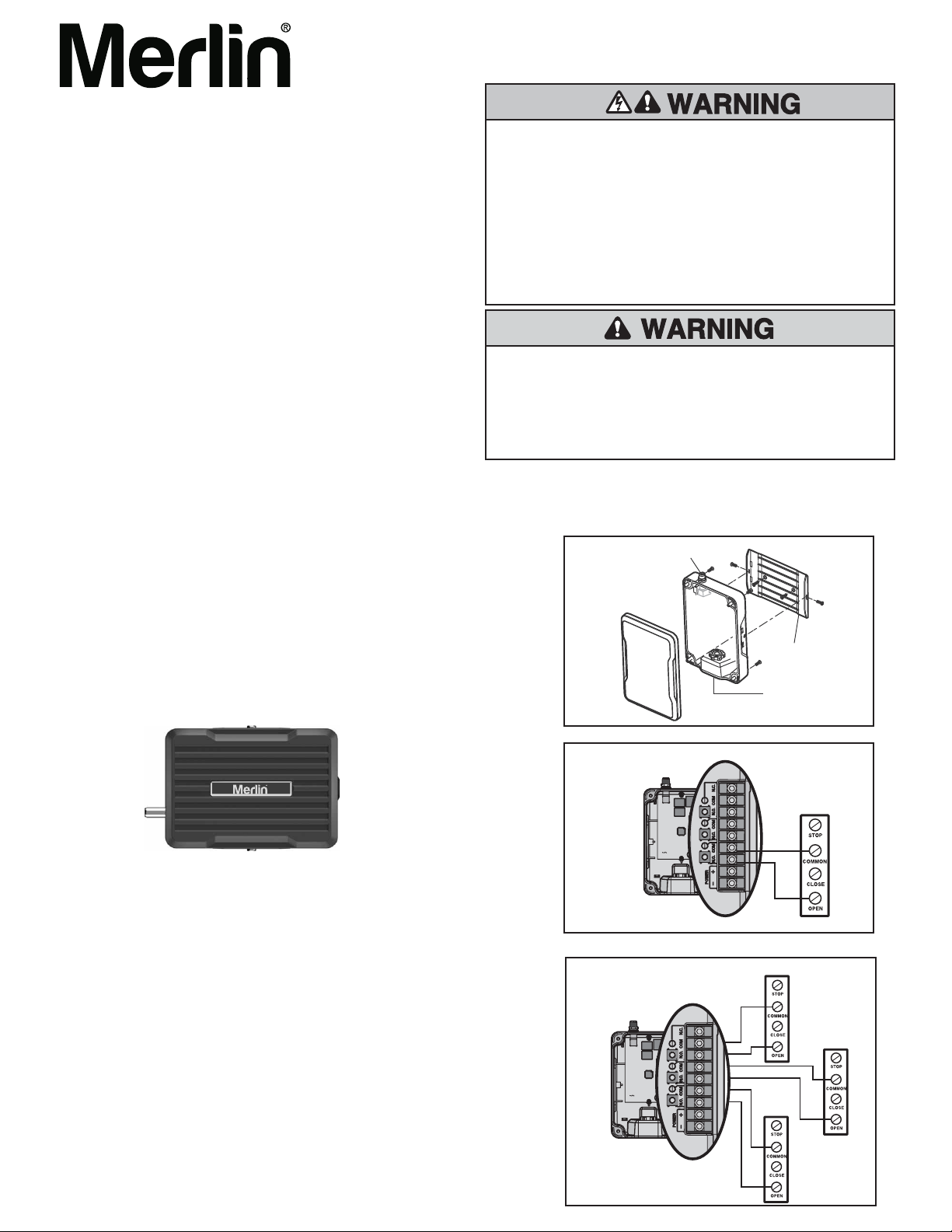
WIRING
Refer to your commercial door operator or gate operator owner
manual or wiring diagrams for specific wiring information.
Figure 1
Antenna
Connector
Mounting Bracket
Watertight Connector
INSTALLATION
1. Select a convenient location near the opener to be controlled by the
receiver within “line of sight” of the intended transmitting location.
NOTE: Avoid mounting the receiver in a metal enclosure or near
other wireless receiving or transmitting devices.
2. Mount the bracket to the desired surface with appropriate hardware
(not provided) ( Figure 1).
3. Remove the 4 (#8) screws on the back of the receiver and remove the
faceplate.
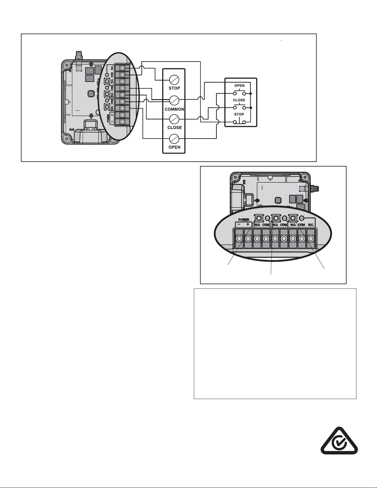
4. Make wiring connections (Figures 2,3 & 4). Refer to your gate or
commercial door opener owner’s manual for more specific information.
Connect power from your operator, or from a powerpack, to the PWR
terminals (9-30 VAC or 12-40 VDC).
5. Refer to the PROGRAMMING instructions in this manual and program
the remote controls to the receiver.
6. Secure the faceplate with the 4 (#8) screws previously removed.
7. Install the antenna provided.
8. Snap the receiver onto the mounting bracket and secure with the (#8)
screws provided.
9. Tighten the watertight connector to secure and seal the wiring.
Figure 2
Receiver
Figure 3
TWO & THREE CHANNEL
Receiver
SINGLE CHANNEL
Single Operator(s)
Operator 3
Operator 2
Operator 1
Page 2
WIRING CONTINUED
Figure 4
OPEN/CLOSE/STOP
Single Operator
Receiver
PROGRAMMING
PROGRAM A SINGLE BUTTON REMOTE CONTROL
1 Press and release the Learn button for the selected channel on
the receiver. The corresponding LED will glow steadily for 30
seconds.
2 Within 30 seconds press and hold the button on the remote
control that you wish to program to the receiver.
3 Release the remote control button when the LED on the
receiver blinks, then turns off. Programming is complete.
Repeat the steps above for each remote control you would like to
program.
PROGRAM A 3-BUTTON REMOTE CONTROL AS OPEN,
CLOSE, AND STOP
1 Press and release the CH1 Learn button on the receiver.
2 Within 30 seconds press the desired OPEN button on the
remote control.
3 Press and release the CH2 Learn button on the receiver.
4 Within 30 seconds press the desired CLOSE button on the
remote control.
5 Press and release the CH3 Learn button on the receiver.
6 Within 30 seconds press the desired STOP button on the
remote control.
NOTE: If a remote control button is not pressed within 30
seconds, the LED next to the selected Learn button will turn OFF.
In that case, repeat the programming.
TO ERASE THE MEMORY
1 Press and hold the Learn button for the channel you want to
erase. Release the button when the corresponding LED turns
off; the memory has been erased.
FOR TECHNICAL SUPPORT DIAL OUR TOLL FREE NUMBER:
1800 638 234
Operator 1
3-Button Control Device
Refer to your commercial
door operator or gate
operator wiring diagrams
for instructions on
connecting two or more
3-Button control devices.
CH1 Learn Button
CH2 Learn Button
CH3 Learn Button
SPECIFICATIONS
Contact Rating ........ . . . . . . . . 5 Amps 28 Vac or dc Max.
Power ............ . . . . . . . .9-30V AC or 12-40 V DC, 50mA
RF
Frequency: ....................... . . . . . . . . . 433MHz
IP Rating ............ . . . . . . . . . . . . . . . . . . . . . . . . . . IP 45
NOTE: If your operator does not meet the power specifications
you will need a low voltage power supply.
COMPATIBLE ACCESSORIES
Remote Controls . . . . Models E960M,E945M, E940M, E943M
Keypads
Wireless Wall Controls . . . . . . . . . . . . . Models E128M, E138M
Antenna Extension Kits ............ . . . . . . . . Models 86LM
Antenna Only ....................... . . . . . . . .K77-36541
CHAMBERLAIN AUSTRALIA PTY LTD
PO BOX 1446
LANE COVE NSW 1595
PHONE TOLL FREE: 1800 638 234
CHAMBERLAIN NEW ZEALAND LTD
PO BOX 100221
NORTH SHORE 0745
PHONE TOLL FREE: 0800 MERLIN
gomerlin.com.au
gomerlin.co.nz
. . . . . . . . . . . . . . . . . . . . . . . . . . . . . . . Models E840M
114A4998A
 Loading...