

Page 1
Merlin CT1250 Gas Interlock System Product Data Sheet
Vent Direct Ltd 1
Gas Safety Products
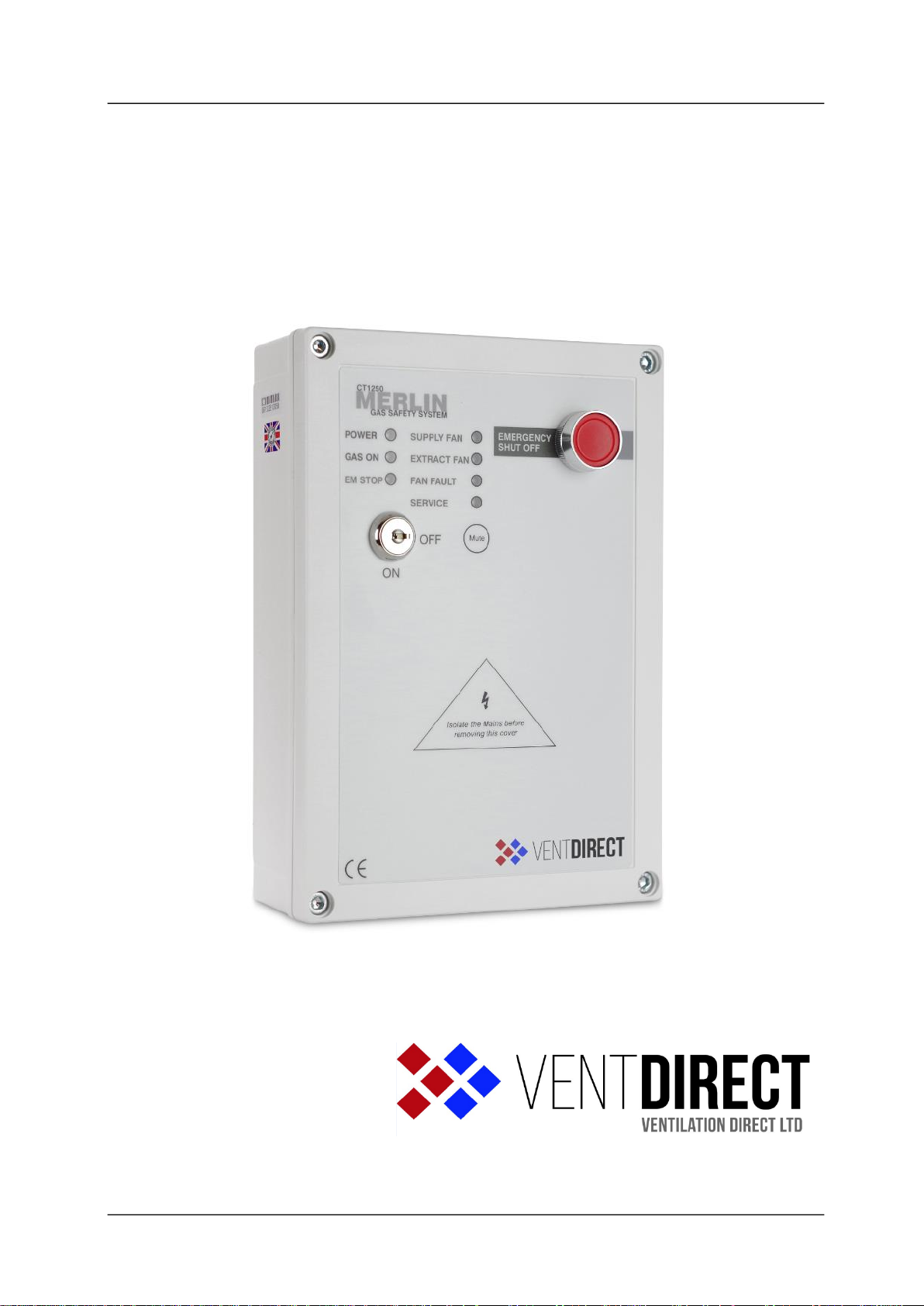
Merlin CT1250 Gas Interlock System
Page 2

Merlin CT1250 Gas Interlock System Product Data Sheet
Vent Direct Ltd 2
Installation, operating and maintenance
12/05/2017
Table of contents
1 General information .......................................................................................... 3
2 Installation ......................................................................................................... 3
2.1 Panel Mounting.. ............................................................................................................. 3
2.2 Mains Supply................................................................................................................... 3
2.3 Gas solenoid valve.. ........................................................................................................ 3
2.4 Air Pressure differential Switches. .................................................................................. 3
2.5 Current Monitor. .............................................................................................................. 3
2.6 BMS Connections. .......................................................................................................... 3
2.7 Remote emergency shut off buttons. .............................................................................. 3
2.8 Internal Buzzer. ............................................................................................................... 3
2.9 Service Mode. ................................................................................................................. 4
3 Operation Instructions ...................................................................................... 4
3.1 How to turn the system on and off .................................................................................. 4
3.2 Explanation of LED status ............................................................................................... 4
3.2.1 Power LED ...................................................................................................................... 4
3.2.2 Gas on LED..................................................................................................................... 4
3.2.3 EM Stop LED .................................................................................................................. 4
3.2.4 Supply fans LED ............................................................................................................. 4
3.2.5 Extract fans LED ............................................................................................................. 4
3.2.6 Fan Fault LED ................................................................................................................. 4
3.2.7 Service LED .................................................................................................................... 5
3.3 Using the emergency shut off ......................................................................................... 5
3.4 BMS integration .............................................................................................................. 5
3.5 Fire alarm integration ...................................................................................................... 5
4 CT1250 Wiring Diagram ................................................................................. 6
Page 3

Merlin CT1250 Gas Interlock System Product Data Sheet
Vent Direct Ltd 3
1 General information
The Merlin CT1250 is a ventilation interlock panel with two built in current monitors.
The Merlin CT1250 can receive connections from either remote air pressure differential
switches or the internal current monitor & remote emergency shut-off buttons. It can also be
integrated with a BMS and fire alarm.
It is recommended that the user reads this guide before using the system. Please do NOT
attempt to operate the unit until the contents of this document have been read and are
thoroughly understood.
2 Installation
2.1 Panel Mounting. The control panel is designed for surface mounting using 4 mounting screws.
Removing the cover on the panel gives access to the circuit board.
2.2 Mains Supply. A 230-volt electrical supply should be supplied to the panel. This should be
externally fused at 3 Amps using a fused spur and should be connected to the terminals
marked ”LNE Power IN”
2.3 Gas solenoid valve. The gas solenoid valve should be powered using the terminals on the
Merlin CT1250 marked “LNE to VALVE”.
2.4 Air Pressure differential Switches. These terminals are linked out as a factory setting. Wiring
to the air pd switches should be made using two-core volt free connections. The wiring
connections should be made from the terminals marked “FAN PD SWITCHES”. If supply and
extract air pd switches are being used terminals marked “SUPP FAN” and “EXTR FAN” should
be used. If only one fan is being used the terminals not in use should be left linked out.
2.5 Current Monitor. On the base of the circuit board there are two sets of terminals, one marked
“SUPP FAN LIVE” the other marked “EXTR FAN LIVE”. If you are monitoring the fan by
measuring electrical current going to the fan these terminals should be used. The live feed
from the fan controller should be taken to the Merlin CT1250 and connected to either the
supply or extract side depending on which fan or fans are being monitored. On the circuit
board just above the “Live feed” there is a potentiometer marked “sens 1” on the supply fan
side and marked “sens 2” on the extract side. The fan should be run at minimum speed and
the potentiometer turned clockwise until the green LED on the PCB, located below the
potentiometer, lights up.This indicates the panel has seen the electrical current going to the
fan. If a second fan is connected this procedure should then be repeated on the other
potentiometer. The panels are sent from the factory with links in the terminal connections
marked “Fan PD Switches supp fan & Extr fan” These terminals are low voltage, mains supply
must NOT be introduced to these terminals. If both supply fans and extract fans are being
monitored both theses links should be removed. If only one fan is being monitored the relevant
link should be taken out of the terminal connection.
2.6 BMS Connections. Terminal connections are available on the circuit board for connections to
Building Management systems etc. Detailed on the circuit board as “TO BMS N/C, Com and
N/O” these are volt free connections.
2.7 Remote emergency shut off buttons. The terminal for remote emergency shut-off buttons is
detailed on the circuit board as “EM Rem”. These connections are linked out as a factory
setting. Remote emergency shut-off buttons should be volt free and wired to the Merlin
CT1250 using two-core cable.
2.8 Internal Buzzer. Operates at 65dB measured 30cm from closed panel.
Page 4

Merlin CT1250 Gas Interlock System Product Data Sheet
Vent Direct Ltd 4
2.9 Service Mode. The service dip switch inside the Merlin CT1250 can be used to allow the
gas valve to remain open for 4 hours without the fans running on each activation of the key.
Note: all low voltage connections should be made using a screened cable to
avoid electrical interference.
3 Operation Instructions
3.1 How to turn the system on and off
1. Turn the Fans On.
2. Turn the key switch to on position.
3. To turn the system off, turn the key switch to off position.
3.2 Explanation of LED status
3.2.1 Power LED
When the system is connected to the mains supply, the Power LED will illuminate. When no
power is present, this LED will not light up.
RED = OK
OFF = No power to CT1250, a loose ribbon connection or the fuse may not be intact.
3.2.2 Gas on LED
When the fans are running at the correct speed and the key switch is turned on, the Merlin
CT1250 will open the gas valve and the green ‘Gas On’ LED will illuminate.
GREEN = Gas On
OFF = Gas Off
3.2.3 EM Stop LED
If an emergency shut off button (either remote or on the panel) is pressed, the LED will
illuminate AMBER and the gas will be turned off. The EM Stop button must be re-set before
restarting the system.
OFF = OK
AMBER = EM Stop button pressed
3.2.4 Supply fans LED
Under normal working the LED will illuminate GREEN. If a supply fan fault is present, the LED
will be flashing.
GREEN = OK
FLASHING = The supply fan is not running.
3.2.5 Extract fans LED
Under normal working the LED will illuminate GREEN. If a supply fan fault is present, the LED
will be flashing.
GREEN = OK
FLASHING = The extract fan is not running
IF SUPPLY AND/OR EXTRACT FANS LED FLASHES FOR MORE THAN 20 SECS, THE
Merlin CT1250 WILL SHUT OFF THE GAS.
3.2.6 Fan Fault LED
Under normal working conditions this LED is off. If a fan fault is present for more than 20
seconds, the LED will illuminate AMBER.
OFF = OK
Page 5

Merlin CT1250 Gas Interlock System Product Data Sheet
Vent Direct Ltd 5
AMBER = the gas supply has been shut off due to a ventilation fault.
WHEN A FAULT IS PRESENT YOU WILL NEED TO CONTACT YOUR
SERVICE/MAINTENANCE COMPANY.
YOU SHOULD NOT ATTEMPT TO CARRY OUT A REPAIR OR RECTIFY THE FAULTS
UNLESS YOU ARE QUALIFIED TO DO SO.
3.2.7 Service LED
When the service light is illuminated this means the service dip switch inside the Merlin
CT1250 has been placed in the “on position”.
This will bypass the fans for 4 hours on each activation of the key in order to open the gas
solenoid valve. At the end of the 4 hours the gas will shut off and the service LED will flash.
3.3 Using the emergency shut off
The Emergency shut off button is located on the front of the panel. There is also a facility for
remote shut off buttons to be wired in series.
The Emergency shut off button(s) will cut off the gas supply when activated.
To reinstate the system, the Emergency shut off button(s) will need to be reset and the panel
restarted.
3.4 BMS integration
The Merlin CT1250 can be integrated with a BMS to make or break a circuit on gas on/gas off,
(valve open or valve closed). This will tell the BMS whether or not the kitchen has use of the
gas supply.
3.5 Fire alarm integration
The Merlin CT1250 can be integrated with a fire alarm to close the gas supply automatically in
the event of a fire.
The volt free fire alarm signal can be wired in series with any remote emergency shut off
buttons.
If there is no remote emergency stop buttons installed wire this directly to the terminal marked
‘EM REM’.
Page 6

Merlin CT1250 Gas Interlock System Product Data Sheet
Vent Direct Ltd 6
CT1250 Wiring Diagram
1. Mains Input 230VAC
2. Gas Solenoid Valve Power Output, 230VAC.
3. BMS output contacts. Normally Closed, Common and Normally Open.
4. Remote EM Stop buttons and Fire Alarm input wired in series (purchased separately). VOLT
FREE INPUT
5. Supply Fan external pressure differential switch or current switch. VOLT FREE INPUT
6. Extract Fan external pressure differential switch or current switch. VOLT FREE INPUT
7. Supply Fan current monitor, MAX 20AMPS
8. Extract Fan current monitor, MAX 20AMPS
9. Potentiometers.
10. Service switch.
Please note, Mains wires and low voltage wires should
not be run in the same conduit as per the LOW
VOLTAGE DIRECTIVE
Page 7

Merlin CT1250 Gas Interlock System Product Data Sheet
Vent Direct Ltd 7
CONTACT US:
Vent Direct Ltd
Vantage Cl,
Sheffield
South Yorkshire
S9 1RS
Tel - 0114 2573455
www.ventdirect.co.uk
info@ventdirect.co.uk
Rev
Date
Author
Description
04
12/05/2017
BT
Merlin CT1250 Product Data Sheet – Fourth Issue
Page 8

Merlin CT1250 Gas Interlock System Product Data Sheet
Vent Direct Ltd 8
 Loading...