

Page 1
1
MJ3800MYQ
Residential Sectional Wi-Fi Garage Door Opener
Installation and Operating Instructions
gomerlin.com.au
gomerlin.co.nz
Owners Copy: Please keep these instructions for future reference
This manual contains IMPORTANT SAFETY information
DO NOT PROCEED WITH THE INSTALLATION BEFORE READING THOROUGHLY
®
Page 2
2
START BY READING THESEI MPORTANT SAFETY INSTRUCTIONS
Keep garage door balanced. Do not let the garage door
opener compensate for a binding or sticking garage door.
Sticking, binding or unbalanced doors must be repaired
before installing this opener.
Do not wear rings, watches or loose clothing while
installing or servicing a garage door opener. Wear gloves,
safety goggles and suitable protective clothing where
appropriate.
Frequently examine the door installation, in particular
cable, springs and mountings for signs of wear, damage
or imbalance. Do not use if repairor adjustment is needed
since springs and hardware are under extreme tension and
a fault can cause serious personal injury.
To avoid serious personal injury from entanglement,
remove all ropes, chains and locks connected to the
garage door before installing the door opener.
Installation and wiring must be in compliance with your
local building and electrical codes.
The safety reverse system test is very important. Your
garage door MUST reverse on contact with a 40mm
obstacle placed on the floor. Failure to properly adjust the
opener may result in serious personal injury from a closing
garage door. Repeat the test once a month and make any
necessary adjustments.
Use the Manual Release only for the seperation of the
carriage from the drive and - if possible - ONLY with the
door closed. Do not use the red handle to push the door
up or pull it down. Operation of the emergency release can
lead to uncontrolled movements of the door, if springs are
weak or broken or if the door is unbalanced. Mount the
release handle of the emergency release at a height less
than 1.8m from the floor.
The Protector System
TM
must be used for all installations
where the closing force as measured on the bottom of the
door is over 400N (40kgf). Excessive force will interfere
with the proper operation of the Safety Reverse System or
damage the garage door.
SPECIAL NOTE: Merlin strongly recommends that The
Protector System
TM
be installed on all garage door
openers.
Do not use with a door incorporating a wicket door
This appliance is not intended for use by persons
(including children) with reduced physical, sensory or
mental capabilities, or lack of experience and knowledge,
unless they have been given supervision or instruction
concerning use of the appliance by a person responsible
for their safety.
After installation, ensure that the parts of the door do
not extend over public footpaths or roads.
Install the Smart Control Panel (wired wall control) or
any additional wall control (or any additional wall control)
in a location where the garage door is visible, at a
height of at least 1.5m and out of the reach of children.
Do not allow children to operate push button(s) or
transmitter(s). Serious personal injury from a closing
garage door may result from misuse of the opener.
Permanently fasten the Warning Labels in Prominent
Places, adjacent to Wall Controls and on manual release
mechanism as a reminder of safe operating procedures.
Activate opener only when the door is in full view, free
of obstructions and the opener is properly adjusted. No
one should enter or leave the garage while the door
is in motion.Do not allow children to operate push
button(s) or remote(s).
WARNING: Automatic Door - The door may operate
unexpectedly, therefore do not allow anything to stay in
the path of the door.
Do not allow children to play near the door, or with
door controls. Keep remotes away from children.
Disconnect electric power to the garage door opener
before making repairs or removing covers.
If the supply cord is damaged, it must be replaced by
the manufacturer, its service agent or similarly qualified
persons in order to avoid hazard.
This opener should not be installed in a damp or wet
space exposed to weather.
To avoid damage to very light doors (such as fibreglass,
aluminium or steel doors), an appropriate reinforcement
should.
SAVE THESE INSTRUCTIONS
• Failure to comply with the following instructions may result in serious personal injury or property damage.
• Read and follow all instructions carefully.
• The garage door opener is designed and tested to offer safe service provided it is installed and operated in strict accordance with
the instructions in this manual.
START BY READING THESE IMPORTANT SAFETY INSTRUCTIONS
The safety reverse system test is very important. Your unbalanced. Mount the release handle of the
emergency release at a height less than 1.8m from the floor.
Page 3
3
Introduction
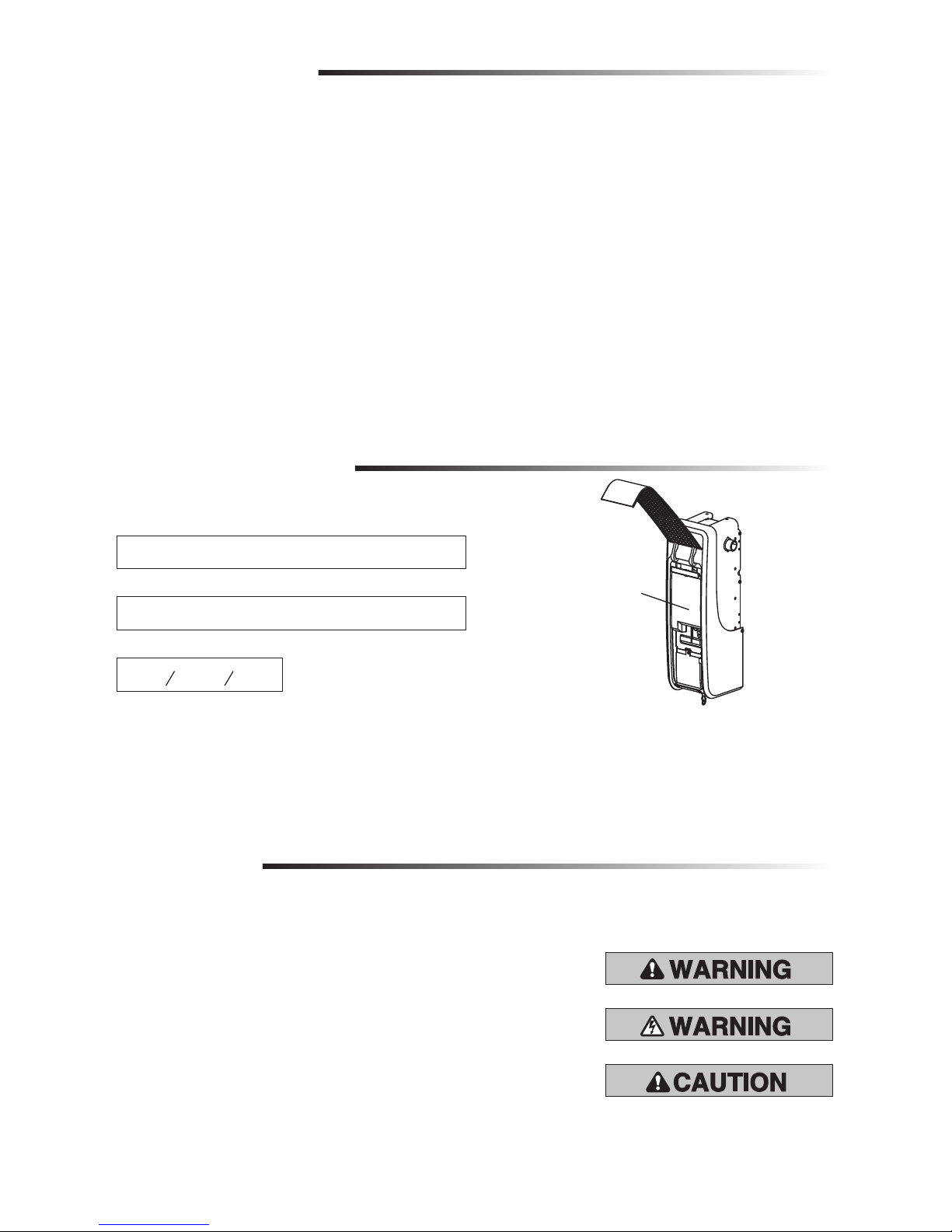
myQ® Serial Number
When you see these Safety Symbols and Signal Words on the following pages, they
will alert you to the possibility of serious injury or death if you do not comply with the
warnings that accompany them. The hazard may come from something mechanical or
from electric shock. Read the warnings carefully.
When you see this Signal Word on the following pages, it will alert you to the possibility of
damage to your garage door and/or the garage door opener if you do not comply with the
cautionary statements that accompany it. Read them carefully.
Mechanical
Electrical
Safety Symbol and Signal Word Review
This garage door opener has been designed and tested to offer safe service provided it is installed, operated, maintained and tested in
strict accordance with the instructions and warnings contained in this manual.
Table of Contents
myQ SERIAL NUMBER 2
UNATTENDED OPERATION 2
INTRODUCTION 2
Safety Symbol and Signal Word Review ...... 2
Planning ........................................................ 4
Before You Connect with Your Smartphone 5
Preparing Your Garage Door ........................ 6
Tools Needed ................................................ 6
Carton Inventory ........................................... 7
Included Accessories .................................... 7
Hardware ....................................................... 7
Additional Items You May Need ................... 7
ASSEMBLY 8
Attach the Collar to the
Garage Door Opener ..................................... 8
Attach Mounting Bracket to
Garage Door Opener ..................................... 8
ASSEMBLY 9
Wiring Diagram ............................................. 9
INSTALLATION 10
Position and Mount the
Garage Door Opener ................................... 10
Attach the Emergency Release Rope
and Handle .................................................. 11
Install Automatic Door Lock ....................... 11
Attach the Cable Tension
Monitor (Required) ..................................... 12
Install the Door Control
(Smart Control Panel®) ............................... 13
Install myQ Remote LED Light ................... 14
Install the Protector SystemTM ................... 15
Connect Power ............................................ 18
Install the Battery Backup ........................... 19
ADJUSTMENT 20
Program the Travel ..................................... 20
Test the Safety Reversal System ................ 21
Test the Protector SystemTM ...................... 21
Test Cable Tension Monitor ........................ 22
Test Automatic Door Lock .......................... 22
To Open the Door Manually ........................ 22
OPERATION 23
Using Your Garage Door Opener ................ 24
Connect with Your Smartphone ................. 25
Using the Door Control ............................... 26
PROGRAMMING 27
E960M Premium+ Remote Control ............ 27
Reprogramming myQ® Remote
LED Light..................................................... 28
To Erase the Memory .................................. 28
MAINTENANCE 29
Care of Your Garage Door Opener .............. 29
TROUBLESHOOTING 30
Diagnostic Chart .......................................... 30
Additional Troubleshooting ......................... 31
REPAIR PARTS 32
Installation Parts ......................................... 32
Garage Door Opener Assembly Parts ......... 33
ACCESSORIES 34
WARRANTY 35
Date of Purchase:
Write down the following information for future reference:
Product S/N:
myQ® Serial Number:
Serial Numbers
Unattended Operation
The Timer-to-Close (TTC) feature, the myQ® Smartphone Control app, and myQ® Garage Door are examples of unattended close and are
to be used ONLY with sectional doors. Any device or feature that allows the door to close without being in the line of sight of the door is
considered unattended close.
myQ Remote LED Light must be installed to enable use of Timer To Close or myQ Smartphone Control of the door.
Page 4
4
Introduction
Planning
Survey your area to see if any of the conditions below apply to your installation.
Depending on your requirements, additional materials may be required.
THIS DOOR OPENER IS COMPATIBLE WITH:
• Doors that use a torsion bar and springs. The torsion bar must be 1" (2.5 cm)
diameter. NOT compatible with reverse wound drums.
• 3-4" (8-12 cm) drums good for 130 kg / 230 kg with installation of The Protector
System™ (Safety IR Beams).
• Standard lift sectional doors up to 10 ft. (3.0 m) high.
• Standard lift sectional door up to 18 ft (5.5 m) wide.
• Standard lift sectional door max area up to 180 sq. ft (16.5m2).
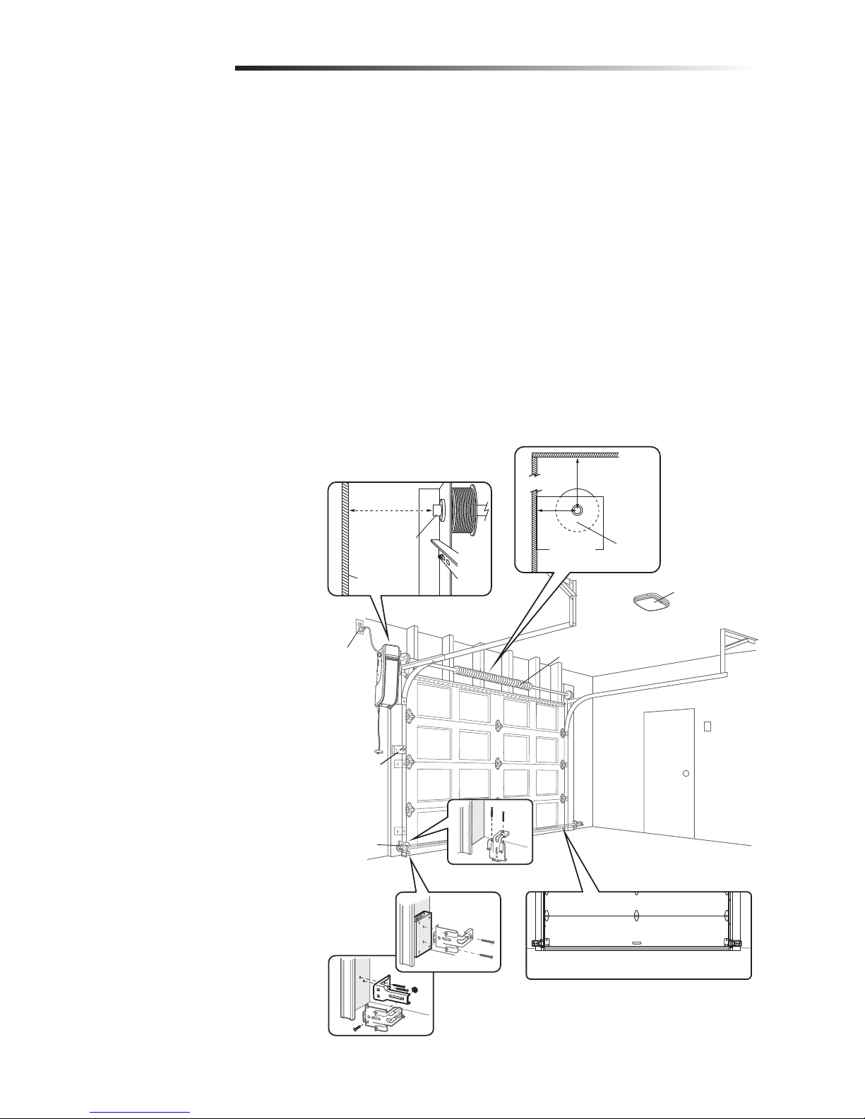
Review or inspect proposed installation area. The door opener can be installed on the left
or right side of door. Select the side that meets the requirements listed below.
a. Must have minimum of 2.5" (6.4 cm) between the wall and the center of the torsion
bar.
b. Must have minimum of 3" (7.6 cm) between the ceiling and the center of torsion bar.
c. Must have minimum of 8.5" (21.6cm) between the side wall (or obstruction) and the
end of torsion bar.
d. The torsion bar must extend at least
1.5" (3.81 cm) past the bearing.
This may vary depending on your
installation requirements.
e. An electric outlet is required within
6ft. (1.83 m) of the installation area.
If outlet does not exist, contact a
qualified electrician.
f. Depending upon building
construction, extension brackets or
wood blocks may be needed to install
safety reversing sensors and cable
tension monitor.
g. Alternate floor mounting of the
safety reversing sensors will require
hardware (not provided).
h. Check the seal on the bottom of the
door. Any gap between the floor and
the bottom of the door must not
exceed 1/4 inch (6 mm). Otherwise,
the safety reversal system may not
work properly.
NOTE: Inspect the torsion bar while the
door is raised and lowered. It is important
that there is no noticeable movement up
and down or left and right. If the movement
is not corrected, the life of the garage door
opener will be greatly reduced.
a
b
h
c
d
e
f
g
Torsion
bar
2.5"
(6.4 cm)
3"
(7.6 cm)
Wall or
obstruction
Torsion bar
8.5"
(21.6cm)
Safety
reversing
sensor
myQ® Remote
LED Light
Automatic
door lock
Door spring
Page 5
5
Before You Connect with Your Smartphone
Introduction
Monitor and control your garage door away from home using the myQ® app.
BEFORE YOU BEGIN:
You will need:
• Wi-Fi enabled smartphone, tablet or laptop
• Broadband Internet Connection
• Wi-Fi signal in the garage (2.4 Ghz, 802.11b/g/n required)
• Password for your home network (router's main account, not guest network)
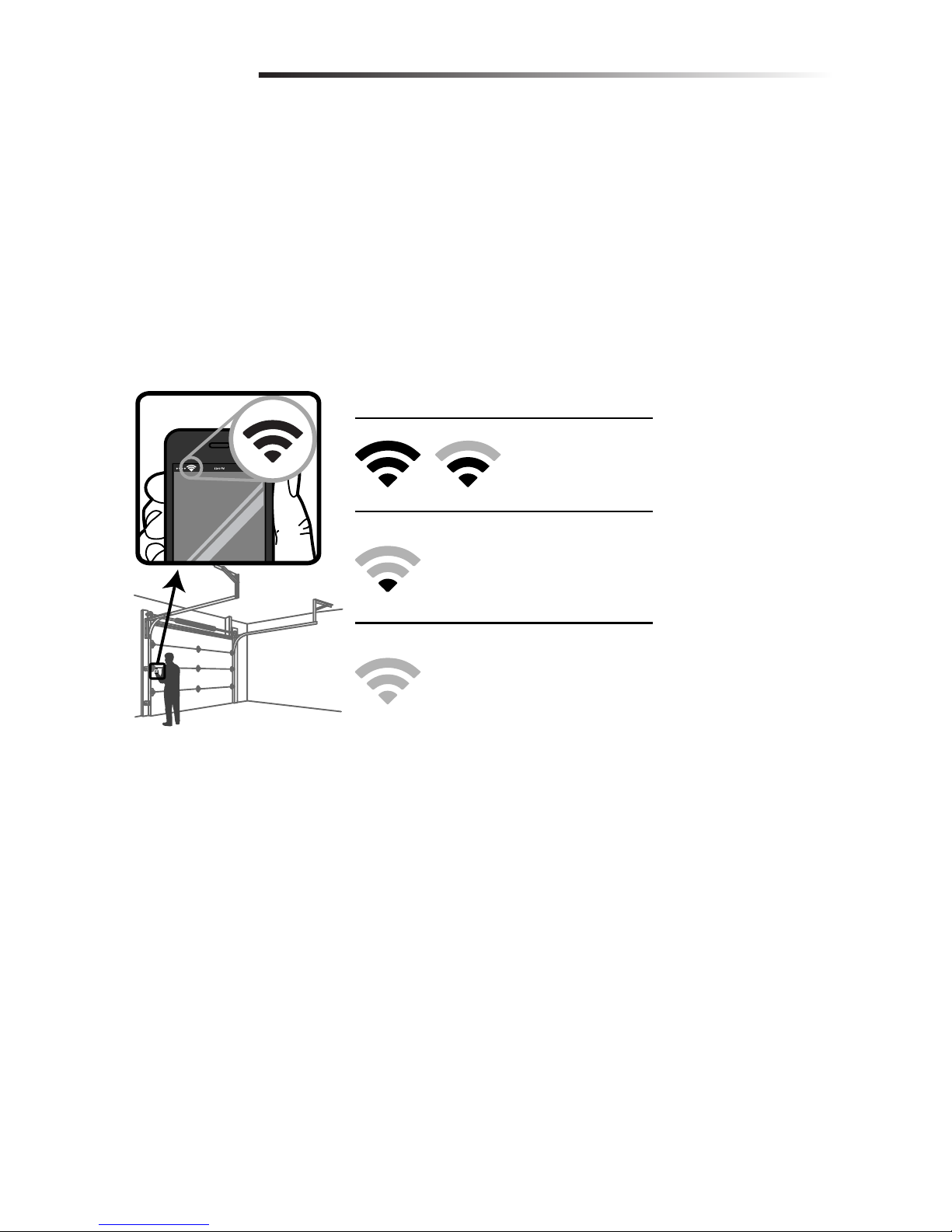
TEST THE WI-FI SIGNAL STRENGTH
Make sure your mobile device is connected to your Wi-Fi network. Hold your mobile
device in the place where your garage door opener will be installed and check the Wi-Fi
signal strength.
See page 24 to connect the garage door opener to a mobile device.
Check Signal Strength. If you see:
Wi-Fi signal is strong.
The garage door
opener will connect to
your Wi-Fi network.
Wi-Fi signal is weak.
The garage door opener may connect
to your Wi-Fi network. If not, try one
of the options below to improve the
Wi-Fi signal:
No Wi-Fi signal.
The garage door opener will not be
able to connect to your Wi-Fi network.
Try one of the options below to
improve the Wi-Fi signal:
• Move your router closer to the garage door opener to
minimize interference from walls and other objects
• Buy a Wi-Fi range extender
Page 6
6
Introduction
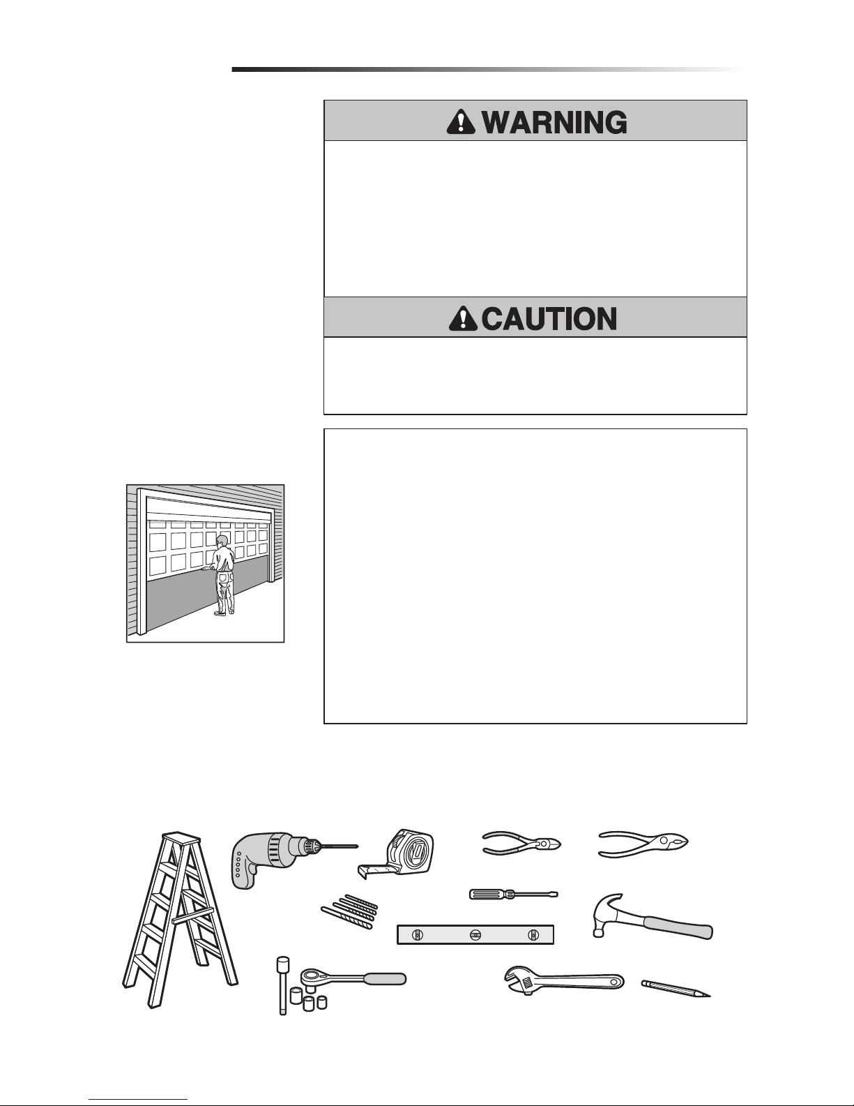
Preparing Your Garage
Door
BEFORE YOU BEGIN:
• Disable locks.
• Remove any ropes connected to the
garage door.
Complete the following test to make sure
the garage door is balanced and is not
sticking or binding:
1. Lift the door halfway up. Release
the door. If balanced, it should stay
in place, supported entirely by its
springs.
2. Raise and lower the door to check for
binding or sticking.
If your door binds, sticks, or is out of
balance, call a trained door systems
technician.
To prevent damage to garage door and opener:
• ALWAYS disable locks BEFORE installing and operating the opener.
• ONLY operate garage door opener at 240V mains to avoid malfunction and
damage.
To prevent possible SERIOUS INJURY or DEATH:
• ALWAYS call a trained door systems technician if garage door binds, sticks, or is
out of balance. An unbalanced garage door may NOT reverse when required.
• NEVER try to loosen, move or adjust garage door, door springs, cables, pulleys,
brackets or their hardware, ALL of which are under EXTREME tension.
• Disable ALL locks and remove ALL ropes connected to garage door BEFORE
installing and operating garage door opener to avoid entanglement.
• This opener system is equipped with an unattended operation feature. The door
could move unexpectedly. NO ONE SHOULD CROSS THE PATH OF THE MOVING
DOOR.
Tools Needed
During assembly, installation and adjustment of the garage door opener, instructions will
call for hand tools as illustrated below.
Pliers
Wire Cutters
Claw Hammer
Screwdriver
Adjustable End Wrench
1/4", 5/16", and 3/8" Sockets
and Wrench with 6" Extension
Drill
Tape Measure
Stepladder
Pencil
5/32", 3/16", 5/16"
and 3/4" Drill Bits
Level
Sectional Door
SPECIFICATIONS
Volts ............................................240 Vac - 50 Hz, ONLY
Current .....................................................1.5 AMP
LED Light Current (independently powered) ........................0.2 AMPS
Power .................................................... 150 Watts
R/T 4 ...................................................... minutes
Rated Load ................................................... 10Nm
Max door height ....................up to 4.2 m (with max. door area 16.5m2)
Max door width.................... up to 5.5 m (with max. door area 16.5m2)
Max door area................................................16.5 m2
Max door weight ( 3 & 4 inch drum)...... 130 kg / 230 kg with installation of The
Protector System™ (Safety IR Beams).
Max lift under spring tension ...................................... 20 kg
Page 7
7
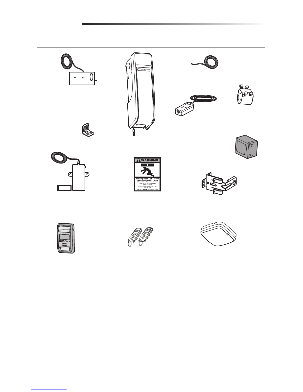
Carton Inventory
If anything is missing, carefully check the packing material.
Introduction
Automatic Garage Door Lock Model ???
with 2-Conductor White and White/Black
Bell Wire with Connector
NOTE: Older model 24V door locks
are incompatible
2 Conductor Bell Wire
White and White/Red
Garage Door Opener
Cable Tension Monitor with
2-Conductor Green/White Bell Wires
Mounting Bracket
Collar with
Set Screws
Safety Reversing Sensor Bracket (2)
The Protector System
®
(2) Safety Reversing Sensors
(1 Sending Sensor and
1 Receiving Sensor) with
2-Conductor White and
White/Black Bell Wire attached
Safety Labels
and Literature
Battery
Hardware
Additional Items You May Need
Extension brackets (Model 041A5281-1)
or wood blocks: Depending upon garage
construction, extension brackets or wood
blocks may be needed to install the safety
reversing sensor.
Fastening hardware: Alternate floor
mounting of the safety reversing sensor
will require hardware not provided.
90˚ connector for cable conduit or flex
cable adapter: Required for permanent
wiring.
Screw #10-32 (2)
Screw 14-10x2" (4)
Handle
Rope
Screw 1/4"-20x1/2" (2)
Drywall Anchor (Screw-In) (2)
Screw 8-32x1" (2)
Screw 6ABx1-1/4" (2)
Drywall Anchor (2)
Screw 6-32x1" (2)
Carriage Bolt 1/4"-20x1/2" (2)
Wing Nut 1/4"-20 (2)
REMOTE LIGHT HARDWARE:
myQ® Remote LED Light Model 827AU
Drywall Anchor (Screw-In) (2)
Screw #6x1" (2)
Included Accessories
4-Button Premium+
Remote Control
Model E960M (2)
MyQ
®
Remote LED Light
Model 827AU
(Garage Door Opener Light)
with Hardware Bag
Automatic Garage Door Lock Model ???
with 2-Conductor White and White/Black
Bell Wire with Connector
NOTE: Older model 24V door locks
are incompatible
2 Conductor Bell Wire
White and White/Red
Garage Door Opener
Cable Tension Monitor with
2-Conductor Green/White Bell Wires
Mounting Bracket
Collar with
Set Screws
Safety Reversing Sensor Bracket (2)
The Protector System
®
(2) Safety Reversing Sensors
(1 Sending Sensor and
1 Receiving Sensor) with
2-Conductor White and
White/Black Bell Wire attached
Safety Labels
and Literature
Smart Control Panel
®
Model 880AUW
Battery
Page 8
8
Set
Screws
Collar
Motor
Shaft
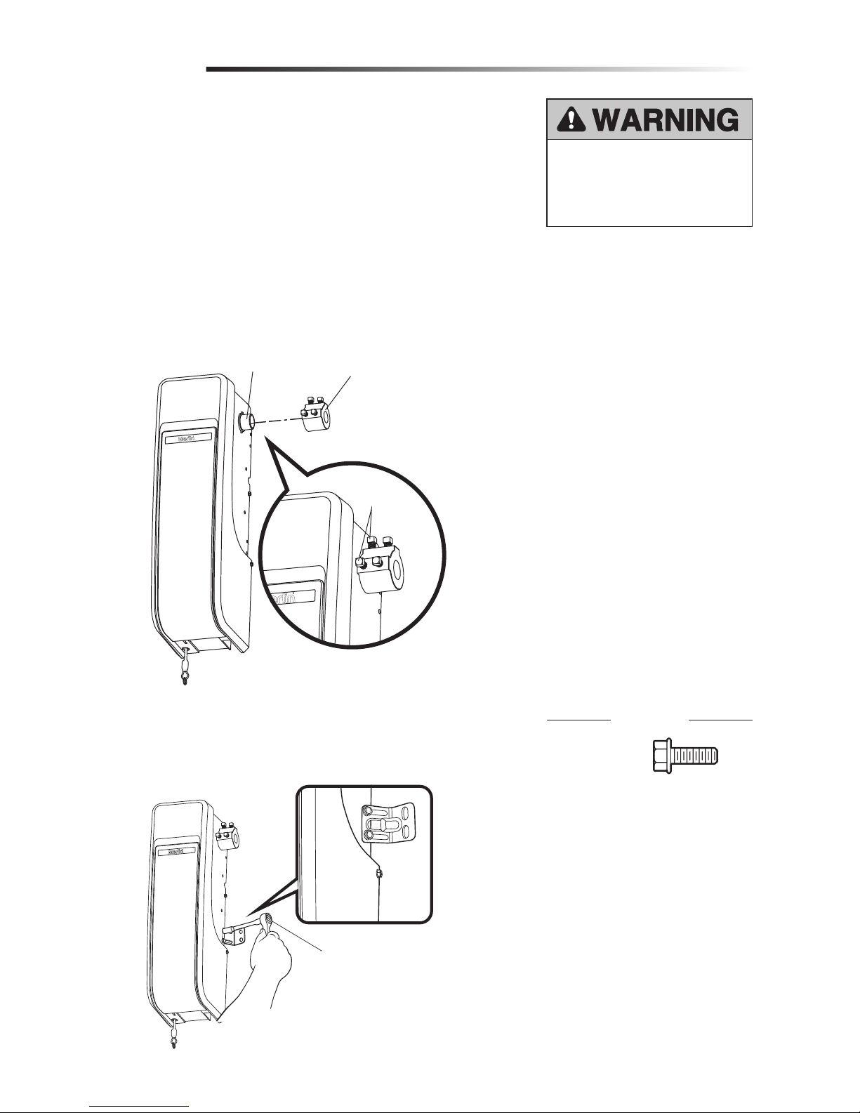
The garage door opener can be installed on either side of the door (see Planning section
page 4). The illustrations shown are for installation on the left side.
1. Loosen the set screws.
2. Attach collar to the garage door opener motor shaft. The side of the collar with the
larger hole should be placed on the motor shaft. Ensure that the collar is seated all
the way on motor shaft until stop is reached.
3. Position the collar so the screws are facing out and are accessible when attached to
the torsion bar.
4. Securely tighten the 2 square head set screws closest to the motor shaft by turning
the screws 1/4 - 1/2 turn after making contact with the motor shaft.
Attach the Collar to the Garage Door Opener
Assembly
1
To prevent possible SERIOUS INJURY
or DEATH, the collar MUST be properly
tightened. The door may NOT reverse
correctly or limits may be lost due to
collar slip.
Attach Mounting Bracket to Garage Door Opener
2
1. Loosely attach slotted side of mounting bracket to the same side of the garage door
opener as the collar, using screws provided.
NOTE: Do not tighten screws until instructed.
Socket Wrench
HARDWARE
Screw
#10-32 (2)
Page 9
9
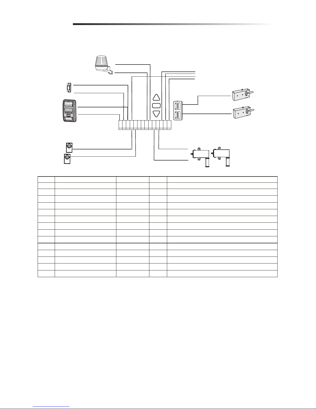
Wiring
1 2 3 4 5 6 7 8 9 10 1112 1314
Flasher
Contact Closure
E-Serial
Safety Sensor
Door Lock
Max Qty - 2 supported
Cable Tension Monitor
Max Qty-2 supported
Open/Stop/Close
wall station
Pin#
Function
Color
Polarity
Comment
1
E-serial push button
Green
+
For Encrypted serial communication (Wall control)
2
Push Button
Red
+
Dry contact (contact closure)
3
Ground
White
-
Wall controls (dry contact and E serial)
4
Ground
White
-
IR sensors
5
IR-Sensor
Grey
+
IR sensors
6
Green
+
7
Green
-
8
Flasher
Black/Gray
+
Flashing Light output
9
Flasher & OCS Ground
White
-
Flashing Light ground
10
Cable tension monitor
Green
+
Connection for a cable tension monitor
11
Cable tension monitor
Green
-
Connection for a cable tension monitor
12
OCS wall station - Open
Green
Open/Stop/Close wall station
13
OCS wall station -Stop
Green
Open/Stop/Close wall station
14
OCS wall station - Close
Green
Open/Stop/Close wall station
CONTROL PANEL - (located under front cover of the opener. Lift to access)
Page 10
10
Set screws
(Torsion bar)
Bearing
Plate
Shaft
Collar
Torsion Bar
.25" (.6 cm) min.
space between
bearing and
shaft collar
Mounting Bracket
Screws 14-10 x 2"
Installation
HARDWARE
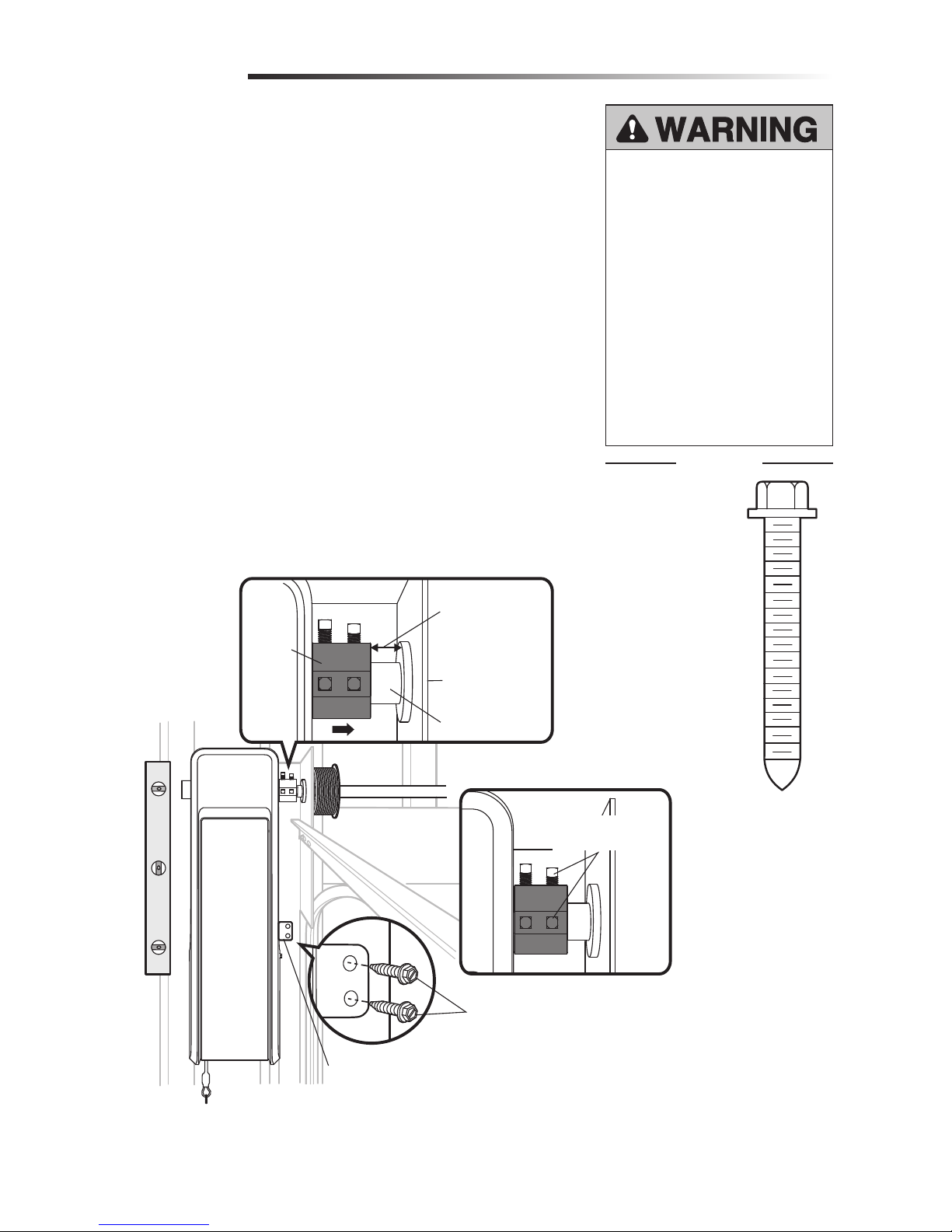
Position and Mount the Garage Door Opener
1
NOTE: For additional mounting options refer to the accessories on page 34.
1. Close the garage door completely.
2. Slide the garage door opener onto the end of the torsion bar. If the torsion bar is too
long or damaged, you may need to cut the torsion bar.
Ensure the collar does NOT touch the bearing.
3. Use a level to position and vertically align the garage door opener. Verify the
mounting bracket is located on a solid surface such as wood, concrete or door/flag
bracket. If installing on drywall, the mounting bracket MUST be attached to a stud.
4. When the garage door opener is properly aligned, mark the mounting bracket holes.
If necessary, tighten collar screws on the torsion bar to hold garage door opener in
place while marking holes.
NOTE: The garage door opener does not have to be flush to wall.
5. Remove the garage door opener from torsion bar. Drill 3/16 inch pilot holes at the
marked locations. Drill through metal door rail plates if necessary.
6. Slide the garage door opener back onto the torsion bar until pilot holes align with
bracket.
7. Tighten the 2 square head set screws on the torsion bar. For a hollow torsion bar,
tighten screws 3/4 - 1 full turn after making contact with the bar. For a solid shaft
torsion bar, tighten screws 1/4 - no more than 1/2 turn after making contact with
the shaft. If installing on a keyed torsion bar, DO NOT tighten the screws into the
keyway.
8. Secure the mounting bracket to the wall and to the garage door opener. Use the
14-10 x 2" screws to secure the mounting bracket to the wall.
To prevent possible SERIOUS INJURY
or DEATH:
• Concrete anchors MUST be used if
mounting bracket into masonry.
• NEVER try to loosen, move or
adjust garage door, springs,
cables, pulleys, brackets or their
hardware, ALL of which are under
EXTREME tension.
• ALWAYS call a trained door
systems technician if garage door
binds, sticks or is out of balance.
An unbalanced garage door might
NOT reverse when required.
• Garage door opener MUST be
mounted at a right angle to the
torsion bar to avoid premature
wear on the collar.
Screw
14-10 x 2" (2)
Page 11
11
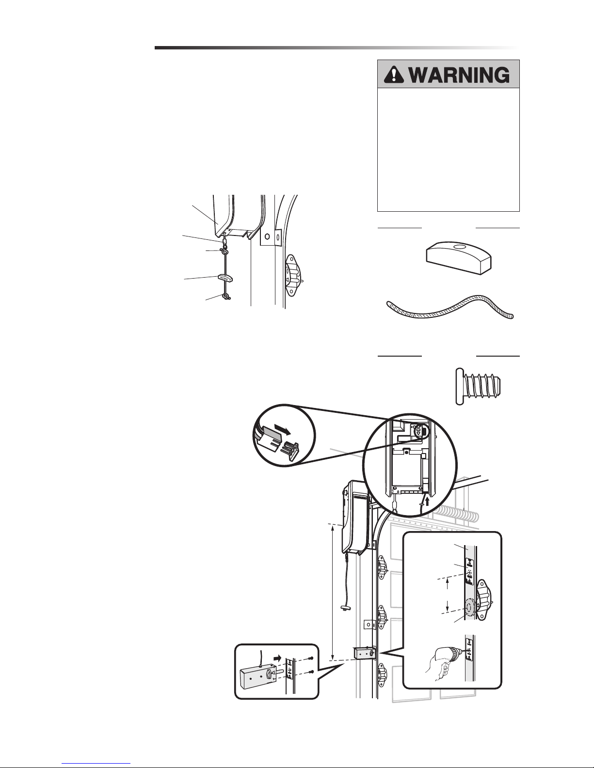
Attach the Emergency Release Rope and Handle
Install the Automatic Door Lock
2
3
1. Insert one end of the emergency release rope through the handle. Make sure that
“NOTICE” is right side up. Secure with an overhand knot at least 1" (2.5 cm) from
the end of the rope to prevent slipping.
2. Insert the other end of the emergency release rope through the hole in the trolley
release arm. Mount the emergency release within reach, but at least 6 feet (1.83 m)
above floor, avoiding contact with vehicles to prevent accidental release and secure
with an overhand knot.
NOTE: If it is necessary to cut the rope, heat seal the cut end with a match or lighter to
prevent unraveling.
Installation
The automatic garage door lock (model 841ANZ) is used to prevent the door from
being manually opened once the door is fully closed, see Accessories page 34
Garage Door
Opener
Emergency
Release Cable
Overhand
Knot
Overhand
Knot
Emergency
Release Handle
To prevent possible SERIOUS INJURY
or DEATH from a falling garage door:
• If possible, use emergency release
handle to disengage door ONLY when
garage door is CLOSED. Weak or
broken springs or unbalanced door
could result in an open door falling
rapidly and/or unexpectedly.
• NEVER use emergency release handle
unless garage doorway is clear of
persons and obstructions.
HARDWARE
Screw 1/4"20x1/2" (2)
Rope
Handle
HARDWARE
10 feet (3.05 m)
max.
3" (7.6 cm)
Door Track
Roller
Lock
Template
1
2
3
4
5
6
NOTE: Older model 24 V door locks are
incompatible.
1. The lock must be mounted within
10 ft. (3.05m) of door opener If
possible, mount on same side as
door opener. The third roller from the
bottom is ideal for most installations.
2. Ensure rail surface is clean and attach
the lock template to the track so
that the bolt hole is approximately 3"
(7.6cm) from the center of a door
roller.
3. Drill holes as marked on the template.
4. Fasten automatic door lock to
the outside of the door track with
hardware provided.
5. Run bell wire up wall to door opener.
Use insulated staples to secure wire
in several places. Insert wire through
the bottom of the door opener.
6. Plug the connector into either plug in
the door opener.
A secondary door lock can be installed on
the opposite side of the door following the
instructions above.
Page 12

12
HARDWARE
Attach the Cable Tension Monitor (Required)
4
Drum
Cable
To insert or
release wire,
push in tab with
screwdriver tip
(to cable tension monitor)
(to garage door opener)
Refer to Wiring
Diagram on page 9
Wall
2"-6"
(51 - 153mm)
Approx. 3/4" (19 mm)
Cable
Tension
Monitor
Cable Tension
Monitor Roller
1/8"-1/4"
(3-6 mm)
Installation
The cable tension monitor MUST be
connected and properly installed before
the garage door opener will move in the
down direction.
The cable tension monitor detects ANY
slack that may occur in the cables and
will reverse the door, eliminating service
calls.
SIDE VIEW
Screws
#8-32x1" (2)
Drum
Cable Tension
Monitor Roller
Screw
14-10x2" (2)
NOTE: The cable tension monitor is shipped for left side installation. It is recommended
that the cable tension monitor be installed on the same side of the door as the door
opener. For right side installation, remove the snap-ring holding the roller in place and
reassemble it on the opposite side of the cable tension monitor.
1. Make sure the door cable is approximately 3/4" (19 mm) from the mounting surface.
Door adjustments or shimming may be required to achieve proper depth for the door
cable.
2. Position the cable tension monitor so the roller is 2"-6" (51 - 153mm) from the drum
and the roller extends 1/8"-1/4" (3 - 6mm) past the cable. Make sure cable tension
monitor is located over a wood support member and the roller is free from any
obstructions.
NOTE: There must be no obstructions in the installation area that prevent the cable
tension monitor from closing completely when slack is detected.
3. Mark and drill 3/16" pilot holes for screws (pilot holes are not required for anchors).
4. Attach the cable tension monitor to the wall using the hardware provided. Make sure
that the roller is on top of the cable.
5. Run bell wire to door opener. Use insulated staples to secure wire.
6. Connect bell wire to the green quick-connect terminals on the door opener (polarity
is not important).
NOTE: Cable must have tension through entire door travel. Make sure there is no
slack in cable on opposite side of door during normal operation. If slack occurs
during door travel, adjust cables as required.
A second cable tension monitor may be installed for additional security. When two cable
tension monitors are installed, the door will not move in the down direction or will reverse
if one of the monitors detects slack or is disconnected.
If one of the cable tension monitors is removed, unplug both monitors from the opener.
Then plug in the monitor you wish to use and unplug and plug in the opener three times
to relearn the monitor to the opener.
Page 13

13
Install door control within sight of garage door, out of reach of small children at a
minimum height of 5 feet (1.5 m) above floors, landings, steps or any other adjacent
walking surface, and away from ALL moving parts of door.
Your garage door opener is compatible with up to 2 Smart Control Panels or 4 of any
other Security+ 2.0® door controls. NOTE: Older Merlin door controls and third party
products are not compatible.
For gang box installations it is not necessary to drill holes or install the drywall anchors.
Use the existing holes in the gang box.
1. Strip 7/16" (11 mm) of insulation from one end of the wire and separate the wires.
2. Connect one wire to each of the two screws on the back of the door control. The
wires can be connected to either screw. PRE-WIRED INSTALLATIONS: Choose
any two wires to connect, but make note of which wires are used.
3. Mark the location of the bottom mounting hole and drill a 5/32" (4 mm) hole.
4. Install the bottom screw, allowing 1/8" (3 mm) to protrude from the wall.
5. Position the bottom hole of the door control over the screw and slide down into
place.
6. Lift the push bar up and mark the top hole.
7. Remove the door control from the wall and drill a 5/32" (4 mm) hole for the top
screw.
8. Position the bottom hole of the door control over the screw and slide down into
place. Attach the top screw.
9. Run the white and red/white wire from the door control to the garage door opener.
Attach the wire to the wall and ceiling with the staples (not applicable for gang box
or pre-wired installations). Do not pierce the wire with the staple as this may cause
a short or an open circuit.
10. Connect the wire to the red and white terminals on the garage door opener. The
wires can be connected to either terminal.
11. Fasten the warning placard to the wall next to the door control.
NOTE: DO NOT connect the power and operate the garage door opener at this time. The
door will travel to the full open position but will not return to the close position until the
safety reversing sensors are connected and properly aligned. See page 15.
Install the Door Control (Smart Control Panel)
5
Installation
To prevent possible SERIOUS INJURY or
DEATH from electrocution:
• Be sure power is NOT connected
BEFORE installing door control.
• Connect ONLY to 7-28 VOLT low
voltage wires.
To prevent possible SERIOUS INJURY or
DEATH from a closing garage door:
• Install door control within sight of
garage door, out of reach of small
children at a minimum height of 5 feet
(1.5 m) above floors, landings, steps
or any other adjacent walking surface,
and away from ALL moving parts of
door.
• NEVER permit children to operate or
play with door control push buttons or
remote control transmitters.
• Activate door ONLY when it can be
seen clearly, is properly adjusted,
and there are no obstructions to door
travel.
• ALWAYS keep garage door in sight
until completely closed. NEVER permit
anyone to cross path of closing garage
door.
HARDWARE
To insert or
release wire,
push in tab with
screwdriver tip
7/16" (11 mm)
Screw 6ABx1-1/4" (Standard installation) (2)
Screw 6-32x1"
(pre-wired) (2)
Drywall
Anchors (2)
Insulated Staples
(Not shown)
(to garage door opener)
(to door control)
Refer to Wiring
Diagram on page 9
Page 14

14
Screws
Light Lens
Drywall
Anchors
6-1/8" (15.6 cm)
Cord Retainer
Channel
The myQ Remote LED Light is designed to
plug directly into a standard 240V outlet.
Select an appropriate location on the
ceiling or wall to mount the light within 6
feet (1.83 m) of an electrical outlet so that
the cord and light are away from moving
parts.
NOTE: If installing light on drywall and a
ceiling joist cannot be located, use drywall
anchors provided. No pilot hole is required
for drywall anchors.
1. Drill pilot holes 6-1/8" (15.6 cm) apart
if mounting to joist.
OR
Screw in drywall anchors 6-1/8"
(15.6cm) apart if mounting to
drywall.
2. Determine the length of power cord
needed to reach the nearest outlet.
Wind any excess cord around cord
retainer on the top side of the light
base. Route the cord through the
channel so the light mounts flush.
3. Open the light lens.
4. Mount the light with the screws
provided.
5. Close the light lens.
6. Plug in the light to the outlet.
NOTE: The LED light is very bright.
DO NOT stare at the light while on a
ladder.
Your garage door opener remote light has
already been programmed at the factory to
operate with your opener. Any additional or
replacement remote lights will need to be
programmed.
Install myQ® Remote
LED Light
6
Installation
IMPORTANT INSTALLATION INSTRUCTIONS
To reduce the risk of SEVERE INJURY or DEATH:
•. DO NOT alter the plug.
•. myQ Remote LED Light is intended for ceiling or wall mount
and indoor applications ONLY.
Drywall Anchor (screw-in) (2)
HARDWARE
Screw #6x1" (2)
Page 15

15
The safety reversing sensor must be connected and aligned correctly before the
garage door will move in the down direction. This is a required safety device and
cannot be disabled.
NOTE: Merlin recommends to install the safety reversing sensors on each installation.
For use of myQ or Timer-To-Close features the installation of the safety reversing
sensors are required.
IMPORTANT INFORMATION ABOUT THE SAFETY REVERSING SENSOR
When properly connected and aligned, the safety reversing sensor will detect an obstacle
in the path of its electronic beam. The sending sensor (with an amber indicator light)
transmits an invisible light beam to the receiving sensor (with a green indicator light).
If an obstruction breaks the light beam while the door is closing, the door will stop and
reverse to full open position, and the opener lights will flash 10 times.
The sensors must be installed inside the garage so that the sending and receiving sensors
face each other across the door, no more than 3.9 inches (10 cm) above the floor. Either
can be installed on the left or right of the door as long as the sun never shines directly into
the receiving sensor lens.
The mounting brackets are designed to clip onto the track of sectional garage doors
without additional hardware.
If it is necessary to mount the sensors on the wall, the brackets must be securely fastened
to a solid surface such as the wall framing. Extension brackets (see accessories) are
available if needed. If installing in masonry construction, add a piece of wood at each
location to avoid drilling extra holes in masonry if repositioning is necessary.
The invisible light beam path must be unobstructed. No part of the garage door (door
tracks, springs, hinges, rollers or other hardware) may interrupt the beam while the door
is closing.
Be sure power is NOT connected to the
garage door opener BEFORE installing
the safety reversing sensor.
To prevent SERIOUS INJURY or
DEATH from a closing garage door:
• Correctly connect and align the
safety reversing sensor. This
required safety device MUST NOT
be disabled.
• Install the safety reversing sensor
so beam is NO HIGHER than 3.9"
(10 cm) above garage floor.
Installation
Safety Reversing
Sensor
3.9" (10 cm) max.
above floor
Safety Reversing
Sensor
3.9" (10 cm) max.
above floor
Invisible Light
Beam Protection
Area
Install the Protector SystemTM
7
Facing the door from inside the garage.
Page 16

16
Installation
NOTE: This accessory must be used for all myQ installations and
all other installations where the closing force as measured on the
bottom of the door is over 400 N (40 kgf).
SPECIAL NOTE: Merlin strongly recommends that The Protector
SystemTM be installed on all garage door openers.
SAFETY BEAMS: By installing Safety Beams, an open door is
prevented from closing if a person or object is located in the beam
area. If the door is already closing, it will return to the open position.
A closed door is not prevented from opening.
If the Protector System
TM
is installed and needs to be removed, the
opener will need to be reprogrammed .
Assembly Process:
The Safety Beams are supplied preassembled, complete with two
sensors, wiring and wall brackets.
Install the mounting brackets and sensors to either side of the inside
of the garage door, and at a height of no greater than 100 mm off
the garage floor.
The brackets are designed to be used for Wall or Floor fixing, with a
variety of hole combinations to achieve the desired results (fig 1).
Drill the required holes and install the brackets with wall plugs and
screws provided. Ensure they do not obstruct the door movement.
Align the Safety Beams to face each other and tighten if necessary.
The wiring should exit from the bottom of the housing to maintain
the correct IP rating and continued operation.
One sensor is a Sending Eye , the other is a Receiving Eye. Try to
avoid positioning these in direct sunlight as this may interfere with
the operation of the beams.
Install Cabling:
Run both sets of Safety Beam cables up the door tracks, across the
door header and back to the Power Head (see fig 2 & 4).
Clean the contact area with alcohol wipes (provided) and secure the
self-adhesive Cable Mounts to the rails. Attach the cable with cable
ties.
Ensure the cable is well supported and does not interfere or get
damaged by movement of the door panels or spring hardware.
INSTALLING THE BRACKETS
Be sure power to the opener is disconnected. Install and align the brackets so the safety reversing sensors will face each other across
the garage door, with the beam no higher than 3.9" (10 cm) above the floor. Choose one of the following installations.
g.1
Cable Tie Mount
at the top
Cable Tie Mount
at the middle
Cable Tie Mount
close to the Beam
100 mm Cardboard
template
Beam and Bracket
assembly
view 1
view 2
g.2
To prevent entrapment, install Safety
Beams no higher than 100 mm above
the floor.
Disconnect power to the garage door
opener before installing Safety Beams.
Page 17

17
Installation
INSTALL THE PROTECTOR SYSTEMTM (CONTINUED)
Connect cable to the Opener:
Disconnect the mains Power from the Opener.
At the Powerhead Control Panel located under the front cover of the
opener. Lift to access the “External Accessory Terminal Block”.
Twist both WHITE wires together and both GREY wires together.
Connect the WHITES to the white mark screw terminal of the 2-way
connector, and the GREYS to the grey mark screw terminal (see fig 3).
Push the 2-way connector into the control panel quick release terminals B
& C (see wiring diagram on page 9).
Ensure the white wires go to B and the grey wires go to C.
Loop and secure the excess cabling above the opener assembly.
Test the Safety Beam operation:
Remove all obstacles from the path of the door. Connect the mains Power
to the opener.
1. Using a remote control, check the Opener operates in both directions.
2. Obstruct the beams with the door fully OPEN, the door should not
move and the Courtesy light will Flash 10 times.
3. Obstruct the beams with the door travelling DOWN, the door should
STOP and return to the UP position. The Courtesy light will Flash 10
times.
4. Obstruct the beams with the door travelling UP, the door should
continue to the OPEN position.
Status indicators on the Safety Beams:
Normal Operation --Low standby Mode --
Safety Beams misaligned-Safety Beams obstructed--
For further diagnostics refer to the TROUBLESHOOTING section on page
30.
Emergency Overide:
NOTE: The door can't be closed using the myQ app if an obstruction of
Safety Beam failure has occurred.
However, if needed, the door can be closed by using the programmed
button of a Smart Control Panel (880AUW), Keyless Entry Keypad
(E840M) or the Control button located on the bottom of the opener.
Follow the process below:
With the door open Press the programmed button once and release.
Press and “HOLD” the button again, and continue to HOLD untl the door
has completely closed.
NOTE: If the button is released at any point during the downward
movement, the door will stop and return to the OPEN position. In this
case repeat the previous process again. The “DOOR CLOSE” process
will need to be performed each time the door needs to be CLOSED,
until the obstruction is removed or repairs are made to the Safety Beam
System.
Refer to Wiring
Diagram on
page 9
CABLE END
3 X CABLE TIE MOUNT
WITH CABLE TIE
OPENER
BEAM 1
BEAM 2
1 X 2-WAY CONNECTOR
WITH LEADS AND CABLE
COLOUR MARK
3 X CABLE TIE MOUNT
WITH CABLE TIE
White x2
Grey x2
g. 3
Page 18

18
Connect Power
8
Installation
To avoid installation difficulties, do not
run the garage door opener at this time.
To reduce the risk of electric shock, your
garage door opener has a grounding type
plug with a third grounding pin. This plug
will only fit into a grounding type outlet. If
the plug doesn’t fit into the outlet you have,
contact a qualified electrician to install the
proper outlet.
CONNECT POWER
1. Plug in the garage door opener into a
grounded outlet.
2. DO NOT run garage door opener at
this time.
To prevent possible SERIOUS INJURY or DEATH from electrocution or fire:
• Garage door installation and wiring MUST be in compliance with ALL local electrical
and building codes.
• NEVER use an extension cord, 2-wire adapter or change plug in ANY way to make it
fit outlet. Be sure the opener is grounded.
Page 19

19
To reduce the risk of FIRE or INJURY
to persons:
• Disconnect ALL electric and battery
power BEFORE performing ANY
service or maintenance.
• Use ONLY Merlin part #041A6357-2
for replacement battery.
• DO NOT dispose of battery in fire.
Battery may explode. Check with local
codes for disposal instructions.
ALWAYS wear protective gloves and
eye protection when changing the
battery or working around the battery
compartment.
When in Battery Backup mode, myQ® Smartphone Control and wireless myQ devices
will be disabled. In battery backup mode, the automatic garage door lock will unlock
when the garage door is opened, and will remain disabled until power is restored.
1. Unplug the garage door opener.
2. Use a Phillips head screwdriver to remove the battery cover on the garage door
opener.
3. Partially insert the battery into the battery compartment with the terminals facing
out.
4. Connect red (+) and black (-) wires from the garage door opener to the
corresponding terminals on the battery.
5. Replace the battery cover.
6. Plug in the garage door opener.
BATTERY STATUS LED
GREEN LED:
All systems are normal.
• A solid green LED light indicates the battery is fully charged.
• A flashing green LED indicates the battery is being charged.
ORANGE LED:
The garage door opener has lost power and is in battery backup mode.
• A solid orange LED with beep, sounding approximately every 2 seconds, indicates
the garage door opener is operating on battery power.
• A flashing orange LED with beep, sounding every 30 seconds, indicates the battery
is low.
RED LED:
The garage door opener's 12V battery needs to be replaced.
• A solid red LED with beep, sounding every 30 seconds, indicates the 12V battery will
no longer hold a charge and needs to be replaced. Replace the battery back up to
maintain the battery backup feature.
NOTE: Battery does not have to be fully charged to operate the garage door opener.
Install the Battery Backup
9
Installation
Red wire (+)
Battery Status LED
Black wire (-)
Page 20

20
While programming, the UP and DOWN buttons can be used to move the door as needed.
1. Press and hold the Adjustment Button until the UP Button begins to flash and/or a
beep is heard.
2. Press and hold the UP Button until the door is in the desired UP position.
3. Once the door is in the desired UP position press and release the Adjustment Button.
The garage door opener lights will flash twice and the DOWN Button will begin to
flash.
4. Press and hold the DOWN Button until the door is in the desired DOWN position.
5. Once the door is in the desired DOWN position press and release the Adjustment
Button. The garage door opener lights will flash twice and the UP Button will begin
to flash.
6. Press and release the UP Button. When the door travels to the programmed UP
position, the DOWN Button will begin to flash.
7. Press and release the DOWN Button. The door will travel to the programmed DOWN
position. Programming is complete.
If the garage door opener lights are flashing 5 times during the steps for Program the
Travel, the programming has timed out. If the cable tension monitor is not installed or
is sensing too much slack in the cable, the garage door opener light will flash 5 times.
Ensure the cable tension monitor is correctly installed then follow the steps for Program
the Travel. If the garage door opener lights are flashing 10 times during the steps for
Program the Travel, the safety reversing sensors are misaligned or obstructed (refer
to page 15). When the sensors are aligned and unobstructed, cycle the door through a
complete up and down cycle using the remote control or the UP and DOWN buttons.
Programming is complete. If you are unable to operate the door up and down, repeat the
steps for Programming the Travel.
Travel limits regulate the points at which the door will stop when moving up or down.
Program the Travel
Adjustment
Without a properly installed safety
reversal system, persons (particularly
small children) could be SERIOUSLY
INJURED or KILLED by a closing
garage door.
• Incorrect adjustment of garage
door travel limits will interfere with
proper operation of safety reversal
system.
• After ANY adjustments are made,
the safety reversal system MUST
be tested. Door MUST reverse on
contact with 1-1/2" (40 mm) high
object on the floor.
1
1 2
3
5
4
6 7
PROGRAMMING BUTTONS
UP Button
Adjustment
Button
DOWN Button
To prevent damage to vehicles, be
sure fully open door provides adequate
clearance.
Page 21

21
TEST
1. With the door fully open, place a 1-1/2 inch (40 mm) board on the floor, centered
under the garage door.
2. Press the remote control push button to close the door. The door MUST reverse
when it makes contact with the board.
ADJUST
If the door stops but does not reverse:
1. Review the installation instructions provided to insure all steps were followed;
2. Repeat Program the Travel (see Adjustment Step 1);
3. Repeat the Safety Reversal test.
If the test continues to fail, call a trained door systems technician.
IMPORTANT SAFETY CHECK:
Test the Safety Reverse System after:
• Each adjustment of limits.
• Any repair to or adjustment of the door (including springs and hardware).
• Any repair to or buckling of the floor.
• Any repair to or adjustment of the garage door opener.
Test the Safety Reversal System
Test the Protector SystemTM
1. Open the door. Place an obstruction in the path of the door.
2. Press the remote control push button to close the door. The door will not move
more than an inch (2.5 cm), and the garage door opener lights will flash 10 times.
The garage door opener will not close from a remote control if the LED in either
safety reversing sensor is off (alerting you to the fact that the sensor is misaligned or
obstructed).
If the garage door opener closes the door when the safety reversing sensor is
obstructed (and the sensors are no more than 6 inches [15 cm] above the floor), call
for a trained door systems technician.
Without a properly installed safety
reversal system, persons (particularly
small children) could be SERIOUSLY
INJURED or KILLED by a closing
garage door.
• Safety reversal system MUST be
tested every month.
• After ANY adjustments are made,
the safety reversal system MUST
be tested. Door MUST reverse on
contact with 1-1/2" (40 mm) high
object on the floor.
Without a properly installed safety
reversing sensor, persons (particularly
small children) could be SERIOUSLY
INJURED or KILLED by a closing
garage door.
2
3
Adjustment
Safety Reversing Sensor
Safety Reversing Sensor
1-1/2" (40 mm) object
Page 22

22
1. With the door fully closed, push on the front of the cable tension monitor. A click
should be heard. If there is no click, the roller may be hitting the jamb and not
allowing the switch to detect slack in the cable. Make sure the cable tension monitor
is mounted flush with the wall and the roller is free from any obstructions.
If your cable tension monitor has been activated the UP and DOWN arrows will flash
diagnostic code 3-5, see page 30.
Test Cable Tension Monitor
Test Automatic Door Lock
To Open the Door Manually
4
5
6
Adjustment
To prevent possible SERIOUS INJURY
or DEATH from a falling garage door:
• If possible, use emergency release
handle to disengage door ONLY when
garage door is CLOSED. Weak or
broken springs or unbalanced door
could result in an open door falling
rapidly and/or unexpectedly.
• NEVER use emergency release handle
unless garage doorway is clear of
persons and obstructions.
Automatic
Door
Lock
Manual
Release
Lock Bolt “Locked”
Emergency
Release Handle
UP and
DOWN
arrows
Cable Tension
Monitor
Roller
Disengage any door locks before proceeding. The door should be fully closed if possible.
Pull down on the emergency release handle until a click noise is heard from the door
opener and lift the door manually.
To reconnect the door to the door opener, pull the emergency release handle straight
down a second time until a click noise is heard from the door opener. The door will
reconnect on the next UP or DOWN operation.
TEST THE EMERGENCY RELEASE:
1. Make sure the door is closed.
2. Pull the emergency release handle. The door should then be able to be opened
manually.
3. Return the door to the closed position.
4. Pull the emergency handle a second time.
5. Reconnect the door to the door opener.
1. With the door fully closed, the automatic door lock bolt should be protruding
through the track.
2. Operate the door in the open direction. The automatic door lock should retract before
the door begins to move.
3. Operate the door in the down direction. When the door reaches the fully closed
position, the automatic door lock should move into lock position to secure the door.
NOTE: If the automatic door lock does not function, the lock can be manually
released by sliding the manual release handle to the open position.
Page 23

23
FEATURES
Your garage door opener is equipped with
features to provide you with greater control
over your garage door operation.
Alert2Close
The Alert2Close feature provides a visual
and an audible alert that an unattended
door is closing.
TIMER-TO-CLOSE (TTC)
The TTC feature automatically closes the
door after a specified time period that can
be adjusted using a TTC enabled Smart
Control Panel (880AUW). Prior to and
during the door closing the garage door
opener lights will flash and the garage door
opener will beep.
myQ
®
myQ allows you to control your garage
door opener from your mobile device or
computer from away from home. myQ
technology uses a 900Mhz signal to
provide two way communication between
the garage door opener and myQ enabled
accessories. The garage door opener has
an internal gateway that allows the garage
door opener to communicate directly with
a home Wi-Fi® network and access your
myQ account.
Using Your Garage Door Opener
THE PROTECTOR SYSTEMTM
(SAFETY REVERSING SENSORS)
When properly connected and aligned,
the safety reversing sensors will detect
an obstruction in the path of the infrared
beam. If an obstruction breaks the infrared
beam while the door is closing, the door
will stop and reverse to full open position,
and the opener lights will flash 10 times.
If the door is fully open, and the safety
reversing sensors are not installed, or are
misaligned, the door will not close from
a remote control. However, you can close
the door if you hold the button on the door
control or keyless entry until the door is
fully closed. The safety reversing sensors
do not affect the opening cycle. For more
information see page 21.
ENERGY CONSERVATION
For energy efficiency the garage door
opener will enter sleep mode when the
door is fully closed. The sleep mode
shuts the garage door opener down until
activated. The sleep mode is sequenced
with the garage door opener light; as the
light turns off the sensor LEDs will turn
off and whenever the garage door opener
lights turn on the sensor LEDs will light.
The garage door opener will not go into the
sleep mode until the garage door opener
has completed 5 cycles upon power up.
LIGHTS
The garage door opener light will turn on
when the opener is initially plugged in;
power is restored after interruption, or
when the garage door opener is activated.
The light will turn off automatically after
4-1/2 minutes.
LIGHT FEATURE
The garage door opener is equipped with
an added feature; the lights will turn on
when someone enters through the open
garage door and the safety reversing
sensor infrared beam is broken. For added
control over the light on your garage door
opener, see page 26.
USING YOUR GARAGE DOOR
OPENER
The garage door opener can be activated
through a wall-mounted door control,
remote control, wireless keyless entry or
myQ® accessory. When the door is closed
and the garage door opener is activated
the door will open. If the door senses an
obstruction or is interrupted while opening
the door will stop. When the door is in any
position other than closed and the garage
door opener is activated the door will
close. If the garage door opener senses
an obstruction while closing, the door will
reverse. If the obstruction interrupts the
sensor beam the garage door opener lights
will blink 10 times. However, you can close
the door if you hold the button on the door
control or keyless entry until the door is
fully closed. The safety reversing sensors
do not affect the opening cycle. The safety
reversing sensor must be connected and
aligned correctly before the garage door
opener will move in the down direction.
BATTERY BACKUP
The battery backup system allows access
in and out of your garage, even when the
power is out. When the garage door opener
is operating on battery power, the garage
door opener will run slower, the light will
not function, the Battery Status LED will
glow solid orange, and a beep will sound
approximately every 2 seconds.
Operation
MEMORY CAPACITY
SECURITY+ 2.0® ACCESSORIES MEMORY CAPACITY
Remote Controls Up to 40
Door Controls Up to 2 Smart Control Panels or 4 of any other
Security+ 2.0® door controls
Keyless Entries Up to 4
myQ® Acccessories Up to 16
Page 24

24
7. Using the wall control follow the
instructions highlighted by pressing the
menu button, going to “Program” and then
in the “Program” screen select the first
option “myQ wi-fi opener”.
8. You should then hear a beep from your
opener, if you do select “Yes”.
9. The app should then begin to “Look for
devices”, you should then find a device
with a myQ name. The exact name will
match the last few characters of the myQ
serial number which can be found under
the cover of the opener.
10. Once you have selected the opener,
follow the remaining few prompts within
the app to complete the myQ wi-fi setup.
LED Definition
Blue Off - Wi-Fi is not turned on.
Blinking - Garage door
opener is in Wi-Fi learn
mode.
Solid - Mobile device
connected to the garage
door opener.
Blue and
Green
Blinking - Attempting to
connect to router.
Green Blinking - Attempting to
connect to the Internet
server.
Solid - Wi-Fi has been set
up and garage door opener
is connected to the Internet.
NOTES:
The myQ® Smartphone Control WILL NOT
work if the garage door opener is operating
on battery power.
To erase the Wi-Fi settings, see page 28.
If you need help adding devices to your
myQ account or to learn more, visit
gomerlin.com.au or gomerlin.co.nz and
contact our customer service team.
Operation
The Wi-Fi® Garage Door Opener is
compatible with up to 16 myQ enabled
accessories. Up to 10 devices can be
paired to the Wi-Fi garage door opener’s
internal gateway. These devices can be
controlled with the myQ app. These devices
include any combination of myQ garage
door openers, Wi-Fi garage door openers,
myQ light controls. A Merlin myQ Gateway
(828AU) can be added if you need to
control more than 10 devices using the
myQ app. Up to 6 devices can be paired
to garage door opener itself (controlled
by garage door opener through 900MHz).
These devices include any combination
of myQ light controls or a garage door
opener.
You will need:
• Wi-Fi enabled smartphone, tablet or
laptop
• Broadband Internet Connection
• Wi-Fi signal in the garage (2.4 Ghz,
802.11b/g/n required), see page 5
• Password for your home network
(router's main account, not guest
network)
• myQ® serial number located on the
garage door opener
SYNCHRONISE THE DOOR CONTROL
To synchronize the door control to the
garage door opener, press the push bar
until the garage door opener activates (it
may take up to 3 presses).The garage door
opener must run through a complete cycle
before it will activate Wi-Fi® programming.
CONNECT YOUR GARAGE DOOR
OPENER TO YOUR HOME WI-FI
NETWORK
1. Ensure your smartphone is connected to
the wi-fi internet connection.
2. Download the myQ app on your
smartphone from the App Store® or
Google Play™ store.
Sign up to create a myQ account or sign in
using an existing account.
3. Ensure you are in the “Devices” screen
within the app and then press the plus
symbol on the top right hand side to add
a device and move into the “Device Setup”
screen.
4. There shall be a list of different devices
to select from, select “Garage Door Opener
with Wi-Fi Wall Installed”. There should
also be images of the different devices to
select from and the “Garage Door Opener
with Wi-Fi Wall Installed” should have the
image of the Commander Ultimate opener.
5. Once you have selected “Garage Door
Opener with Wi-Fi Wall Installed”, it should
take you to the next screen highlighting
“What You Need” which lists access to
your Wi-Fi garage door opener, Strong
Wi-Fi signal inside your garage and Your
Wi-Fi password. If you have access to
all three listed, then proceed to the next
screen by selecting “Next” at the bottom of
the screen.
6. The following screen should highlight to
locate the wall control. Once you located
the wall control, proceed to the next step
by selecting “Next” at the bottom of the
screen.
Navigation
Buttons
An LED on the garage door
opener will indicate Wi-Fi
status. See table above.
LED
Learn
Button
Connect With Your Smartphone
Page 25

25
Operation
Using the Door Control
SYNCHRONISE THE DOOR CONTROL
To synchronise the door control to the garage door opener, press the push bar until the garage door opener activates (it may take up to 3
presses). Test the door control by pressing the push bar, each press of the push bar will activate the garage door opener.
Up to 2 Smart Control Panels or 4 of any other
Security+2.0® door controls can be connected to the
garage door opener.
PUSH BAR
Press the push bar to open or close the door.
NAVIGATION BUTTONS
Use the navigation buttons to make selections and
program features.
LIGHT BUTTON
Press the LIGHT button to turn the garage door opener
lights on or off. When the lights are turned on they will
stay on until the LIGHT button is pressed again, or until
the garage door opener is activated. Once the garage door opener is activated the lights will turn off after the specified period of time (the
factory setting is 4-1/2 minutes). The LIGHT button will not control the lights when the door is in motion.
SCREEN
The screen will display the time and temperature until the menu button is pressed, and then it will display the menu options. If there is a
problem with the garage door opener the screen will display the Diagnostic Code. Refer to the Troubleshooting section.
The following features are accessible through the screen using the navigation buttons:
LEARN A DEVICE
Any compatible remote controls, wireless keyless entry, Wi-Fi garage door openers, or myQ® accessories can be programmed to the
garage door opener by accessing the menu and using the navigation buttons.
LOCK
The LOCK feature is designed to prevent activation of the garage door opener from remote controls while still allowing activation from
the door control and keyless entry. This feature is useful for added peace of mind when the home is empty (i.e. vacation).
TIMER-TO-CLOSE (TTC)
DO NOT enable TTC if operating a one-piece door. TTC is to be used ONLY with sectional doors. Factory default is set to off. TTC can
be set to automatically close your garage door from the fully open position after a specified period of time (1, 5, 10 minute intervals or
a custom setting up to 99 minutes). The garage door opener will beep and the lights will flash before closing the door. The screen on
the door control can display the status of the TTC. TTC WILL NOT work if the garage door opener is operating by battery power or if the
safety reversing sensors are misaligned. This feature is NOT intended to be the primary method of closing the door. A keyless entry
should be installed in the event of an accidental lock out when using this feature.
NOTE: Before enabling the TTC for the first time, or if you experience a power outage, cycle the garage door opener open and closed to
allow the TTC to set.
AUTOMATIC LIGHT
Motion Sensor
Factory default is set to on. This feature automatically turns on the garage door opener lights when motion is sensed. The lights will
come on for the set period of time, then shut off. If using the garage door opener light as a work light disable the motion sensor,
otherwise the light will turn off automatically if you are beyond the range of the sensor.
Light Feature
The lights will turn on when someone enters through the open garage door and the safety reversing sensor infrared beam is broken.
MAINTENANCE ALERT (MAS)
This feature assists the homeowner in ensuring the garage door opener system stays in good working condition. When the garage door
opener needs to be serviced (approximately 4500 garage door opener cycles) the command (yellow) and service (red) LEDs will begin
to alternately flash back and forth. The factory setting for the MAS feature is off and can be activated at time of installation. Contact your
installing dealer for service.
Push Bar
LIGHT
button
Screen
Motion
Sensor
Navigation
Buttons
Page 26

26
Operation
SETUP
The features on the door control can be
programmed through a series of menus on
the screen and the navigation buttons.
Refer to the descriptions below.
SCREEN
The main screen displays the time,
temperature, and current battery charge (if
applicable)
FEATURES
Press the navigation button below "MENU"
to view the Features menu.
SETTINGS
Press the navigation button below the
down arrow till you see TEMPERATURE to
view the Settings menu.
SERVICE
Press and hold the LIGHT button, then
press the second navigation button to view
the Service menu.
To program a remote control or keyless
entry to the garage door opener using the
door control, see page 26
Navigation Buttons
Set the time, choose 12 or 24 hour clock and
show/hide clock.
For sectional doors ONLY. Set the
Timer-to-Close feature off/on and set the time
interval before door closes. NOTE: DO NOT
enable TTC if operating a one-piece door. TTC is
to be used ONLY with sectional doors.
Enable/disable lock.
Set up Wi-Fi*, add remote controls, MyQ
®
devices, an extra remote button to control your
garage door opener lights, or a keyless entry.
* The garage door opener must run through a
complete cycle before it will activate Wi-Fi
®
programming. For help related to Wi-Fi, visit
WiFiHelp.LiftMaster.com.
Display the temperature in Fahrenheit or Celsius
and show/hide the temperature.
Select a language.
Set duration for garage door opener light to
stay on after operation, selectable range of
1-1/2 to 4-1/2 minutes. Turn the Motion sensor
off/on, and turn the entry light feature off/on.
Adjust the contrast of the screen.
Displays software version information.
Turn the Maintenance Alert (MAS) on/off.
Displays the number of remote controls, MyQ
®
devices, door controls and keyless entries
currently programmed to operate the garage
door opener.
Displays any errors that have occurred.
Page 27

27
Programming
E960M Premium+ Remote Control
Your remote control has been programmed at the factory to operate with your garage
door opener. If the remote does not work or you would like to program additional
devices, follow the programming steps below.
Up to 40 Security+ 2.0® remote controls can be programmed to the garage door
opener. Older Merlin remote controls are NOT compatible, see page 34 for compatible
accessories. Programming can be done through the door control or the learn button
on the garage door opener. To program additional accessories refer to the instructions
provided with the accessory or visit gomerlin.com.au or gomerlin.co.nz.
TO ADD, REPROGRAM, OR CHANGE AN E960M PREMIUM+ REMOTE
CONTROL/E840M KEYLESS ENTRY PIN USING THE DOOR CONTROL
1. Press the navigation button below "MENU" to view the Features menu.
2. Use the navigation buttons to scroll to "PROGRAM".
3. Select "REMOTE" or "KEYPAD" to program from the program menu.
4. Remote Control: Press the button on the remote control that you wish to operate
your garage door.
Keyless Entry: Enter a 4-digit personal identification number (PIN) of your choice on
the keyless entry keypad. Then press the ENTER button.
The garage door opener lights will flash (or two clicks will be heard) when the code has
been programmed. Repeat the steps above for programming additional remote controls
or keyless entry devices. If programming is unsuccessful, program the remote using the
learn button.
1
2
3
PIN
????
4
Press
to continue.
Press
to continue.
PROGRAM AN E960M PREMIUM+ REMOTE CONTROL USING THE LEARN
BUTTON ON THE GARAGE DOOR OPENER
1. Press and release the remote control button you wish to use and then press any
other button to exit programming.
2. Press and release the Learn button on the garage door opener. The Learn LED will
light. Within 30 seconds...
3. Press the remote control button programmed in step 2 until the garage door opener
light flashes or two clicks are heard.
1 2 3
LEARN
Button
“click”
“click”
To program other types of remote controls or keyless entries see the instructions included with the device or visit gomerlin.com.au or
gomerlin.co.nz.
Page 28

28
Programming
Program the myQ® Remote LED Light
Your garage door opener remote light has already been
programmed at the factory to operate with your opener.
Any additional or replacement remote lights will need to be
programmed.
PROGRAM A DOOR OPENER TO THE myQ REMOTE LED
LIGHT
1. Press the LEARN button on the light until the green LED
comes ON.
2. Press the LEARN button on the door opener. OR
On the Smart Control Panel go to Menu > Program>
myQDevice.
3. The code has been programmed when the remote light blinks
once.
PROGRAM A REMOTE CONTROL TO THE myQ REMOTE
LED LIGHT
1. Press the LEARN button on the light until the green LED
comes ON.
2. Press the button on the remote control that you wish to
operate the light.
3. The code has been programmed when the remote light blinks
once.
To program the light with other accessories, refer to the manual
for your accessory.
ADD THE myQ REMOTE LED LIGHT TO myQ ACCOUNT
1. Press the LEARN button on the light until the green LED
comes ON.
2. Login to the myQ app and add the myQ Remote LED Light.
TO ERASE ALL PROGRAMMING FROM THE myQ
REMOTE LED LIGHT
1. Press and hold the LEARN button until the LED turns off
(6-10 seconds). All programming is now erased.
LEARN
Button
Black Adjustment Button
To Erase the Memory
ERASE ALL REMOTE CONTROLS AND KEYLESS ENTRIES
1. Press and hold the LEARN button on garage door opener
until the learn LED goes out (approximately 6 seconds). All
remote control and keyless entry codes are now erased.
Reprogram any accessory you wish to use.
ERASE ALL DEVICES (Including myQ enabled
accessories)
1. Press and hold the LEARN button on garage door opener
until the learn LED goes out (approximately 6 seconds).
2. Immediately press and hold the LEARN button again until the
learn LED goes out. All codes are now erased. Reprogram
any accessory you wish to use.
ERASE THE WI-FI NETWORK FROM THE GARAGE DOOR
OPENER
1. Press and hold the black adjustment button on the garage
door opener until 3 beeps are heard (Approximately 6
seconds).
ERASE A myQ ACCOUNT
Go to mymerlin.com.au or mymerlin.co.nz to delete your myQ
account.
Smart Control Panel
Door Opener
LEARN Button
LEARN Button
Page 29

29
Maintenance
MAINTENANCE SCHEDULE
EVERY MONTH
• Manually operate door. If it is unbalanced or binding, call a trained door systems
technician.
• Check to be sure door opens and closes fully. Adjust limits if necessary (see
Adjustment Step 1).
• Repeat the safety reversal test. Make any necessary adjustments (see Adjustment
Step 2).
EVERY YEAR
• Oil door rollers, bearings and hinges. The garage door opener does not require
additional lubrication. Do not grease the door tracks.
DURING THE THIRD AND FIFTH YEARS AFTER PRODUCT IS INSTALLED
• The garage door and the Unit is professionally maintained and serviced by
a Professional Dealer, at a minimum, during the third and fifth years of the
Chamberlain Limited Warranty period such that the spring balanced door operates
according to manufacturer specifications. If your door binds, sticks, or is out of
balance, then it must not be used until serviced by a trained door technician or
Professional Dealer. The garage door service fee will be at the purchaser’s expense.
myQ Remote LED Light
• Unplug the light before cleaning.
• Use a lightly dampened cloth for cleaning.
• DO NOT use liquid cleaners on the light lens.
Care of Your Garage Door Opener
To prevent possible SERIOUS INJURY
or DEATH:
• NEVER allow small children near
batteries.
• If battery is swallowed, immediately
notify doctor.
To reduce risk of fire, explosion or
chemical burn:
• Replace ONLY with 3V CR2032
coin batteries.
• DO NOT recharge, disassemble,
heat above 212° F (100° C) or
incinerate.
THE REMOTE CONTROL BATTERY
The LED(s) on your remote control will stop flashing when the battery is low and needs to be
replaced. To replace battery, open the case as shown. Insert battery positive side up (+).
Replace the battery with only 3V CR2032 coin cell batteries. Dispose of old battery properly.
9'&
3E &G +J
3V CR2032
Pry open the case first
in the middle (1), then
at each side (2 and 3)
with the visor clip.
1
2
3
Page 30

30
Troubleshooting
Your garage door opener is programmed
with self-diagnostic capabilities. The UP
and DOWN arrows on the garage door
opener flash the diagnostic codes.
Diagnostic Chart
Garage Door Opener
UP Button
DOWN Button
DIAGNOSTIC CODE SYMPTOM SOLUTION
Up Arrow
Flash(es)
Down Arrow
Flash(es)
1 1 The garage door opener
will not close and the light
flashes.
Safety sensors are not installed, connected or wires may be cut. Inspect sensor
wires for a disconnected or cut wire.
1 2 The garage door opener
will not close and the light
flashes.
There is a short or reversed wire for the safety sensors. Inspect safety sensor
wire at all staple points and connection points and replace wire or correct as
needed.
1 3 The door control will not
function.
The wires for the door control are shorted or the door control is faulty. Inspect
door control wires at all staple points and connection points and replace wire or
correct as needed.
1 4 The garage door opener
will not close and the light
flashes.
Safety sensors are misaligned or were momentarily obstructed. Realign both
sensors to ensure both LEDs are steady and not flickering. Make sure nothing
is hanging or mounted on the door that would interrupt the sensors path while
closing.
1 5 Door moves 6-8"
(15-20cm) stops or
reverses.
Manually open and close the door. Check for binding or obstructions, such as
a broken spring or door lock, correct as needed. Check wiring connections at
travel module and at the logic board. Replace travel module if necessary.
No movement, only a
single click.
Manually open and close the door. Check for binding or obstructions, such as a
broken spring or door lock, correct as needed. Replace logic board if necessary.
Opener hums for 1-2
seconds no movement.
Manually open and close the door. Check for binding or obstructions, such as a
broken spring or door lock, correct as needed. Replace motor if necessary.
1 6 Door coast after it has
come to a complete stop.
Program travel to coasting position or have door balanced by a trained
technician.
2 1-5 No movement or sound. Replace logic board.
3 1 The garage door opener
moves slightly, then stops
Activate the garage door opener again. If problem persists, replace logic board.
3 3 The battery status LED is
constantly flashing green.
Battery backup charging circuit error, replace logic board.
3 5 The garage door opener
will not close or door
reverses during travel.
If two cable tension monitors were previously installed and one has been
removed, unplug and plug in the opener three times to relearn the monitor to the
opener.
• Check for possible door obstructions and remove.
• Check that the cable tension monitor is properly connected to the opener.
• Replace the cable tension monitor.
4 1-4 Door is moving stops and
or reverses.
Manually open and close the door. Check for binding or obstructions, such as a
broken spring or door lock, correct as needed. If the door is binding or sticking
contact a trained door systems technician. If door is not binding or sticking
attempt to reprogram travel.
4 5 Opener runs approximately
6-8" (15-20 cm), stops and
reverses.
Communication error to travel module. Check travel module connections, replace
module if necessary.
4 6 The garage door opener
will not close and the light
flashes.
Safety sensors are misaligned or were momentarily obstructed. Realign both
sensors to ensure both LEDs are steady and not flickering. Make sure nothing
is hanging or mounted on the door that would interrupt the sensor's path while
closing.
5 5 The door will not close
when using Timer-toClose or myQ Smartphone
Control
myQ Remote LED Light must be installed to use TTC or myQ to control the
door. Plug in the myQ Remote LED Light and make sure it is programmed to the
garage door opener.
Page 31

31
Troubleshooting
The garage door opener doesn't operate from either the door control or the remote control:
• Does the garage door opener have electric power? Plug a lamp into the outlet. If it doesn't light, check the fuse box or the circuit
breaker. (Some outlets are controlled by a wall switch.)
• Have you disabled all door locks? Review installation instruction warnings on page 11.
• Are the wiring connections correct? Review Installation Step 5.
• Is there a build-up of ice or snow under the door? The door may be frozen to the ground. Remove any restriction.
• The garage door spring may be broken. Have it replaced (see page 4 for reference).
The door opener operates from the single button control station, but not from a remote control:
• Reprogram the remote control and replace the battery if necessary. Repeat with all remote controls.
The door opens and closes byitself:
• Be sure that all remote control push buttons are off.
• Remove the bell wire from the single button control station terminals and operate from the remote only. If this solves the problem,
the single button control station is faulty, or there is an intermittent short in the wire. Replace the control station.
• Erase the memory and reprogram all remote controls (refer to the instructions provided with the remote control or visit
gomerlin.com.au or gomerlin.co.nz).
My remote control will not activate the garage door:
• Verify the lock feature is not activated on the door control.
• Reprogram the remote control.
• If the remote control will still not activate the door check the diagnostic codes to ensure the garage door opener is working
properly.
The remote control has short range:
• Change the location of the remote control in your car.
• Some installations may have shorter range due to a metal door, foil backed insulation, or metal garage siding.
The door doesn't open completely:
• Check power door lock.
• Is something obstructing the door? Is it out of balance, or are the springs broken? Remove the obstruction or repair the door.
The door opens but won't close:
• Check that cable tension monitor is correctly installed. If a second cable tension monitor has been removed, follow the instructions
to relearn a single cable tension monitor (See Installation Step 4).
• The safety reversing sensor must be connected and aligned correctly before the door opener will move in the down direction. If you
are able to close the door using constant pressure, verify the safety reversing sensors are properly installed, aligned and free of any
obstructions (see page 15).
• If the garage door opener lights blink, check the safety reversing sensors (see page 15).
• If the garage door opener lights don’t blink and it is a new installation see Adjustment Step 1. For an existing installation, see below.
Repeat the safety reverse test after the adjustment iscomplete.
The door reverses for no apparent reason and garage door opener lights don’t blink:
• Check that cable tension monitor is correctly installed. If a second cable tension monitor has been removed, follow the instructions
to relearn a single cable tension monitor (See Installation Step 4).
• Is something obstructing the door? Pull the emergency release handle. Operate the door manually. If it is unbalanced or binding,
call a trained door systems technician.
• Clear any ice or snow from the garage floor area where the door closes.
• Review Adjustment Step 1.
Repeat safety reverse test after adjustments.
My door will not close and the light blinks:
The safety reversing sensor must be connected and aligned correctly before the garage door opener will move in the down direction.
• Verify the safety sensors are properly installed, aligned and free of any obstructions.
The garage door opener strains to operate door:
• The door may be out of balance or the springs may be broken. Close the door and use the emergency release handle to disconnect
the door. Open and close the door manually. A properly balanced door will stay in any point of travel while being supported entirely
by its springs. If it does not, disconnect the garage door opener and call a trained door systems technician.
The garage door opener motor hums briefly, then won't work:
• The garage door springs may be broken. See above.
• If the problem occurs on the first operation of the garage door opener, door may be locked. Disable the power door lock.
Additional Troubleshooting
Page 32

32
Troubleshooting
Additional Troubleshooting (Continued)
The garage door opener won't operate due to power failure:
• Manually open the power door lock.
• Use the emergency release handle to disconnect the door. The door can be opened and closed manually. When power is restored,
pull manual release a second time.
• Disable any door locks. Use the emergency release handle to disconnect the door. The door can be opened and closed manually.
When power is restored, pull manual release a second time.
Door loses limits:
• Collar not tightened securely. Tighten collar and reprogram limits (see Adjustment Step 1).
The garage door opener moves when the door is in operation:
• Some minor movement is normal for this product. If it is excessive the collar will wear prematurely.
• Check to make sure the torsion bar is not moving left/right excessively.
• Check to make sure the torsion bar is not visibly moving up and down as it rotates.
• Check that the opener is mounted at a right angle to the jackshaft. If not, move the position of the mounting bracket.
Automatic door lock connector will not fit the door opener plug:
Older model 24V door locks are incompatible. Use automatic door lock model 841ANZ, see Accessories page
Automatic garage door lock does not activate when garage door opens or closes:
In battery backup mode, the automatic garage door lock will unlock when the garage door is opened, and will remain disabled until
power is restored.
The door opener is beeping:
• Indicates unattended closure. The opener has been activated by the myQ App.
• A solid orange LED with beep, sounding approximately every 2 seconds, indicates the door opener is operating on battery power.
• A flashing orange LED with beep, sounding every 30 seconds, indicates the battery is low.
• A solid red LED with beep, sounding every 30 seconds, indicates the 12V battery will no longer hold a charge and needs to be
replaced.
The garage door is beeping and the red LED is flashing:
The battery charge is low or the battery is dead.
• Replace the battery.
myQ® Smartphone Control, wireless myQ® devices, and Timer-To-Close will not work:
• When in Battery Backup mode, myQ® Smartphone Control, wireless myQ® devices and Timer-To-Close will be disabled.
• myQ Remote LED Light must be installed to enable use of Timer-to-Close or myQ Smartphone Control of the door. Plug in the myQ
Remote LED Light and make sure it is programmed to the garage door opener. It may take up to 5 minutes to enable Timer-toClose and myQ Smartphone Control.
Repair Parts
Installation Parts
6
2
3
5
4
7
KEY
NO.
PART NO. DESCRIPTION KEY
NO.
PART NO. DESCRIPTION
1 041B4494-1 2-Conductor bell wire - white and
white/red
2 041A9264 Cable tension monitor
3 774ANZ Safety Reversing Sensor kit (receiving
and sending sensors) with 2-conductor
bell wire attached
4 041C0902 Mounting bracket
5 041D8615 Collar with set screws
NOT SHOWN
114A5163 User's Guide
114A5164 Quick Start Guide
Page 33

33
Repair Parts
Garage Door Opener Assembly Parts
3
2
5
4
1
6
KEY
NO.
PART NO. DESCRIPTION KEY
NO.
PART NO. DESCRIPTION
1 050DCANZRJWF Logic Board
2 041B9221 Travel Module with Wire Harness
3 041C0297 Transformer
4 041D1624-2 Motor
5 041D0193 Power cord
6 041D9250 Housing/door service kit
Page 34

34
3-Button MAX Remote Control:
Includes visor clip.
E840M
E943M
Battery Backup:
Provides backup power
to the door opener.
041A6357-2
myQ Remote LED
Light:
Wireless light that can
program to the door
opener or a remote
control.
827AU
STANDARD ACCESSORIES
Single Button Security+ 2.0 Remote
Control:
Includes visor clip.
E940M
Wireless Keyless Entry:
For use outside of the
home to enable access to
the garage using a 4-digit
PIN.
Accessories
Cable Tension
Monitor:
Cable tension
monitor with 33 foot
(10 m) cord.
041A9264
Automatic Door Lock:
The automatic door
lock is used to prevent
the door from being
manually opened once
the door is fully closed.
841ANZ
Page 35

35
CHAMBERLAIN LIMITED WARRANTY
Merlin® Professional MJ3800MYQ
Sectional Garage Door Opener
Chamberlain Australia Pty Limited / Chamberlain New Zealand Limited
(Chamberlain), the manufacturer of Merlin® automatic garage door openers, is committed to manufacturing and supplying high
quality goods. As part of this commitment, we seek to provide reliable service and support for our goods and are pleased to
provide you, the original purchaser, with this Chamberlain Limited Warranty.
The benefits given to you under this Chamberlain Limited Warranty are in addition to any rights and remedies that you may have
under Australian or New Zealand consumer protection laws. Our goods come with guarantees that cannot be excluded under the
Australian Consumer Law, or New Zealand Consumer Guarantess Act 1993. You are entitled to a replacement or refund for a
major failure and for compensation for any other reasonably foreseeable loss or damage. You are also entitled to have the
goods repaired or replaced if the goods fail to be of acceptable quality and the failure does not amount to a major failure.
Chamberlain’s warranty
What is covered
Chamberlain warrants to the original purchaser of the Merlin MJ3800MYQ Sectional Door Opener (Unit) that all parts of the
Unit, other than remote controlled transmitters, battery back up units and accessories, globes and batteries, are free from
defects in materials and workmanship for a period of 84 months or 15,000 cycles (each opening & closing of the garage door
equals 1 cycle) whichever comes first, from the date of purchase when installed by a Professional dealer appointed or
authorised by Chamberlain in a residential premise with a residential specified garage door that is designed for the sole purpose
of a single-family dwelling.
What is not covered
Batteries and globes are not covered under the Chamberlain Limited Warranty.
Travel costs incurred by Chamberlain or the Professional Dealer in either travelling to or from areas outside a capital city
metropolitan area. These costs will be at the purchaser’s expense.
Additional access costs incurred by a Professional Dealer or Chamberlain in obtaining access where the Unit is not readily
accessible. These cost will be at the purchaser’s expense.
Warranty Conditions
It is a condition of this Chamberlain Limited Warranty that the Unit is sold, installed and serviced by a Professional Dealer
appointed or authorised by Chamberlain. A Merlin branded garage door opener purchased over the internet and installed by a
person other than a Professional Dealer will not be covered by this Chamberlain Limited Warranty.
It is also a condition of this Chamberlain Limited Warranty that for the operating life of the Unit:
1 the garage door is spring balanced, is operable by hand and opens and closes with no more than a maximum of 20 kg of
lifting weight;
2 the garage door and the Unit is professionally maintained and serviced by a Professional Dealer, at a minimum, during the
third and fifth years of the Chamberlain Limited Warranty period such that the spring balanced door operates according to
manufacturer specifications. If your door binds, sticks, or is out of balance, then it must not be used until serviced by a
trained door technician or Profesional Dealer. The garage door service fee will be at the purchaser’s expense;
3 the warranty is registered by completing the online form at www.gomerlin.com.au or www.gomerlin.co.nz; and
4 you retain your sales docket or invoice as proof of purchase, and attach it to this manual to enable you to establish the date
of purchase in the unlikely event of a warranty service being required.
Making a claim
During the applicable Chamberlain Limited Warranty period, if you are concerned that the Unit may be defective, call the
Professional Dealer that sold/installed the opener, or our service centre on the toll free number below and a Chamberlain
technician will diagnose the problem and arrange for this to be rectified. Once the problem has been diagnosed, subject to your
rights under the applicable Australian and New Zealand consumer protection laws with respect to major failures, Chamberlain
or its Professional Dealer will provide you with either, repairs to the Unit or a replacement Unit.
Repairs and replacement parts provided under this Chamberlain Limited Warranty are provided free of charge and are warranted
for the remaining portion of the original warranty period.
This Chamberlain Limited Warranty provides benefits which are in addition to your other rights and remedies as a consumer.
Page 36

®
is a registered trademark of Wi-Fi Alliance.
Exclusions - what voids the warranty
If our service centre determines that a warranty claim has been made in respect of a failure or defect arising under or out of
any exclusion detailed below such that the claim is not covered under this Chamberlain Limited Warranty, we may, subject
to your other rights and remedies as a consumer, charge you a fee to repair, replace and/or return the Unit to you.
This Chamberlain Limited Warranty does not cover any failure of, or defect in, the Unit due to:
1 non-compliance with the instructions regarding specifications,installation, operation, maintenance and testing of the Unit
or of anyproduct with which the Unit is used;
2 any attempt by a person other than a Professional Dealer to repair,dismantle, reinstall or move the Unit to another
location once it has been installed;
3 tampering, neglect, abuse, wear and tear, accident, electrical storm, excessive use or conditions other than normal
domestic use;
4 problems with, or relating to, the garage door or garage door hardware, including but not limited to the door springs,
door rollers, door alignment or hinges;
5 problems caused by electrical faults or replacement of batteries or light bulbs, blown fuses, electrical surges, power
surges or power strikes, fire, flood, rain, water, lightning or storms;
6 water or moisture ingress that causes corrosion or electrical malfunction;
7 corrosion caused by sea air if located near a waterway, beach etc;
8 fitment to a commercial door or in a commercial operating application, installation of a residential garage door opener in
a commercial or industrial premises other than a single-family dwelling.
9 lack of proper maintenance, service or care of the door and Unit;
10 any unauthorised modification to the Unit; or
11 damage caused by insects, pests or other after sale damage caused by events or accidents outside Chamberlain’s
reasonable control and not arising under normal and standard operating conditions.
NB: A General Purpose Outlet (GPO) ie: power point must be supplied by the consumer as this electrical fitting does not
form a part of the Unit
(opener).
If this Chamberlain Limited Warranty does not apply, you may have rights available to you under the Australian and New
Zealand consumer protection laws.
Liability – Australia only
Except as set out in the Australian Consumer Law (being Schedule 2 of the Competition and Consumer Act 2010) (as
amended, consolidated or replaced):
1 all other guarantees, warranties and representations in relation to the Unit or its supply are excluded to the extent that
Chamberlain can lawfully exclude them; and
2 under no circumstances will Chamberlain be liable for consequential, incidental or special damages arising in connection
with the use, or inability to use, the Unit, other than those which were reasonably foreseeable as liable to result from the
failure.
Liability – New Zealand only
Except as set out in the Fair Trading Act 1986 and the Consumer Guarantees Act 1993 (as amended, consolidated or
replaced):
1 all other guarantees, warranties and representations in relation to the Unit or its supply are excluded to the extent that
Chamberlain can lawfully exclude them; and
2 under no circumstances will Chamberlain be liable for consequential, incidental or special damages arising in connection
with the use, or inability to use, the Unit, other than those which were reasonably foreseeable as liable to result from the
failure.
114A5163C
Chamberlain service centre contact details Australia
Phone toll free 1800 638 234
Fax toll free 1800 888 121
Website: gomerlin.com.au
Chamberlain Australia Pty Ltd
Unit1, 75 Epping Road
North Ryde NSW 2113
(PO BOX 1446, Lane Cove NSW 1595)
Email: customerservice@chamberlainanz.com
New Zealand
Auckland phone 09 477 2823
Phone toll free 0800 653 667
Fax toll free 0800 653 663
Website: gomerlin.co.nz
Note
Chamberlain reserves the right to change
the design and specifications of the Unit
without prior notification. Some features or
accessories of the Unit may not be available
in certain markets or areas. Please check
with your distributor.
 Loading...