

Page 1

TM
MERLIN
COMMUNICATIONS SYSTEM
SERVICE AND MAINTENANCE MANUAL:
MODELS 1030 AND 3070
Page 2

Table of Contents
Page
Introduction
Functional Overview 3
Isolating and Correcting Troubles
A. Trouble on One Telephone
1. Ringing
2. Dialing
3. Hearing
4. Lights
5. Features
6. Accessories
7. Miscellaneous
B. Trouble on Several Telephones
1. Ringing
2. Dialing
3. Hearing
4. Lights
5. Features
6. Accessories
7. Entire System Down
8. Miscellaneous
21
A1-1
A2-1
A3-1
A4-1
A5-1
A6-1
A7-1
B1-1
B2-1
B3-1
B4-1
B5-1
B6-1
B7-1
B8-1
1
Diagnostics Module
CIBs
Index
NOTE:
Pages within the individual trouble sections are numbered in an unusual way to make
this manual easy to update. In page number A1-4, for instance, the A indicates the
section—
within that section—Ringing. The 4 indicates the fourth page of ringing symptoms.
Refer to the letters and numbers on the tab dividers for help in finding page numbers
listed in the index.
“A. Trouble on One Telephone.”
The 1 indicates the first trouble category
i
Page 3

Introduction
Even the magic of the MERLIN™
communications system sometimes fails. The problem
may be a user error, installation problem, or faulty component. Usually you can correct the
problem on the spot without returning any equipment for maintenance exchange.
The Service and Maintenance Manual: Models 1030 and 3070 is intended for use by both the
customer and services technician. This troubleshooting manual is divided into five parts:
●
Functional Overview describes each communications system component and its use.
Isolating and Correcting Troubles includes step-by-step procedures to help you isolate a
●
problem to a user error or a specific component.
Most procedures require no tools. A few
procedures require a screwdriver or a basic Touch-Tone or rotary telephone (a Power
Failure Transfer Telephone will work).
CIB 3018: Diagnostics Module describes how to use the optional Diagnostics Module.
●
●
CIBs includes copies of customer instruction booklets shipped with the components. The
CIBs describe the functional features and installation of each component.
●
Index lists problems, features, and components.
It will help you find the information you
need quickly.
1
Page 4

2
Page 5

Functional Overview
This section describes the components of the MERLIN communications system and explains
how they fit together in a typical installation.
the major components shown on page 5.
Additional equipment may be attached to the MERLIN communications system to provide
expanded features and services.
terminal accessories and control unit accessories.
Further information on many of the components (including installation instructions) is available
in the customer instruction booklets (CIBs) included under the CIB tab divider. The CIB
number for each component is noted near its illustration in this section.
See pages 14 to 18 for information about optional voice
Every MERLIN system installation will include
3
Page 6
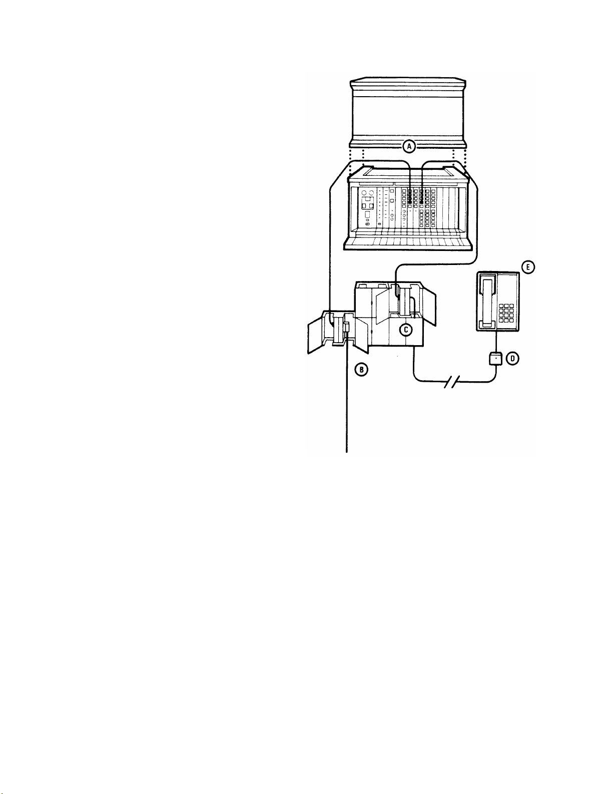
BASIC CONFIGURATION
A.
Control unit: The control unit is
the heart of the MERLIN system.
It provides the power and
intelligence for all voice terminals
as well as the connection
between voice terminals and
outside lines. Program memory
for the MERLIN system resides
in the control unit.
Model 1030 is the basic control
unit (the lower half of the unit
illustrated) and has a capacity of
10 lines and 30 voice terminals or
telephones. Model 3070, with the
expansion unit mounted above
the basic control unit as
illustrated, has a capacity of 30
lines and 70 voice terminals or
telephones.
B.
Network interface: The network
interface connects the control unit
and the outside lines. The most
common network interface is the
25-pair amphenol connector
(RJ21) illustrated. However, the
network interface may be
different (see the Installation
Guide: Models 1030 and 3070).
C.
Jack field: The jack field connects the control unit and modular jacks for the voice
terminals. Optional attachments (extra alerts, paging systems, etc.) may also connect to
the control unit through the jack field.
D.
Modular jack: Each voice terminal wiring run from the jack field terminates in a modular
jack. Every voice terminal has a separate modular jack.
E.
Voice terminal: The voice terminal provides not only basic telephone functions, but also
access, usually by programmable buttons, to the advanced feature software residing in
the control unit. Basic Touch-Tone and rotary-dial telephones may also be used with the
MERLIN system. These telephones access system features by means of dial codes.
4
Page 7
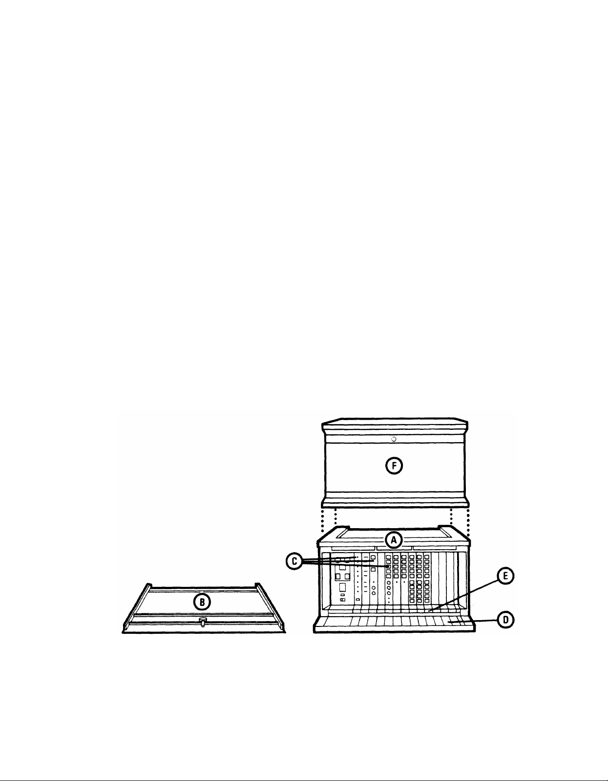
CONTROL UNIT
The control unit provides power for all voice terminals and most accessories. All outside lines
and all voice terminals and telephones connect to the control unit, which contains the
microprocessor and modules for all the advanced features available with the MERLIN system.
Model 1030 consists of a basic control unit (A). Behind the removable front panel (B) of the
control unit, the modules (C) are arranged vertically across the width of the unit. Each vertical
position serves the particular function defined on the colored band on the base (D). Tabs (E)
on the individual modules are color-coded to the appropriate positions. Module positions in
the basic control unit are numbered on the colored band (from left to right) I through I5.
Positions reserved for optional features and services may be vacant and will have protective
plastic covers.
In Model 3070, an expansion unit (F) is mounted on top of the control unit. Additional
modules, located behind the removable front panel of the expansion unit, increase the
capacity of the system to up to 30 lines and 70 voice terminals or telephones. Module
positions in the expansion unit are numbered 16 through 28. Wiring connecting the two units
runs inside the cabinets behind the modules.
Modules are electrically connected to the control unit via pins located at the rear of the module
slots. Abrupt insertion or removal of modules may cause pins to bend, triggering problems
within the control unit. (For any problem common to several voice terminals, it is advisable to
examine the pins.)
5
Page 8
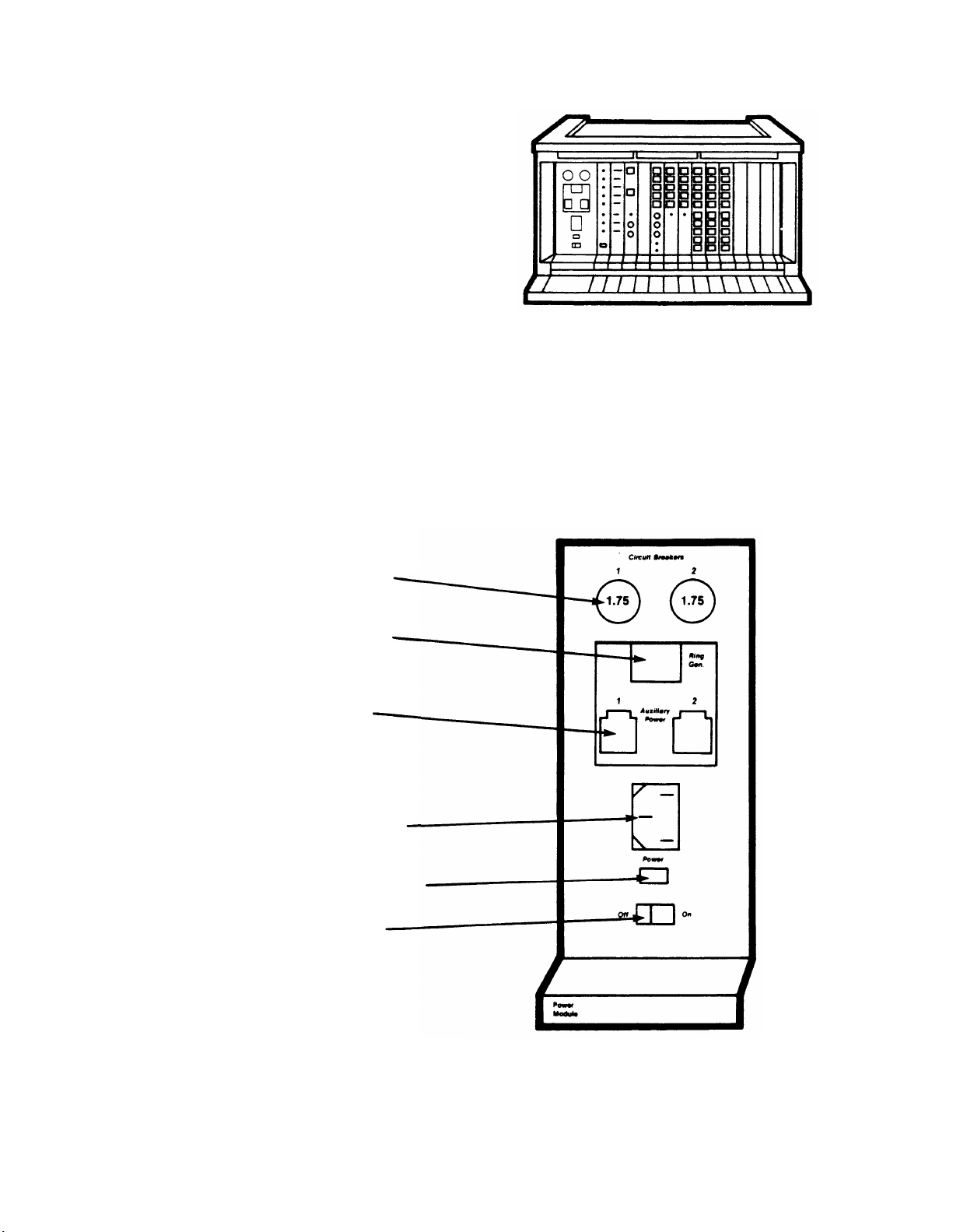
POWER MODULE
The Power Module, color-coded red, occupies position 1 and supplies power to the entire
Model 1030 control unit. In Model 3070, a second Power Module in position 16 of the
expansion unit supplies power for lines CO through C4 and D0 through D4 and intercoms 40
through 69. (The Line Module description on page 12 explains how line designations are
determined; the Voice Terminal Module description on page 13 explains how intercom
designations are determined.) In systems with more than 20 lines or more than 60 voice
terminals or telephones, a Supplementary Power Module occupies position 27 in the
expansion unit and supplies power to lines E0 through E4, lines F0 through F4, and intercoms
70 through 79.
Circuit Breakers: Provide
current surge protection for the
control unit.
Ring Gen. jack: Provides
connection for Ring Generator
Unit needed for basic
telephones.
Auxiliary Power jacks:
Provide connections for
Auxiliary Power Units needed
for systems with many
accessories or 34-button
deluxe voice terminals.
Power receptacle: Provides
connection for ac power cord
plug.
Power light (green): Goes on
when power is on.
On/Off switch: Turns ac
power on and off; resets
control unit when switches on
Processor Module are
changed.
6
Page 9
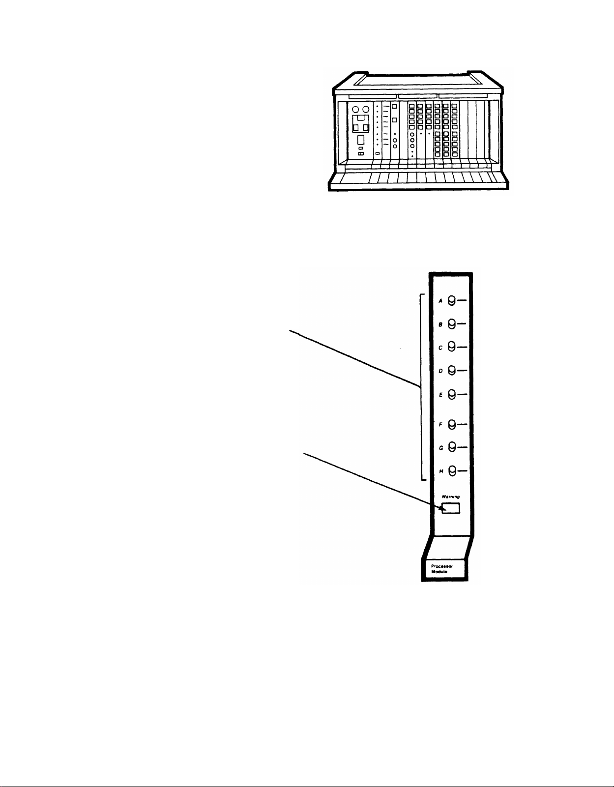
PROCESSOR MODULE
The Processor Module, color-coded violet, occupies position 2. This module contains the
microprocessor which runs all the programs stored in the Feature Module (see page 8) of the
MERLIN
system.
Switches A through H: Each switch on
the Processor Module aligns with a label
on the Feature Module in position 3 when
both modules are in place. The function of
each switch is indicated by the
corresponding label on the Feature
Module. (Refer to the Administration
Manual: Models 1030 and 3070 associated
with the Feature Module for specific
information about the switches.)
Warning light (red): When power is
turned on, the warning light goes on briefly
(while the module runs certain internal
diagnostics) and then goes out. It remains
on if there is a problem with the control
unit, for example, if a module is not
completely plugged in. It goes on again if
a problem occurs while the system is
running.
7
Page 10
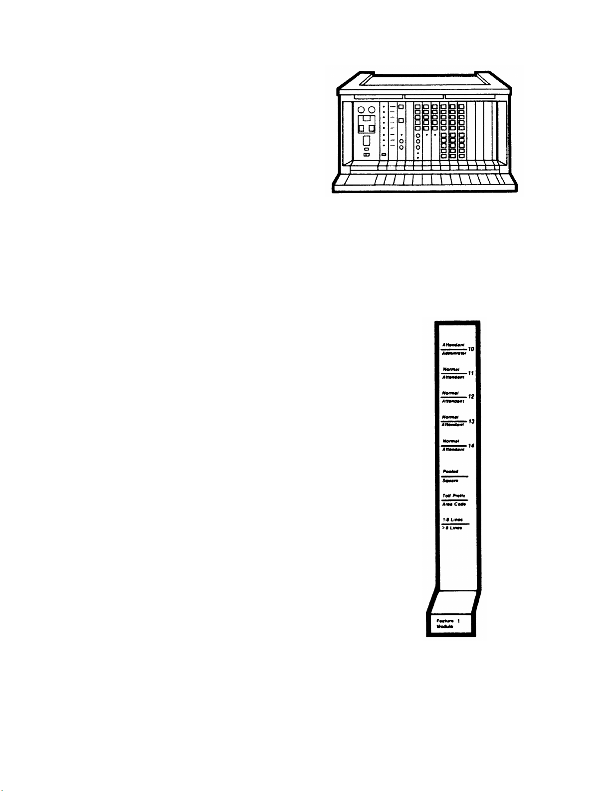
FEATURE MODULE
Feature Module 1, color-coded orange, occupies position 3. Feature Module 1 is the first in a
series. This module contains all programs for the MERLIN system features on ROM (readonly memory) chips. The individual voice terminal has no memory or programming capabilities
in itself. A voice terminal, when connected to the MERLIN system, can be programmed to
perform specific functions (for example, automatic dialing of home number). However, the
actual program instructions are stored in the Feature Module, not in the voice terminal. The
system will not operate without a Feature Module in position 3.
Labels on the Feature Module indicate the
functions of the corresponding switches on
the Processor Module in position 2.
Numbers on the top five positions are
intercom designations (see Voice Terminal
Module description, page 13, for
discussion on how intercom designations
are determined).
Refer to the Administration Manual:
Models 1030 and 3070 for specific
information about the switch definitions on
Feature Module 1.
8
Page 11
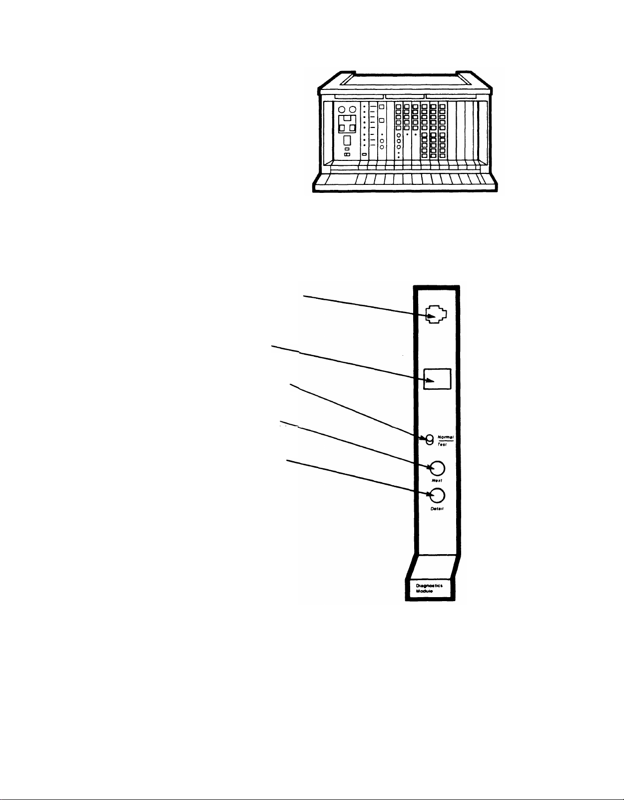
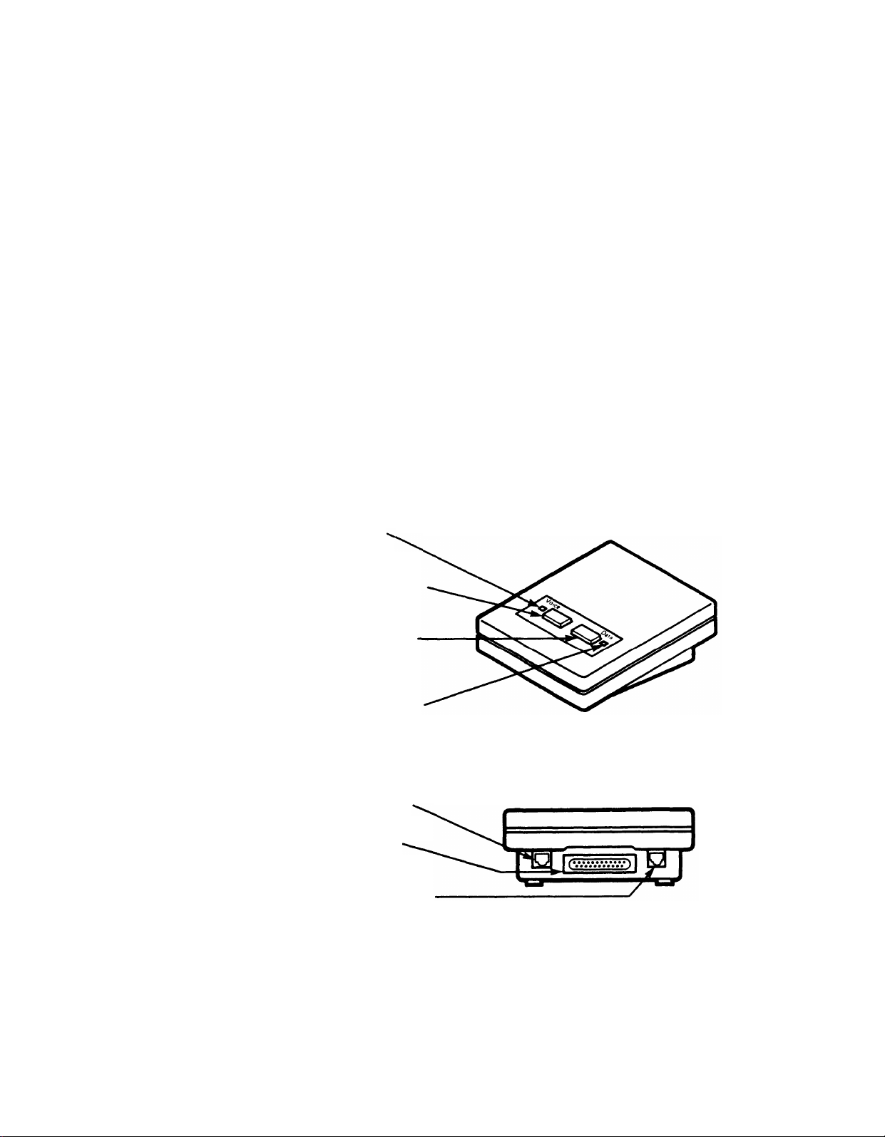
DIAGNOSTICS MODULE (OPTIONAL)
The Diagnostics Module, an optional module color-coded orange, occupies position 4. (When
the Diagnostics Module is not used, a plastic cover protects position 4.) The Diagnostics
Module permits testing of memory and individual Line, Voice Terminal, and Basic Telephone
Modules.
EIA RS-232c jack: Permits connection of a
data terminal for more detailed testing.
This jack is covered with a plastic tab if a
data terminal is not used.
4-character alphanumeric display:
Provides diagnostic messages during
testing.
Normal/Test switch: Permits normal call
processing when set to Normal; permits
diagnostic testing when set to Test.
Next pushbutton: Pressed to resume
testing when diagnostics are interrupted by
a problem.
Detail pushbutton: Pressed to request
further information when *
character display area, signaling detection
of a problem.
See CIB 3018: Diagnostics Module under
the Diagnostics tab divider for further
information about the Diagnostics Module.
appears in the
MODULE A
Position 5, color-coded gold, is reserved for future use. At present a plastic cover
protects this position.
9
Page 12
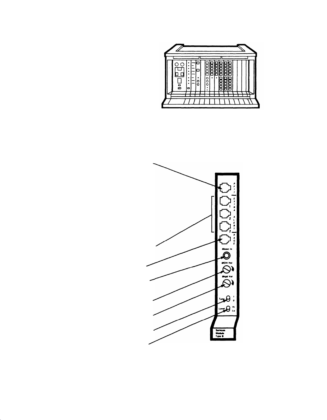
SERVICES MODULE TYPE B (OPTIONAL)
The Services Module (Type B), an optional module color-coded yellow, occupies position 6.
When a Type B module is not used, a plastic cover protects position 6. The Services Module
provides connections for auxiliary equipment: single- and multizone paging systems, music
sources, extra alerts, and Power Failure Transfer Telephones.
PFTT jack: Provides connection for up to
four backup basic Touch-Tone or rotary
telephones (Power Failure Transfer
Telephones). Service will automatically
switch over to these telephones if power to
the control unit is interrupted. When
power is restored, service will automatically
switch back to the control unit. A single
telephone plugged into the module
connects with line A0. When connected
through a 4-Way Modjack Adapter, four
phones will access lines A0, A1, B0, and
B1. (See Line Module description, page
12, for information on line designations.)
Extra Alert jacks: Provide connections for
three separately controllable extra alerts
(horns, bells, chimes, strobes, etc.).
Page jack: Provides connections for a
single- or multizone paging system.
Music In jack: Provides a music source
connection for Music-on-Hold and
Background Music features.
MOH Vol screw: Controls the volume for
Music-on-Hold.
Bkgd Vol screw: Controls the volume for
Background Music.
Tone switch: Turns paging signal on and
off (1 = on, 0 = off).
Level switch: Sets impedance level for
music source.
10
CIB 3016
Page 13
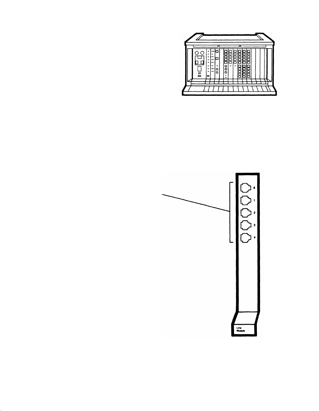
LINE MODULE
The Line Module, color-coded green, occupies position 7. Additional Line Modules (up to five)
can occupy position 8 in the control unit and positions 17, 18, 19, and 20 in the expansion
unit. Line Module positions are labeled on the colored bands on the control unit and the
expansion unit with the letters A through F in addition to position numbers 7, 8, 17, 18, 19,
and 20. Each Line Module provides connections for five outside lines via modular jacks
labeled 0 through 4. Both the module and the jack to which a line connects determine the line
designation: The designation is the letter label of the module position plus the number of the
jack on that module to which the line connects. For example, the line plugged into the third
jack on the module in position 8 (labeled Lines B0 to B4) is designated B2.
Jacks numbered 0 through 4 provide
connection to outside lines.
CIB 3014
11
Page 14
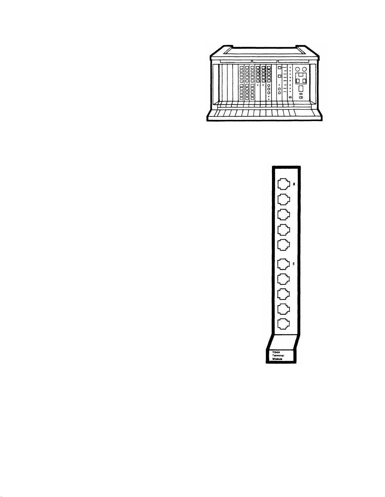
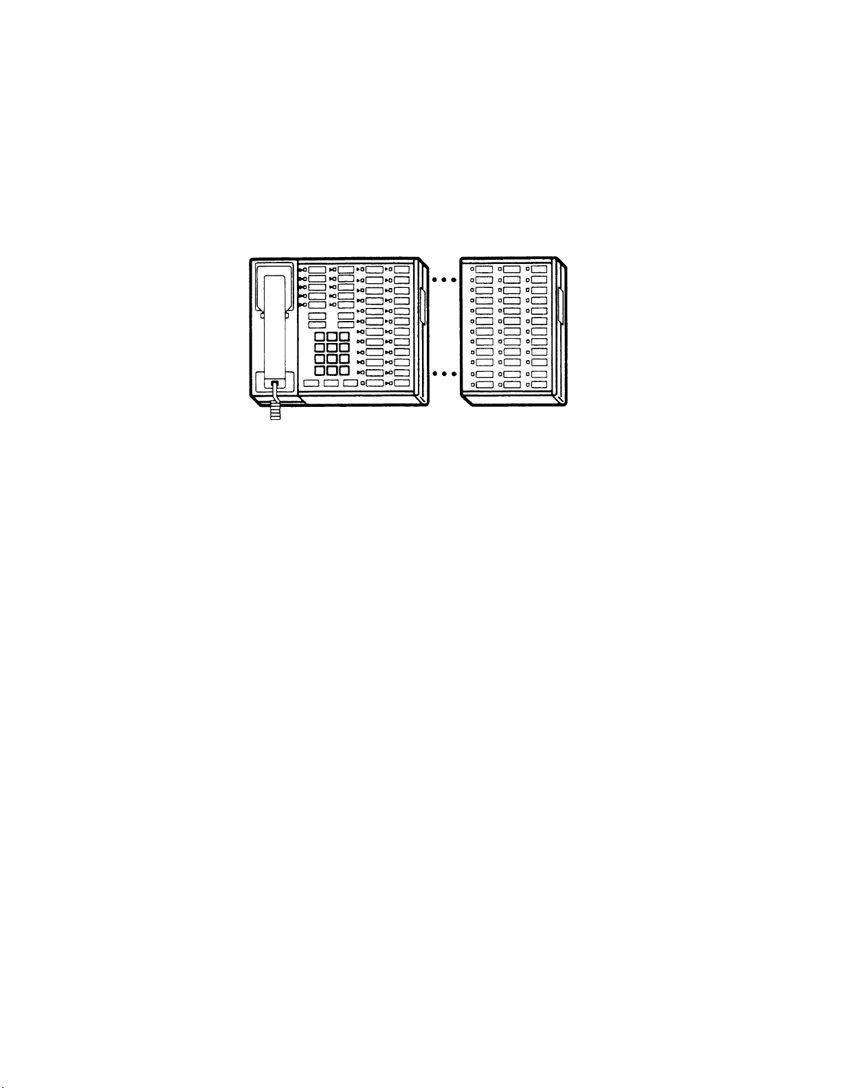
VOICE TERMINAL MODULE
The Voice Terminal Module, color-coded blue, occupies position 9 (labeled Intercoms 10 to
19). Up to six additional Voice Terminal Modules can occupy positions 10 and 11 in the
Model 1030 control unit, and positions 21, 22, 23, and 24 in the expansion unit. The seven
Voice Terminal Module positions are labeled on the colored bands
on the control unit and the expansion unit with intercom
designations (Intercom 10 to 19, Intercom 20 to 29, etc., through
Intercom 70 to 79) in addition to position numbers 9, 10, 11, 21,
22, 23, and 24. Each Voice Terminal Module provides connections
for 10 voice terminals via 4-pair modular jacks (only jacks 0 and 5
are numbered). Both the module position and the jack number
determine the intercom number for each voice terminal. For
example, the voice terminal connected to the third jack from the
top in position 11 (labeled Intercoms 30 to 39) is number 32.
CIB 3013
BASIC TELEPHONE MODULE (OPTIONAL)
Basic Telephone Modules are interchangeable with Voice Terminal Modules and occupy the
same positions (except for position 9). These modules allow for connection of basic TouchTone and rotary telephones to the MERLIN system via modular jacks. Advanced features are
available through dial-access codes (see User’s Guide for Basic Touch-Tone and Rotary
Telephones). A Ring Generator Unit must be connected to the Power Module to provide
ringing current to the telephones connected to the Basic Telephone Module.
CIB 3040
12
Page 15
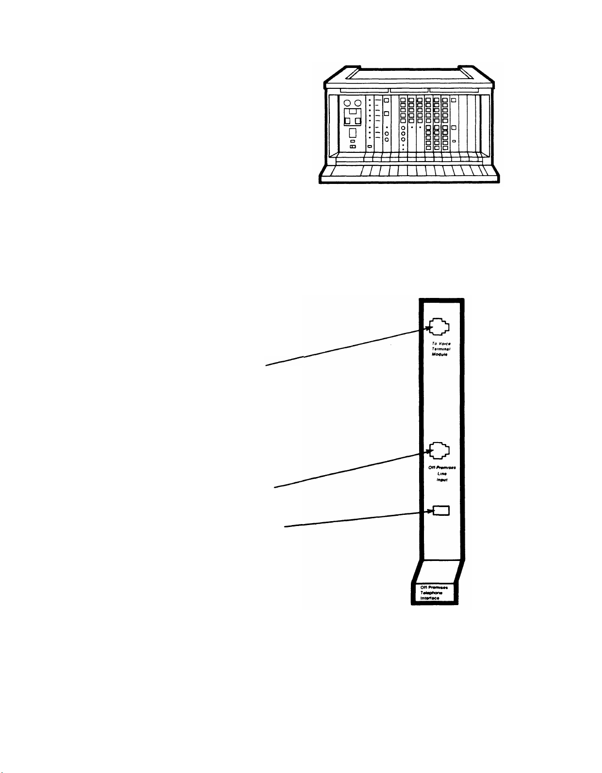
OFF-PREMISES TELEPHONE INTERFACE TYPE C (OPTIONAL)
The Off-Premises Telephone Interface, an optional module color-coded gray, may occupy
position 12, 13, or 14 on the Model 1030 control unit or position 25 or 26 on the expansion
unit. This module connects off-premises telephones to the MERLIN communications system,
making the advanced features available to the off-premises user. Unlike the other modules,
this module has no electrical connections to the backplane of the control unit; power is
supplied directly through the top jack connection.
To Voice Terminal Module jack:
Connection via a 4-pair cord is made from
this jack to an open jack on a Voice
Terminal Module. The jack to which this
module is connected determines the
intercom number of the off-premises
telephone. Connecting a 4-pair cord from
this jack to jack 8 on the Voice Terminal
Module in position 9, for example, will
mean the off-premises phone will be
intercom 17.
Off-Premises Line Input jack: Offpremises outside line connects via 2-pair
wire directly to this input.
Power light (green): Goes on when
power is on.
CIB 3009
13
Page 16
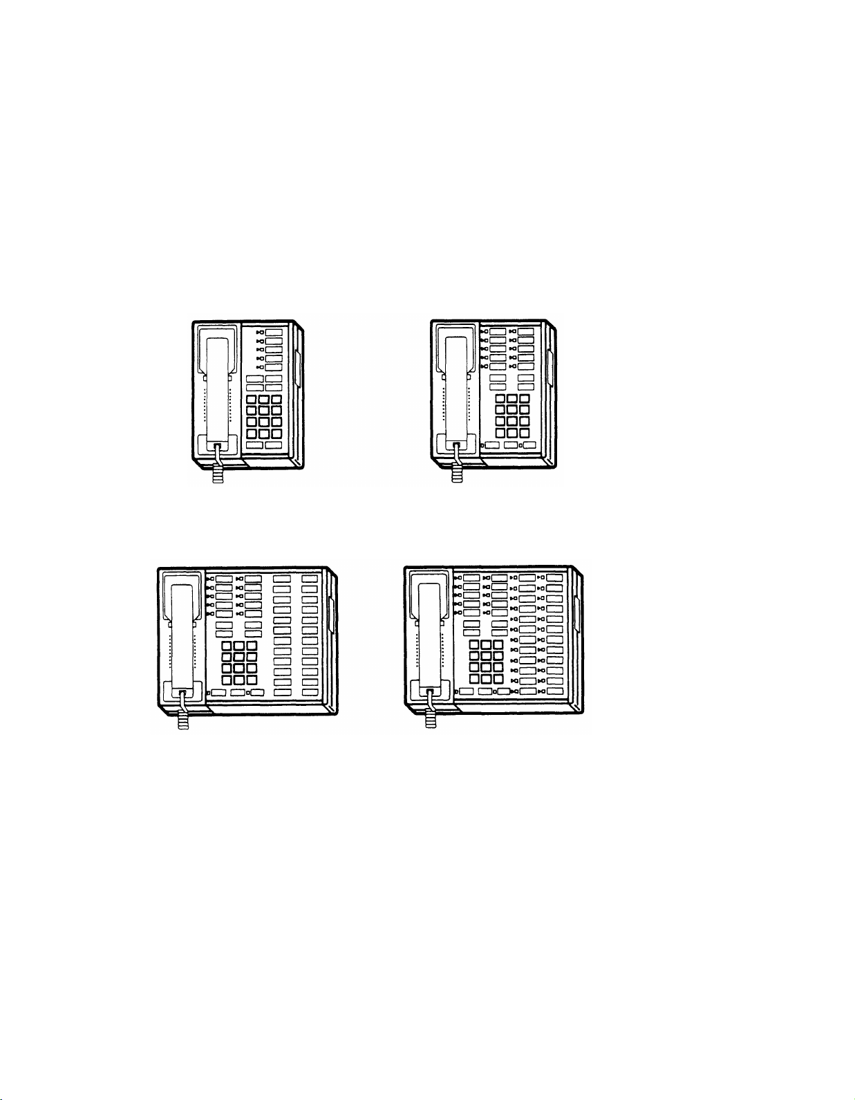
VOICE TERMINALS
Several types of voice terminals may be connected to Model 1030/3070. The different types of
voice terminals are distinguished from each other by the number of silver membrane buttons
above and to the right of the dial pad. These buttons give access to lines and features; most
buttons are programmable. The operation of each voice terminal can be customized by
programming different features to these buttons. (The individual voice terminal has no
memory or programming capabilities by itself, however.
stored in the Feature Module of the control unit.) Refer to the Administration Manual:
Models 1030 and 3070 or the User’s Guide: Models 1030 and 3070 for more information about
voice terminal operation.
Examples of available voice terminals are illustrated below.
Actual program instructions are
5-Button Voice Terminal
34-Button Voice Terminal
10-Button Voice Terminal
34-Button Deluxe Voice Terminal
BASIC TOUCH-TONE/ROTARY TELEPHONE
MERLIN system features are also available using dial-access codes and a Touch-Tone or
rotary telephone (see User’s Guide for Basic Touch-Tone and Rotary Telephones). Basic
telephones are also used for off-premises and power failure backup service. Basic telephones
may connect to the control unit through the Basic Telephone Module, the Off-Premises
Telephone Interface, and the PFTT jack on the Services Module.
14
Page 17

OPTIONAL EQUIPMENT
In addition to the essential components of the MERLIN communications system, several
different accessories may be connected to voice terminals or the control unit.
Optional Voice Terminal Accessories
Hands-Free Units, Headset Adapters, and Multipurpose Adapters can be connected directly to
the underside of the voice terminal, illustrated below. A Voice Terminal Power Supply can
also be connected to a voice terminal and an ac outlet.
Line jack: Connects to control unit
via modular voice terminal cord.
This jack is not to be used for
voice terminal accessories.
“Other” jack: Connects to
optional voice terminal accessories
via voice terminal accessory cord.
This jack is usually covered by an
adhesive-backed paper label.
Hands-Free Unit (HFU)
The Hands-Free Unit provides speakerphone capability, making it possible to place and
receive outside and intercom calls without using the voice terminal handset. The HFU, shown
below, can be used with 10-button or 34-button voice terminals.
Voice terminal accessory cord:
Connects to “Other” jack on voice
terminal.
Speakerphone light: Lights when
speakerphone is in use.
Speakerphone switch: Turns unit
on and off.
Microphone light: Goes on when
microphone is in use.
Volume control
Microphone switch: Turns
microphone on and off for “mute”
function.
CIB 2864
15
Page 18
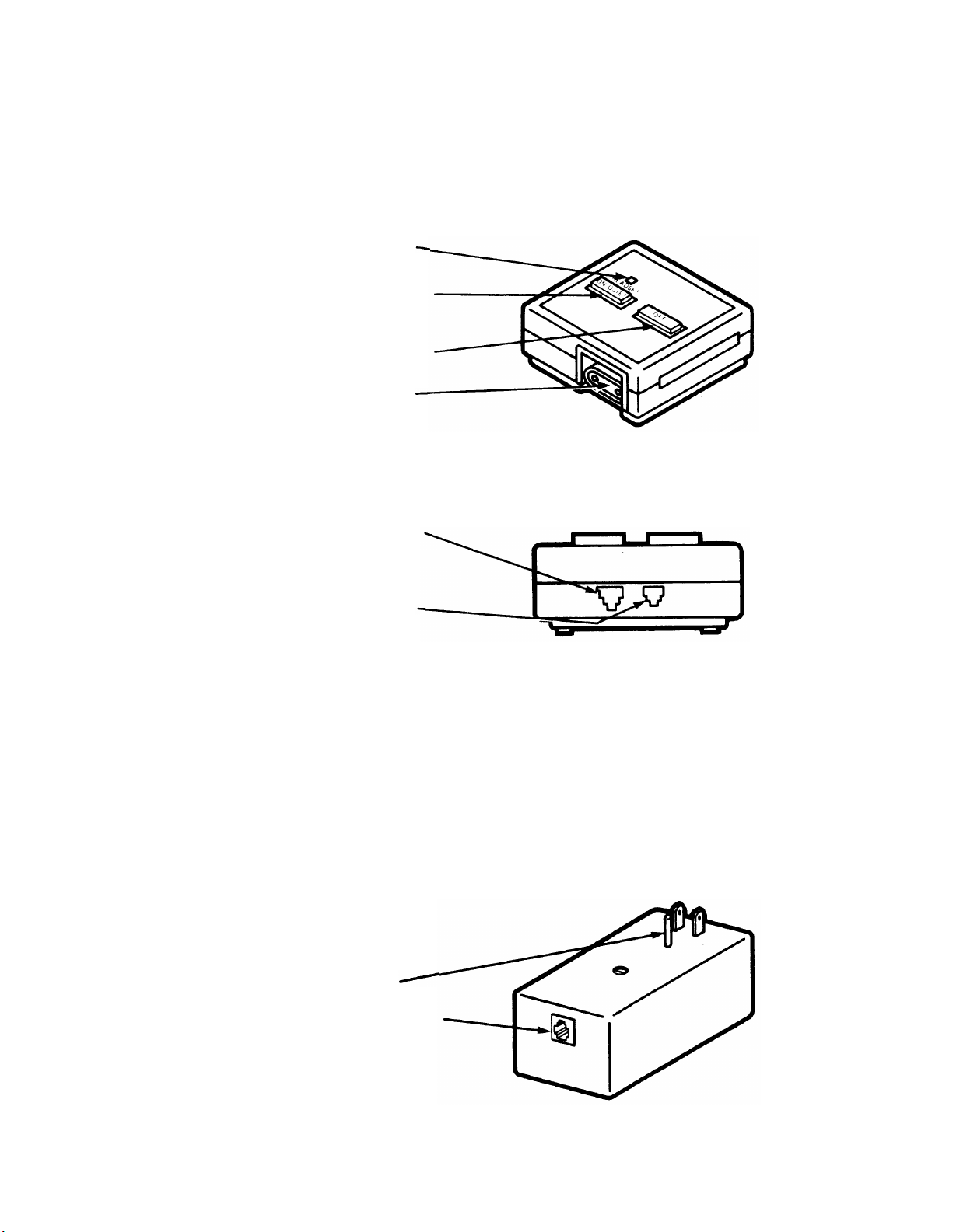
Headset Adapter
The Headset Adapter makes it possible to use a headset with a 10-button or 34-button voice
terminal.
Headset light: Goes on when
headset is in use.
On/Quiet switch: Turns adapter
sound on; when held down,
provides “mute” function.
Off switch: Turns adapter sound
off.
Jack: Provides connection for
headset equipped with 2-prong
plug.
Front
Jack: Provides connection by a
voice terminal accessory cord to
the “Other” jack on the voice
terminal.
Jack: Provides connection for
headset equipped with modular
plug.
Back
CIB 2867
Voice Terminal Power Supply
A Voice Terminal Power Supply provides extra power to 34-button deluxe voice terminals and
attendant consoles. The power supply plugs into an ac outlet not controlled by a switch. A
cord (included with the power supply) connects it to one jack of a 2-jack adapter (also
included). The modular terminal cord from the voice terminal plugs into the other jack on the
adapter. The adapter has a plug end that connects to a modular jack mounted near the voice
terminal.
Plug: Connects to ac outlet.
Output jack: Provides connection
for cord to Z400F Adapter.
16
CIB 3007
Page 19
Multipurpose Adapters
The Manual Multipurpose Adapter (illustrated below)
permits these devices to be connected to
a voice terminal:
Modems and data terminals with builtin modems.
●
an AT&T 212A-type modem with a special cable.
(An extra telephone is not needed with
Automatic answering modems cannot be
used.)
Basic Touch-Tone or rotary telephones. (These telephones will not ring for incoming calls.
●
Calls cannot be dialed out on rotary telephones.)
●
Speakerphones and conference phones.
Touch-Tone automatic dialers.
●
Cordless telephones. (Cordless telephones will not ring for incoming calls. Calls cannot
●
be dialed out on cordless rotary telephones.)
Facsimile machines.
●
The Automatic Multipurpose Adapter, very similar in appearance to the Manual Multipurpose
Adapter, can be differentiated by the word AUTO on the front surface. It permits the same
attachments as the manual adapter and also allows for connection of an answering machine
or automatic answering modem to a voice terminal.
Voice light: Goes on when
modular connector on back is
active.
Voice switch: Pressed to access
devices attached through the
modular jack on the back.
Data switch: Pressed to access
the 212A-type modem connector
on the back; deactivates the
modular jack on the back.
Data light: Goes on when 212Atype modem connector is active.
Front
2-pair modular jack: Connects
the devices listed above.
25-pair connector: Connects
212A-type modems.
Jack: Connects cord to the
“Other” jack on the voice terminal.
Back
CIB 3008
17
Page 20
Attendant Intercom Selector
The Attendant Intercom Selector can be attached to a 34-button deluxe voice terminal. The
selector’s 30 buttons can be used to access up to 70 Intercom Auto Dial numbers. The light
beside each button indicates whether a voice terminal or basic telephone is busy and whether
its message light is on (voice terminals only).
CIB 3026
Optional Control Unit Accessories
Some optional accessories connect directly to the control unit to give the MERLIN system
additional capabilities.
Ring Generator Unit
The Ring Generator Unit must be connected to the Power Module on the control unit to
provide ringing current when basic Touch-Tone or rotary telephones are connected to a Basic
Telephone Module. The Ring Generator Unit looks similar to the Auxiliary Power Unit
illustrated on page 19. However, the Ring Generator Unit has, in place of the Aux Power jack,
a permanent cord with a plug that connects to the Ring Gen. jack on the Power Module.
CIB 3019
18
Page 21
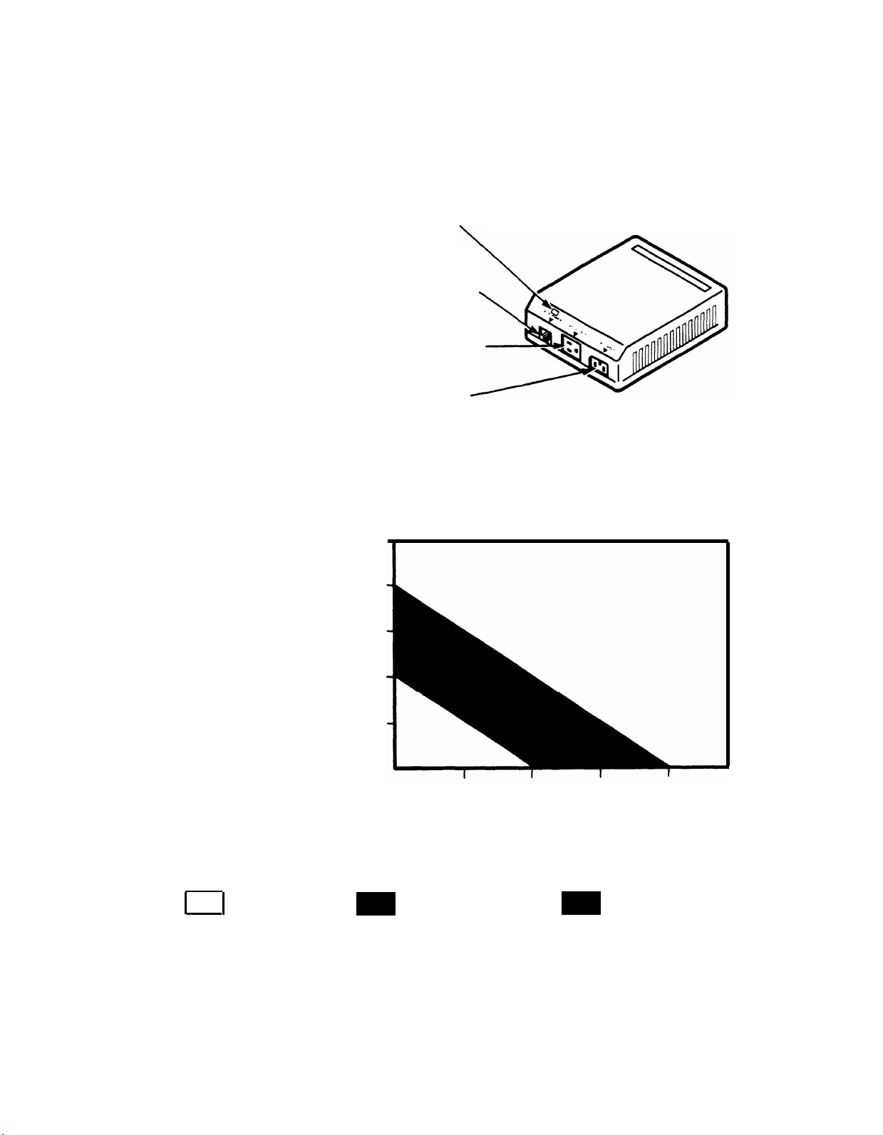
Auxiliary Power Unit
The Auxiliary Power Unit connects to the
unit in systems with many accessories or
Power Module to provide extra power to the control
34-button deluxe voice terminals.
Aux Power light: Goes on when the
Auxiliary Power Unit is connected to
the Power Module of the control unit.
Aux Power jack: Connects via dc cord
(supplied) to the Auxiliary Power jack on
the Power Module of the control unit.
AC Output jack: Connects the ac power
cord from the control unit.
AC Input connector: Connects power
cord to an ac outlet.
The graph below indicates when an Auxiliary Power Unit is necessary.
100
Total number of
5-, 10-, & 34-button
voice terminals,
and Hands-Free Units
Control unit power
supply is sufficient
80
60
40
20
10
One Auxiliary Power Unit
is necessary
20
Total number of 34-button
deluxe voice terminals
30
Two Auxiliary Power Units
are necessary
40
50
19
Page 22
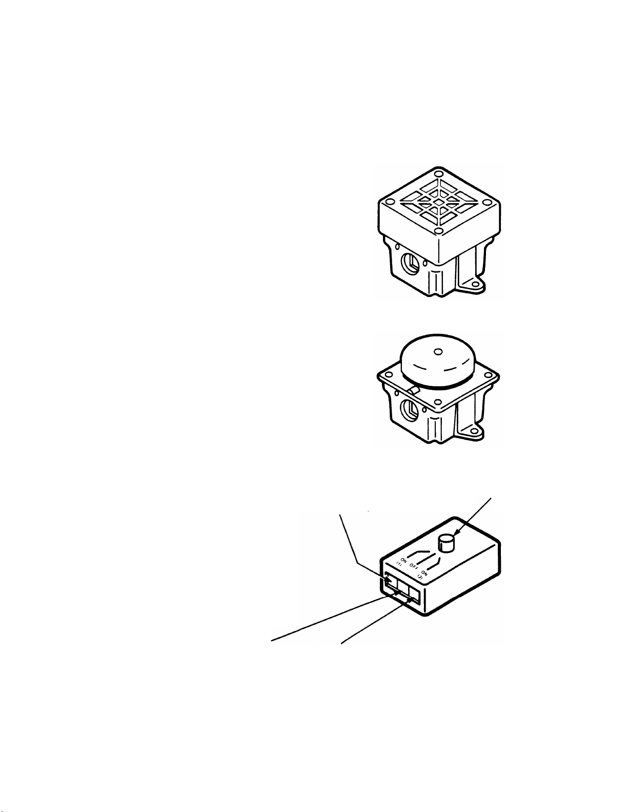
Extra Alerts
Extra alerts such as horns and bells provide signaling in large, open areas (for example,
warehouses and parking lots) and especially noisy environments. Extra alerts connect either
directly to the Services Module on the control unit or by the Extra Alert Switch.
Extra Alert Horn: Provides a loud
signal in noisy environments where
a unique, non-bell sound must be
heard over a large area. It can be
used indoors or out.
Extra Alert Bell: Alerts people
that a telephone is ringing by
providing a loud signal in remote or
noisy areas. It can be used
indoors or out.
20
Extra Alert Switch: Connects two
extra alerts. Turns alert signals on
and off (if an alerting device is
connected to only one jack) and
selects between alternate signals,
for example an alert strobe during
business hours and an alert horn
at night (if alerting devices are
connected to both device jacks). A
Line Bridging Adapter inserted into
either device jack permits
connection of a second alerting
device to that device jack.
Jack: Connects to Services
Module of control unit.
Select switch
Device 1 jack
Device 2 jack
Page 23

Isolating and Correcting Troubles
To isolate and correct a trouble:
FIRST: Determine if more than one voice terminal or basic Touch-Tone or rotary
telephone is experiencing the trouble.
SECOND: If the trouble appears on only one voice terminal or telephone, find the
symptom in the list below titled “A. Trouble on One Telephone.” The list includes
examples of problems categorized under each symptom. Turn to the tab divider for the
symptom and follow the procedures for your specific problem.
If the same problem appears on all or most telephones, find the
“B. Trouble on Several Telephones.” Turn to the tab divider for
the procedures for your specific problem.
For any problem common to several voice terminals or telephones, check for bent or
broken pins on the control unit backplane.
equipment supplier. Never reinsert a module in a slot with bent pins.
Refer to the functional overview or CIBs in this manual if you need more detail on any
component. For more information on programming voice terminals, refer to the User’s Guide:
Models 1030 and 3070 and Administration Manual: Models 1030 and 3070 that come with the
Feature Module.
The index will also help you find information on specific problems. If you cannot find your
problem in the symptom list or index, contact your equipment supplier.
TROUBLE ON ONE TELEPHONE
A.
If any pins are damaged, contact your
symptom in the list titled
the symptom and follow
Symptoms
1.
Ringing (no ringing, constant ringing, etc.)
Dialing (no dial tone, trouble with Auto Dial buttons, etc.)
2.
Hearing (user or outside caller cannot hear, etc.)
3.
Lights (voice terminal has no lights or lights behave in peculiar ways)
4.
Features (problems with holding calls, transferring calls, etc.)
5.
Accessories (problems with Hands-Free Units)
6.
Miscellaneous (voice terminal or accessory suddenly fails, etc.).
7.
B.
TROUBLE ON SEVERAL TELEPHONES
Symptoms
Ringing (no ringing on a particular outside line, peculiar ringing, etc.)
1.
2.
Dialing (cannot dial out on one or more outside lines, no dial tone, etc.)
Hearing (cannot hear outside party clearly, etc.)
3.
Lights (dim lights, etc.)
4.
5.
Features (problems with transferring calls, holding calls, programming buttons, etc.)
21
Page 24

6.
Accessories (problems with music, paging, etc.)
Entire System Down (no lights on control unit and no voice terminals operative)
7.
Miscellaneous (dropped calls, etc.).
8.
NOTE:
Pages within the individual trouble sections are numbered in an unusual way to make
this manual easy to update.
section—
within that section—Ringing. The 4 indicates the fourth page of ringing symptoms.
Refer to the letters and numbers on the tab dividers for help in finding page numbers
listed in the index.
“A. Trouble on One Telephone.”
In page number A1-4, for instance, the A indicates the
The 1 indicates the first trouble category
22
Page 25

TROUBLE ON ONE TELEPHONE
Ringing Symptoms
A line rings but no caller is on the line
10-button voice terminals exhibit peculiar ringing and/or extra lights are lit
Voice terminal rings constantly, whether on or off hook
Voice terminal does not ring when a call is transferred to it
Voice terminal does not ring on incoming outside calls
Voice terminal rings but none of the lights beside the line buttons are lit
Off-premises telephone rings after user hangs up
A particular outside line does not ring
NOTE:
Use this section only if you have isolated the problem to one voice terminal or
telephone (in other words, it is not a systemwide problem).
A1-3
A1-3
A1-4
A1-5
A1-6
A1-8
A1-8
A1-9
A1-1
Page 26

A1-2
Page 27

Symptom:
TROUBLE ON ONE TELEPHONE
Ringing
A line rings but no caller is on the line. (The user attempts to answer a call but
loses it and receives dial tone on a different line.)
Possible Cause
User rocked the handset while lifting
it.
Recommended Action
Rocking the handset causes the voice terminal to
go off hook, on hook, then off hook again. Instruct
the user to lift the handset without rocking it to
either side.
Symptom: 10-button voice terminals exhibit peculiar ringing and/or extra lights are lit.
Possible Cause
A brief ac power outage occurred.
Recommended Action
A brief ac power outage causes certain early
production 10-button voice terminals to exhibit
peculiar ringing. Extra lights also may be on.
Momentarily removing ac power from the voice
terminal will correct the problem. Do this by
unplugging the voice terminal cord at the modular
jack and plugging it in again.
A1-3
Page 28
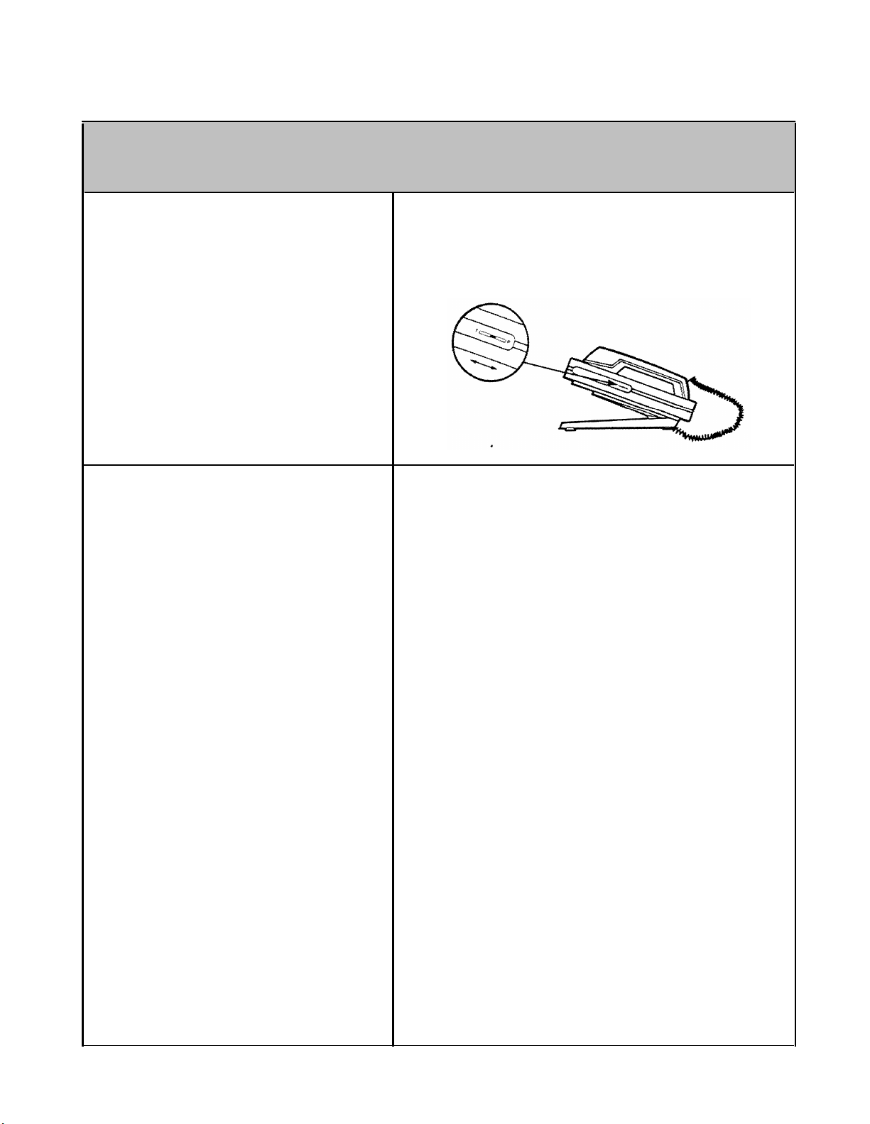
TROUBLE ON ONE TELEPHONE
Ringing
Symptom:
Voice terminal rings constantly, whether on or off hook.
Possible Cause
Voice terminal T/P switch is not
1.
in center position.
2.
Voice terminal is defective.
Recommended Action
1. Make sure the T/P switch is in the center
position.
2. When the ringing occurs only on incoming
calls and continues even when the user picks
up the handset, the switchhook may be
sticking. If it is, replace the voice terminal.
A1-4
Page 29
TROUBLE ON ONE TELEPHONE
Ringing
Symptom:
Voice terminal does not ring when a call is transferred to it.
Possible Cause
The call is being transferred to
1.
a line not available to the user
or not shown on the user’s line
buttons.
Do Not Disturb feature is
2.
activated.
Recommended Action
1.
If the user does not have the line or line
button, the person answering the call should
transfer it by touching Conference instead of
Transfer. See the User’s Guide: Models
1030 and 3070 for steps to establish an
outside/intercom conference.
If the green light is on next to a Do Not
2.
Disturb button, touch the button to deactivate
the feature.
Do Not Disturb may be programmed on a
button without lights beside it, a mislabeled
button, or an unlabeled button. Follow these
steps to see if the feature is programmed and
activated:
Enter program mode by sliding the T/P
a.
switch to the P position.
Touch Intercom Ring.
b.
Dial *71 from the dial pad.
c.
d.
Look at the lights beside Intercom Ring.
Their status (on or off) means the
following:
RED
GREEN
Feature is not programmed
Off
On
On
To change the Status of Do Not Disturb,
e.
Off
Off
or activated.
Feature is programmed but
not activated.
Feature is programmed and
activated.
On
touch Intercom Ring until the desired
pattern of lights appears.
Or, program Do Not Disturb on a button
with lights (strongly recommended). This
will remove the feature from its present
position.
Touch the button to deactivate
the feature in its new position. Relabel
buttons accordingly.
f.
Slide the T/P switch to the center
position.
A1-5
Page 30
TROUBLE ON ONE TELEPHONE
Ringing
Symptom:
Voice terminal does not ring on incoming outside calls.
Possible Cause
Volume control setting is too
1.
low.
2.
User programming of line
ringing options is incorrect.
Recommended Action
Slide volume control to a higher position and
1.
test by making a call to one of the user’s
outside lines from another voice terminal.
2.
See if voice terminal is programmed for “no
ring.”
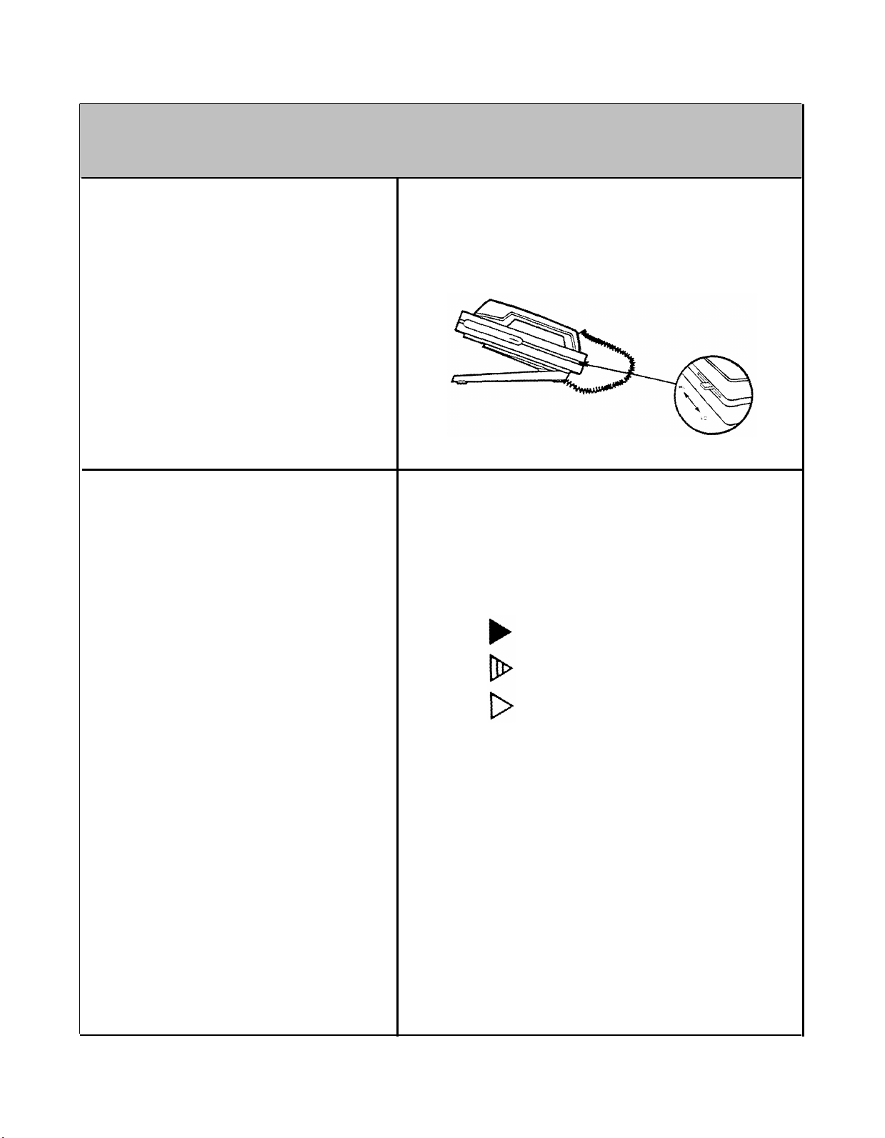
Slide T/P switch to P (program) position.
a.
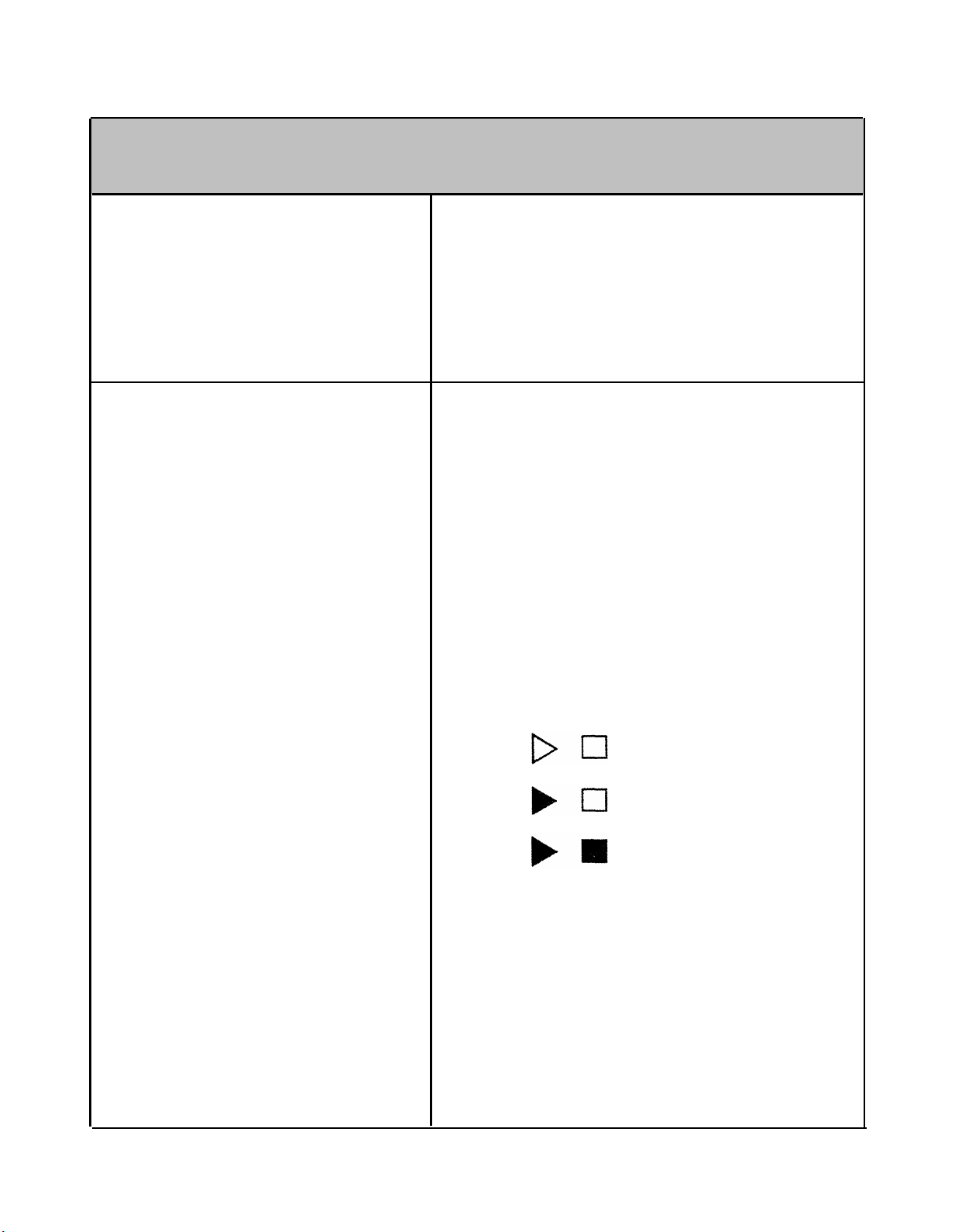
Check red light associated with the line
b.
that doesn’t ring. The red light indicates
how the line is programmed for ringing:
On = ringing
Flashing = delayed ring
Off = no ring
If the red light is off, the line is
programmed for “no ring.” Change it by
touching the line button until the light is
on or flashing.
Slide T/P switch to center position.
c.
A1-6
Page 31

3.4.Do Not Disturb feature is
activated.
TROUBLE ON ONE TELEPHONE
3.
If the green light is on next to a Do Not
Disturb button, touch the button to deactivate
the feature.
Do Not Disturb may be programmed on a
button without lights beside it, a mislabeled
button, or an unlableled button. Follow these
steps to see if the feature is programmed and
activated:
Enter program mode by sliding the T/P
a.
switch to the P position.
b. Touch Intercom Ring.
Dial *71 from the dial pad.
c.
d.
Look at the lights beside Intercom Ring.
Their status (on or off) means the
following:
GREEN
RED
Feature is not programmed
Off
Off
or activated.
Ringing
Voice terminal is defective.
Feature is programmed but
On
On
e.
To change the status of Do Not Disturb,
Off
On
not activated.
Feature is programmed and
activated.
touch Intercom Ring until the desired
pattern of lights appears.
Or, program Do Not Disturb on a button
with lights (strongly recommended). This
will remove the feature from its present
position. Touch the button to deactivate
the feature in its new position. Relabel
buttons accordingly.
f.
Slide the T/P switch to the center
position.
Check the voice terminal as follows:
4.
a.
Switch the suspect voice terminal with a
voice terminal known to be working
properly.
b.
Go to another voice terminal and make a
call to the working voice terminal on an
outside line.
If the working voice terminal rings, the
c.
suspect voice terminal is defective.
Replace it.
A1-7
Page 32

TROUBLE ON ONE TELEPHONE
Ringing
Voice terminal rings but none of the light beside the line buttons are lit. (This
Symptom:
problem will occur only on 10-button voice terminals designated as attendant
consoles.)
Possible Cause
The incoming call is on the ninth or
tenth outside line. These lines do
not have line buttons on 10-button
voice terminals designated as
attendant consoles.
Symptom:
Off-premises telephone rings after user hangs up.
Recommended Action
This occurrence is normal. Instruct the user to
answer the call as usual by lifting the handset. (It is
advisable to use 34-button deluxe voice terminals
as attendant consoles to take full advantage of
message, Intercom Auto Dial, and other features.
Possible Cause
The user may accidentally have put
the call on hold by briefly depressing
the switchhook or rocking the
handset.
A1-8
Recommended Action
Advise the user to depress the switchhook firmly or
replace the handset when disconnecting a call.
Page 33

TROUBLE ON ONE TELEPHONE
Symptom: A particular outside line does not ring. Other lines do ring.
Ringing
Possible Cause
User has programmed the line
ringing option to “no ring.”
Recommended Action
if voice terminal is programmed for “no ring.”
See
Slide T/P switch to P (program) position.
a.
Check red light associated with the line that
b.
doesn’t ring. The red light indicates how the
line is programmed for ringing:
On = ringing
Flashing = delayed ring.
Off = no ring
If the red light is off, the line is programmed
for “no ring.” Change it by touching the line
button until the light is on or flashing.
Slide T/P switch to center position.
c.
A1-9
Page 34

TROUBLE ON ONE TELEPHONE
Dialing Symptoms
User hears dial tone but cannot dial out
When trying to access Centrex, PBX, or custom calling features, dialing #
and a feature code does not work
User with off-premises telephone hears intercom dial tone but cannot place an
intercom or outside call
User with basic telephone hears intercom dial tone but cannot place an
outside call
User cannot program alternative long-distance or other computer-based services
on Outside Auto Dial buttons
User lifts handset and does not hear dial tone
Off-premises telephone has no dial tone and cannot receive calls
On a 10- or 34-button voice terminal all outside lines in the right column
above the dial pad do not have dial tone
NOTE:
Use this section only if you have isolated the problem to one voice terminal or
telephone (in other words, it is not a systemwide problem).
A2-3
A2-4
A2-4
A2-5
A2-5
A2-6
A2-8
A2-10
A2-1
Page 35

A2-2
Page 36

TROUBLE ON ONE TELEPHONE
Dialing
Symptom:
User hears dial tone but cannot dial out.
Possible Cause
Voice terminal is toll call
1.
restricted.
2.
Voice terminal is defective.
Recommended Action
The voice terminal may be intentionally
1.
restricted from dialing outside numbers. Ask
the system administrator if the voice terminal
should be restricted. The Administration
Manual: Models 1030 and 3070 contains
instructions for placing or removing restrictions
on outward calls.
2. If the voice terminal is not restricted:
Switch the suspect voice terminal with a
a.
voice terminal known to be working
properly.
b.
Try to dial out on the working voice
terminal.
If you can dial out, the suspect voice
c.
terminal is defective. Replace it.
A2-3
Page 37

TROUBLE ON ONE TELEPHONE
Dialing
Symptom:
When trying to access Centrex, PBX, or custom calling features, dialing # and a
2-digit feature code does not work.
Possible Cause
Dialing #
reserved for speed dialing numbers.
and a 2-digit code is
Recommended Action
To access a Centrex, PBX, or custom calling
feature dial ## then the feature code.
User with off-premises telephone hears intercom dial tone but cannot place an
Symptom:
intercom or ouside call.
Possible Cause
The MERLIN system is in
administration mode. (Users with
voice terminals or telephones not
connected through the Off-Premises
Telephone Interface hear an
intermittent tone when the system is
in administration mode.)
Recommended Action
Instruct the user to wait and try again.
A2-4
Page 38

TROUBLE ON ONE TELEPHONE
Dialing
Symptom:
User with basic telephone hears intercom dial tone but cannot place an outside
call.
Possible Cause
User is not dialing the access
number (for instance, 9).
Recommended Action
Instruct the user to dial the access number before
the ouside number.
Symptom:
User cannot program alternative long-distance or other computer-based services
on Outside Auto Dial buttons.
Possible Cause
Storage capacity of Outside Auto
Dial feature has been exceeded.
Recommended Action
A maximum of 16 digits or characters can be stored
on an Ouside Auto Dial button. Hold(Pause),
Drop(Stop), Recall, or Transfer (for Touch-Tone
Enable) counts as a digit. Program the alternative
service access and code numbers onto one button.
Program the numbers you want to call using those
alternative services onto other Outside Auto Dial
buttons. To dial out, touch the access number
button and wait for the computer tone to sound over
the voice terminal speaker, then touch the next
button.
If a number sequence requires a time interval as a
“wait for dial tone,” touch Hold (Pause) or Drop
(Stop), or split the number sequence at that point.
A2-5
Page 39

TROUBLE ON ONE TELEPHONE
Dialing
Symptom: User lifts handset and does not hear dial tone.
Possible Cause
Voice terminal is outward call
1.
restricted.
2.
All outside lines are busy.
Green lights next to all line
buttons will be lit. No red lights
will be lit.
3.
Many users with basic TouchTone or rotary telephones are
dialing at once.
Recommended Action
1.
The voice terminal may be intentionally
restricted from making outside calls. If the
system administrator wants the voice terminal
unrestricted, refer to the procedures in the
Administration Manual: Models 1030 and 3070.
2.
Instruct the user to hang up the handset and
wait for a free line or use the Line Request
feature (see the User’s Guide: Models 1030
and 3070). If this happens often, adding more
outside lines may be wise. See the Installation
Guide: Models 1030 and 3070 for more
information.
A user with a basic telephone should wait
3.
10 seconds or until dial tone is heard. The
user does not have to hang up the handset
while waiting for dial tone.
A2-6
The voice terminal may be
4.
programmed for Manual Line
Selection instead of Automatic
Line Selection.
Instruct the user to touch a line button to get
4.
dial tone or reprogram the Automatic Line
Selection feature. See the User’s Guide:
Models 1030 and 3070 for instructions.
Page 40

Wiring between the voice
5.
terminal and control unit is
faulty.
TROUBLE ON ONE TELEPHONE
5.
Make sure wiring between network interface
and control unit is not damaged.
Make sure connectors are plugged in
securely.
Dialing
A2-7
Page 41

TROUBLE ON ONE TELEPHONE
Dialing
Symptom: Off-premises telephone has no dial tone and cannot receive calls.
Possible Cause
Wiring between the off-
1.
premises telephone and control
unit is faulty.
2.
Local telephone company line
is faulty.
Recommended Action
1.
Make sure wiring is not damaged and
connectors are plugged in securely between
these points:
●
Between the off-premises telephone and
network interface
●
Between the network interface for the offpremises line and the Off-Premises Line
Input jack on the Off-Premises Telephone
Interface
●
Between the To Voice Terminal Module
jack on the Off-Premises Telephone
Interface and a jack on a Voice Terminal
Module
2.
Plug a basic telephone into the network
interface or jack field line jack at the control
unit.
If there is no dial tone, have the local
telephone company check the line.
A2-8
Page 42

TROUBLE ON ONE TELEPHONE
Dialing
Off-premises telephone is
3.
defective.
Off-Premises Telephone
4.
Interface is defective.
Control unit is defective.
5.
Unplug the suspect off-premises telephone.
3.
Plug in a telephone known to be working
properly. If the trouble does not appear,
replace the suspect telephone.
If the trouble still exists, replace the Off-
4.
Premises Telephone Interface.
If a new module does not solve the problem,
5.
the control unit probably needs repair.
A2-9
Page 43

TROUBLE ON ONE TELEPHONE
Dialing
Symptom:
On a 10- or 34-button voice terminal, all ouside lines in the right column above
the dial pad do not have dial tone.
Possible Cause
This may have happened during
testing if a 5-button voice terminal
was plugged in in place of a 10button voice terminal.
Recommended Action
Instruct the administrator to readminister the outside
lines to the voice terminal. To avoid this problem in
the future, switch voice terminals with others of the
same type during testing.
A2-10
Page 44

TROUBLE ON ONE TELEPHONE
Hearing Symptoms
Outside caller intermittently has trouble hearing a user
User in a noisy room has trouble hearing outside or intercom calls or
hears excessive breath noises from himself or herself
User with off-premises telephone has trouble hearing
NOTE:
Use this section only if you have isolated the problem to one voice terminal or
telephone (in other words, it is not a systemwide problem).
A3-3
A3-3
A3-4
A3-1
Page 45

A3-2
Page 46

TROUBLE ON ONE TELEPHONE
Hearing
Symptom:
Outside caller intermittently has trouble hearing a user.
Possible Cause
Radio-frequency interference (RFI) is
occurring.
Recommended Action
Certain early production voice terminals may be
susceptible to high RFI levels. Voice terminals
manufactured beginning April 1983 have improved
RFI immunity.
replace early production voice terminals with later
vintage models. Make sure the system is
connected to a third-wire (green wire) ground, not a
conduit ground.
necessary.
If a radio transmitter is in the area,
Have an electrician check if
Symptom:
User in a noisy room has trouble hearing outside or intercom calls or hears
excessive breath noises from himself or herself.
Possible Cause
1.
User is holding the handset too
near his or her mouth.
2.
User may need a Push-toListen Handset.
Recommended Action
1. Instruct the user to hold the handset farther
from his or her mouth.
2.
The user may need a Push-to-Listen Handset
(R8-type). It is designed for environments with
a noise level of 80 or more decibels.
A3-3
Page 47

TROUBLE ON ONE TELEPHONE
Hearing
Symptom: User with off-premises telephone has trouble hearing.
Possible Cause
Off-premises telephone may be
1.
defective.
Off-Premises Telephone
2.
Interface may be defective.
Line from the central office to
3.
the off-premises telephone
should be upgraded.
Recommended Action
Switch the suspect off-premises telephone
1.
with a basic Touch-Tone or rotary telephone
known to be working properly. Place an
outside call. If you can hear clearly, replace
the suspect off-premises telephone.
At the control with location, plug the cord for
2.
the off-premises telephone into a different OffPremises Telephone Interface. Have
someone place an outside call from the offpremises telephone. If the user can hear
clearly, replace the suspect Off-Premises
Telephone Interface.
3. Contact the local telephone company
representative about upgrading the line
between the central office and the offpremises telephone. Too much sound is
being lost on the line. Notify the
representative of these specifications for the
off-premises telephones:
●
Standard jacks: USOC code SAY
Facility interface code: FIC OL 13C
●
A3-4
Page 48

TROUBLE ON ONE TELEPHONE
Light Symptoms
Voice terminal behaves abnormally in the test mode (T setting of T/P switch)
NOTE:
Use this section only if you have isolated the problem to one voice terminal or
telephone (in other words, it is not a systemwide problem).
A4-3
A4-1
Page 49

A4-2
Page 50

Symptom:
TROUBLE ON ONE TELEPHONE
Lights
Voice terminal behaves abnormally in the test mode (T setting of T/P switch).
Normally, when a voice terminal is in the test mode the red and green lights flash
alternately and a tone sounds regularly.
Possible Cause
1. Modular jack for the voice
terminal is miswired.
Wiring between the control unit
2.
and voice terminal is faulty.
Recommended Action
1. Make sure the wires from the cable are
terminated in this order from left to right:
1. White-blue
2. Blue
3. White-orange
4. Orange
5. White-green
6. Green
7. White-brown
8. Brown
2.
Make sure the wiring between the voice
terminal, jack field, and contol unit is not
damaged. Make sure the connections are
secure.
Make sure the control unit is connected to a
third-wire (green wire) ground, not a conduit
ground.
A4-3
Page 51

TROUBLE ON ONE TELEPHONE
Lights
3.
Voice terminal is defective.
Control unit Voice Terminal 4. Make sure all cords are labeled before
4.
Module is defective. unplugging them from the voice terminal
3.
Switch the suspect voice terminal with one
known to be working properly. If the trouble
does not appear on the working voice
terminal, the suspect voice terminal is
defective. Replace it.
A surge of static electricity may have caused
the voice terminal to fail. If there is new
carpet near the voice terminal, spray the area
with an antistatic spray or place a rubber mat
under the voice terminal or user’s chair.
modules.
Unplug the cords from the voice terminal
module, insert a spare voice terminal module,
and plug the cords into it. See if the voice
terminal operates normally in the test mode. If
you don’t have a spare voice module, unplug
the cords from another voice terminal module
and use it as a spare.
5.
Control unit is defective.
5.
The pins at the back of the control unit voice
terminal module slot may be damaged or bent.
If so, the control unit will probably require
repair.
Never reinsert a module in a slot with bent
pins. This could create worse problems,
such as destroying the control unit Power
Module or backplane.
A4-4
Page 52

TROUBLE ON ONE TELEPHONE
Feature Symptoms
Voice terminal speaker squeals when user hangs up handset
User can dial out normally from dial pad but Outside Auto Dial button does
not work
User attempts to retrieve a held call and loses it
A call cannot be conferenced
Toll call restricted voice terminal is unable to make a local call
Administrator cannot restrict outside calls at a voice terminal or basic
telephone
Attendant cannot program Intercom Auto Dial feature
When a call is transferred from a basic telephone, the person receiving the
transferred call lifts the handset on the first ring but no caller is present.
When the person hangs up, the voice terminal rings again
Do Not Disturb feature is activated but voice terminal still rings on
certain calls
User with a basic telephone cannot put a call on hold
Intercom calls to 5- or 10-button voice terminal get a busy signal but the
user is not on another line
A5-3
A5-3
A5-4
A5-4
A5-5
A5-6
A5-7
A5-7
A5-8
A5-8
A5-9
User with a basic telephone drops the first outside call while attempting to
conference in a second outside call
NOTE:
Use this section only if you have isolated the problem to one voice terminal or
telephone (in other words, it is not a systemwide problem).
A5-10
A5-1
Page 53

A5-2
Page 54

TROUBLE ON ONE TELEPHONE
Features
Symptom:
Voice terminal speaker squeals when user hangs up handset.
Possible Cause
The speaker is on and sets up a
feedback path with the handset
microphone when the distance
between the two is small.
Recommended Action
Instruct the user to turn the speaker off before
hanging up the handset. Lowering the volume
control setting will also help.
Symptom:
User can dial out normally from dial pad but Outside Auto Dial button does not
work.
Possible Cause
Recall can only be used as the first
element in a stored number.
Recommended Action
Reprogram the number on the Outside Auto Dial
button.
A5-3
Page 55

TROUBLE ON ONE TELEPHONE
Features
Symptom:
User attempts to retrieve a held call and loses it.
Possible Cause
User rocked the handset while lifting
it.
Recommended Action
Rocking the handset causes the voice terminal to
go off hook, on hook, and then off hook again.
Instruct the user to lift the handset without rocking it
to either side.
Symptom:
A call cannot be conferenced.
Possible Cause
1.
User held the call with Transfer
instead of Hold. Touching
Transfer automatically puts a
call on hold, but is incorrect for
conferencing calls.
2. The conference limit may have
been reached.
Recommended Action
1. Instruct the user not to hold a call with
Transfer when that call will be conferenced.
The call should be held with Hold.
2.
Instruct the user that only two outside and two
intercom lines may be conferenced at once.
A5-4
Page 56

TROUBLE ON ONE TELEPHONE
Symptom: Toll call restricted voice terminal is unable to make a local call.
Features
Possible Cause
1.
Toll Prefix/Area Code switch
(switch G on the control unit
Processor Module) may be in
wrong position.
Recommended Action
Check the setting of the Toll Prefix/Area Code
1.
switch.
Set the switch to Toll Prefix if you must dial 0
or 1 before you dial an area code.
Set the switch to Area Code if you begin with
the area code when you dial a long distance
number.
If you change the position of this switch, reset
the control unit by setting the On/Off switch on
the control unit Power Module to Off then to
On.
2.
Toll call restriction may be
misadministered.
2.
The toll restriction may be misprogrammed.
Refer to the Administration Manual: Models
1030 and 3070 for programming instructions.
A5-5
Page 57

TROUBLE ON ONE TELEPHONE
Features
Symptom: Administrator cannot restrict outside calls at a voice terminal or basic telephone.
Possible Cause
Toll Prefix/Area Code switch
1.
(switch G on the control unit
Processor Module) may be in
wrong position.
Recommended Action
Check the setting of the Toll Prefix/Area Code
1.
switch.
Set the switch to Toll Prefix if you must dial 0
or 1 before you dial an area code.
Set the switch to Area Code if you begin with
the area code when you dial a long distance
number.
If you change the position of this switch, reset
the control unit by setting the On/Off switch on
the control unit Power Module to Off, then to
On.
A5-6
Toll call restriction may be
2.
misadministered.
Telephone may be connected
3.
to a Multipurpose Adapter.
2.
The toll restriction may be misprogrammed.
Refer to the Administration Manual: Models
1030 and 3070 for programming instructions.
3.
See if telephones are connected to a
Multipurpose Adapter. Telephones connected
to this accessory cannot be toll call restricted.
Page 58

Symptom:
TROUBLE ON ONE TELEPHONE
Features
Attendant cannot program Intercom Auto Dial feature. This problem occurs only
when switch H on the Processor Module is set to >8. (An attendant can be
intercom 10 or intercoms 11 to 14 if switches B through E on the Processor
Module are set to Attendant.)
Possible Cause
In the >8 mode, an attendant must
have an Attendant Intercom Selector
to use Intercom Auto Dial.
When a call is transferred from a basic telephone, the person receiving the
Symptom:
transferred call lifts the handset on the first ring but no caller is present. When the
person hangs up, the voice terminal rings again.
Recommended Action
Obtain an Attendant Intercom Selector. See the
Attendant’s Guide: Models 1030 and 3070 for
button defaults on the Attendant Intercom Selector.
Possible Cause
The call was not transferred with
voice announcement.
Recommended Action
Instruct users with basic telephones to transfer calls
with voice announcement. The User’s Guide for
Basic Touch-Tone and Rotary Telephones provides
instructions.
A5-7
Page 59

TROUBLE ON ONE TELEPHONE
Features
Symptom: Do Not Disturb feature is activated but voice terminal still rings on certain calls.
Possible Cause
User may be covering calls for
another voice terminal. Calls to the
voice terminal that is covered will
override the Do Not Disturb feature.
Recommended Action
Instruct user to program cover buttons to “no ring”
when activating the Do Not Disturb feature. Refer
to the User’s Guide: Models 1030 and 3070 for
instructions.
Symptom: User with a basic telephone cannot put a call on hold.
Possible Cause
All intercom lines are busy. Intercom
dial tone is necessary when holding
a call.
A5-8
Recommended Action
Instruct the user to wait until an intercom line is
available or ask the caller to put the call on hold on
his or her system.
Page 60

Symptom:
TROUBLE ON ONE TELEPHONE
Features
Intercom calls to 5- or 10-button voice terminals get a busy signal but the user is
not on another line. Outside calls do not ring on the voice terminal either.
Possible Cause
The Do Not Disturb feature is
activated.
Recommended Action
If the green light is on next to a Do Not Disturb
button, touch the button to deactivate the feature.
Do Not Disturb may be programmed on a button
without lights beside it, a mislabeled button, or an
unlabeled button. Follow these steps to see if the
feature is programmed and activated:
Enter program mode by sliding the T/P switch
a.
to the P position.
Touch Intercom Ring.
b.
Dial *71 from the dial pad.
c.
Look at the lights beside Intercom Ring.
d.
Their status (on or off) means the following:
RED GREEN
Feature is not programmed
Off
On Off
Off
or activated.
Feature is programmed but
not activated.
Feature is programmed and
On
To change the status of Do Not Disturb, touch
e.
On
activated.
Intercom Ring until the desired pattern of
lights appears.
Or, program Do Not Disturb on a button with
lights (strongly recommended). This will
remove the feature from its present position.
Touch the button to deactivate the feature in
its new position. Slide the T/P switch to the
center position. Relabel buttons accordingly.
Slide the T/P switch to the center
f.
position.
A5-9
Page 61

TROUBLE ON ONE TELEPHONE
Features
User with a basic telephone drops the first outside call while attempting to
Symptom:
conferece a second outside call.
Possible Cause
The user has put the first call on
hold before dialing the second call.
Recommended Action
Instruct the user to follow this procedure when
conferencing calls:
a.
Place first call.
b.
Announce call.
Press switchhook down firmly and then
c.
release it. Intercorn dial tone will indicate the
call is on hold.
d.
Announce call.
Press switchhook down firmly, then release it.
e.
Conference is now complete.
A5-10
Page 62

TROUBLE ON ONE TELEPHONE
Accessory Symptoms
Lights behave abnormally on a 34-button voice terminal with Hands-Free Unit
NOTE:
Use this section only if you have isolated the problem to one voice terminal or
telephone (in other words, it is not a systemwide problem).
A6-3
A6-1
Page 63

A6-2
Page 64

TROUBLE ON ONE TELEPHONE
Accessories
Symptom:
Lights behave abnormally on a 34-button deluxe voice terminal with Hands-Free
Unit. This may occur at system installation or after a power failure.
Possible Cause
Too much power load is being
placed on the control unit.
Recommended Action
Add a Voice Terminal Power
the power fails or the control
following:
a.
Unplug the HFU.
b.
Set the Power Module On/Off switch to Off,
then to On.
c.
Plug in the HFU.
Supply, or each time
unit is reset do the
A6-3
Page 65

TROUBLE ON ONE TELEPHONE
Miscellaneous Symptoms
Outside lines added to the system do not appear at the attendant position
Outside lines taken away from the system still appear at the attendant position
A voice terminal or voice terminal accessory suddenly fails
NOTE:
Use this section only if you have isolated the problem to one voice terminal or
telephone (in other words, it is not a systemwide problem).
A7-3
A7-3
A7-4
A7-1
Page 66

A7-2
Page 67

TROUBLE ON ONE TELEPHONE
Symptom: Outside lines added to the system do not appear at the attendant position.
Miscellaneous
Possible Cause
The lines added to the system were
not administered to the system.
Recommended Action
Refer to the Administration Manual: Models 1030
and 3070 for instructions on administering these
lines to the system.
Symptom: Outside lines taken away from the system still appear at the attendant position.
Possible Cause
These lines were not administered
out of the system.
Recommended Action
Refer to the Administration Manual: Models 1030
and 3070 for instructions on administering these
lines out of the system.
A7-3
Page 68

TROUBLE ON ONE TELEPHONE
Miscellaneous
Symptom: A voice terminal or voice terminal accessory suddenly fails.
Possible Cause
A surge of static electricity occurred.
Recommended Action
If new carpeting is causing the static electricity,
spray the area with an antistatic spray.
Make sure the control unit is connected to a thirdwire (green-wire) ground, not a conduit ground.
A7-4
Page 69

TROUBLE ON SEVERAL TELEPHONES
Ringing Symptoms
A particular outside line does not ring. Other lines do ring
B1-3
B1-1
Page 70

B1-2
Page 71

TROUBLE ON SEVERAL TELEPHONES
Symptom: A particular outside line does not ring. Other lines do ring.
Ringing
Possible Cause
Wiring between the network
1.
interface and control unit is
faulty.
Recommended Action
Make sure wiring between network interface
1.
and control unit is not damaged.
Make sure connectors are plugged in
securely.
B1-3
Page 72

TROUBLE ON SEVERAL TELEPHONES
Ringing
Local telephone company line
2.
is faulty.
Verify local telephone company line operation
2.
by plugging in a basic telephone at the
network interface or jack field line jack.
If dial tone is not present, arrange for the local
telephone company to repair the line.
B1-4
Control unit Line Module is
3.
defective.
Control unit is defective.
4.
Make sure all cords are labeled before
3.
unplugging them from the line modules.
Unplug the cords from the Line Module, insert
a spare Line Module, and plug the cords into
it. See if the ouside line will ring. (If you
don’t have a spare Line Module, unplug the
cords from another Line Module and use it as
a spare.)
The pins at the back of the control unit Line
4.
Module slot may be damaged or bent. If so,
the control unit will require repair.
Never reinsert a module in a slot with bent
pins. This could create worse problems,
such as destroying the control unit Power
Module or backplane.
Page 73

TROUBLE ON SEVERAL TELEPHONES
Dialing Symptoms
Dial tone is present on all lines, but users cannot dial out on all lines
Dial tone is not present on a particular line but is heard on other lines
Users of 5- and 10-button sets wish to access the ninth and tenth outside lines
Users with basic Touch-Tone telephones hear each Touch-Tone signal twice while
dialing
B2-3
B2-4
B2-6
B2-6
B2-1
Page 74

B2-2
Page 75

TROUBLE ON SEVERAL TELEPHONES
Symptom: Dial tone is present on all lines, but users cannot dial out on all lines.
Dialing
Possible Cause
The Tone/Pulse option for
1.
outside lines may be
misadministered.
If the red Warning light on the
2.
Processor Module of the control
unit is on:
●
The control unit may need
to be reset.
●
Some cord or cable
connections may be loose.
Recommended Action
Refer to the Administration Manual: Models
1.
1030 and 3070 for readministering the
Tone/Pulse option.
If the red Warning light is on:
2.
a.
Set the Power Module On/Off switch to
Off. Make sure all modules are firmly
seated in the control until slots. Set the
On/Off switch to On. Wait 5 minutes.
If the red Warning light comes back on,
b.
check all cords and cables at the points
illustrated. Secure any loose
connections.
If the red Warning light remains on,
replace the control unit.
B2-3
Page 76

TROUBLE ON SEVERAL TELEPHONES
Dialing
Symptom: Dial tone is not present on a particular line but is heard on other lines.
Possible Cause
1.
Local telephone company line
is faulty.
Recommended Action
Verify local telephone company line operation
1.
by plugging in a basic telephone at the
network interface or jack field line jack.
If dial tone is not present, arrange for the local
telephone company to repair the line.
B2-4
Page 77

Wiring between the network
2.
interface and the control unit is
faulty.
TROUBLE ON SEVERAL TELEPHONES
Make sure wiring between network interface
2.
and control unit is not damaged.
Make sure connectors are plugged in
securely.
Dialing
Control unit Line Module is
3.
defective.
Control unit is defective.
4.
Make sure all cords are labeled before
3.
unplugging them from the line modules.
Unplug the cords from the Line Module, insert
a spare Line Module, and plug the cords into
it. See if the outside line will ring. (If you
don’t have a spare Line Module, unplug the
cords from another Line Module and use it as
a spare.)
The pins at the back of the control unit Line
4.
Module slot may be damaged or bent. If so,
the control unit will probably require repair.
Never reinsert a module in a slot with bent
pins. This could create worse problems,
such as destroying the control unit Power
Module or backplane.
B2-5
Page 78

TROUBLE ON SEVERAL TELEPHONES
Dialing
Symptom:
Users of 5- and 10-button sets wish to access the ninth and tenth outside lines.
This is especially likely to occur on a square system with more than eight lines.
Possible Cause
Line buttons for the ninth and tenth
outside lines do not appear on 5- and
10-button voice terminals.
Recommended Action
If a 10-button voice terminal has been designated
an attendant voice terminal, advise the user to dial
#13 to access the ninth outside line and #14 to
access the tenth outside line.
If the voice terminal is not an attendant and the
system is square with more than eight outside lines,
the user cannot access any lines other than the first
eight.
If the system has more than eight outside lines,
administering the system into pool mode is strongly
recommended. Refer to the Administration Manual:
Models 1030 and 3070 for the pros and cons of pool
mode.
Users with basic Touch-Tone telephones hear each Touch-Tone signal twice while
Symptom:
dialing.
Possible Cause
The telephone generates the first
Touch-Tone signal, and the MERLIN
system generates the second.
Recommended Action
This occurrence is normal.
B2-6
Page 79

TROUBLE ON SEVERAL TELEPHONES
Hearing Symptoms
Users cannot hear outside party clearly
B3-3
B3-1
Page 80

B3-2
Page 81

Symptom: Users cannot hear outside party clearly.
TROUBLE ON SEVERAL TELEPHONES
Hearing
Possible Cause
1.
Local telephone company line
is faulty.
Recommended Action
Verify voice quality on local telephone
1.
company line by plugging in a basic telephone
at the network interface or jack field line jack.
If voice quality is unacceptable, contact the
local telephone company.
2.
Users need special handsets.
2.
Users may need Impaired-Hearing Handsets
(R6-type) or Push-to-Listen Handsets (R8-
type).
B3-3
Page 82

TROUBLE ON SEVERAL TELEPHONES
Light Symptoms
Voice terminal lights are dim, especially when the voice terminal T/P switch is
in the T position
Voice terminal red and green lights do not flash alternately in test mode
(T setting of T/P switch)
B4-3
B4-4
B4-1
Page 83

B4-2
Page 84

TROUBLE ON SEVERAL TELEPHONES
Lights
Symptom:
Voice terminal lights are dim, especially when the voice terminal T/P switch is in
the T position.
Possible Cause
The control unit is not supplying
enough power. The system may
need an Auxiliary Power Unit.
Total number of
5-, 10-, & 34-button
voice terminals,
and Hands-Free Units
Recommended Action
To see if an Auxiliary Power Unit (or another
Auxiliary Power Unit) is necessary, unplug three
voice terminals from the same Voice Terminal
Module at the control unit. (Auxiliary Power Units
support voice terminals in groups.) If the lights at
the remaining voice terminals are no longer dim, the
system needs an Auxiliary Power Unit.
The graph below also indicates when an Auxiliary
Power Unit is necessary.
100
80
60
40
Control unit power
supply is sufficient
20
One Auxiliary Power Unit
is necessary
10
20
Total number of 34-button
deluxe voice terminals
30
Two Auxiliary Power Units
are necessary
40
50
B4-3
Page 85

TROUBLE ON SEVERAL TELEPHONES
Lights
Voice terminal red and green lights do not flash alternately in the test mode
Symptom:
(T setting of T/P switch).
Possible Cause
1.
The red Warning light on the
Power Module in the control
unit may be on.
Control unit is defective.
2.
Recommended Action
1.
Reset the control unit by setting the Power
Module On/Off switch to Off, then to On.
2.
If the problem persists, the control unit
probably needs repair.
B4-4
Page 86

TROUBLE ON SEVERAL TELEPHONES
Feature Symptoms
Last Number Redial and Saved Number Redial features do not work
Users cannot program ninth and tenth outside lines into the Automatic Line
Selection feature
Outside Auto Dial feature does not work
Voice terminal receives calls transferred to it with intercom voice announcement
as transfer rings
Users with basic telephones find that lines go on hold mysteriously
User cannot pick up a call transferred from another user
Basic telephones appear to have been programmed when they have not been
programmed
B5-3
B5-3
B5-4
B5-5
B5-5
B5-6
B5-8
B5-1
Page 87

B5-2
Page 88

TROUBLE ON SEVERAL TELEPHONES
Features
Symptom:
Last Number Redial and Saved Number Redial features do not work on a
MERLIN system operating behind a PBX.
Possible Cause
Some PBXs require a pause after the
number (for example, 9) needed to
access an outside line. The MERLIN
system cannot put in the pause when
saving a number.
Recommended Action
These features will not work
return dial tone immediately
number is dialed.
if the PBX does not
after the access
Symptom:
Users cannot program ninth and tenth ouside lines into the Automatic Line
Selection feature.
Possible Cause
When in square mode, Model 1030
and 3070 do not allow the ninth and
tenth outside lines to be programmed
into the Automatic Line Selection.
Recommended Action
If the telephone numbers associated with the ninth
and tenth lines must be programmed into the
Automatic Line Selection feature, switch their cords
to other line jacks at the control unit. Revise
system and user directories accordingly.
If the system has more than eight outside lines,
administering the system into pool mode is strongly
recommended. Refer to the Administration Manual:
Models 1030 and 3070 for the pros and cons of pool
mode.
B5-3
Page 89

TROUBLE ON SEVERAL TELEPHONES
Features
Symptom: Outside Auto Dial feature does not work.
Possible Cause
1.
The Tone/Pulse option has
been misadministered. (In this
case, users cannot dial out at
all, even from the dial pad.)
2.
The MERLIN system is
operating behind a local
telephone company central
office or PBX that is slow in
providing dial tone.
3.
The MERLIN system is
operating behind a PBX and is
outputting numbers too quickly
for the PBX.
Recommended Action
Refer to the Administration Manual: Models
1.
1030 and 3070 for instructions on
administering the Tone/Pulse option.
Instruct users to program Hold(Pause) as the
2.
first digit on an Outside Auto Dial button.
The MERLIN system is designed for use
3.
behind a PBX that outputs digits at the current
standard (10 digits per second). See if the
PBX meets this standard.
B5-4
Page 90

TROUBLE ON SEVERAL TELEPHONES
Features
Symptom:
Voice terminal receives calls transferred to it with intercom voice announcement as
transfer rings.
Possible Cause
The Voice Announcement Disable
feature has been programmed and
activated on the voice terminal.
Recommended Action
Instruct the user to go into program mode by sliding
the T/P switch into the P position. If the green light
by Intercom Voice is off, the voice terminal is
programmed not to receive intercom voice calls. To
permit intercom voice calls, touch Intercom Voice
until the green light goes on. Exit program mode by
sliding the T/P switch to the center position.
Symptom:
Users with basic telephones find that lines go on hold mysteriously.
Possible Cause
Users are not allowing enough
disconnect time. The switchhook
presses are being interpreted as
“flashes” instead of disconnects.
Recommended Action
Instruct users to hang up the handset briefly or hold
the switchhook down for several seconds between
calls.
To reconnect to a call held at a basic telephone,
press the switchhook briefly.
To clear the whole system of held calls, go to the
administration position (intercom 10) and seize all
held calls.
B5-5
Page 91

TROUBLE ON SEVERAL TELEPHONES
Features
Symptom: User cannot pick up a call transferred from another user.
Possible Cause
The call is being transferred to
1.
a line not available to the user.
(This applies only to square
systems.)
2. The Do Not Disturb feature may
be activated on the voice
terminal to which the call is
directed.
Recommended Action
1. If the line is not available to the user, touching
Conference instead of Transfer will enable
the user to answer the call. See the User’s
Guide: Models 1030 and 3070 for steps to
establish an outside/intercom conference.
2.
If the green light is on next to a Do Not
Disturb button, touch the button to deactivate
the feature.
Do Not Disturb may be programmed on a
button without lights beside it, a mislabeled
button, or an unlabeled button. Follow these
steps to see if the feature is programmed and
activated:
Enter program made by sliding the T/P
a.
switch to the P position .
Touch Intercom Ring.
b.
Dial *71 from the dial pad.
c.
Look at the lights beside Intercom Ring.
d.
Their status (on or off) means the
following:
B5-6
RED
Off
On
On
GREEN
Off
Off
On
Feature is not programmed
or activated.
Feature is programmed but
not activated.
Feature is programmed and
activated.
Page 92

TROUBLE ON SEVERAL TELEPHONES
To change the status of Do Not Disturb,
e.
touch Intercom Ring until the desired
pattern of lights appears.
Or, program Do Not Disturb on a button
with lights (strongly recommended). This
will remove the feature from its present
position. Touch the button to deactivate
the feature in its new position. Relabel
buttons accordingly.
Slide the T/P switch to the center
f.
position.
Features
3.
The user may be lifting the
handset before the voice
terminal gives the transfer ring.
Instruct the user to wait for the transfer ring
3.
before picking up the handset. Otherwise, the
call must be transferred again.
B5-7
Page 93

TROUBLE ON SEVERAL TELEPHONES
Features
Symptom:
Basic telephones appear to have been programmed when they have not been
programmed.
Possible Cause
A Voice Terminal Module may have
been inserted where the Basic
Telephone Module is now installed.
If so, the programming for the voice
terminals was transferred to the
basic telephones.
Recommended Action
Take a voice terminal with its cord attached and a
spare Voice Terminal Module (if available) to the
control unit and follow these steps:
Pull out the Basic Telephone Module.
a.
Insert the Voice Terminal Module.
b.
Plug the voice terminal into the first jack on
c.
the module.
Program the voice terminal with its initial
d.
feature assignments. (For a diagram of initial
feature assignments, refer to the
Administration Manual: Models 1030 and 3070
that comes with the Feature Module.)
Plug the voice terminal into the remaining
e.
jacks and program the voice terminal with its
initial feature assignments.
Remove the Voice Terminal Module.
f.
Reinsert the Basic Telephone Module and
g.
plug in the wiring runs for the basic
telephones.
B5-8
Page 94

TROUBLE ON SEVERAL TELEPHONES
Accessory Symptoms
Music-on-Hold, Background Music, and/or Loudspeaker Paging are too loud or
too soft
B6-3
B6-1
Page 95

B6-2
Page 96

Symptom:
TROUBLE ON SEVERAL TELEPHONES
Accessories
Music-on-Hold, background Music, and/or Loudspeaker Paging are too loud or too
soft.
Possible Cause
The music source level, paging
amplifier level, or MOH Vol or Bkgd
Vol screws on the Services Module
are not adjusted properly.
Recommended Action
FolloW the instructions for the numbered step that
applies to your music and/or paging accessories.
NOTE: To hear Music-on-Hold as you adjust the
volume, go to a voice terminal and dial one of the
system’s outside line numbers. Answer the call on
another voice terminal. Go back to the first voice
terminal and place the call on hold. You will be
able to hear the Music-on-Hold at the second voice
terminal.
If you have one music source:
1.
Set the Level switch on the Services
a.
Module to Lo.
Adjust Music-on-Hold at the MOH
b.
Vol screw on the Services Module.
Turn the screw fully clockwise, then
counterclockwise until the music
volume (as heard through a voice
terminal) is acceptable.
If the music is distorted, set the
c.
Level switch to Hi and readjust the
music.
Adjust paging speakers to the
d.
desired paging level.
Adjust Background Music at the
e.
Bkgd Vol screw on the Services
Module. Turn the screw fully
counterclockwise, then clockwise
until the music volume is
acceptable.
B6-3
Page 97

TROUBLE ON SEVERAL TELEPHONES
Accessories
2.
If you have one music source for Musicon-Hold and a separate music source for
Background Music (or two outputs from
one source):
a.
Set the Level switch on the Services
Module to Lo.
Adjust Music-on-Hold at the MOH
b.
Vol screw on the Services Module.
Turn the screw fully clockwise, then
counterclockwise until the music
volume (as heard through a voice
terminal) is acceptable.
If the music is distorted, set the
c.
Level switch to Hi and readjust the
music.
Adjust paging speakers to the
d.
desired paging level.
Turn the Bkgd Vol screw on the
e.
Services Module fully
counterclockwise (off).
Adjust the Background Music
f.
volume at the music source.
3.
If you have Music-on-Hold but no
Background Music:
a.
Turn the Bkgd Vol screw on the
Services Module fully
counterclockwise (off).
Set the Level switch on the Services
b.
Module to Lo.
Adjust Music-on-Hold at the MOH
c.
Vol screw on the Services Module.
Turn the screw fully clockwise, then
counterclockwise until the music
volume (as heard through a voice
terminal) is acceptable.
If the music is distorted, set the
d.
Level switch to Hi and readjust the
music.
B6-4
Page 98

TROUBLE ON SEVERAL TELEPHONES
4.
If you have Background Music but no
Music-on-Hold:
Turn the MOH Vol screw on the
a.
Services Module fully
counterclockwise (off).
Adjust paging speakers to the
b.
desired paging level.
Adjust Background Music at the
c.
Bkgd Vol screw in the Services
Module. Turn the screw fully
counterclockwise, then clockwise
until the music volume is
acceptable.
5.
If you have paging but no music features:
Adjust paging speakers to the
a.
desired paging level.
Accessories
B6-5
Page 99

TROUBLE ON SEVERAL TELEPHONES
Entire System Down Symptoms
Entire system is down. Red and green lights on control unit are not lit.
System is totally inoperative
The green Power light on the control unit Power Module is off, but there
is no power failure
B7-3
B7-4
B7-1
Page 100

B7-2
 Loading...