

Page 1

999-507-137IS
®
MERLIN
Communications System
Models 1030 and 3070
With Feature Module 2
Administration Manual
Page 2

Table of Contents
How to Use This Manual
Administration Overview
Administering Your System for the First Time
Making Changes to Your System Later
MERLIN
Preparing to Administer Your System
Basic Administration
Customizing with Additional System Options
Programming Voice Terminals for Office Priorities
Programming Voice Terminals for Personal Priorities
Special Information about Attendant Consoles
Special Information about 5-Button Voice Terminals
Special Information about Basic Telephones
MERLIN
Appendix: System and Voice Terminal Configuration Forms
Index
Quick Reference Guide to Administration Procedures
System Components
The Model 1030 Control Unit and Expansion Unit
The Administrator/Attendant Console
Using the Console
Optional Equipment
The Square vs. Pooled Decision
About Square Systems
About Pooled Systems
The Forms and Labels You Need
Choosing a Time to Administer Your System
Administration Mode
Entering and Leaving Administration Mode
Setting Your Control Unit
Changing Your System Later
Notes on Resetting Control Unit Switches
Specifying Touch-Tone or Rotary Dialing
Setting Lines for Toll Prefix or Area Code Only
Setting Up Line Pools
Assigning Dial Access to Pools
Assigning Lines and Line Pools to Buttons
Assigning Call Restrictions to Voice Terminals
Assigning Outward and Toll Call Restrictions
Setting Up Allowed Lists
Assigning Allowed-List Call Restrictions
Assigning Voice Terminals to Group Page Zones
Establishing Night Service
Programming System Speed Dial Codes
Administering SMDR (Station Message Detail Recording) Options
Setting Your Printer to Scroll to the Top of the Page
Assigning an Automatic Line Selection Sequence
Assigning Programmable Line Ringing for Incoming Calls
Assigning Cover Buttons
Assigning Features to Programmable Buttons
Feature Programming Chart
Assigning Personal Speed Dial Codes to 5- and 10-Button Voice
Terminals
Using Special Characters in Programmed Dialing Sequences
Selecting a Personalized Ring
Programming Voice Announcement Disable
Basic Telephones Connected to an Off-Premises Telephone
Interface or a Basic Telephone and Modem Interface
Basic Telephones Connected to a Basic Telephone Module
System Features
Page
12
13
14
14
15
19
19
20
20
21
22
24
24
25
26
27
28
29
33
34
34
35
36
37
38
39
40
40
41
44
45
46
48
49
50
53
54
56
57
58
61
62
62
63
64
71
85
86
2
3
3
4
6
6
9
9
1
Page 3

How to Use This Manual
The advanced technology of the
ibility that allows you to customize the system to your business communication needs.
As system administrator, you may be responsible for customizing your
system immediately after installation, and you will undoubtedly be the person to make
any necessary changes as your business needs change.
This administration manual takes you step by step through the procedures involved
in customizing your system. Here is how to use it:
If you are setting up a new system for the first time:
1. Read the “Administration Overview,” page 3, to learn about the tasks you’ll
be performing as system administrator.
2. Review the
with the equipment you’ll be working with.
3. If you haven’t already decided which features you want your
system to have, look through the
on pages 64 through 70.
4. Get ready to administer your system by following the instructions in “Preparing to Administer Your System,” page 13.
5. Read through "Basic Administration," page 21, and perform those tasks
that apply to your particular system.
6. Similarly, work your way through “Customizing with Additional System Options,” page 33, adding features that fit your needs.
7. If you want some voice terminals to have features that affect how other voice
terminals operate, oversee the programming of those features as suggested in “Programming Voice Terminals for Office Priorities,” page 41.
8. If you choose, further customize features on individual voice terminals by
performing the procedures described in “Programming Voice Terminals
for Personal Priorities,” page 48.
9. To learn how to program your attendant console(s), review “Special Information about Attendant Consoles,” page 58.
10. If you have many 5-button voice terminals or basic telephones connected
to your system, read “Special Information about 5-Button Voice Terminals”
page 61, and “Special Information about Basic Telephones,” page 62.
“MERLIN
MERLIN™
System Components,” page 6, to become familiar
communications system offers a flex-
MERLIN
MERLIN
“MERLIN
System Features” described
If you are changing some options or features that are already in place:
1. Review the information in "Preparing to Administer Your System," page 13.
2. Using the Table of Contents, index, or page references in “MERLIN
System Features,” page 64, locate the procedure for the option or feature
you want to change and perform the necessary steps in the procedure.
3. If you are making a basic modification to the system—that is, modifications
that require changing any of the switch settings on your control unit—read
the information in “Changing Your System Later,” page 24.
2
Page 4
Administration Overview
Because the effects of system administration are wide-ranging, only you or someone
you delegate should perform administration procedures. The term administer as used
in this manual refers to the act of establishing certain options and features that have
systemwide impact, such as assigning the outside lines that each voice terminal can
access or defining System Speed Dial codes for everyone in the system to use. You
use a particular voice terminal, the administrator/attendant console, and the switches
on your control unit to administer your system. However, before you can perform
administration procedures, you have to put the system in a special state of operation, called administration mode. (See “Administration Mode,” page 20, for more information about this operating state.) In contrast, the term program refers to assign-
ing features to an individual voice terminal from that voice terminal itself. Anyone
can put a voice terminal in programming mode and assign it features without enter-
ing administration mode.
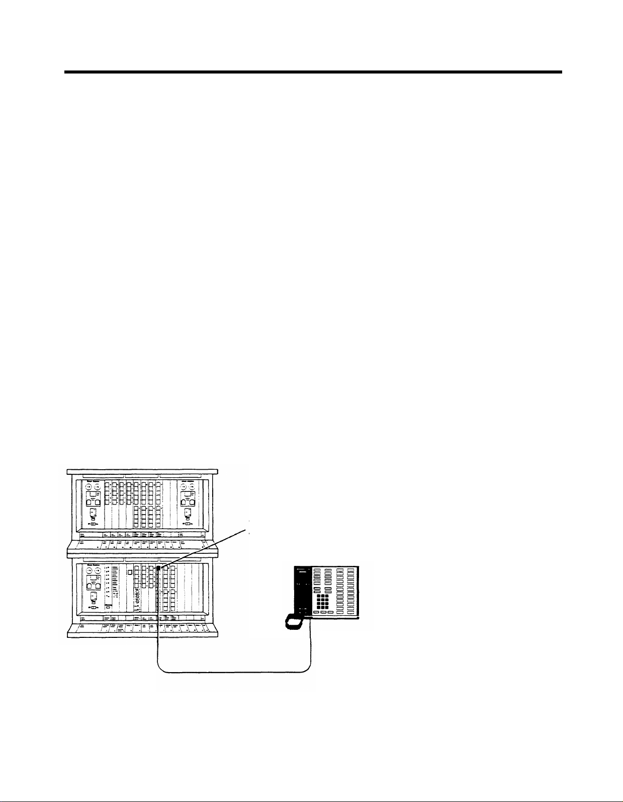
ADMINISTERING YOUR SYSTEM FOR THE FIRST TIME
System administration involves a series of simple procedures that you perform at
the control unit and at the administrator/attendant console (the voice terminal con-
nected to the intercom 10 jack on the control unit). The
to be up and running with a minimum amount of administration. However, depend-
ing on the conditions of your communications environment or the options you choose,
certain administration procedures may be required to set up a newly installed system.
Before attempting any other procedures, you must review the information in “Basic
Administration,” page 21, and complete the procedures that apply to your system
and business needs. Most administration procedures, however, are optional, depend-
ing on which features you want to use in your business; these features are described
in “Customizing with Additional System Options,” page 33.
MERLIN
system is designed
Expansion Unit
Model 1030 Control Unit
Voice Terminal Module
Jack 10
Administrator/Attendant
Console
3
Page 5

There are some features that you may want to assign to certain voice terminals
yourself because they influence call-handling throughout your entire business.
Assigning these features does not involve administration procedures, but rather, simple programming procedures at individual voice terminals. These procedures are
described in “Programming Voice Terminals for Office Priorities,” page 41. Finally,
if you want to help people program their voice terminals to meet their individual needs,
follow the procedures outlined in “Programming Voice Terminals for Personal
Priorities,” page 48. Later, if your needs change, you can always alter any system
administration or programming that has been done.
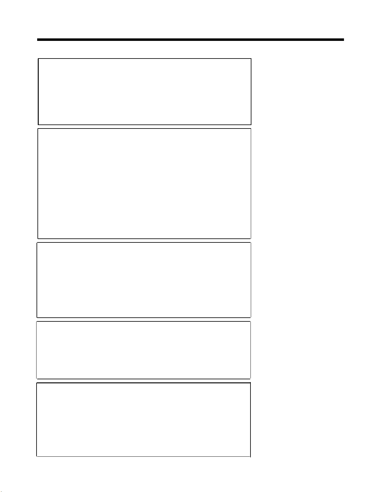
The chart on the following page shows the four types of procedures described in this
manual. If you are about to perform system administration for the first time, be sure
to read “Preparing to Administer Your System,” page 13, before you attempt any
procedures.
MAKING CHANGES TO YOUR SYSTEM LATER
Changes to system features that are administered from the administrator/attendant
console or programmed at individual voice terminals are easiest to implement. To
make these changes after your system has been set up, go to the section of this
manual that gives the procedure for assigning the feature or option you want, and
carry out just that procedure.
Basic changes to the way your system operates—that is, changes to the switch settings on the control unit—may erase important system administration that is now in
place. Before you change any switch settings, review the information in “Changing
Your System Later,” page 24.
4
Page 6
Prepare for System Administration
These procedures help you get ready to administer your system.
●
Decide how people will access outside lines.
●
Complete and keep handy your System and Voice Terminal Configuration
Forms.
●
Schedule a time to perform administration procedures.
●
Review how to enter and leave administration mode.
Perform Basic Administration
Depending on your system requirements, some of these procedures maybe
necessary immediately after your system is installed; you can also perform
these procedures whenever you need to change your system later. Perform
these procedures at the control unit and the administrator/attendant console.
● Set your control unit.
IMPORTANT:
If you’re resetting the control unit, read "Changing Your
System Later," page 24.
●
Specify Touch-Tone or rotary dialing.
●
Set lines for toll prefix or area code only.
●
Set up line pools.
●
Assign Dial Access to Pools.
●
Assign lines and pools to buttons.
Customize with Additional System Options
These procedures are optional—perform them at the administrator/attendant
console whenever you want to add these features to your system.
●
Assign call restrictions.
●
Assign voice terminals to Group Page zones.
●
Establish Night Service.
●
Program System Speed Dial codes.
●
Administer SMDR (Station Message Detail Recording) options.
Program Voice Terminals for Office Priorities
These procedures are optional—perform them at individual voice terminals
whenever you want to give someone access to these features.
●
Assign Programmable Line Ringing for incoming calls.
●
Assign Cover buttons.
●
Assign an Automatic Line Selection sequence.
Program Voice Terminals for Personal Priorities
These procedures are optional—perform them at individual voice terminals
whenever you want to give someone access to these features.
●
Assign features to programmable buttons.
●
Assign Personal Speed Dial codes to 5- and 10-button voice terminals.
●
Use special characters in programmed dialing sequences.
●
Select a Personalized Ring.
●
Program Voice Announcement Disable.
5
Page 7
MERLIN System Components
When performing your administration tasks, you work with three components of the
the administrator/attendant console, and individual voice terminals. You may also have some optional equipment that
adds features and capabilities to your system, but does not affect system administration. The following descriptions provide
information that helps you become familiar with the components that make up your system.
For information about system installation, refer to the Installation Guide: Models 1030 and 3070.
THE MODEL 1030 CONTROL UNIT AND EXPANSION UNIT
The Model 1030 control unit provides connections for up to 10 outside lines and 30 voice terminals. The addition of an
Expansion Unit makes the ModeI 1030 control unit a Model 3070 control unit and increases system capacity to up to
30 outside lines and 70 voice terminals.
MERLIN
system: the control unit,
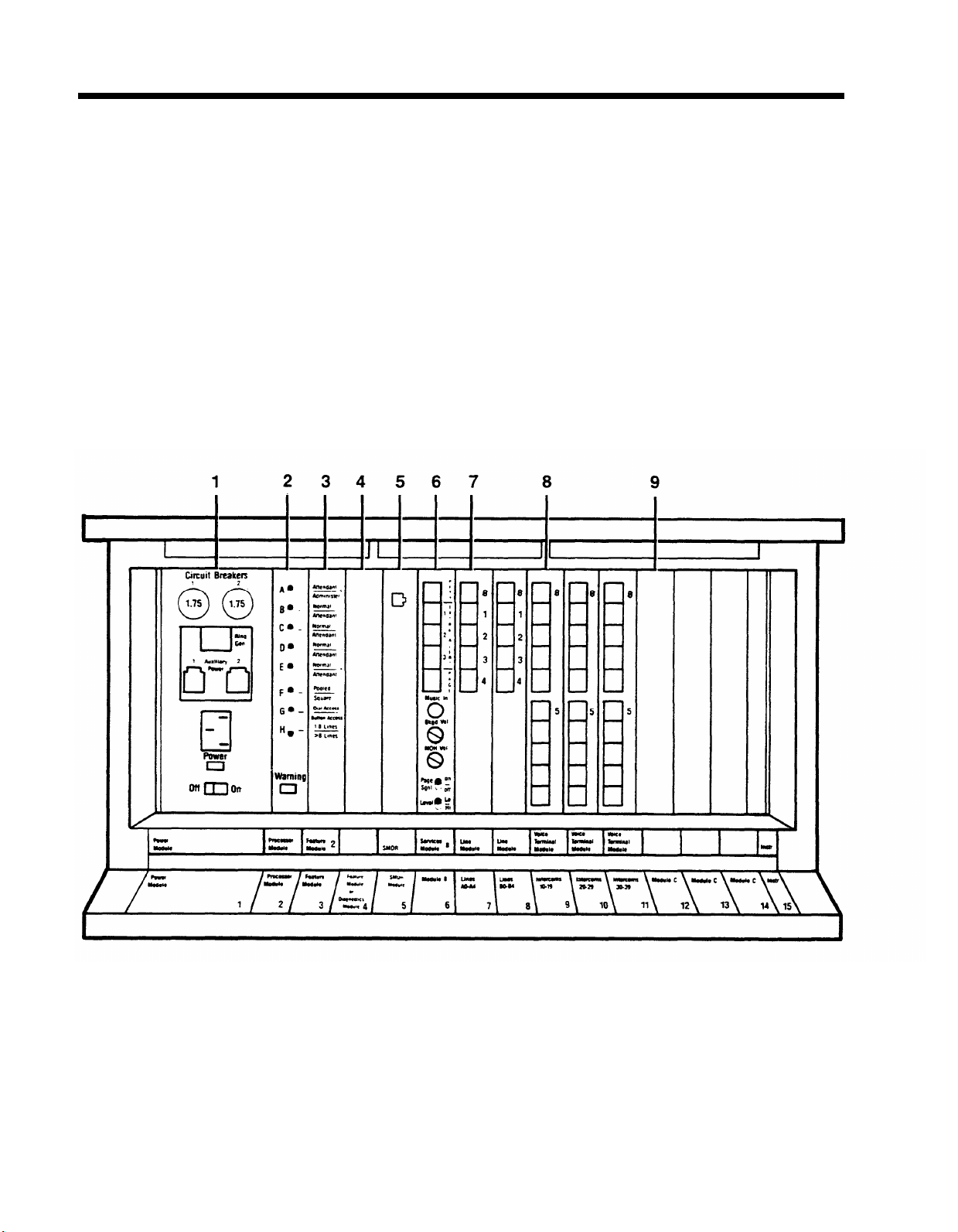
THE MODEL 1030 CONTROL UNIT
6
Page 8

1. Power Module: Reduces ac power to a level the
system can handle.
●
Circuit Breakers.
Automatically cut the power to
the control unit if an overload occurs.
●
Ring Generator jack.
Optional Ring Generator
Unit plugs in here if you have basic Touch-Tone
or rotary telephones.
●
Auxiliary Power jack.
Auxiliary Power Unit plugs
in here to provide the additional power for
systems with many optional accessories.
●
Power light.
On/Off switch.
Green light indicates power is on.
Turns the power to the control
unit on and off.
2. Processor Module: Works in conjunction with
Feature Module 2 to control system operating
conditions.
● Switches A, B, C, D, E, F, G, and H. Select
system options provided by Feature Module 2.
● Warning light. Red light warns of problem in
control unit.
3. Feature Module 2:
trols your
●
MERLIN
Attendant/Administer (Intercom 10) option.
Contains the software that con-
system.
Selects attendant or administration mode of
operation for the administrator/attendant
console.
●
Normal/Attendant (Intercoms 11, 12, 13, 14)
options. Select normal or attendant mode of
operation for these four voice terminals.
●
Pooled/Square option.
Selects mode of operation for the system so that line buttons on voice
terminals represent either groups of lines (line
pools) or separate lines (square). For detailed information on this option, see "The Square vs.
Pooled Decision;" page 14.
●
Dial Access/Button Access option.
Sets the
system so that line pools can be accessed at
voice terminals by touching a button only or by
touching a button and dialing an access code.
●
1-8 Lines/ 8 Lines option.
Sets the system size
to eight or fewer outside lines (small system) or
to more than eight lines (large system).
4. Diagnostics Module (optional):
Aids in identifying
faulty components if the system malfunctions.
5. SMDR (Station Message Detail Recording)
Module:
Allows connection of a printer so you can
use the printer to print out call traffic reports
automatically as calls are made and to issue configuration reports whenever you want them during administration procedures.
6.
Services Module B (optional):
Contains the following jacks, switches, and adjusters to connect and control optional equipment.
●
PFTT (Power Failure Transfer Telephone)
jacks. Connects four standard modular
telephones for use as backup during commercial
power outage. The system automatically
switches service to them if power fails.
●
Extra Alert jacks.
Connects strobe lights, bells,
or horns for noisy or remote locations where the
regular voice terminal ring cannot be heard.
●
Page jack. Connects a loudspeaker paging
system for up to three paging zones.
●
Music-in jack. Connects a music source for
Music-on-Hold or background music through a
paging system.
●
Bkgd Vol (Background Volume) control.
Allows
volume adjustment for background music.
●
MOH Vol (Music-on-HoId Volume) control.
Allows volume adjustment for Music-on-Hold.
●
Page Sgnl switch.
Position On provides a short
tone before loudspeaker paging announcements.
Position Off eliminates the signal.
●
Level switch. Sets amplification for music
source. Lo (up) is for sources without their own
amplifiers; Hi (down) is for those with their own
amplifiers.
7.
Line Module:
Provides jacks for up to five outside
lines. You may have one or two Line Modules in the
Model 1030 control unit and up to four additional Line
Modules in the expansion unit.
●
Jacks 0, 1, 2, 3, 4.
MERLIN
system. Line Modules have letters as
Connect outside lines to the
well as numbers. For example, the first Line
Module in the control unit is lettered A, so all the
jacks in that Line Module are called A0, A1, A2,
A3, and A4.
8.
Voice Terminal Module:
Provides jacks for ten voice
terminals. You may have up to three Voice Terminal
Modules for the Model 1030 control unit and up to four
additional Voice Terminal Modules in the Expansion
Unit. A Basic Telephone Module with jacks for basic
TouchTone or rotary telephones is also available.
●
“0” begins the numbering for the first five voice
terminal jacks on the module. These jacks (and
the location of the module) determine the inter-
com numbers of the voice terminals plugged into them. For example, if a Voice Terminal Module
is plugged into the slot labeled “Intercoms
20-29,” the jack labeled “0” is for intercom 20.
The jack below it is for intercom 21, and so on.
●
“5” begins the numbers for the second five voice
terminals.
9.
Module C (optional):
An Off-Premises Telephone In-
terface to support off-premises telephones.
7
Page 9

Addition of the Expansion Unit changes the Model 1030 control unit to a Model 3070 control unit and increases overall
system capacity to 30 lines and 70 voice terminals. The unit can accommodate:
● Up to two Power Modules
● Up to four Line Modules
●
Up to four Voice Terminal Modules
It also has two additional module slots for future use.
EXPANSION UNIT FOR MODEL 1030
8
Page 10

THE ADMINISTRATOR/ATTENDANT CONSOLE
The administrator/attendant console is the voice terminal connected to the intercom
10 Voice Terminal Module jack in the control unit. The console operates in either of
two ways:
● It functions as your primary attendant console under ordinary day-to-day
conditions.
●
It functions as the administrator console when it is used to perform many of the
procedures explained later in this manual.
To change the administrator/attendant console from one mode of operation to the
other, you simply set a switch on the control unit and then set another switch on the
console itself. When the console is in administration mode, some of its buttons take
on different functions than they do when the console is in the regular call-handling
mode. Therefore, you insert a special set of administration mode button labels in the
console so that you know which buttons to touch when you administer the system.
You will find two sets of button labels, one for a small console and another for a large
console, in the back of this manual. (See page 20 for procedures for changing modes.)
The type of administrator/attendant console you have depends on the size of your
system. In systems with 20 or fewer voice terminals or eight or fewer lines (small
systems—switch H up), the administrator/attendant console is a 34-button deluxe
voice terminal. Only a 34-button deluxe model is suitable for administering small
systems, because it has lights next to each programmable button. You use the lights
to keep track of what is happening on the lines and voice terminals you are working
with. In systems with more than eight lines or 20 voice terminals (large systems—
switch H down), the administrator/attendant console consists of a 34-button deluxe
voice terminal with an attached Attendant Intercom Selector. Only this type of console is suitable for administering a large system, because some aspects of administration require the use of the Attendant Intercom Selector. Illustrations of small and large
consoles with administration mode labels are on pages 10 and 11.
Using the Console
When you administer your system, you frequently use the Auto Intercom buttons and
Shift buttons (large systems only) on the administrator/attendant console. The
paragraphs below describe how to use these buttons.
Auto Intercom Buttons.
Each person’s voice terminal has a unique 2-digit intercom
number similar to an extension number. These intercom numbers (10 through 29 for
a small system, 10 through 79 for a large system) are automatically assigned to Auto
Intercom buttons on the console. During system administration, you use the lights
next to each Auto Intercom button to find out which call restrictions and other options are assigned to each voice terminal in your system.
Shift Buttons (large systems only).
The large console has three Shift buttons that
enable you to administer as many as 70 voice terminals by using only the 30 Auto
Intercom buttons on the Attendant Intercom Selector. When you touch one of the Shift
buttons, you change the intercom numbers assigned to the Auto Intercom buttons.
Use the left Shift button labeled 10-20-30 to select intercom numbers 10 through 39
in the blue band, the center Shift button labeled 40-50-60 to select intercom numbers
40 through 69 in the white band, and the right Shift button labeled 70-80-90 to select
intercom numbers 70 through 79 in the gray band. If you want to dial a particular intercom number, you must first touch the Shift button that provides access to the group
of intercom numbers that includes the one you want. For example, if you want to
assign lines to the voice terminal represented by intercom 31, touch the left Shift button. The light next to the Shift button comes on, and the Auto Intercom buttons now
represent intercom numbers 10 through 39.
9
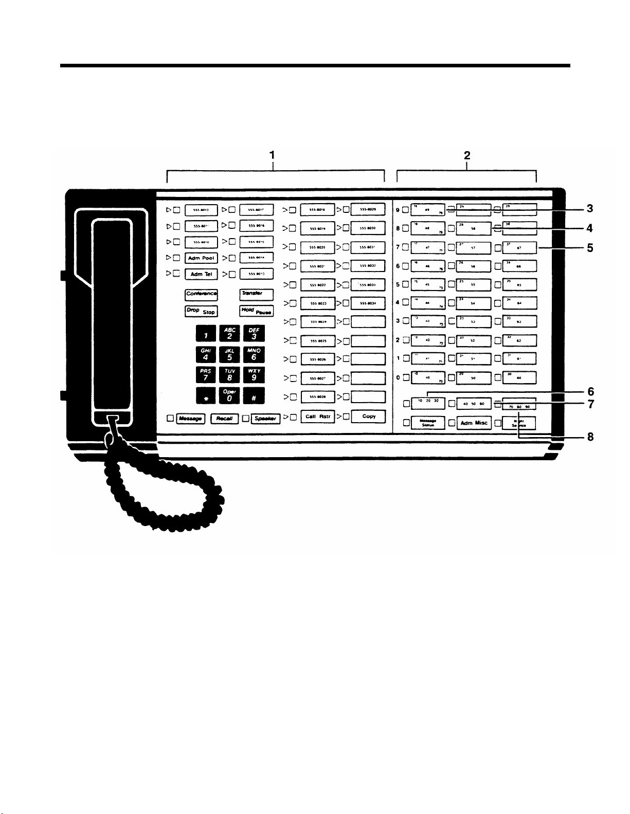
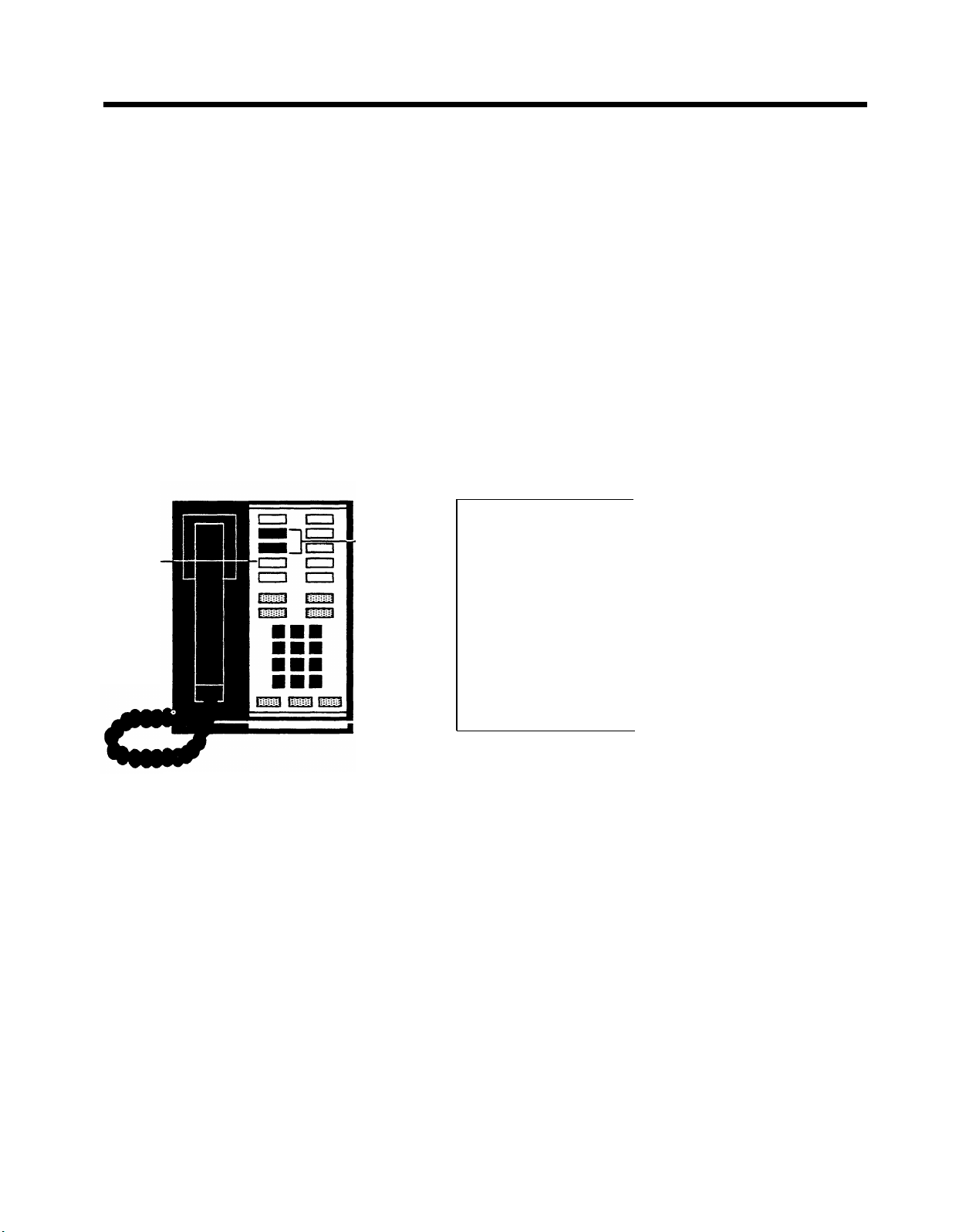
Page 11
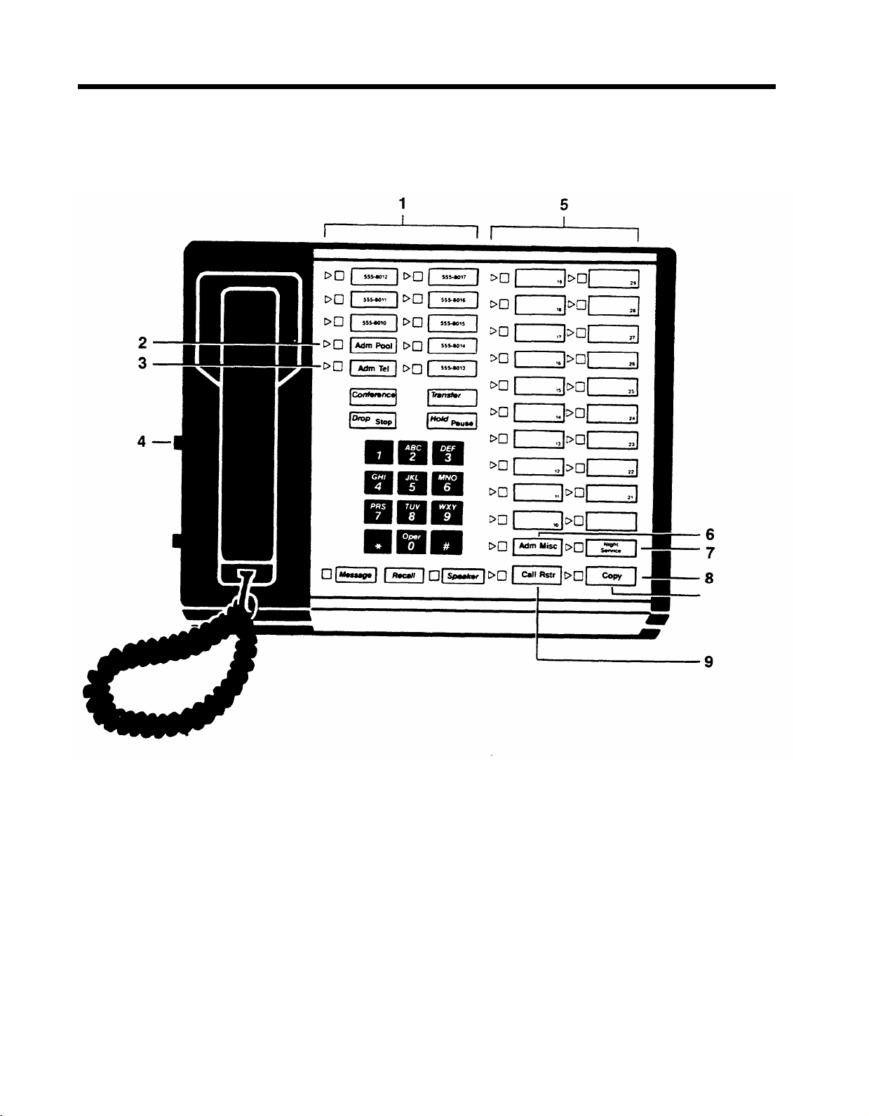
Small Administrator/Attendant
Console* in Administration Mode
1. Line buttons.
2.
Touch
Adm Pool
3.
Touch
Adm Tel
and assigning voice terminals Dial Access to Pools.
4.
Set the T/P switch to P during system administration.
5.
Auto Intercom buttons (10 through 29).
6.
Touch
Adm Misc
dialing, assigning allowed-list call restrictions, and administering other system options.
*
For systems with 8 lines or fewer or with 20 or fewer voice terminals—switch H up on control unit.
10
when setting up line pools.
when assigning lines to voice terminals
when specifying TouchTone or rotary
7.
Touch
Night Service
extra-alerting devices when attendant is off duty.
8. Touch Copy to give a voice terminal the same
assignments as one that has already been set up.
9.
Touch
Call Rstr
code only and assigning outward and toll call restrictions to voice terminals.
when assigning lines to activate
when setting lines for toll prefix or area
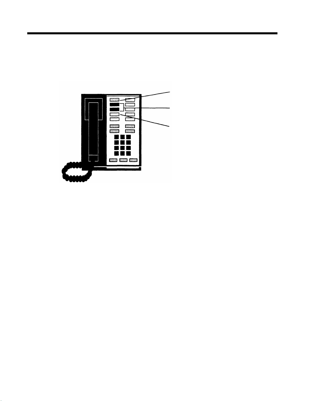
Page 12
Large Administrator/Attendant
Console* in Administration Mode
The large console provides the same features as the small console but it has more lines and Auto Intercom buttons.
1. Line buttons.
2.
Auto Intercom buttons (10 through 79).
3. Buttons in this column represent intercom numbers
10-19, 40-49, or 70-79, depending on which Shift button you touch.
4. Buttons in this column represent intercom numbers
20-29 or 50-59, depending on which Shift button you
touch.
*
For systems with more than 8 lines or more than 20 voice terminals—switch H down on control unit.
5.
Buttons in this column represent intercom numbers
30-39 or 60-69, depending on which Shift button you
touch.
6.
Touch this Shift button to use Auto Intercom buttons
for intercom numbers 10-39.
7.
Touch this Shift button to use Auto Intercom buttons
for intercom numbers 40-69.
8.
Touch this Shift button to use Auto Intercom buttons
for intercom numbers 70-79.
11
Page 13

OPTIONAL EQUIPMENT
Although you need only the control unit and the administrator/attendant console to
administer your system, you may also have optional equipment that adds features
and capabilities to your system.
●
Attendant Intercom Selector.
Provides an attendant with 30 additional Auto
Intercom buttons.
● Automatic Multipurpose Adapter. Connect manually and automatically
operated accessories to any
●
Basic Telephone and Modem Interface.
MERLIN
system voice terminal.
Connects telephones and data com-
munication devices, such as autodialers, answering machines, cordless
telephones, facsimile machines, and auto-answer or originating modems to your
MERLIN
system. You can also use a transformer to connect a timer to a Basic
Telephone and Modem Interface.
● Basic Telephone Module. Lets you connect basic Touch-Tone and rotary
telephones to the
● Hands-Free Unit. Provides you with full speakerphone capability including
MERLIN
system.
hands-free telephone conversation, On-Hook Dialing, Monitor-on-Hold, and
teleconferencing. The unit requires a programmable button on the voice ter-
minal if you want it to go on automatically when intercom calls ring at the voice
terminal.
●
Headset and Headset Adapter.
Enable an attendant to answer and listen to
calls without lifting the handset.
●
Manual Multipurpose Adapter.
cessories, such as computer modems, to any
●
Off-Premises Telephone Interface.
MERLIN
system.
Allows you to connect manually operated ac-
MERLIN
system voice terminal.
Connect off-premises telephones to your
12
Page 14

Preparing to Administer Your System
Before you start to administer your system, review this section to make sure you have
the information and completed forms that you need.
Preparation Procedures
●
Decide how people will access outside lines.
●
Complete your System and Voice Terminal Configuration Forms.
●
Schedule a time to perform administration procedures.
●
Review how to enter and leave administration mode.
13
Page 15
THE SQUARE VS. POOLED DECISION
For systems that have just been installed, you have to make a decision about a basic
system characteristic—
how people access outside lines with their voice terminals.
You have the option of setting your system to be either square or pooled. In a square
system, each outside line appears on a separate button at each voice terminal. In
a pooled system, outside lines are grouped together so that one button provides
access to several outside lines. On attendant consoles, however each outside line
appears on a separate button, whether your system is pooled or square.
Whether your system should be square or pooled depends on several factors, including the number of outside lines that you have, the number of people in your
business, and the types of voice terminals in your system. The characteristics of both
configurations are discussed in greater detail in the paragraphs that follow.
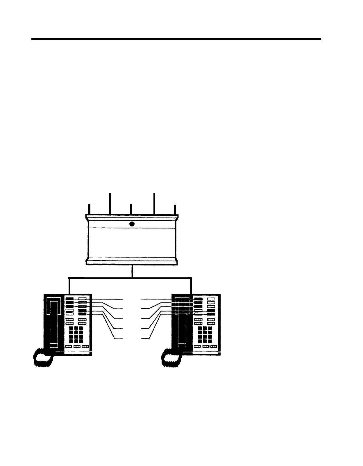
About Square Systems
In a square configuration, every outside line is represented by a separate button in
the same position on every voice terminal in the system (see diagram below), except for those voice terminals with too few buttons to accommodate all the lines. (See
"Special Information about 5-Button Voice Terminals," page 61.)
Line B Line D
Line A
Line C
Line C
Line B
Line A
Line E
Line D
Line E
SIMPLE SQUARE SYSTEM
A square arrangement simplifies call handling, because people can join in on calls
or pickup calls on hold just by touching the appropriate line button at any voice terminal. Generally, however, square systems are practical only if you have eight or fewer
outside lines because only the buttons above the dial pad can be used as line buttons. On 10- and 34-button voice terminals, you can assign a maximum of eight line
buttons; on 5-button voice terminals, only three buttons are available for this purpose.
14
Page 16
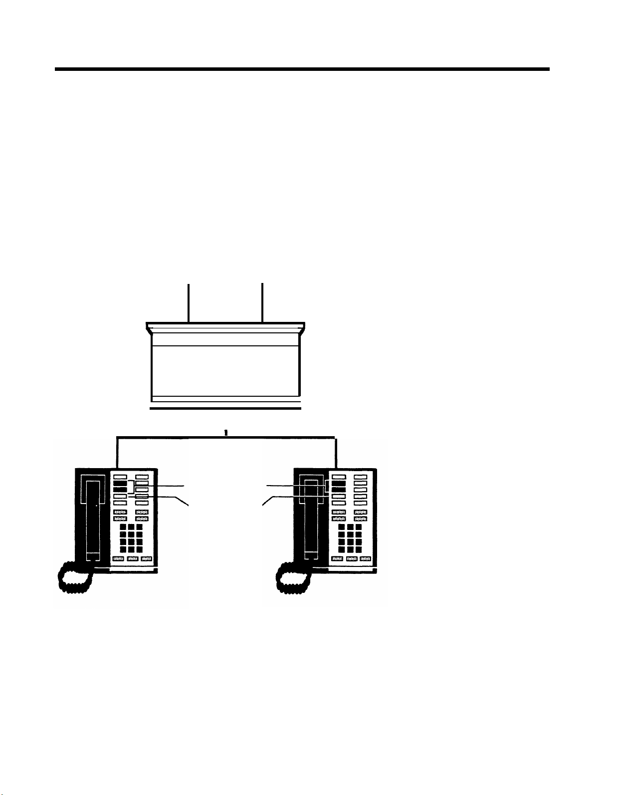
About Pooled Systems
In a pooled configuration, you group several outside lines together into a pool that
people can access with a single button on their voice terminals. Your system can
have as many as 11 different line pools, and in fact, you will probably want to have
more than one pool if you have many special-purpose lines, such as WATS or Foreign
Exchange (FX) lines. Each line in a pool should be interchangeable with all other
lines in that pool because you cannot control which line people get when they access
a pool.
When assigning lines in a pooled system, you can assign any number of lines to a
single pool (see diagram below), but you cannot assign any line to more than one
pool. By the same token, you do not need to assign all your lines to pools; you can
also assign individual lines that are not included in any pool to any voice terminal
in your system. A diagram of a pooled system with eight lines appears on page 16.
Line B
Line A
I I I
Line C
Line D
●
Lines A, B, C, D, & E pooled
Lines A, B, C, D, & E
pooled
lntercom-Voice
Line E
SIMPLE POOLED SYSTEM
15
Page 17
A pooled configuration is recommended for systems with more than eight lines, since
eight is the maximum number of line buttons that a square system accommodates.
Line use is very efficient in a pooled system, so you may need fewer outside lines
than you would with a square system. Furthermore, more programmable buttons on
voice terminals are available for assignment as special-purpose line buttons or
feature buttons.
Attendant console
Line not assigned to pool = Line D
Line C
Line B
Line A
Intercom-
Voice
Intercom-
Ring
Main pool = Lines A, B, C
Line Pool 2
Line pool 3 = Lines G, H
= Lines E, F
Line H
Line G
Line F
Line E
Line D
Voice terminal 1
16
Line pool 3
Main pool
Intercom-
Voice
Line D
Main pool
Intercom- Intercom-
Voice
Voice terminal 2
POOLED SYSTEM WITH 8 LINES
Voice terminal 3
Line pool 2
Main pool
Voice
Page 18
Button Access vs. Dial Access to Pools.
You can choose one of two access op-
tions for line pools: Button Access to Pools or Dial Access to Pools. If your system
has several line pools, Dial Access is advantageous because it uses only two but-
tons on each voice terminal to provide access to all pools. Dial Access is necessary
if you want basic telephones to have access to pools or special lines. Dial Access
is also necessary if you want 5-button voice terminals to have access to more than
one special line or pool. Dial Access is practical only if you have several line pools,
so if you have only one or two line pools, Button Access is the best option for your
system.
With the Dial Access option (see the diagram below), you arrange the system so that
people can access any line pool by lifting the handset, touching one of the two buttons above
Intercom-Voice,
and dialing the access code assigned to the pool (9 for
the main pool, or 890 through 899 for the others). But even if you set your system
for Dial Access, you can still assign some pools to buttons, if you like. When you have
Dial Access to Pools, all incoming calls (with the exception of those coming in on lines
and pools assigned to buttons) ring and flash only at the attendant console and must
be transferred to the appropriate person.
— Pools —
IntercomVoice
Dial code 893
Dial code 892
Dial code 891
Dial code 890
Dial code 9
= Line pool 5
= Line pool 4
= Line pool 3
= Line pool 2
= Main pool
DIAL ACCESS TO POOLS
17
Page 19
With the Button Access option (see the diagram below), people access all line pools
directly through pool buttons on each voice terminal. In such an arrangement, the
first two buttons above Intercom-Voice provide access to the main pool. You may
assign additional buttons for access to other pools that may include WATS lines,
Foreign Exchange (FX) lines, or lines used for special purposes.
Additional
line pool
Main
pool
Intercom-Voice
BUTTON ACCESS TO POOLS
18
Page 20

THE FORMS AND LABELS YOU NEED
Before you begin performing administration procedures, be sure to complete all the
necessary forms:
●
A System Configuration Form to keep a record of how the lines in your system
are arranged.
●
Voice Terminal Configuration Forms to record the lines and features assigned
to all voice terminals. Fill out one of these for each voice terminal.
When you ordered your system, you should have filled out these forms in the process of competing the
MERLIN
Communications System Planning Guide: Models
1030 and 3070. If you did not, turn to the Appendix, copy the forms included there,
and fill them out before you proceed further. These forms serve as important
references throughout later system administration procedures.
During system administration, the buttons on the administrator/attendant console
perform completely different functions than they do when the console is being used
to handle calls. Therefore, you need a different set of button labels whenever you
use the console for system administration. Two sets of preprinted administration mode
button labels are in the back of this document: one set for an administrator/
attendant console in systems with switch H on the control unit set to eight or fewer
lines, and one set for an administrator/attendant console in systems with switch H
set to more than eight lines. Keep the labels and completed forms to use whenever
you administer your system.
CHOOSING A TIME TO ADMINISTER YOUR SYSTEM
Before you begin administration procedures, choose a time when you do not expect
many people to be using their voice terminals. When you perform some administration procedures, the system blocks all tails on the lines or voice terminals with which
you are working. Blocked voice terminals generate soft, periodic beeps to alert peo-
pie that they cannot use them. If you accidentally try to administer a voice terminal
that has an active call, you do not cutoff the caller. Rather, you are unable to to continue administering that voice terminal until it is idle.
19
Page 21
ADMINISTRATION MODE
Administration mode is an operating state of your control unit and of your
administrator/attendant console that is very different from their everyday state of
operation. With the system in administration mode, you are able to set up or change
systemwide options or features. When you put the system into administration mode,
the buttons of the administrator/attendant console take on entirely different functions
from those they perform when the console is in the regular call-handling mode.
Entering and Leaving Administration Mode
You must enter administration mode whenever you use the attendant console to administer your system. The boxed instructions below tell you how to enter administration mode.
Entering Administration Mode
1. Set switch A on the Processor Module of the control unit to Administer
(down).
2. Insert the administration mode button labels (see the back of this document)
in the administrator/attendant console.
3. Slide the T/P switch on the left side of the console to P.
Red and green lights start flashing next to the administration mode buttons
labeled
When you finish administration procedures at the console, you must leave administration mode to resume normal operation. Do this when you complete your initial system
administration and whenever you complete any system changes in the future. The
boxed instructions below tell you how to leave-administration mode.
Adm Pool, Adm Tel, Adm Misc, Call Rstr,
and
Night Service.
Leaving Administration Mode
1. Slide the T/P switch to the center position.
2. Set switch A on the Processor Module of the control unit to Attendant (up).
3. Remove the administration mode button labels from the console and insert
the regular call-handling labels used by the attendant.
20
Page 22

Basic Administration
Once your system planning and paperwork are complete, you can perform basic ad-
ministration procedures. The chart below summarizes the procedures described in
this section. Remember that if you are administering a new system that has just been
installed, some of these basic procedures maybe required to set the proper operating
conditions for your particular environment, and you must perform them first before
you goon to do any other system administration. Carry out the procedures in the
order listed in the chart, but keep in mind that you may not need to perform ail of them
to customize your system to your particular environment. Read each procedure first
to see if it applies to you.
IMPORTANT:
Whenever you perform any administration procedures, remember to
choose a time when you do not expect many people to be using their voice terminals.
Basic Administration
● Set your control unit.
●
Specify Touch-Tone or rotary dialing.
●
Set lines for toll prefix or area code only.
● Set up line pools.
●
Assign Dial Access to Pools to voice terminals.
●
Assign lines and line pools to buttons.
21
Page 23

SETTING YOUR CONTROL UNIT
The first step in customizing the
MERLIN
operating conditions you select.
system is to set the control unit to the
IMPORTANT:
If your control unit has been set previously and you just want
to change the setting of a particular switch, be sure to read "Changing Your
System Later," page 24, before resetting the switch.
Follow these steps to set your control unit:
1.
Turn off the control unit by setting the On/Off switch on the Power Module
to Off.
2.
Set switch A to Administer (down).
Set switch A to this position whenever you need to customize your system
from the administrator/attendant console. When you finish customizing, set
switch A to Attendant (up).
NOTE: Switch A is the only switch on the control unit that you can reset
with the power on. If you reset any other switch with the power on, the con-
trol unit does not record any of the changes you make.
3.
Set switches B through E.
Switches B through E control intercom numbers 11 through 14, respectively.
You can designate any of these four voice terminals as attendant consoles.
If you designate a voice terminal to function as an attendant console, each
outside line appears on a separate button, regardless of whether you select
the pooled or square option.
The four voice terminals selected by switches B through E plus the administrator/attendant console (intercom 10) provide a maximum of five attendant consoles if you need them.
●
For those voice terminals that function as attendant consoles, set the
switch to Attendant (down).
●
For those voice terminals that function as regular telephones, set the
switch to Normal (up).
4.
Set switch F.
●
If you have chosen to pool your lines, set switch F to Pooled (up).
IMPORTANT:
If you are resetting this switch from Square to Pooled, be
aware that you erase all system line administration and voice terminal
programming that is now in place.
●
If you want every outside line to appear on a separate button, set switch
F to Square (down) and go to step 6.
5.
Set switch G.
● If switch F is set to Pooled and you have decided to arrange your
system so that people can access a line pool directly by simply
touching a button on a voice terminal, set switch G to Button Access
(down).
● If switch F is set to Pooled and you have decided to arrange your
system so that people can access any line pool by dialing an access
code, set switch G to Dial Access (up).
NOTE:
If switch F is set to Square, switch G may be set to either posi-
tion without having any effect on the system.
22
Page 24

6. Set switch H.
●
If you have eight or fewer outside lines and 20 or fewer voice terminals,
set switch H to 1-8 Lines (up).
NOTE:
The switch setting you select does not always have to correspond to the number of outside lines you actually have. For example,
if you have eight or fewer lines, but plan to grow beyond eight lines
within a year or two, you might be wise to set switch H to > 8 Lines
(down) in order to simplify administering the system later. If you change
the setting of this switch later, you cancel any special line administra-
tion or programmed features on your attendant consoles..
●
If you have more than eight outside lines or more than 20 voice terminals, or if you expect your system to grow to this size in the next year
or so, set switch H to > 8 Lines (down).
7. If your system has an SMDR (Station Message Detail Recording) Module
and a printer with an RS-232 connector, connect the printer to the SMDR
Module (refer to the instructions that come with the module).
8. If your system has a Services Module, make the following adjustments.
Otherwise, go to step 9.
●
If you have background music through a loudspeaker paging system,
you can adjust its volume by turning the Bkgd Vol control clockwise
to raise the volume, or counterclockwise to lower it. If you do not have
background music through a loudspeaker paging system, turn the
control counterclockwise as far as it goes.
●
If you have Music-on-Hold, you can adjust its volume by turning the
MOH Vol control clockwise to raise the volume, or counterclockwise
to lower it. If you do not have Music-on-Hold, turn the control
counterclockwise as far as it goes.
●
If you have a music source with its own amplifier, set the Level switch
to Hi (down); otherwise, set the switch to Lo (up).
●
If you have a loudspeaker paging system and want a short tone to
precede loudspeaker announcements, set the Page Sgnl switch
to
On
(up). Otherwise, set the switch to Off (down).
9. Turn on the control unit by setting the On/Off switch on the Power Module
to On. This causes the system to record the settings you just made.
10. If you are setting up a new system for the first time, enter administration
mode, as described on page 20, and continue following the procedures in
this chapter.
23
Page 25

CHANGING YOUR SYSTEM LATER
Basic changes to the way your system operates—that is, changes to the switch set-
tings on the control unit—may erase important system administration that is now in
place. To change switch settings, go to “Setting Your Control Unit,” page 22, and
follow the instructions for the switch you want to reset. Since you will be skipping
steps in these instructions, you must be sure not to skip any that are required. Follow
the general instructions below to prevent this from happening.
General instructions for resetting control unit switches:
1. Set the On/Off switch in the Power Module to Off.
2. Set switch A to Administer (down).
3. Follow the instructions for the switch you intend to reset.
4. Set the On/Off switch in the Power Module to On.
5. Perform any required readministration or reprogramming discussed below
in “Notes on Resetting Control Unit Switches.”
6. Set switch A back to Attendant (up).
Notes on Resetting Control Unit Switches
Whenever you change the setting of a switch on the control unit, you will probably
have to make other changes in your system. Keep the following in mind:
●
If you add or remove attendant consoles (switches B through E), you have to
reassign special lines and features to the voice terminals whose function you
have just changed.
●
If you change the setting of the Pooled/Square switch (switch F), you erase all
system line administration and voice terminal programming that was formerly in
place. You have to completely readminister all your lines, setup pools and Dial
Access to pools, if these apply, and reprogram all your voice terminals.
●
If you change the setting of the 1-8/>8 switch (switch H), you cancel any special
line administration or programmed features on your attendant consoles. The
setting of this switch determines how the system automatically assigns lines
and intercom numbers to the buttons on attendant consoles. It also determines
the function of certain buttons on the attendant/administrator console when the
console is in administration mode (see the initial feature charts on pages 59 and
60). Note that the switch setting you select does not always have to correspond
to the number of outside lines you actually have. For example, if you have eight
or fewer lines, but plan to grow beyond eight lines within a year or two, you might
be wise to set switch H to >8 in order to simplify administering the system later.
24
Page 26

SPECIFYING TOUCH-TONE OR ROTARY DIALING
When your system is installed, it is set to receive Touch-Tone signals, so if some of
your lines are rotary, you need to reset your system accordingly. To determine if your
lines are Touch-Tone or rotary, go to the administrator/attendant console and make
sure that the T/P switch is in the center position. Then touch each line button and
dial out. If a line is Touch-Tone, you hear tones and the dial tone stops. If a line is rotary,
you hear tones but the dial tone is not interrupted. Follow the procedure below to
specify Touch-Tone or rotary dialing.
1.
If you have not already done so, enter administration mode by following the
boxed instructions on page 20.
2.
Touch
Adm Misc.
The lights next to the administration mode buttons stop flashing and the green
light next to
3.
Dial #302.
4.
One by one, touch the line button for each line in your system until the green
light beside it shows the appropriate code. Each successive touch of a button
gives you one of the following codes:
Touch
5.
The lights next to the administration mode buttons flash again.
6.
Continue to administer your system or leave administration mode by following the boxed instructions on page 20.
Adm Misc
Steady green on = Touch-Tone dialing
Adm Misc.
remains on.
Green off
= rotary dialing
25
Page 27

SETTING LINES FOR TOLL PREFIX OR AREA CODE ONLY
If you plan to restrict any voice terminals to local calls only, you must perform this
procedure. When your system is first installed, it is automatically set to detect a toll
prefix (0 or 1) when people dial a long distance call. However, if you are in an area
of the country in which people need not dial a toll prefix before placing long distance
calls, you must follow the procedure below to set your system to detect area codes
only. The system can then detect calls properly.
1. If you have not already done so, enter administration mode by following the
boxed instructions on page 20.
2. Touch
3. One by one, touch each line button until the green light next to it shows the
4. Touch
The lights next to the administration mode buttons flash again.
5. Continue to administer your system or leave administration mode by follow-
ing the boxed instructions on page 20.
Call Rstr.
The lights next to the administration mode buttons stop flashing, and the green
light next to
appropriate code. Each successive touch of a button gives you one of the
following codes:
Call Rstr
Steady green on = toll prefix
Call Rstr.
remains on.
Green off
= area code only
26
Page 28

SETTING UP LINE POOLS
If you plan to pool the lines in your system (as discussed in the section, “The Square
vs. Pooled Decision,” page 14), you must designate the lines in each pool. Before
you set up your line pools, please read the information below.
●
Whenever you set switch F on the control unit to Pooled and set switch G to either
Button Access or Dial Access, the system automatically assigns all lines to the
main pool. You must remove any lines that you do not want in this pool. You can
assign these lines to other pools or use them as individual lines.
●
Do not mix different types of lines. For example, do not put regular telephone
company lines and WATS lines in the same pool. All lines in a pool must be interchangeable, since people cannot tell which lines they are on when they use
the pool.
●
Assign the type of line most commonly used throughout your business to the
main pool. In most cases, these are regular telephone company lines, but in
some cases they might not be. For example, if most of the calls made in your
business are long distance, you may want the main pool to consist of WATS lines
instead of regular lines.
●
The number of lines available for pooling is affected by the number of lines you
must reserve for personal or special-purpose use. For example, if you have ten
outside lines and two people need personal lines, there are eight lines left for
pooling.
●
You can have up to 11 pools, with as many lines as you like in each pool. However,
a line cannot be in more than one pool. If you have Dial Access to Pools, people can access a particular pool by dialing the code assigned to the code (9 for
the main pool, 890 through 899 for additional pools).
Now, follow the procedure below.
1.
If you have not already done so, enter administration mode by following the
boxed instructions on page 20.
2.
Touch
Adm Pool.
The lights next to the administration mode buttons stop flashing and the green
light next to
Adm Pool
remains on. The console gives a 2-beep signal for
you to begin.
If the light flashes rapidly instead, your lines are in use. Wait until the system
signals you to begin, or try again later.
3.
You are now administering the main pool, the one people access by dialing 9. A steady red light next to any line button means the line is currently
assigned to the main pool. Refer to your completed System Configuration
Form to see which lines you want to have in the main pool. Touch the button of any line showing a steady red light that you do not want in the pool.
The red light goes off, confirming that the line is no Ionger part of the pool.
If you want a line in the main pool but the red light beside it is off, touch the
4.
line button.
A steady red light comes on next to the line button, confirming that the line
is now in the pool.
NOTE:
If a line is already in another pool, you hear a beep. You must remove
the line from the other pool before you can assign the line to the pool you
are administering.
5.
To administer any of the additional pools, dial the appropriate access code
(890 through 899), and repeat steps 4 and 5 after dialing each code. To return
to pools you’ve already administered:
●
If you want to administer the main pool again, dial 9.
● If you want to administer one of the other pools again, dial the ap-
propriate access code (890 through 899).
Touch
6.
Adm Pool.
The lights next to the administration mode buttons flash again.
7.
Continue to administer your system or leave administration mode by following the boxed instructions on page 20.
27
Page 29

ASSIGNING DIAL ACCESS TO POOLS
If you have a pooled system and switch G on the control unit is set to Dial Access
(up), you can assign voice terminals Dial Access to Pools. For an explanation of this
option, see “Button Access vs. Dial Access to Pools,” page 17. With this arrangement, a person can access any line pool by lifting the handset and dialing an access code for the pool (9 for the main pool, 890 through 899 for additional pools).
Follow the procedure below to assign voice terminals Dial Access to Pools.
1. If you have not already done so, enter administration mode by following the
boxed instructions on page 20.
2. Touch
Adm Tel.
The lights next to the administration mode buttons stop flashing, and the
green light next to
Adm Tel
remains on.
Red lights come on next to the buttons of each line assigned to any of the
pools.
3. Dial the intercom number or touch the Auto Intercom button for the voice
terminal to which you want to assign Dial Access to Pools.
A green light comes on next to the Auto Intercom button representing the
voice terminal, and the console gives a 2-beep signal for you to begin.
Green lights come on next to the buttons of any lines already assigned to
this voice terminal.
If the green lights beside both the Auto Intercom button and
Adm Tel
flash
rapidly instead, the voice terminal is in use. Wait until the green lights
become steady, or try again later.
4. Touch the same Auto Intercom button again.
Steady red and green lights come on next to
Adm Tel.
5. Refer to your completed Voice Terminal Configuration Form to see which
pools require Dial Access. Then touch any buttons that show steady green
lights and represent lines that are in pools to which you do not want this voice
terminal to have access. Keep in mind that the lines in a pool always change
as a group. Touching any button representing a line in a pool affects a//the
lines in that pool.
The green lights go off, indicating that the voice terminal no Ionger has Dial
Access to these lines and the pools that they are in.
6. Touch any buttons that do not show steady green lights and that represent
lines that are in pools to which you do want this voice terminal to have Dial
Access.
The green lights come on, indicating that the voice terminal has Dial Access
to the lines and the pools that they are in.
7. Repeat steps 3 through 6 for each voice terminal to which you want to assign
Dial Access to Pools.
If you want to give a voice terminal the same Dial Access assignments as
one that has already been set up, use this shortcut:
●
Dial the intercom number or touch the Auto Intercom button of the new
voice terminal on which you want to copy line assignments.
●
Touch
Copy.
●
Dial the intercom number or touch the Auto Intercom button of the voice
terminal whose assignments you want to copy.
NOTE:
When you copy the Dial Access assignments, you also copy call
restrictions, allowed-list permissions, and line and pool assignments.
8. Touch
Adm Tel.
Lights next to the administration mode buttons flash again.
9. Continue to administer your system or leave administration mode by follow-
ing the boxed instructions on page 20.
28
Page 30

ASSIGNING LINES AND LINE POOLS TO BUTTONS
You can assign and reassign individual lines and line pools to buttons other than
the two regular pool buttons on voice terminals whenever necessary. Before you
assign lines and line pools to buttons, please read the following information:
●
If you have a pooled system and you assign a line that is in a pool to a separate
button on a voice terminal, you are assigning all the lines in that particular pool
to the button. Therefore, if you want to assign a certain pool, such as a WATS
line pool, to a separate button, you can do so by assigning any line in the pool
to the button. You can do this whether switch G on the control unit is set to But-
ton Access or Dial Access.
●
Note that none of the voice terminals in your business come with preprinted button labels. Any lines or line pools that you assign have to be labeled on the voice
terminal buttons, as do any initial features (see the initial features diagram, pages
42 and 43) or features you assign.
●
If someone regularly covers calls that come in on another person’s line (for example, a secretary who answers someone’s private line), try to assign that line
to both people. If you can’t, program a Cover button on the first voice terminal
(see page 46). Keep in mind, however, that a Cover button covers all calls that
come in on the covered voice terminal, not just calls on a specific line.
●
If you have a pooled system, you may not want certain voice terminals to use
the pools accessed by the two regular pool buttons above the intercom buttons.
If so, you can remove the pools from the voice terminal. The pool buttons are
then used only to receive transferred calls. You cannot assign any other features
to these buttons.
●
If you want to remove a line pool that is assigned to a button on any voice terminals, you must remove the pool from the button before removing the lines from
the pool. This leaves the button free for other custom features.
●
If you have off-premises telephones, see “Special Information about Basic
Telephones,” page 62.
●
Always assign lines and line pools to one voice terminal at a time. Make sure
you have a completed Voice Terminal Configuration Form for each voice
terminal.
●
Lines are assigned to buttons on the attendant console according to how they
are plugged into the control unit. Each button on the console corresponds to
a different jack in a Line Module (see the initial features diagrams, pages 59
and 60). For example, lines A0, A1, A2, A3, and A4 correspond to the lines plugged into jacks 0 through 4 in Line Module A0-A4.
●
If your system is square and you have many people using 5-button voice terminals, make sure the lines they need to use are plugged into jacks A0, A1, and
A2 on the control unit. You cannot assign lines plugged into other jacks to
5-button voice terminals.
●
Even though you may not be using the full capacity of a Line Module in the control unit, the lines represented by the empty jacks are automatically assigned
to buttons on the attendant console. Remove these lines so that the buttons can
be used for custom features.
29
Page 31

Now, follow the procedure below.
1. If you have not already done so, enter administration mode by following the
boxed instructions on page 20.
2. Touch
Adm Tel.
The lights next to the administration mode buttons stop flashing and the green
light next to
Adm Tel
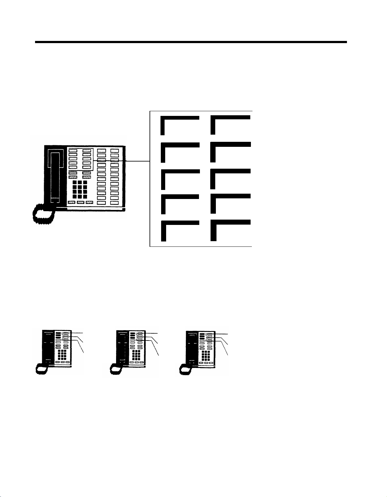
remains on.
If you have a pooled system, the red light comes on next to the line buttons
for each line in the pool.
A pooled system automatically assigns pooled lines to the two buttons above
Intercom-Voice on every voice terminal except attendant consoles, as
shown in the diagram.
Pool
Pool
Intercom
Voice
Intercom
Ring
3. Dial the intercom number or touch the Auto Intercom button of the voice terminal to which you want to assign lines or line pools.
A steady green light comes on next to the Auto Intercom button for the voice
terminal whose lines you are assigning, and the console gives a 2-beep signal
for you to begin.
Steady green lights come on next to the buttons of any lines already assigned
to this voice terminal.
If the green lights beside both the Auto Intercom buttons and
Adm Tel
flash
instead, the voice terminal whose lines you want to assign is in use. Wait
until the green lights become steady, or try again later.
30
Page 32

4.
Refer to the Voice Terminal Configuration Form to see what lines and line
pools you plan to assign to this voice terminal. Make sure there are no green
lights beside buttons representing lines that you do not want this voice terminal to use. If any are on, touch the button for each line you want to remove.
The green light next to each button goes off, confirming that the line no longer
appears at the voice terminal.
Touch any line button that is not showing a green light, but that you want
5.
assigned to the voice terminal. If you have a pooled system, you must touch
the buttons in a certain order (see the note below).
The green light goes on, confirming that the line now appears at a button
on the voice terminal.
If the line is in a pool, the pool now appears on a button at the voice terminal,
and the red and green lights go on next to the buttons for each line in the
pool.
NOTE:
In a square arrangement, the system automatically assigns each
line to the same button on every voice terminal. When you are assigning
lines or line pools to buttons other than the two regular pool buttons in a
pooled system, however, the order in which you touch the line buttons on
the console determines the order in which lines are assigned on a voice
terminal. The numbers in the diagram below show the order in which the
system automatically assigns lines to the buttons above and to the right of
the two regular pool buttons. If you use the Button Access to Pools option,
the system assigns pools other than your main pool to buttons in the same
order. You can change the order in which lines and pools appear on a voice
terminal by removing all lines and pools from the voice terminal. Then touch
the line buttons in the order you want to assign the lines and pools.
Pool
Pool
Intercom
Voice
Intercom
Ring
1
6
5
4
3
2
31
Page 33

6. Follow steps 3 through 5 of this procedure for each voice terminal in your
system.
If you want to give a voice terminal the same line assignments as one that
has already been set up, use this shortcut:
●
Dial the intercom number or touch a Shift button (large systems only)
and touch the Auto Intercom button of the voice terminal to which you
want to copy line assignments.
●
Touch
Copy.
●
Dial the intercom number or touch a Shift button (large systems only)
and touch the Auto Intercom button of the voice terminal whose
assignments you want to copy.
NOTE:
When you copy the line assignments, you also copy call restrictions,
Dial Access to Pools, and pool assignments.
7. Touch Adm Tel.
The lights next to the administration mode buttons flash again.
8. Continue to administer your system or leave administration mode by follow-
ing the boxed instructions on page 20.
32
Page 34

Customizing with Additional System Options
Once basic administration is completed, you can assign additional options to your
system. Among these options are Call Restriction, Group Page, Night Service,
System Speed Dial, and various SMDR (Station Message Detail Recording) options.
The chart below summarizes the procedures described in this section. You may not
need to perform all of them to meet your immediate business needs. Read each procedure first to see if it applies to you.
Customize with Additional System Options
●
Assign call restrictions to voice terminals:
— Assign outward and toll call restrictions.
— Setup allowed lists.
— Assign allowed-list call restrictions.
●
Assign voice terminals to Group Page zones.
●
Establish Night Service.
●
Program System Speed Dial codes.
●
Administer SMDR (Station Message Detail Recording) options.
33
Page 35

ASSIGNING CALL RESTRICTlONS TO VOICE TERMINALS
When your system is first installed, all voice terminals have full calling capability,
meaning people can use them to place intercom, local, and toll calls. However, you
can restrict selected voice terminals to intercom or local calls; or, if restricted voice
terminals require some additional calling capacity, you can designate a list of
numbers (an allowed list) that people may call beyond the established restrictions.
As a result, you can assign one of five call restrictions to any of your voice terminals:
●
Outward Call Restriction.
●
Outward Call Restriction
Intercom calls only.
with Allowed List. Intercom calls and outward calls
to a predefine list of numbers.
●
Toll Call Restriction.
●
Toll Call Restriction
Intercom and local calls only.
with Allowed List. Intercom calls, local calls, and toll calls
to a predefine list of numbers.
●
Unrestricted.
All calls allowed.
Assigning Outward and Toll Call Restrictions
You may want to restrict some voice terminals to intercom or local calls only. For example, you can restrict the calling capacity of voice terminals used by employees
who never need to make outside calls, or of voice terminals in public places, such
as a lobby. If you want restricted voice terminals to have limited additional calling
capacity, follow the procedure for "Setting Up Allowed Lists," on page 35. To assign
outward and toll call restrictions to voice terminals, follow the procedure below.
1. If you have not already done so, enter administration mode by following the
boxed instructions on page 20.
2. Touch
Adm Tel.
The lights next to the administration mode buttons stop flashing, and the
green light next to
Adm Tel
remains on.
3. Dial the intercom number or touch a Shift button (large systems only) and
touch the Auto Intercom button for the voice terminal you want to restrict.
A green light comes on next to the Auto Intercom button, and the console
gives a 2-beep signs/for you to begin.
If the green lights next to both the Auto Intercom button and
Adm Tel
flash
rapidly instead, the voice terminal you are restricting is in use. Wait until the
green lights become steady, or try again later.
4. Refer to the Voice Terminal Configuration Form to see what restrictions you
plan to assign to this voice terminal. Then touch
Call Rstr
until the green
light beside it shows the code for the call restrictions you want this voice
terminal to have. Each successive touch gives you one of the following
codes:
Steady green on = Unrestricted (all calls permitted)
Flashing green
= Toll restricted(local and intercom calls only plus
any allowed lists you assign)
Green off
= Outward restricted (intercom calls only plus any
allowed lists you assign)
(See page 35 for more information about allowed lists.)
34
Page 36

5. Follow steps 3 through 5 of this procedure until you have assigned call
restrictions to all your voice terminals.
If you want to give a voice terminal the same call restrictions as one that
has already been set up, use this shortcut:
●
Dial the intercom number or touch a Shift button (large systems only)
and touch the Auto Intercom button of the voice terminal on which you
want to copy call restrictions.
●
Touch
Copy.
●
Dial the intercom number or touch a Shift button (large systems only)
and touch the Auto Intercom button of the voice terminal whose restrictions you want to copy.
NOTE:
When you copy the call restrictions, you also copy allowed-list per-
missions, Dial Access to Pools, and line and pool assignments.
Adm
6. Touch
Tel.
The lights next to the administration mode buttons flash again.
7. Continue to administer your system or leave administration mode by follow-
ing the boxed instructions on page 20.
Setting Up Allowed Lists
Call restriction by allowed lists permits people to make toll calls to a predefined list
of numbers (allowed-list calling overrides any previous call restrictions, such as outward or toll). An allowed list is a collection of entries, each of which may consist of
an area code, an exchange code, or both. For example, if the area code 201 is an
entry in an allowed list, all numbers in the 201 area may be reached by any voice
terminal assigned that allowed list. If 201-834 is an entry in an allowed list, only
numbers with a 201 area code and an 834 exchange code maybe reached by any
voice terminal assigned that allowed list. You can establish up to eight allowed lists
(which you number 0 through 7), each with a maximum of ten entries (which you
number 0 through 9). You can then assign allowed lists to restricted voice terminals
(see "Assigning Allowed-List Call Restrictions," page 36). Before you begin setting
up allowed lists, fill out the Allowed-List Directory in the Appendix for each allowed
list. Then, follow the procedure below.
1.
If you have not already done so, enter administration mode by following the
boxed instructions on page 20.
Touch
2.
Adm Misc.
The lights next to the administration mode buttons stop flashing and the green
light next to Adm Misc remains on.
Dial #5.
3.
4.
Dial the list number (0 through 7).
Dial the number (0 through 9) of the entry you want to record and then dial
5.
an area code, exchange, or both.
NOTE: If you have a sequence of several new entries for the same list, it
is not necessary to dial #5 and the list number for each one. Once you have
recorded the first entry, record the remaining entries simply by dialing the
entry number and the telephone number of the new entry.
If you want to remove an entry from a list, perform steps 3 through 5, and
6.
then touch
7.
If you have a printer connected to your system for SMDR, you can get a print-
Drop.
out of the complete list you are administering by dialing #900 at this point.
Adm Misc.
Touch
8.
The lights next to the administration mode buttons flash again.
Continue to administer your system or leave administration mode by follow-
9.
ing the boxed instructions on page 20.
35
Page 37

Assigning Allowed-List Call Restrictions
Once you have created an allowed list, you can assign it to any voice terminal. Follow
the procedure below to assign allowed-list call restrictions.
1.
If you have not already done so, enter administration mode by following the
boxed instructions on page 20.
2.
Touch
Adm Misc.
The lights next to the administration mode buttons stop flashing, and the
green light next to
3.
Dial #4 and then dial the number of the list (0 through 7) that you want to
assign or reassign to voice terminals.
4.
Touch the Auto Intercom button for each voice terminal that you do want
to have access to the numbers in the list, but that is not now showing a steady
green light.
A green light comes on next to the Auto Intercom button, indicating that the
voice terminal now has access to the numbers in the list.
5.
Touch any button that shows a steady green light and represents a voice
terminal that you do not want to have access to the numbers in the list.
The green light goes off, confirming that the voice terminal no Ionger has access to numbers in the list.
Touch
6.
7.
Adm Misc.
The lights next to the administration mode buttons flash again.
Continue to administer your system or leave administration mode by following the boxed instructions on page 20.
Adm Misc
remains on.
36
Page 38

ASSIGNING VOICE TERMINALS TO GROUP PAGE ZONES
You can use the Group Page feature to page up to ten people through their voice
terminal speakers. You do not need an external paging system to use this feature.
You may assign a voice terminal to more than one Group Page zone if necessary,
but you cannot assign more than ten voice terminals to one zone. Do not assign basic
telephones to Group Page zones. Follow the procedure below to assign and reassign
voice terminals to Group Page zones.
1.
If you have not already done so, enter administration mode by following the
boxed instructions on page 20.
Touch
2.
3.
4.
5.
6.
Adm Misc.
The lights next to the administration mode buttons stop flashing, and the
green light next to
Dial #84 and the number of the Group Page zone (1 through 7) to which you
want to assign or reassign voice terminals.
A steady green light next to any Auto Intercom button means that the voice
terminal represented by the button is currently assigned to the Group Page
zone. Refer to your completed System Configuration Form to see which
voice terminals you want to assign to the zone. Then touch any button that
shows a steady green light and represents a voice terminal that you do not
want to be in the zone.
The green light goes off, confirming that the voice terminal is no longer in
the Group Page zone.
If you want a voice terminal in the Group Page zone, touch the Auto inter-
com button repeatedly until it shows a steady green light.
A green light comes on, indicating that the voice terminals now in the Group
Page zone. If the zone already has the maximum of ten voice terminals you
hear a beep.
Continue to administer your system or leave administration mode by following the boxed instructions on page 20.
Adm Misc
remains on.
37
Page 39

ESTABLISHING NIGHT SERVICE
You can have up to three extra-alerting devices connected to the optional Services
Module in the control unit. If you have such devices, you can use them to provide
Night Service for your business when the person who usually answers calls is not
on duty. You can assign individual lines to activate each of the three extra-alerting
devices. Follow the procedure below to assign lines for Night Service.
1. If you have not already done so, enter administration mode by following the
boxed instructions on page 20.
2. Touch
3. One by one, touch each line button to be covered by Night Service until the
4. Touch
5. Continue to administer your system or leave administration mode by following the boxed instructions on page 20.
Night Service.
The lights next to the administration mode buttons stop flashing, and the
green light next to
green light beside the line button shows the appropriate code. Each successive touch gives you one of the following codes:
Rapidly flashing green =
Night Service.
The lights next to the administration mode buttons flash again.
Night Service
Steady green on =
Flashing green =
Green off
remains on.
line activates alerting device 1
line activates alerting device 2
line activates alerting device 3
= line does not ring at an alerting device
38
Page 40

PROGRAMMING SYSTEM SPEED DIAL CODES
You can assign System Speed Dial codes to selected telephone numbers and store
them in your system so that people can reach the numbers by dialing the abbreviated
codes. Before programming System Speed Dial codes, please read the following
information and fill out the System Speed Dial Numbers Form in the Appendix.
●
System Speed Dial codes may be unmarked or marked. When a person uses
an unmarked System Speed Dial code to make a call on a restricted voice terminal, the number the code represents does not override call restrictions. Fur-
thermore, if your system has Station Message Detail Recording, the phone
number dialed is listed in the “Number Dialed” field of the SMDR report (see
"Administering SMDR (Station Message Detail Recording) Options," page 40).
●
If a person makes a call using a marked System Speed Dial code, the phone
number is not recorded by SMDR. Instead, the System Speed Dial code (for
example, #61) is printed. Marked codes are therefore useful for alternate long
distance numbers, access codes, and other numbers you may not want
everyone in your business to know. Any restrictions applied to the voice terminal
do not apply to the marked System Speed Dial code unless the voice terminal
is outward restricted without any allowed lists.
Now, follow the procedure below.
1. Set switch A on the Processor Module of the control unit to Attendant.
NOTE:
This is the only administration procedure for which you do not enter
administration mode.
2. Slide the T/P switch on the left side of the console to P.
The console rings every 5 seconds to remind you that it is in program mode.
3. Dial the code (#60 through #99) that you want to assign to the telephone
number.
NOTE: If you are storing a marked System Speed Dial code, dial * after
dialing the Speed Dial code.
4. Dial the telephone number. It can have a maximum of 40 digits, including
special characters such as
Hold
(Pause) for a pause,
Drop
(Stop) for a stop,
and Recall for a switchhook flash (see "Using Special Characters in Programmed Dialing Sequences," page 54).
5. Slide the T/P switch to the center position.
6. If you have a printer connected to your system for SMDR, you can follow
the procedure below to get a printout of your System Speed Dial code
numbers:
a. Enter administration mode by following the boxed instructions on page
20.
b. Touch
Adm Tel.
c. Dial #901.
All 40 codes (#60 through #99) are printed out, even if some are not
yet assigned to telephone numbers. If a number includes special
characters, they will appear as t for Touch-Tone Enable, s for Stop, p
for Pause, or r for Recall.
d. Continue to administer your system, or leave administration mode
following the boxed instructions on page 20.
39
Page 41

ADMINISTERING SMDR (STATION MESSAGE DETAIL RECORDING) OPTIONS
Station Message Detail Recording (SMDR) is a feature that enables your business
to keep records of incoming and outgoing calls. To use this feature, you need an
SMDR Module in the control unit and a printer with an RS-232 interface connector.
Before administering SMDR, please read the following information.
●
SMDR gives you information in a call report. This is a printed report of outgoing
and incoming calls that includes the date and time of each call, its duration, the
line and voice terminal on which the call was made, and the number dialed if
the call is outgoing. This information helps you to build records of your telephone
traffic patterns and identify abuses in phone privileges so you can use your
system as effectively and efficiently as possible. If an account code is entered
when the call is made, the call report prints it out for you. Account codes are
helpful in billing customers and different departments of your company for
telephone calls that should be charged to them. Call reports are printed
automatically as calls go out or come in.
●
The system is set to record outgoing calls that have a duration of 1 minute or
more; however, you can set the system for a longer or shorter minimum dura-
tion. The system is also set to record incoming calls; however, you can set the
system not to record them.
Now, follow the procedure below.
1.
If you have not already done so, enter administration mode by following the
boxed instructions on page 20.
2.
Touch
Adm Misc.
The lights next to the administration mode buttons stop flashing, and the
green light next to
To set the time, dial #300 and then dial two digits for hours and two digits
3.
Adm Misc
for minutes in the 24-hour format. For example, if the time is 4:23
0423. If the time is 4:23
To set the date, dial #301 and then dial two digits for the month, two digits
4.
P.M.,
remains on.
dial 1623.
A. M.,
dial
for the day, and two digits for the year. For example, if the date is March 15,
1985, dial 031585.
To specify a minimum length of more than 1 minute for SMDR calls, dial
5.
#390 and then dial two digits for minutes. For example, if you want to specify
a minimum length of 2 minutes, dial 02.
To specify SMDR for incoming calls, dial #391. Then, if you want incoming
6.
calls recorded, dial 1. If you do not want incoming calls recorded, dial 0.
To get printouts on SMDR options, dial #390 and then dial #900 to get a report
7.
on minimum call length and incoming calls.
Touch
8.
Adm Misc.
The lights next to the administration mode buttons flash again.
9.
Continue to administer your system or leave administration mode by follow-
ing the boxed instructions on page 20.
40
Setting Your Printer to Scroll to the Top of a Page
Normally, your printer scrolls to the top of the next page and prints a header when
it completes a report. However, if it stops doing so, reset the printer by following the
procedure below.
1.
Turn off the printer and scroll the paper to the top of the next page.
2.
Enter administration mode by following the boxed instructions on page 20.
Adm Misc.
Touch
3.
4.
Dial #399.
Leave administration mode by following the boxed instructions on page 20.
5.
Turn your printer back on.
6.
Page 42

Programming Voice Terminals for Office Priorities
Your system comes ready to use with certain custom features assigned to the voice
terminals. The illustrations on pages 42 and 43 show these initial feature assignments
for all voice terminals (except attendant consoles) in both square and pooled systems.
(Initial feature assignments for attendant consoles appear on pages 59 and 60.)
Initially, all buttons on voice terminals are blank, so make sure you label all the buttons on the voice terminals with any initial features you keep, and any additional
features you assign, or give the person using the voice terminal a copy of the Voice
Terminal Configuration Form.
The people in your business can customize their voice terminals by changing initial
custom feature assignments to suit their needs. Most of the features are designed
primarily for the convenience of the person using them, but some have a broader
application because they affect the calling patterns of your business. These features
are Programmable Line Ringing, Call Coverage, and Automatic Line Selection.
Because these features have a businesswide influence, you may want to oversee
their assignment. The chart below summarizes the procedures presented in this
section.
Program Voice Terminals for Office Priorities
●
Assign an Automatic Line Selection sequence.
●
Assign Programmable Line Ringing for incoming calls.
●
Assign Cover buttons.
41
Page 43

5-Button
Initial Feature Assignments for
Non-attendant Voice Terminals in Square Systems
34-Button
10-Button
A2
A1
A0 B0
Intercom
Voice
Intercom
Ring
Control unit jack numbers represent the
outside line plugged into that jack.
A3
B2
B1
A4
Outside
Auto Dial
Outside
Auto Dial
Outside
Auto Dial
Outside
Auto Dial
Outside
Auto Dial
Outside
Auto Dial
Outside
Auto Dial
Outside
Auto Dial
Outside
Auto Dial
Outside
Auto Dial
Outside
Auto Dial
Outside
Auto Dial
Outside
Auto Dial
Outside
Auto Dial
42
Outside
Auto Dial
Outside
Auto Dial
Outside
Auto Dial
Saved
Number
Last
Number
Outside
Auto Dial
Outside
Auto Dial
Outside
Auto Dial
Outside
Auto Dial
Outside
Auto Dial
Page 44

5-Button
Initial Feature Assignments for
Non-attendant Voice Terminals in Pooled Systems
34-Button
10-Button
Outside
Auto Dial
Pool*
Pool*
Intercom
Voice
Intercom
Ring
Page
Attendant (10)
Do Not
Disturb
Privacy
Outside
Auto Dial
When you assign lines or pools to a
voice terminal, they appear on the buttons in the order indicated by the
numbers.
These buttons may be used for direct
access or dial access to line pools.
Outside
6
5
4
3
2
Auto Dial
Outside
Auto Dial
Outside
Auto Dial
Outside
Auto Dial
Outside
Auto Dial
Outside
Auto Dial
Outside
Auto Dial
Outside
Auto Dial
Outside
Auto Dial
Outside
Auto Dial
Outside
Auto Dial
Outside
Auto Dial
Outside
Auto Dial
Outside
Auto Dial
Outside
Auto Dial
Outside
Auto Dial
Outside
Auto Dial
Saved
Number
Last
Number
Outside
Auto Dial
Outside
Auto Dial
Outside
Auto Dial
Outside
Auto Dial
Outside
Auto Dial
43
Page 45

ASSIGNING AN AUTOMATIC LINE SELECTION SEQUENCE
Automatic Line Selection is a MERLIN system feature that gives you a free line
whenever you pick up the handset. When a voice terminal is first installed, it
automatically selects lines in the order in which they appear on the voice terminal.
However, you can rearrange the Automatic Line Selection sequence, if necessary.
For each voice terminal, you can specify which line the system gives you first and,
if that line is busy, which line the system gives you second, and so on. A maximum
of eight lines may be included in an Automatic Line Selection sequence. Before
assigning an Automatic Line Selection sequence, please read the following
information.
●
When you program several features at once, Automatic Line Selection must be
the first feature you program. If the voice terminal is already in programming
mode, slide the T/P switch to the center position, and then back to P.
●
Never place both intercom and outside lines in the Automatic Line Selection
sequence for any voice terminal.
●
If all the outside lines on a voice terminal are part of a line pool, or if they are
all interchangeable with one another (for example, all regular telephone company lines), you may prefer not to program this feature. But if a voice terminal
has two or more types of lines, such as a line pool plus a private line or a WATS
line, it maybe wise to program the order for Automatic Line Selection.
●
To make your system cost-effective, program the lines in the selection sequence
so the most frequently used line appears first. For example, if the person using
the voice terminal frequently makes long distance calls, program a WATS line
to be selected first. Also, placing a line first ensures that most outgoing calls
are billed to that line. Placing a line last means that the line will usually be free
for incoming calls.
●
If people who use 5-button voice terminals need to place many outside calls,
you can help keep the lines on their voice terminals free by programming the
Automatic Line Selection sequence on larger voice terminals "backward"—that
is, selecting lines other than those on 5-button voice terminals first. For example, you would select the lines plugged into control unit jacks A3, A4, B0, B1,
B2, etc. before those plugged into jacks A0, A1, and A2.
Now, follow the procedure below.
1.
Go to the voice terminal you want to program.
2.
Slide the T/P switch on the left side of the voice terminal to P.
The voice terminal rings every 5 seconds to remind you it is in program mode.
Dial **.
3.
4.
Touch the line buttons in the order you want them to be selected.
5.
If you have more options to program on this voice terminal, you can do so.
Otherwise, slide the T/P switch to the center position to return to normal
operation.
44
Page 46

ASSIGNING PROGRAMMABLE LINE RINGING FOR INCOMING CALLS
You can customize the line buttons, pool buttons, and Cover buttons on your voice
terminals so that calls coming in on those lines ring in one of three different ways:
immediate ring, delayed ring, and no ring.
When your system is first installed, all lines are set to “immediate ring” except for
lines assigned to the pool buttons in a pooled system. These lines are initially set
to “no ring” in a pooled system. The ringing assignment for outside calls in no way
affects internal calls, such as intercom and transferred calls. If you are assigning line
ringing for the first time, please read the following information.
●
Immediate ring.
Assign immediate ringing of a line to anyone responsible for
answering that line first (for example, the attendant, a secretary, or a receptionist).
This option is also good for private lines that should not be screened or for peo-
ple who answer their own calls.
●
Delayed ring.
Delayed ring provides backup coverage on shared lines. The
voice terminal assigned delayed ringing for a certain line does not ring unless
someone else fails to answer after three rings. Assign delayed ringing of a line
to anyone responsible for answering a shared line only if someone else doesn’t
pick it up. A delayed ring backup is useful for a secretary on someone’s private
line. Delayed ring may also be used on an attendant console as a backup for
a different attendant. (If you want to provide coverage for inside or transferred
calls, or for lines that are not shared, use the Cover feature described on page
46.)
●
No ring.
Assign no ring to lines on a voice terminal that are always screened
first at another voice terminal, such as pooled lines or someone’s lines that ring
first at a secretary’s voice terminal. This option is also appropriate for voice terminals with no regular users or voice terminals in public places such as lobbies
or conference rooms. When you assign no ring to an individual line, the green
light next to the line button still flashes when a call comes in on the line. However,
if you assign no ring to a pool button, the green light next to the button does
not flash.
Now, follow the procedure below.
1.
Go to the voice terminal you want to program.
2.
Slide the T/P switch on the left side of the voice terminal to P.
The voice terminal rings every 5 seconds to remind you it is in program mode.
Touch the outside line button that you want to program until the red light
3.
beside it shows the appropriate code. Each successive touch gives you one
of these codes:
Steady red on
= immediate ring
Flashing red = delayed ring
Red off
4.
Repeat step 3 for each line that you want to program.
If you have more options to program on this voice terminal, you can do so.
5.
= no ring
Otherwise, slide the T/P switch to the center position to return to normal
operation.
45
Page 47

ASSIGNING COVER BUTTONS
The Call Coverage feature is useful for people who cover calls for others with whom
they do not share lines. A Cover button permits coverage of all lines on a voice terminal regardless of whether the covering voice terminal shares lines with the covered
voice terminal. The lights next to a Cover button work like those next to any line button, but you cannot use a Cover button to make a call. If you are assigning Cover
buttons for the first time, please the following information.
●
A Cover button may be programmed for primary or secondary coverage. Sup-
pose that you assign Jim primary coverage for Susan’s voice terminal (see
diagram below). Then each time a call rings at Susan’s voice terminal it also
rings at Jim’s voice terminal. You can program Jim’s voice terminal to ring immediately or after a delay on Susan’s calls. But to make certain that Susan’s
calls are answered when both Susan and Jim are away from their desks, you
assign secondary coverage with delayed ring for Susan’s voice terminal to Bill.
This means that when a call comes in for Susan, it rings three times at Susan’s
voice terminal and three times at Jim’s voice terminal (either immediately or after
a delay) and then starts ringing at Bill’s voice terminal. Jim’s calls do not ring
at Bill’s voice terminal, however, unless you assign primary coverage for Jim’s
calls to Bill. With this system, up to six people can have Cover buttons for a single
voice terminal.
Call for Susan rings 3
times at her voice terminal
Same call rings 3 times
at Jim's voice terminal
either immediately
or after a delay
If call isn't answered at
Susan's or Jim's voice
terminal, it rings at Bill's
voice terminal
Susan
Jim
Jim provides
primary
coverage for Susan
PRIMARY AND SECONDARY COVERAGE
Bill
Bill provides
secondary
coverage for Susan
46
Page 48

●
Assign primary coverage to someone who must screen a co-worker’s calls but
does not share all lines with that person. You can also assign primary coverage
to someone who must cover a co-worker’s intercom calls. A secretary who
answers someone’s calls, for example, would be assigned primary coverage of
that person’s voice terminal. You may program a primary Cover button for either
immediate ring or delayed ring, depending upon the situation and personal
preferences.
●
Assign secondary coverage to anyone who is a second backup for the covered
voice terminal, such as a personal secretary who covers calls for a group
secretary when the group secretary doesn’t answer calls for which he or she
has a primary Cover button. A voice terminal programmed for secondary
coverage receives calls if they are not answered at the voice terminal pro-
grammed for primary coverage.
●
If all calls in your business come in through the attendant console, a Cover but-
ton for the console set to no ring is useful for people who sometimes work during times when the attendant is not on duty. In this way, they can tell by the
flashing green light that someone is calling, and they can answer the call if they
want to, but do not have to be bothered by ringing after regular business hours.
Now,
follow the procedure below.
1.
Go to the voice terminal you want to program.
Label the Cover button with the name of the person whose calls will be
2.
covered (for example, “Cover Stanley”).
3.
Slide the T/P switch on the left side of the voice terminal to P.
The voice terminal rings every 5 seconds to remind you it is in program mode.
Touch the button you want to be the Cover button. You must use a program-
4.
mable button with lights, and you may program no more than six Cover buttons on any one voice terminal.
Dial *4 to program primary coverage, or dial *5 to program secondary
5.
coverage.
Dial the 2-digit intercom number of the voice terminal you want the button
6.
to cover.
If you want to program line ringing options, touch the Cover button until the
7.
red light beside it shows the appropriate code. Each successive touch gives
you one of the following codes:
Steady red on
Flashing red
Red off
= immediate ring
= delayed ring
= no ring
If the green light comes on, you have not performed the procedure correctly. Repeat steps 4 through 7.
If you have more options to program on this voice terminal, you can do so.
8.
Otherwise, slide the T/P switch to the center position to return to normal
operation.
47
Page 49

Programming Voice Terminals for Personal Priorities
By programming their own voice terminals, people can change the features on all
but the fixed feature buttons and the line, pool, and intercom buttons. This allows
almost everyone to have features that provide personal convenience, such as an Outside Auto Dial button for calling home. Whether you assign the features or someone
else does, be sure the buttons are Iabeled with the feature names. The chart below
summarizes the procedures presented in this section.
Program Voice Terminals for Personal Priorities
●
Assign features to programmable buttons.
●
Assign Personal Speed Dial codes to 5- and 10-button voice terminals.
●
Use special characters in programmed dialing sequences.
●
Select a Personalized Ring.
●
Program Voice Announcement Disable.
48
Page 50

ASSIGNING FEATURES TO PROGRAMMABLE BUTTONS
As system administrator, you may have to decide which custom features certain voice
terminals should have, taking into consideration the individual’s needs and the
capabilities of the voice terminal. The Feature Programming Chart on pages 50
through 52 lists the programming codes needed to assign the features, and the initial
feature assignments diagrams, pages 42 and 43, show what features are automat-
ically assigned to the voice terminals. Before assigning features, please read the the
following information.
●
Certain features require buttons with lights to indicate if the feature is on or off.
These features are: Do Not Disturb, Call Coverage, Privacy, Message, and
Coverage Inhibit.
●
A button with lights is recommended, but not required, for Auto Intercom.
●
Features that require optional equipment may also require a button. These
features are: Loudspeaker Page, Auto Answer-Intercom, and Auto Answer-All.
Now, follow the procedure below.
1.
Go to the voice terminal you want to program.
2.
Label the button with the feature name.
3.
Slide the T/P switch on the left side of the voice terminal to P.
The voice terminal rings every 5 seconds to remind you it is in program mode.
4.
Touch the button that you want to represent the feature.
5.
Dial the appropriate feature programming code and additional numbers or
characters, if required, from the Feature Programming Chart, pages 50
through 52. If you make a mistake, touch the button again and redial the
information.
If you have more features to program on the voice terminal, you can do so
6.
by repeating steps 4 and 5. Otherwise, slide the T/P switch to the center posi-
tion to return to normal operation.
49
Page 51

Feature Programming Chart
Feature Name
(Suggested Button Label) Description
Programming Code
Notes
Outside Auto Dial
Dial outside telephone
numbers or PBX/Centrex
Name or
Location
Auto Intercom
feature codes with one
touch
Place ringing intercom
calls with one touch.
Name or
Location
Personal Speed Dial
(uses a dial code in-
Assign a 3-character code
(#01-#22) to
each Dial code (#01 through
stead of a button) telephone number you call
frequently.
System Speed Dial
If you programmed ● Dial *95.
System Speed Dial codes
Name or
Location
for frequently dialed
numbers, you can assign
any of them to buttons
for
one-touch dialing.
● Dial *90.
● Dial an outside number,
an account number, or a
PBX/Centrex feature
code.
●
Dial *91.
●
Dial a
MERLIN
intercom number.
system mended but not required. The
A button with lights is recomgreen light goes on when the
other person is using his or her
voice terminal or is using the Do
Not Disturb feature. You can use
an Auto Intercom button
whenever instructions call for
dialing an intercom number.
● Dial a Personal Speed
For 5- and 10-button voice terminal only.
#22).
● Dial *90.
● Dial an outside tele-
phone number.
You assign System Speed Dial
● Dial a System Speed codes to frequently called
Dial code (60 through
99).
numbers; then everyone connected to your
MERLIN
system
can use those codes for abbreviated dialing. It is not
necessary to assign these
codes to buttons.
Saved Number Redial
Saved Number
Last Number Redial
Last Number
Manual Signaling
Signal Name
Loudspeaker Page
Lsp. Page-All
Save a number indefinitely
● Dial *74. If you have a 5- or 10-button
for later redialing.
Redial the number you
● Dial *73. If you have a 5- or 10-button
dialed most recently.
Generate a beep at ● Dial *6.
another person’s voice
terminal.
● Dial
number for the person
you want to contact.
Use your business’ loud-
speaker paging system to
make announcements to
all or some of the people in
your organization.
● Dial *91. Used only with loudspeaker
● Dial 80 for all zones
81
82
83
voice terminal, you can dial a
code to use this feature instead
of using a button
voice terminal, you can dial a
code to use this feature instead
of using a button.
Use Manual Signaling to contact
the intercom someone with a prearranged
signal. If you program this
feature on a button with lights,
the green light goes on when the
other person is using his or her
voice terminal or is using the Do
Not Disturb feature.
paging equipment
zone 1
zone 2
zone 3
50
Page 52

Feature Programming Chart (continued)
Feature Name
(Suggested Button Label) Description
Programming Code
Notes
Group Page
Group Page 10
Auto Answer-Intercom
Auto Answer-
Intercom
Auto Answer-All
Auto Answer-
All
Call Coverage
Cover Name
Coverage Inhibit
Coverage Inhibit
Make a voice announcement through a group of
voice terminal speakers in
your
MERLIN
system. 843
Have a Hands-Free Unit
go on automatically when
you receive ringing intercom calls.
Have a modem or answering machine go on
automatically whenever a
call rings at your voice
terminal.
Receive calls for someone
who is unable to answer
his or her voice terminal.
Temporarily deactivate the
Cover feature to make sure
your calls don’t ring at
someone else’s voice
terminal.
● Dial *91.
● Dial 841 for zone 1
842
zone 2
You designate the zones. Get a
list of the people assigned to individual zones.
zone 3
844
zone 4
845
zone 5
846 zone 6
847
zone 7
● Dial *70.
Used only with a Hands-Free
Unit. Requires a button with
Iights.
● Dial *75.
Used only with a modem or
answering machine. Requires a
button with lights and a Multipurpose Adapter.
● Dial *4. Requires a button with lights.
● Dial the intercom
number of the person
You can program up to six Cover
buttons.
you want to cover.
● Dial *77.
Requires a button with lights.
Privacy
Privacy
Do Not Disturb
Do Not Disturb
Touch-Tone Enable
Touch-Tone
Enable
Account Number Entry
Account Number
Prevent people from joining your calls.
Temporarily prevent calls
from ringing at your voice
terminal.
If your system has lines
that carry rotary pulse
signals, you can switch to
Touch-Tone signals to use
services such as alternate
long distance or credit
card authorization.
Associate an account
number with incoming or
outgoing calls.
● Dial *72.
Needed only if you share lines
with other people. Requires a
button with lights.
● Dial *71. Requires a button with lights.
Does not affect calls transferred
from a covered voice terminal.
● Dial *76.
● Dial *82.
Requires a button with lights.
51
Page 53

Feature Programming Chart (continued)
Feature Name
(Suggested Button Label)
Call Park
Call Park
Call Pickup
Call Pickup
Message
Message
Description
“Park” a call at your voice
terminal for someone to
pick up from any voice terminal in your MERLIN
system.
Pick up a call ringing at
another
MERLIN
system
voice terminal.
Have your MERLIN
system attendant notify
you when you have a
message waiting.
Programming Code
● Dial *86.
● Dial *85.
● Dial *98.
Notes
Use this feature when you aren’t
sure where to transfer a call. You
can also dial a code to use this
feature if you don’t want to use
a button.
You can also dial a code to use
this feature
For 5-button voice terminals
only. Requires a button with
lights.
52
Page 54

ASSIGNING PERSONAL SPEED DIAL CODES TO 5- AND 10-BUTTON VOICE TERMINALS
On 5- and 10-button voice terminals, you can program Personal Speed Dial codes
instead of Outside Auto Dial buttons for frequently used numbers. Follow the procedure below to program Personal Speed Dial codes.
1.
Go to the voice terminal you want to program.
2.
Slide the T/P switch on the left side of the voice terminal to P.
The voice terminal rings every 5 seconds to remind you it is in program mode.
Dial the code you want to assign to the telephone number (available codes
3.
are #01 through #22).
Dial the telephone number (16-digit maximum). You can include the same
4.
special characters that you can use when programming System Speed Dial
numbers and Outside Auto Dial numbers.
Make a list of all Personal Speed Dial code numbers and the telephone
5.
numbers they represent.
If you have more Personal Speed Dial numbers to assign to this voice ter-
6.
minal, you can do so. Otherwise, slide the T/P switch to the center position
to return to normal operation.
53
Page 55

USING SPECIAL CHARACTERS IN PROGRAMMED DIALING SEQUENCES
An Outside Auto Dial or Personal Speed Dial code can store up to 16 digits, including
special characters. You use special characters when you need to program a pause,
stop, or switchhook flash (which means briefly depressing the switchhook) with the
number. Before you program a special character into a sequence, please read the
following information.
●
If your
MERLIN
system works in combination with a PBX or Centrex system
where you have to dial 9 to get an outside line, or if your system has Dial Access
to Pools, you should program a pause after the 9 or access code in a programmed dialing sequence.
●
If you have Dial Access to Pools, and you want to program a pool access code
into an automatic dialing sequence, you should program a pause between the
pool access code and the remaining numbers in the sequence.
●
When you use an alternate long distance service, you program one Outside Auto
Dial button for the special service number and a separate Outside Auto Dial but-
ton for each person you use the service to call.
●
When using an Outside Auto Dial button or a Personal Speed Dial code with
a stop, resume the dialing sequence by touching the Outside Auto Dial button
or dialing the Personal Speed Dial code again.
Now, use the sample procedures below as guidelines to program special characters
into a dialing sequence.
1.
Go to the voice terminal you want to program.
2.
Label the button with the person’s or service’s name.
Slide the T/P switch on the left side of the voice terminal to P.
3.
The voice terminal rings every 5 seconds to remind you it is in program
mode.
Touch the button you have labeled for Outside Auto Dial.
4.
Dial *90.
5.
Touch
Hold
6.
(Pause) to program a pause (1.5 seconds) into a dialing sequence. For example, to program a pause between an alternate long
distance telephone number and its access code:
a. Dial 9 or another outside line access code.
b. Touch
Hold
(Pause).
c. Dial the outside number you want the button to represent.
54
Page 56

7. Touch
8. Touch
9. Touch
Calling or PBX or Centrex code that calls for a switchhook flash:
10. To program a # onto a
11. If you have more options to program on this voice terminal, you can do
Drop
(Stop) to program a stop into a dialing sequence. For example, to program a stop between a local telephone number and an alternate
long distance authorization code:
a. Dial the local telephone number (seven digits).
b. Touch
c. Dial the authorization code (five or six digits).
example, to program a Touch-Tone Enable between a telephone number
and a credit card authorization code:
a. Dial the telephone number.
b. Touch
c. Dial the credit card authorization code.
dialing sequence. For example, to program a switch hook flash for a Custom
a. Touch
b. Touch
c. Dial the PBX or Centrex dial code sequence that accesses the feature
cess certain PBX or Centrex features:
a. Touch the Outside Auto Dial button you want to program with a #.
b. Dial *90 and ##.
c. Dial the PBX or Centrex dial code sequence that accesses the feature
so. Otherwise, slide the T/P switch to the center position to return to normal operation.
Drop
(Stop).
Transfer
Recall
you want to program.
you want to program.
to program Touch-Tone Enable into a dialing sequence. For
Transfer.
and then
Recall.
Hold
Hold
(Pause).
MERLIN
(Pause) to program a switchhook flash in a
system Outside Auto Dial button to ac-
55
Page 57

SELECTING A PERSONALIZED RING
The
MERLIN
terminal. This feature is particularly useful in offices where many people sit in the
same room, because it enables people to distinguish the ringing of their voice ter-
minals from the ringing of others. The personalized part of the ring occurs at the end
of the ringing pattern, so it does not interfere with the distinctive ringing patterns that
signal whether a call is transferred, intercom, or from the outside. Follow the pro-
cedure below to program a Personalized Ring.
1.
Go to the voice terminal you want to program.
Slide the T/P switch on the left side of the voice terminal to P.
2.
The voice terminal rings every 5 seconds to remind you it is in program mode.
3.
Touch
4.
If you have more features to assign to this voice terminal, you can do so.
Otherwise, slide the T/P switch to the center position to return to normal
operation.
system offers a choice of eight different ringing patterns for any voice
Speaker
repeatedly until you hear the ring you want.
56
Page 58

PROGRAMMING VOICE ANNOUNCEMENT DISABLE
When your system is installed, all voice terminals can receive either announced or
ringing intercom calls. However, some people may not want their intercom calls
signaled by a voice announcement. For some voice terminals, such as those in public
locations, voice announcements may be impractical. Using Voice Announcement
Disable, you can program voice terminals to block intercom voice announcements.
As a result, all intercom calls to those voice terminals become ringing intercom calls,
even if callers try to place an announced intercom call. Follow the procedure below
to program this feature.
1.
Go to the voice terminal you want to program.
2.
Slide the T/P switch on the left side of the voice terminal to P.
The voice terminal rings every 5 seconds to remind you it is in program mode.
Touch the
3.
it shows the appropriate code. Each successive touch gives you one of these
codes:
If you have more features to program on this voice terminal, you can do so.
4.
Otherwise, slide the T/P switch to the center position to return to normal
operation.
Intercom-Voice
Steady green on =
Green off =
button successively until the green light next to
voice announcements permitted
voice announcements blocked
57
Page 59

Special Information about Attendant Consoles
When the
MERLIN
system is installed, your attendant consoles come with features
that are convenient for most businesses (see initial feature assignments for small
and large attendant consoles, pages 59 and 60). The Attendant’s Guide: Models 1030
and 3070 with Feature Module 2 describes all the attendant console features and how
to use them.
Attendant consoles serve you best when they are customized to handle the calling
patterns of your business. Procedures for assigning system options and individual
features are the same for attendant consoles as for the other voice terminals in your
system. Keep in mind, however, that attendant consoles always have a square line
arrangement, even in pooled systems.
Programming Tips for Attendant Consoles
●
The attendant console for a small system should be a 34-button deluxe voice
terminal, which has lights next to every button. The lights next to Auto Intercom
buttons indicate which lines are busy and which message lights are on.
●
Attendants in systems with more than eight outside lines should have a large
console (34-button deluxe voice terminal that includes an Attendant Intercom
Selector) so that the system will automatically assign an Auto Intercom button
to every voice terminal. These buttons are important because they allow the attendant to transfer calls easily, and the lights beside the buttons tell the atten-
dant which voice terminals are busy and which message lights are on. Also, if
the system is set for more than eight lines, you cannot program any Auto Inter-
com buttons on a small console.
●
You probably want attendant lines to ring immediately when a call comes in,
but there may be exceptions. For example, some people may want their private
lines to ring at the attendant console only if they are not available to answer.In
fact, some people may not want their private lines to appear on an attendant
console at all. If you do not want the attendant to answer calls on certain lines,
set these lines not to ring on the console, or remove those lines from the attendant console.
●
If you have more than one attendant, you can assign delayed ring to lines on
one attendant console as a backup for the other, and vice versa.
●
When an attendant transfers a call, it automatically returns to the attendant console if no one answers it. However, the attendant needs a Cover button for any
voice terminal with lines that have been removed from the console but must be
covered if no one answers. (For more information about Cover buttons, see
“Assigning Cover Buttons,” page 46.) A Cover button is also necessary if the
attendant is expected to cover intercom or transferred calls for anyone.
●
A loudspeaker paging system or the Group Page feature makes it easy for an
attendant to announce calls to people who are not always at the same location.
You can set up the system so the attendant can page separate zones in-
dependently. For example, a paging system in a medical group shared by several
doctors could be set up with one zone covering only those locations specific
to a particular doctor, such as a consulting office, lab, and examining room.
Similarly, the voice terminals in those same areas could comprise a “group”
for Group Page. Then, when a call comes in, the attendant can park the call and
page the person the call is for without bothering anyone else.
58
Page 60

Initial Feature Assignments for
Attendant Consoles in Systems with
8 or Fewer Lines and 20 or Fewer Voice Terminals*
34-Button Deluxe Voice Terminal
Intercom numbers
A2
A1
A0
Intercom
Voice
Intercom
Ring
Control unit jack numbers represent the
outside line plugged into that jack.
Intercom
B2
B1
B0
A4
A3
Auto Dial
Intercom
Auto Dial
Intercom
Auto Dial
Intercom
Auto Dial
Intercom
Auto Dial
Intercom
Auto Dial
Intercom
Auto Dial
19
18
17
16
15
14
13
Intercom
Auto Dial
Intercom
Auto Dial
Intercom
Auto Dial
Intercom
Auto Dial
Intercom
Auto Dial
Intercom
Auto Dial
Intercom
Auto Dial
29
28
27
26
25
24
23
*
Control unit switch H up
Intercom
Auto Dial
Intercom
Auto Dial
Intercom
Auto Dial
Outside
Auto Dial
Outside
Auto Dial
Intercom
12
11
10
Auto Dial
Intercom
Auto Dial
Intercom
Auto Dial
Night
Service
Send
Message
22
21
20
59
Page 61

60
Page 62

Special Information about 5-Button Voice Terminals
If you have a square system, you must give special attention to the way 5-button voice
terminals operate. These voice terminals accommodate a maximum of three out-
side lines, and the same three lines (those connected to control unit jacks A0, A1,
and A2) are assigned to all 5-button voice terminals in your business (for an explana-
tion of control unit jack letters and numbers, see page 7). This means that people
who have 5-button voice terminals cannot use any lines other than these three to
answer or make calls. Furthermore, calls that come in on other lines cannot be
transferred to 5-button voice terminals by the normal Transfer method.
Programming Tips for 5-Button Voice Terminals
●
If you expect people with 5-button voice terminals to answer incoming calls,
either directly or via Transfer, make sure that most outside calls come in on the
lines connected to control unit jacks A0, A1, and A2. You can do this by listing
the number of the line connected to intercom jack A0 in the telephone directory
as your business telephone number. This works particularly well if you have an
arrangement with your local telephone company whereby one number is listed
in the telephone directory but, if that number is busy, incoming calls are
automatically transferred to the next open line.
●
To switch a call to a 5-button voice terminal from a line that the voice terminal
does not have, use Call Park to hold the call, and use Loudspeaker Page or
Group Page to announce it to the person for whom it is intended. This person
then uses Call Pickup to take the call.
●
Be aware that 5-button voice terminals are not always practical for a square
system. If you have many 5-button voice terminals in your business and find
that having limited line access is a problem, you can solve the problem by switching to a pooled line arrangement.
61
Page 63

Special Information about Basic Telephones
If you have basic telephones connected to an Off-Premises Telephone Interface, a
Basic Telephone and Modem Interface, or a Basic Telephone Module, you need to
review the following information before you administer the telephones.
BASIC TELEPHONES CONNECTED TO AN OFF-PREMISES TELEPHONE INTERFACE OR A BASIC TELEPHONE AND MODEM INTERFACE
Follow the procedure below to administer a basic telephone.
1. Enter administration mode by following the boxed instructions on page 20.
2. Assign lines and pools to the intercom number assigned to the basic
telephone by following the instructions in “Assigning Lines and Pools to Buttons,” page 29.
NOTE:
lines and pools you assign to the intercom number for the telephone. In a
square system, people dial the following codes to access particular lines:
If you have a pooled system with Dial Access to Pools, people using basic
telephones must dial 9 and then a code (9 or 890 through 899) to access
pools. If you assign additional lines to an intercom number for a basic
telephone, the person using the telephone accesses these additional codes
by dialing still other codes. The code for each additional lines is determined
by the order in which you touch the line buttons on the administrator/
attendant console when you administer the intercom number.
If you have a pooled system with Button Access to PooIs, people with basic
telephones must also dial codes to access the pools you would normally
assign to buttons. The code for each pool is determined by the order in which
you touch the buttons on the administrator/attendant console when you
assign the pools to the intercom number for the basic telephone.
Once you have assigned lines or pools to a basic telephone, be sure to provide the person using the telephone with a list of the codes for the lines or
pools he or she has access to.
Someone using a basic telephone must dial codes to access the
= line connected to jack A0
804
in the control unit
= line A1
806
= line A2
808
801
= line A3
= line A4
803
805
= line B0
807 = line B1
= line B2
809
= first line
808
801 = second line
= third line
803
805
= fourth line
807 =
809
808 = first pool
801 =
803 = third pool
805
807
809
fifth line
= sixth line
9
= main pool
second pool
= fourth pool
= fifth pooI
= sixth pool
62
Page 64

3. If you want to assign call restrictions to a basic telephone, follow the instructions in "Assigning Call Restrictions to Voice Terminals;" page 34.
4. Leave administration mode by following the boxed instructions on page 20.
5. Connect a
MERLIN
system voice terminal directly to the control unit voice
terminal jack to which you plan to connect the Off-Premises Telephone Interface or the Basic Telephone and Modem Interface.
6. Since basic telephones cannot receive voice-announced intercom calls, you
must follow the instructions on page 57 to program Voice Announcement
Disable. As a result, voice-announced intercom calls to basic telephones
become ringing intercom calls, which basic telephone are able to receive.
7. If you want to change the order in which the system selects available lines,
follow the instructions on page 44 to assign an Automatic Line Selection
sequence to the telephone. Do not include intercom lines in the sequence.
8. Disconnect the voice terminal and connect the Off-Premises Telephone In-
terface or Basic Telephone and Modem Interface to the same voice terminal
jack.
9. Connect the basic telephone to the Off-Premises Telephone Interface or to
the Basic Telephone and Modem Interface.
If you later add or change the features assigned to a basic telephone, unplug the
interface from the control unit after you complete the procedures for adding or chang-
ing features. Then, plug the interface back into the control unit. This causes the con-
trol unit to record the changes you make.
BASIC TELEPHONES CONNECTED TO A BASIC TELEPHONE MODULE
●
If you have a square system, follow the instructions on page 29 to assign lines
to a basic telephone; however, you cannot administer the lines connected to
jacks A0 and A1 in the control unit. People with basic telephones cannot place
calls or receive transferred calls from these lines, or any other lines you do not
administer for their telephones. Be sure that people with basic telephones have
access to all the lines they need to use.
●
If you have a square system, people with basic telephones gain access to an
outside line by dialing 88. The system automatically selects an available line
from among those you’ve assigned to that telephone.
●
If you have a pooled system, you can follow the procedures on pages 28 or 29
to assign basic telephones Dial Access to Pools or Button Access to Pools.
●
If your system has Button Access to Pools, people with basic telephones dial
9 to access the main pool. If you assign additional lines to their telephones, people dial 88 to access an available line. Since the system selects the first available
line be sure to assign interchangeable pools and lines to the telephone.
●
If your system has Dial Access to Pools, people with basic telephones access
pools by dialing 9 and then a pool access code. For example, to access the main
pool (access code 9), people dial 9 and then dial 9 again. If they want to access
a different pool (for instance, the one with access code 891), they dial 9 and then
dial 891.
●
Once you have assigned lines or pools to a basic telephone, be sure to provide
the person using the telephone with a list of codes for the pools he or she has
access to.
●
If you want to assign Call Restrictions to a basic telephone, follow the instruc-
tions in "Assigning Call Restrictions to Voice Terminals;" page 34.
63
Page 65

MERLIN System Features
Your
MERLIN
on a businesswide and personal basis. As system administrator, you make decisions
about how the system operates as a whole and about which features should appear
at each voice terminal. The chart on the next few pages describes all of the features
available to your system, suggests ways to use some of the features, and can help
you decide which features are best for your business. The features are grouped
alphabetically in three categories:
●
Fixed Features
fixed features are associated with factory-labeled buttons on your voice terminal.
These button labels appear in bold type in the chart.
●
Custom Features
sonal needs. Those that you, the system administrator, must assign are coded
with the symbol [A]
voice terminals are coded with the symbol [I] . Features coded with [AI] may be
assigned by individuals, but you may want to approve such assignments to
ensure that they meet the overall needs of your business.
A page number under the name of each feature marked with an [A] tells you where
you will find instructions on assigning the feature.
●
Optional Features
The
system comes ready to use with certain custom features in place on all voice
terminals (see the initial feature assignments, pages 42 and 43). Since no two
businesses are alike, however, you may want to change some or all feature
assignments. You can change any custom feature by following the appropriate set
of steps in this manual.
system offers features that provide exceptional telephone service both
are built into the system and require no programming. Some
can be changed according to company priorities and per-
in the chart. Those that individuals may assign to their own
require the purchase of additional equipment.
64
Page 66

Fixed Features
Feature
Call Park
(See also Loudspeaker
Paging.)
Call Pickup
Put a call on a special kind of hold so the call can be picked up at any voice terminal.
●
Using Call Park, an attendant trying to locate someone can park a call and page the
person. The person can take the call at any voice terminal using the Call Pickup feature.
Answer a call for one voice terminal from another voice terminal. This feature can be pro-
Description
grammed onto a button at any voice terminal.
(See also Call Park,
Loudspeaker Paging, Night
Service.)
Call Waiting
●
Answer another person’s voice terminal without leaving your desk.
●
Use this feature to retrieve parked calls and to pick up Night Service calls.
When you are busy with a call, listen for a brief ring or voice announcement from your speaker
and watch for a flashing green light that tells you a call is ringing on another line at your voice
terminal.
Conference
Make conference calls that include as many as five people—the originator of the call, two
people on intercom lines, and two people on outside lines.
●
Conference the calling person to someone outside the system, put the call on hold,
and be free to do other business.
●
Make long distance calls from outside by calling your office and being conference
to a WATS line.
Distinctive Ringing Hear different ringing patterns for outside, transferred, and intercom calls.
●
Identify the type of call and answer it accordingly.
Drop
Disconnect one person at a time from a conference call, or drop a busy or unanswered line
when you are trying to set up a conference call.
Group Listening
Let others in the room hear a caller through your voice terminal’s speaker.
Speaker
(See also Hands-Free Unit.)
Hold
Keep someone on the line so you can answer a second call or attend to another matter. The
green light next to the line button holding your call flashes rapidly. The green lights next to
(See also Music-on-Hold.)
Automatic
Hold Release
line buttons on which others are holding calls flash at a slower rate.
Know immediately when a person on hold hangs up because the green light next to the line
button goes off.
Automatic Hear a brief ring once every minute when you have a call on hold.
Hold
Reminder
Intercom
Call people in your business using 2-digit numbers.
●
Signal others by ringing or voice announcement without cutting off your active calls
or theirs.
Intercom-Ring
Intercom-Voice
(See also Voice
Announce an intercom call with a distinctive ring.
Make or receive short announcements using a
●
Announce calls before transferring them.
MERLIN
system voice terminal.
Announcement Disable.)
Line Request
Request a busy line, and receive a signal when the line becomes available.
65
Page 67

Fixed Features (continued)
Feature
Message Waiting
(See also
Monitor-on-Hold
Speaker
On-Hook Dialing
Speaker
(See also Hands-Free Unit.)
Recall
Ringing Line Selection
Send Message
Transfer
Send Message.)
Transfer Return
Description
See a green light beside your Message button when your system attendant has a message
for you.
Use your voice terminal’s speaker to listen for a caller to return when you’ve been put on hold.
●
Frees you to do other work when you’ve been put on hold.
Turn on the speaker and dial an outside or intercom call without lifting the handset.
Touch Recall instead of pressing the switchhook to access PBX, Centrex, or Custom Call-
ing features. If your
aren’t using a Custom Calling feature, use Recall to disconnect a call without hanging up
your handset.
Answer a call without touching any buttons because your
selects the ringing line when a call comes in.
If you’re an attendant, notify a person that a message is waiting by touching
Pass outside calls to any voice terminal in your
an intercom announcement.
●
Attendants can screen calls on intercom as part of transfer.
Hear unanswered transferred calls ring again at the voice terminal from which they were
transferred.
●
Transferred calls are not lost.
MERLIN
system isn’t connected to a PBX or Centrex system, and if you
MERLIN
MERLIN
system. Transfer calls with or without
system automatically
Send Message.
Voice Terminal Programming
Voice Terminal Testing Determine whether all lights and ringing mechanisms are working by sliding the T/P switch
Volume Control
Program voice terminals with custom features according to business and individual needs.
on the left side of the voice terminal to the T position.
Adjust the sound level of a voice terminal’s ring and speaker.
66
Page 68

Custom Features
Feature*
Auto Intercom
[I]
One-Touch Transfer
Automatic Line Selection
[AI]
Button Access to Pools
(See page 29.)
[A]
Call Coverage
(See also Programmable
Line Ringing.)
[AI]
Primary Coverage
Description
Program buttons on voice terminals for one-touch dialing of frequently called intercom
numbers.
●
Look at the lights next to the buttons to see if someone is using his or her voice terminal; the green light goes on when the person is on a call or is using the Do Not Disturb
feature.
Transfer a call by touching the appropriate Auto Intercom button.
●
Transfer calls with one touch.
Get an available line when you lift your handset to make a call. Anyone can program a voice
terminal to select lines in a specific order.
●
Program voice terminals to select long distance lines in the most economical order—
for example, WATS line first, then regular service.
Assign line pools to individual buttons.
●
Access a pool simply by touching a button.
Program buttons on voice terminals to cover calls for people with whom you do not share
lines. Program buttons for either primary or secondary coverage and for immediate, delayed,
or no ring.
●
Cover as many as six voice terminals with one Cover button.
Assign to someone who screens or answers another person’s calls.
●
A secretary can answer all calls to a manager’s voice terminal.
Secondary Coverage
Assign to someone who provides a second backup for a covered voice terminal.
●
A second secretary can answer the manager’s calls when the first secretary is away
from the desk.
Call Forwarding Using
Coverage Inhibit
[I]
Call Restriction
(See page 34.)
Program a Cover button on another voice terminal and then program a Coverage Inhibit but-
ton on your own voice terminal to stop coverage whenever appropriate.
●
Have calls ring at a voice terminal in a different location when necessary.
Assign call restrictions to any voice terminal as necessary.
●
Restrict voice terminals according to your business needs.
[A]
Outward Call
Restriction
Toll Call
Restriction
Allowed-List
Call Restriction
[A]
means that the administrator assigns the feature.
means that the individual can assign the feature.
[I]
[AI]
means that an individual can assign the feature with the administrator’s approval.
Restrict some voice terminals to intercom calls only.
●
Restrict voice terminals in public places such as lobbies.
Restrict voice terminals to intercom and local calls only.
●
Prevent abuse of telephone privileges.
Allow toll restricted voice terminals to make toll calls to a specific list of area codes and/or
exchanges. Allow outward restricted voice terminals to make local and toll calls.
●
Control telephone costs.
67
Page 69

Custom Features (continued)
Feature*
Dial Access to Pools
(See page 28.)
[A]
Dial Access to Pools
Restriction
Assign all line pools to two buttons on each voice terminal, then access the pools using dial
codes.
●
Have access to as many as 11 line pools using only two buttons on a voice terminal.
●
Save buttons on voice terminals for other features.
Restrict some voice terminals from dial access to certain line pools. People using these voice
terminals, however, may receive transferred calls on lines in these pools.
●
Restrict voice terminals used by people who have no need to make WATS line or Foreign
Description
Exchange calls.
Do Not Disturb Prevent a voice terminal from ringing for a temporary period. While Do Not Disturb is in ef-
feet, outside calls ring at the attendant console, intercom callers get a busy signal, and a
green light goes on next to the Auto Intercom button representing the voice terminal on the
[I]
attendant console.
●
Avoid being interrupted by ringing calls.
Group Page Assign voice terminals to paging zones so that people can page each other through voice
(See page 37.)
[A]
Last Number Redial
[I]
Line and Pool Assignment
to Voice Terminals
(See page 29.)
terminal speakers.
●
You do not need a loudspeaker paging system to use this feature.
Program a button for one-touch dialing of the last number you called. People having 5- or
10-button voice terminals can use this feature by dialing #24.
Assign any combination of pooled, personal, and special-purpose Iines to any voice terminal.
●
Customize line assignments to control costs.
●
Reassign lines easily.
[A]
Manual Signaling Program a button so that touching it causes a beep at another voice terminal.
●
[I]
Use the button to signal another person.
Multiple Line Pools Assign outside lines to different line pools so that lines that provide the same service are
(See page 29.)
[A]
Outside Auto Dial
[I]
pooled together. Your business may have up to 11 line pools.
●
Assign regular lines to one pool, WATS lines to another pool, and so on.
Program buttons for one-touch dialing of frequently dialed account codes or outside
telephone numbers.
Personal Speed Dial For 5- and lo-button voice terminals only. Assign a 3-character Personal Speed Dial code
to each account number or telephone number you frequently dial. Then use a Personal Speed
[AI]
Dial code whenever you want to dial any of those numbers. Each person assigns Personal
Speed Dial codes for use at his or her voice terminal only.
●
Use Personal Speed Dial codes when your voice terminal doesn’t have room for many
Outside Auto Dial buttons.
✱
[A]
means that the administrator assigns the feature.
means that the individual can assign the feature.
[I]
[AI]
means that an individual can assign the feature with the administrator’s approval.
68
Page 70

Custom Features (continued)
Feature* Description
Personalized Ring
(See page 56.)
[I]
Privacy
[I]
Programmable Line Ringing
(See also Call Coverage.)
[AI]
Saved Number Redial
[I]
System Speed Dial
(See page 39.)
[A]
Touch-Tone Enable
[I]
Select one of eight ringing signals for your voice terminal.
●
Distinguish the ringing of your voice terminal from that of others.
Prevent others from joining calls on a personal line or a shared line in a square system.
Program outside line buttons, pool buttons, and cover buttons to ring immediately, after a
delay, or not at all for incoming calls. This does not apply to transferred or intercom calls.
●
Program voice terminals in public places, such as lobbies and conference rooms, not
to ring.
Store a dialed number for later one-touch dialing. The stored number remains the same until
replaced with another number. A person can make other calls and then redial the saved
number by touching the Saved Number button. People having 5- or 10-button voice terminals
can use this feature by dialing #23. Any voice terminal may have more than one Saved
Number button.
Assign System Speed Dial codes to a maximum of 40 telephone numbers. Codes are stored
so that people throughout your business can dial them at any voice terminal.
●
Assign codes to frequently dialed numbers, such as the numbers of your branch offices.
●
Assign codes to numbers that you may not want everyone in your business to know.
Adjust the system to temporarily generate Touch-Tone signals when connected to lines that
carry rotary signals.
● If your business is hooked up to rotary lines, use alternate long distance service,
banking-by-phone, credit card authorization, and other electronic services that require
Touch-Tone dialing.
Touch-Tone/Rotary Option
(See page 25.)
Adjust the system to work with either Touch-Tone or rotary lines or both.
●
Keep your system flexible-connect some voice terminals to Touch-Tone lines, others
to rotary lines, if necessary.
[A]
Voice Announcement
Disable
[AI]
✱
[A]
means that the administrator assigns the feature.
[I]
means that the individual can assign the feature.
means that an individual can assign the feature with the administrator’s approval.
[AI]
Program voice terminals to block intercom voice announcements and to ring instead to signal
intercom calls.
●
Program this feature on voice terminals in public places such as lobbies and conference
rooms.
69
Page 71

Optional Features
Feature Description
Extra Alert
(See also Night Service.)
Required equipment:
●
Services Module in
control unit
● Extra-alerting
devices
Loudspeaker Page
Required equipment:
●
Services Module in
control unit
●
Loudspeaker
paging system
Music-on-Hold
Required equipment:
●
Services Module in
control unit
Night Service
(See page 38.)
(See also Extra Alert.)
Provide audible or visual signal by means of alerting devices such as bells, horns, or strobe
lights. The system can accommodate alerting devices in up to three different areas of the
building. Your business must supply alerting devices.
●
People in noisy areas can better tell when a call is ringing.
●
Use with Night Service to alert people who are working late to pick up incoming calls
by means of Call Pickup.
People can page each other using a loudspeaker paging system. The
MERLIN
system can
accommodate up to three zones that can be paged individually or together. Your business
must provide the paging system.
●
People can quickly locate others who are away from their desk or work areas.
●
Provide background music throughout your office or plant.
Provide callers with music when they are put on hold. Your business provides the music
source (for example, a tape player or FM radio).
●
Reassure callers that they have not been disconnected when they are on hold.
Provide extra alert in up to three different areas of your office or plant after hours when no
attendant is on duty. Use a button on the attendant console to turn this feature on and off.
●
Alert people who are working late to incoming calls that ring in only one place, such
as the attendant console. They can use the Call Pickup feature to answer incoming
calls from any location.
70
Page 72

Appendix:
System and Voice Terminal
Configuration Forms
This brief guide helps you decide how to set up your
system to satisfy the needs of your business. Read through this guide and answer
the questions as you come to them. Boxed instructions help you fill out the System
Configuration Form (page 78) and a Voice Terminal Configuration Form (pages 79-81)
for each voice terminal in your system. You need these forms and the administration manual to customize your
SYSTEM OPTIONS
The following questions help you fill out the System Configuration Form on page 78.
Complete this form before filling out any Voice Terminal-Configuration Forms.
1a.
How many voice terminals are connected to your MERLIN
system?
1b.
How many additional voice terminals do you plan to add to your
system in the next year?
1c.
Total number of voice terminals (#1a+ #1b):
2a.
How many outside lines does your system control?
2b.
How many outside lines do you plan to add in the next year?
2c.
Total number of outside lines (#2a+ #2b):
Now add the total number of voice terminals (#1c) to the total
3.
number of lines (#2c):
A.
System Size
If the answer to #2c is greater than 8, or if the answer to #3 is greater than
30, check “Large” on the System Configuration Form, page 78. Otherwise, check “Small.”
MERLIN
system.
MERLIN
communications
4.
What sort of telephone are the people in your system accustomed
to using?
Key System (a system, such as COM-KEY
each line appears on a separate button at each telephone)
Non-Key System (a system, such as Horizon
available through a few System Access or Trunk Access buttons
or with basic telephones that each have their own line)
Did you order any 5-button voice terminals that will need to
5.
receive calls transferred to them on all or most of your outside
lines?
®
or 1A2 Key, where
®
, with many lines
Yes
No
71
Page 73

B.
Line Representation
If the answer to #2c is greater than 8, or if the answer to #4 is Non-Key
System, or if the answer to #5 is yes, check “Pooled” for type of line
representation on the System Configuration Form. Otherwise, check
“Square,” and skip to question #9. See “The Square vs. Pooled Decision,”
page 14, for more information about line representation.
Does your system have any basic telephones that need to have
6.
access to special-purpose lines (for example, WATS or Foreign
Exchange lines)?
Yes
No
7.
Does your system have any 5-button voice terminals that require
access to more than a main pool of lines plus one special pool
or line?
Yes
No
C.
Access to Pooled Line Representation
If the answer to #6 is yes, check “Dial Access” as type of pool access on
the System Configuration Form, and skip to question #9.
Circle A or B. Would you rather:
8.
A. Dial an access code (for example, 9) to get a line, leaving more but-
tons available for features.
B. Dedicate one button per line or group of lines, making it unnecessary
to dial an access code.
D.
Access to Pooled Line Representation
If the answer to #8 is A, check “Dial Access” as the type of pool access
on the System Configuration Form. If the answer to #8 is B, check “Button Access” as the type of pool access.
How many attendant consoles does your system have (to be used
9.
heavily for answering and transferring calls coming in to your
business or for monitoring call traffic)?
E.
Attendant Configuration
If the answer to #9 is 1 or 0, don’t check any of the attendant configuration boxes on the System Configuration Form. If the answer to #9 is 2,
check the box next to "11" for attendant configuration. If the answer to
#9 is 3, check the boxes next "11" and "12"; if the answer is 4, check the
boxes beside "11," "
beside "11," "12," "13," and "14." The system supports a maximum of five
special attendant positions.
12," and "13." If the answer is 5, check the boxes
72
Page 74

F.
Listing Line Numbers
In the column labeled “Line Number” on the System Configuration Form,
list the telephone numbers for your outside lines. Start at the top of the
column and work down without skipping any spaces. The order in which
you list lines determines the order in which lines appear on attendant consoles and on all voice terminals in systems with square line representa-
tion. Group lines of the same type (for example, WATS lines) together. If
you select square line representation, be aware that 5-button voice terminals can only handle calls on the first three lines.
G.
Special Lines
Indicate which lines are special-purpose lines (for example, WATS, Foreign
Exchange, personal lines, outward calls only, incoming calls only).
NOTE:
question #10.
H.
Is it necessary to dial 0 or 1 to place long distance calls on any
10.
of your lines?
I.
If you checked “Square” for line representation, skip to
Assigning Lines to Pools
Now consider any groups of lines that can be used interchangeably for
placing calls (for example, all regular local lines or all facsimile (FAX) lines
to a particular location). Assign the access code 9 to all the lines in the
largest and most frequently used group of lines—write “9” for “Pool
Number” on the System Configuration Form. Assign a pool access code
(890 through 899) to all the lines in each of the other groups of lines. Note
that each pool can have as many or as few lines as you like but that each
line can be in only one pool.
Yes
No
Toll Environment
For each line that does not require dialing 0 or 1 before placing long
distance calls, check “Area Code Only” on the System Configuration
Form.
J.
Rotary Lines
If you have any rotary outside lines, circle the “r” next to each line on the
System Configuration Form. If you aren’t sure if you have rotary or Touch-
Tone lines, use the instructions in "Specifying Touch-Tone or Rotary Lines,"
page 25, to check your lines.
73
Page 75

K.
Night Service
If your system will have an extra-alerting device, check “Night Ring” on
the System Configuration Form to indicate which lines will activate this
device when the person who usually answers calls is not available. If you
have more than one extra-alerting device, indicate on the form which
device will be activated by which lines.
L.
SMDR Options
If your system will use SMDR (Station Message Detail Recording) to keep
a record of calls, fill in the minimum length of calls to be recorded. (If you
don’t specify a minimum call length, the system doesn’t record calls that
last less than 1 minute.) Also indicate whether or not the system should
record incoming calls.
M.
System Speed Dial Numbers
If you want to store numbers that anyone in your business can dial using
a 3-character code, fill in these numbers on the System Speed Dial
Numbers Form, page 82. You can associate up to 40 digits and special
characters, including pauses (p), recall (r), and Touch-Tone Enable(t), with
each System Speed Dial code.
N.
Group Page Zones
If you plan to use the Group Page feature, which allows people to receive
paging messages through their voice terminal speakers (see "Group
Page;" page 37), you need to assign intercom numbers to Group Page
zones. On the Group Page Zones Form, page 84, fill in the intercom
numbers and names designated for each zone. You may establish up to
seven zones, each covering a maximum often people.
O.
Allowed Lists
If you need to restrict the numbers that certain people can call, but you
want them to be able to call some specific area codes or exchanges for
business reasons, list the allowed area codes and exchanges on the
Allowed-List Directory, page 83. Each entry can have up to six digits (for
example, an area code followed by an exchange number). You may create
up to eight lists, each containing a maximum of ten allowed numbers.
74
Page 76

VOICE TERMINAL OPTIONS
Now that you’ve completed the System Configuration Form, begin filling out Voice
Terminal Configuration Forms, one for each voice terminal in your system. You may
want to begin by creating a system directory and planning which intercom number
and which type of voice terminal each person will use.
On pages 79-81, there are forms for voice terminals in square systems and pooled
systems, and for attendant consoles. Make copies of these forms so you can fill out
an appropriate form for each of your voice terminals (since some of the forms are
for pooled systems and some are for square systems, be sure you copy the ones that
are appropriate for your system).
P.
Basic Information
Fill in an intercom number (10 through 39 for Model 1030,10 through 79
for Model 3070) and user name. Fill out a form for intercom 10 first (this
should be your primary attendant’s console; refer to your System Configuration Form for the intercom numbers for additional attendant consoles), then fill out forms for remaining intercoms in numerical order
without skipping numbers. On each Voice Terminal Configuration form,
check the appropriate boxes to indicate voice terminal size, the type of
voice terminal stand, and the type of accessories used with the voice terminal. Group basic telephones together (for example, reserve intercom
numbers 60 through 69 for basic telephones) and use remaining intercom numbers for
MERLIN
system voice terminals.
Q.
Assigning Lines (Pooled Systems)
Fill in the line numbers in the columns of buttons on the Voice Terminal
Configuration Form. If you have a square system or if the voice terminal
serves as an attendant console, skip to box S. Otherwise, the first two buttons above the intercom buttons will be used for Dial Access to Pools or
for Button Access to the main pool (access code 9). Assign any additional
lines or pools to separate buttons. You can assign up to six additional lines.
Write the line or pool numbers or names in the numbered buttons on the
Voice Terminal Configuration Form. Fill in the button labeled “1” first, then
“2,” “3,” and so on.
R.
Dial Access to Pools
If you selected the Dial Access to Pools option, and the person using a
particular voice terminal will use dial codes to select lines, list the dial
codes in the lower left of the Voice Terminal Configuration Form. Refer
to the System Configuration Form to check which lines are assigned to
line pools.
75
Page 77

S.
Assigning Lines (Attendant Consoles and Square Systems)
If a particular voice terminal will serve as an attendant console, or if you
have a square system, lines must appear on certain buttons. On the
System Configuration Form, you associated each line with a control unit
jack number. These numbers appear on the buttons on your Voice Ter-
minal Configuration Form to show you where each line must appear. In
each button on the form, write the telephone number for the line
associated with the button. If a button is not associated with a line, leave
the button blank.
T.
Call Coverage
If a voice terminal needs to cover calls to another voice terminal (see
‘Assigning Cover Buttons,” page 46), write “Cover” and the name or intercom number of the person whose calls are to be covered on an
available button (one that is not already a line or intercom button). Use
only a button with lights next to it. Also assign an Auto Intercom button
for each person to be covered and label the button with the person’s name.
These buttons should have lights. Check the initial feature assignment
on pages 42 and 43 to see if there is a feature there that you can replace
with Call Coverage.
U.
Automatic Answering
If a voice terminal has a Hands-Free Unit, write “Auto Answer-intercom”
on an available button with lights on the Voice Terminal Configuration
Form. If a voice terminal has an Automatic Multipurpose Adapter, write
“Auto Answer-Outside” on an available button with lights on the form.
V.
Assign Other Features to Buttons
Review the initial features assignment diagram for the voice terminal (for
non-attendant voice terminals, see pages 42 and 43; for attendant consoles, see pages 60 and 61). Unless you have replaced the initial features
with other features, copy the feature names onto the appropriate button
label on the Voice Terminal Configuration Form (leave Outside Auto Dial
buttons blank).
76
Page 78

W.
Line Ringing
Determine which lines should ring immediately at the voice terminal,
which should ring after a delay (so that calls ring only if someone who
usually answers is unavailable), and which should not ring at all. Indicate
the type of line ringing on the Voice Terminal Configuration Form by writing
next to each line button “R” for immediate ringing, “D” for delayed ringing after three rings. Similarly, indicate whether cover buttons should ring
immediately (“R”), after a three-ring delay (“D”), or after a six-ring delay
(“DD”). If a line shouldn’t ring at the voice terminal, leave the space next
to its button blank. Calls transferred on this line will still ring.
X.
Calling Restrictions
If the voice terminal should be restricted from making toll (long distance)
calls, check “Toll Call Restriction” on the Voice Terminal Configuration
Form. If the voice terminal should be restricted from making any outside
calls, check “Outside Call Restriction.”
Y.
Allowed-List Assignment
If you are assigning one or more allowed lists (lists of area codes and/or
exchanges that people with restricted voice terminals can call) to the voice
terminal, record the numbers of the lists on the Voice Terminal Configuration Form.
Z.
Automatic Line Selection
If lines don’t appear on the voice terminal in the order in which they are
most likely to be used, list them in the appropriate order under “Automatic
Line Selection” on the Voice Terminal Configuration Form.
Return to box P and repeat this process for each voice terminal in your
system.
77
Page 79

System Configuration Form for
Model 1030 and 3070
System Size:
❑
Small (1-8 Lines)
❑
Large ( > 8 Lines)
Attendant Configuration:
❑ 11 ❑ 12 ❑ 13 ❑ 14
Line Number
Control Unit
Jack Number
A0
A1
A2
A3
A4
B0
B1
B2
B3
B4
C0
C1
C2
C3
C4
D0
D1
D2
D3
04
E0
E1
E2
E3
E4
F0
F1
F2
F3
F4
Special
Line Type?
Line Representation:
❑ Square
❑
Pooled
❑ Dial Access
❑ Button Access
SMDR Options:
❑ Minimum length of calls recorded (minutes):
❑ Incoming calls recorded? (Y/N)
Pool
Number
(9, 890-899) Area Code Only
Check if
Circle if
Rotary Night Ring
r
r
r
r
r
r
r
r
r
r
r
r
r
r
r
r
r
r
r
r
r
r
r
r
r
r
r
r
r
r
Check if
78
Page 80

Voice Terminal Configuration Form for
Models 1030 and 3070 Attendant Consoles
Intercom #
Stand Type:
❑ Wall
❑ Plastic
❑ Fixed ❑ Hands-Free Unit
❑ Desk
❑ Metal
❑
Adjustable
Intercom
Voice
Identification
Accessories:
❑ Headset
❑
Headset Adapter
❑
Manual Multipurpose Adapter
❑
Automatic Multipurpose Adapter
❑
Acoustic Coupler Adapter
❑
Hearing-Impaired Handset
❑
Push-to-Listen Handset
❑
Voice Terminal Power Supply
❑
Attendant Intercom Selector
❑ Extra Long Cord
34-Button
A2
A1
A0
B2
B1
B0
A4
B3
B4
C0
C1
D4
E0
E1
E2
Intercom
Ring
Calling Restriction:
❑
Toll Call Restriction
❑
Outside Call Restriction
Allowed-List Numbers (0-7):
Automatic Line Selection:
A3
C2
C3
C4
D0 F1
D1
D2
D3
E3
E4
F0
F2
F3
F4
79
Page 81

Voice Terminal Configuration Form for
Models 1030 and 3070 Non-attendant Voice Terminals
(Square Systems)
Intercom #
Voice Terminal Size:
5-Button
❑
10-Button
❑
34-Button
❑
34-Button Deluxe
❑
Basic Touch-Tone/
❑
Rotary Telephone
Stand Type:
❑
❑
❑
❑
❑
❑
5-Button
Intercom
Voice
Wall
Plastic
Fixed
Desk
Metal
Adjustable
10-Button
A2
A1
A0
Identification
Accessories:
Headset
❑
Headset Adapter
❑
Hands-Free Unit
❑
Manual Multipurpose Adapter
❑
Automatic Multipurpose Adapter
❑
Extra Long Cord
❑
34-Button
B2
B1
B0
Acoustic Coupler Adapter
❑
Hearing-Impaired Handset
❑
Push-to-Listen Handset
❑
Voice Terminal Power Supply
❑
Attendant Intercom Selector
❑
Intercom
Ring
Calling Restriction:
❑
Toll Call Restriction
❑ Outside Call Restriction
Allowed-List Numbers (0-7):
Automatic Line Selection:
80
Page 82

Voice Terminal Configuration Form for
Models 1030 and 3070 Non-attendant Voice Terminals
(Pooled Systems)
Intercom #
Voice Terminal Size:
5-Button
❑
10-Button
❑
34-Button
❑
34-Button Deluxe
❑
Basic Touch-Tone/
❑
Rotary Telephone
Identification
Stand Type:
❑ Wall
❑ Plastic
❑ Fixed
❑ Desk
Accessories:
❑ Headset
❑
Headset Adapter
❑
Hands-Free Unit
❑
Manual Multipurpose Adapter
❑
Acoustic Coupler Adapter
❑
Hearing-Impaired Handset
❑
Push-to-Listen Handset
❑
Voice Terminal Power Supply
❑ Metal ❑ Automatic Multipurpose Adapter ❑ Attendant Intercom Selector
❑ Adjustable
5-Button
Line Pool or
Pool Access
Line Pool or
Pool Access
Intercom
Voice
10-Button
1
❑
Extra Long Cord
34-Button
6
5
4
3
Intercom
Ring
Dial Access to Pools (9, 890-899):
Calling Restriction:
❑
Toll Call Restriction
❑ Outside Call Restriction
Allowed-List Numbers (0-7):
Automatic Line Selection:
2
81
Page 83

System Speed Dial Numbers Form
Dial Code
#60
#61
#62
#63
#64 #84
#65
#66
#67
Stored Number
Dial Code
#80
#81
#82
#83
#85
#86
#87
Stored Number
#68 #88
#69 #89
#70 #90
#71 #91
#72 #92
#73 #93
#74
#75 #95
#76 #96
#94
82
#77
#78 #98
#79 #99
#97
Page 84

Allowed-List Directory
List 0
Entry
0
1
2 2
3
4
5
6
7
8
List 1
Entry
0
1
3
4
5
6 6
7
8
Entry
0
1
2
3
4
5
7
8
List 2 List 3
Entry
0
1
2
3
4
5
6
7
8
9
Entry
0
1
2
3
4
5
6
7
List 4
9
Entry
0
1
2
3
4
5
6
7
List
9
5
Entry
0
1
2
3
4
5
6
7
List 6 List 7
9
Entry
0
1
2
3
4
5
6
7
8
9
8
9
8
9
8
9
83
Page 85

Group Page Zones Form
1
2
3
4
5
6
7
8
9
Zone 1
Intercom #
Identification
1
2
3
4
5
6
7
a
9
Intercom #
Zone 2
Identification
Intercom #
1
2
3
4
5
6
7
8
9
Zone 3
Identification
10
Intercom #
1
2
3
4
5
6
7
8
10
Zone 4 Zone 5
Identification
Intercom #
1
2
3
4
5
6
7
8
Identification
Intercom #
1
2
3
4
5
6
7
8
Zone 6
10
Identification
Intercom #
1
2
3
4
5
6
7
8
Zone 7
Identification
84
10
10
9
10
9
9
10
9
Page 86

Index
Account Number Entry, 51
Administrator/Attendant Console, 3, 5, 9 - 11,
19, 20
Using the Console, 9
Administration Mode, 3, 9, 19, 20
Button Labels, 9, 19
Entering, 20
Leaving, 20
Allowed Lists, 34 - 36
Setting Up, 35
Allowed-List Call Restrictions, 34, 36
Attendant Consoles, 9, 58 - 60
Initial Feature Assignments, 59, 60
Special Information About, 58 - 60
Attendant Intercom Selector, 9, 12, 58
Auto Intercom, 9 - 12, 50, 67
Automatic Line Selection, 44, 63
Assigning, 44
Automatic Multipurpose Adapter, 12
Basic Telephone and Modem Interface, 12,
62
Basic Telephone Module, 12, 63
Call Park, 52, 65
Call Pickup, 52, 65
Call Restrictions, 34 - 36
Allowed-List Call Restriction, 34, 36
Outward Call Restriction, 34
Toll Call Restriction, 34
Call Waiting, 65
Conference, 65
Control Unit, 3, 6 - 8, 22 - 24
Diagram, 6, 8
Setting, 22 - 24
Cover, 46, 47, 51, 67
Assigning, 46,47
Primary Coverage, 47, 67
Secondary Coverage, 47, 67
Coverage Inhibit, 51, 67
Custom Features, 50 - 52, 67 - 69
Dial Access to Pools, 17, 28, 62, 63, 68
Dial Access to Pools Restriction, 68
Distinctive Ringing, 65
Do Not Disturb, 51, 68
Drop, 55, 65
Diagnostics Module, 7
Expansion Unit, 3, 6, 8
Extra Alert, 38, 70
Feature Module 2, 3
Forms, 19, 78 - 84
Group Page, 37, 51, 61, 68
Hands-Free Unit, 12
Headset and Headset Adapter, 12
Hold, 5, 55, 65
Initial Feature Assignments, 42, 43, 59, 60
Intercom, 65
Labels
Last Number Redial, 50,68
Line Module, 7, 8
Line Pools, 14 - 18, 27 - 32, 62, 63
Line Request, 65
Line Ringing, 45, 47
Loudspeaker Page, 50, 58, 61, 70
Loudspeaker Paging System, 23, 58, 70
Manual Multipurpose Adapter, 12
Manual Signaling, 50, 68
Message, 52, 66
Message Waiting, 66
Monitor-on-Hold, 66
Multiple Line Pools, 68
Music-on-Hold, 7, 23, 70
Night Service, 38, 70
Attendant/Administer Option, 3
Normal/Attendant Options, 3
Pooled/Square Option, 3
1-8 Lines/ 8 Lines Option, 3
System Configuration, 78
Voice Terminal Configuration, 79 - 81
Automatic Hold Release, 65
Intercom-Ring, 65
Intercom-Voice, 65
Administration Mode Button, 9, 19
Adding Lines, 27
Removing Lines, 27
Setting Up, 27
Delayed Ring, 45, 47
Immediate Ring, 45, 47
No Ring, 45, 47
Establishing, 38
Off-Premises Telephone Interface, 12, 62
Office Priorities,
Programming Voice Terminals for, 41 - 47
On-Hook Dialing, 66
Outside Auto Dial, 50, 54, 68
Personal Priorities,
Programming Voice Terminals for, 48 - 57
Personal Speed Dial Codes, 53, 54, 68
Assigning, 53
Personalized Ring, 56, 69
Pooled Systems, 14 - 18, 27 - 32
Assigning Lines in, 27 - 32
Power Module, 7, 8
Privacy, 51, 69
Processor Module, 7
Programmable Line Ringing, 45, 47
Recall, 55, 66
Ringing Line Selection, 66
Rotary Dialing, 25
Saved Number Redial, 50, 69
Send Message, 66
Services Module, 7, 70
SMDR (Station Message Detail Recording),
7, 40
Administering, 40
Module, 7
Speaker, 65, 66
Square Systems, 14, 29
Assigning Lines in, 29 - 32
Square vs. Pooled Systems, 14 - 18
Switches, 7, 22 - 24
System Speed Dial, 39, 50, 69
Touch-Tone Dialing, 25
Touch-Tone Enable, 51, 69
Touch-Tone/Rotary Option, 69
Transfer, 66, 67
One-Touch Transfer, 67
Transfer Return, 66
T/P Switch, 10, 20, 49
Voice Announcement Disable, 57, 69
Voice Terminal Module, 7, 8
Voice Terminal Programming, 41 - 57, 66
Voice Terminal Testing, 66
Volume Control, 66
85
Page 87

Quick Reference Guide to Administration Procedures
This chart summarizes the administrative procedures described on pages 25 through 40. For more information about
a procedure, refer to the page listed.
Before you perform any of these procedures, enter administration mode by following the steps below.
●
Set switch A on the Processor Module in the control unit to Administer (down).
●
Insert the administration mode button labels (see the back of this document) in the administrator/attendant console.
●
Slide the T/P switch on the left side of the console to P.
When you finish administering your system, leave administration mode by following the steps below:
●
Slide the T/P switch to the center position.
●
Set switch A on the processor module to Attendant (up).
●
Remove the administration mode button Iabels from the console and insert the regular call-handling Iabels used
by the attendant.
Procedure
PERFORM BASIC ADMINISTRATION
Specify Touch-Tone or rotary
dialing.
(See page 25.)
Set lines for toll prefix or area
code only.
(See page 26.)
Set up line pools.
(See page 27.)
Assign lines and pools to
voice terminals.
(See page 29.)
Touch
Adm Misc
Call Rstr
Adm Pool
Adm Tel
Then
●
Dial #302.
●
Touch line buttons.
Steady green on = Touch-Tone
Green off
●
Touch line buttons.
= rotary
Steady green on = toll prefix
Green off
●
Dial pool code (9 for main pool or 890 through 899 for addi-
= area code only
tional pools) if administering more than one line pool.
●
Touch line buttons.
Steady red on
Red off
●
Touch Auto Intercom button representing voice terminal.
●
Touch line buttons.
Steady green on
Steady red on
next to steady green
= line is in pool
= line is not in pool
= line or pool assigned
Green off =
= line is in pool assigned
line or pool not assigned
to voice terminal
Assign Dial Access to Pools
(See page 28.)
86
Adm Tel
●
Touch Auto intercom button representing voice terminal.
●
Touch same Auto Intercom button again.
●
Touch line buttons.
Steady green on =
Green off
Steady red on
next to steady green
dial access to pool containing line
= no dial access to pool containing line
= line is in pool assigned to
voice terminal
Page 88

Quick Reference Guide to Administration Procedures
(continued)
Procedure
Touch
Then
CUSTOMIZE OTHER SYSTEM OPTIONS
Set up allowed lists.
(See page 35.)
Assign allowed-list call
restrictions to voice
terminals.
Adm Misc
Adm Misc
●
Dial #5.
●
Dial list number (0 through 7), then dial entry number (0
through 9).
●
Dial entry (area code and/or exchange)
●
Dial #900 to get a printout of an allowed list.
●
Dial #4, then dial list number.
●
Touch Auto Intercom button representing voice terminal.
Steady green on =
Green off
(See page 36.)
●
Assign outward and toll call
restrictions to voice
Adm Tel
Touch Auto Intercom button representing voice terminal.
●
Touch
Call Rstr.
terminals. Steady green on
Flashing green = local and intercom calls and assigned list
(See page 34.)
Assign voice terminals to
Group Page zones.
Adm Misc
●
Dial #84, then dial Group Page zone number.
●
Touch Auto Intercom button representing voice terminal.
Green off =
Steady green on =
(See page 37.)
Green off
access to numbers in list
= no access to numbers in list
= all calls permitted
intercom calls and assigned list
assigned to paging zone
= not assigned to paging zone
Establish Night Service.
(See page 38.)
Give a voice terminal the
same line and call restriction
assignments as another
voice terminal.
Assign System Speed Dial
codes. (Do this in program
mode not administration
mode.)
(See page 39)
Administer Station Message
Detail Recording (SMDR)
Options
(See page 40.)
Night
Service
Adm Tel
Adm Misc
●
Touch line buttons.
Steady green on =
Flashing green =
Rapidly flashing green =
Green off
●
Touch Auto Intercom button representing new voice terminal.
●
Touch
●
Copy.
Touch Auto Intercom button representing voice terminal you
line activates alerting device 1
line activates alerting device 2
line activates alerting device 3
= line does not activate alerting device
want to copy.
●
Dial System Speed Dial code (#60 through #99; dial * before
code if marked).
●
Dial telephone number.
●
To get a printout of System Speed Dial codes, enter administra-
tion mode and then dial #901.
●
Dial #300 and set time, then dial #301 and set date.
●
Dial #390 and set minimum call duration to be recorded.
●
Dial #391 followed by 0 or 1 to specify whether incoming calls
are recorded.
●
Dial #390 and then #900 to get a printed report on minimum
tail length and on incoming calls.
87
Page 89

SLOT 1
SLOT 2
SLOT 3
SLOT 4
A2
A1
*
A0
Adm Pool
Adm Tel
How to Use Label Strips
1. Type or print the appropriate outside line number*
or person’s name† on each
label.
2. Crease perforated edges
first, then tear out each
label strip.
B2
B1
B0
A4
A3
19
18
17
16
15
14
13
12
29
28
27
26
25
24
23
22
3. Insert label strips into
the slots on administrator/attendant console. Numbers on
the tabs at the top of each
strip indicate the correct slot
for the strip. Slot 1 is on the
far left; slot 4 on the far right.
* Note the control unit jack numbers (A0-B2) printed on the line
button labels. Label each button with the number of the outside
line plugged into the control unit jack whose number is printed
on the button label.
† The numbers (10-20) printed on the button labels indicate the
intercom number of the voice terminal each button represents.
Label each intercom button with the appropriate person’s name.
Adm Misc
Call Rstr
11
10
21
†
20
Night
Service
Copy
Page 90

SLOT 1
SLOT 2
SLOT 3
SLOT 4
A2
A1
A0 *
B2
B1
B0
Adm Pool
A4
Adm Tel
A3
How to Use Label Strips
1. Type or print the appropriate outside line number*
on each label.
2. Crease perforated edges
first, then tear out each
label strip.
B3
B4
CO
C1
C2
C3
C4
DO
D4
E0
E1
E2
E3
E4
F0
F1
3. Insert label strips into
the slots on administrator/attendant console. Numbers on
the tabs at the top of each
strip indicate the correct slot
for the strip. Slot 1 is on the
far left; slot 4 on the far right.
* Note the control unit jack numbers (A0-F4) printed on the line
button labels. Label each button with the number of the outside
line plugged into the control unit jack whose number is printed
on the button label.
Call Rstr
D2
D3
D1
F2
F3
Copy
Page 91

SLOT 1
SLOT 2 SLOT 3
ADMINISTRATION MODE BUTTON LABELS FOR
ATTENDANT INTERCOM SELECTOR
(SYSTEMS WITH MORE THAN EIGHT LINES)
How to Use Label Strips
1. Type or print the appropriate names on each label.
2. Crease perforated edges
first, then tear out each
Iabel strip.
19
49
79
18
48
78
17
47
77
16
46
76
15
45
75
*
14
44
74
13
43
73
12
42
72
22
52
23
53
25
55
24
54
58
27
57
26
56
29
59
28
39
69
38
68
37
67
36
66
35
65
34
64
33
63
32
62
3. Insert label strips into
appropriate slots on Atten-
dant Intercom Selector.
Numbers on the tabs at the
top of each strip indicate the
correct slot for the strip. Slot
1 is on the far left; slot 3 on
the far right.
Numbers printed on labels are voice terminal intercom numbers
*
for each shift level the button represents.
Message
11
41
71
10 *
40
70
Adm Misc
20
50
21
51
31
61
30
60
Night
Service
 Loading...