

Merkury Innovations 312795E User Manual
Instructions-Parts
™
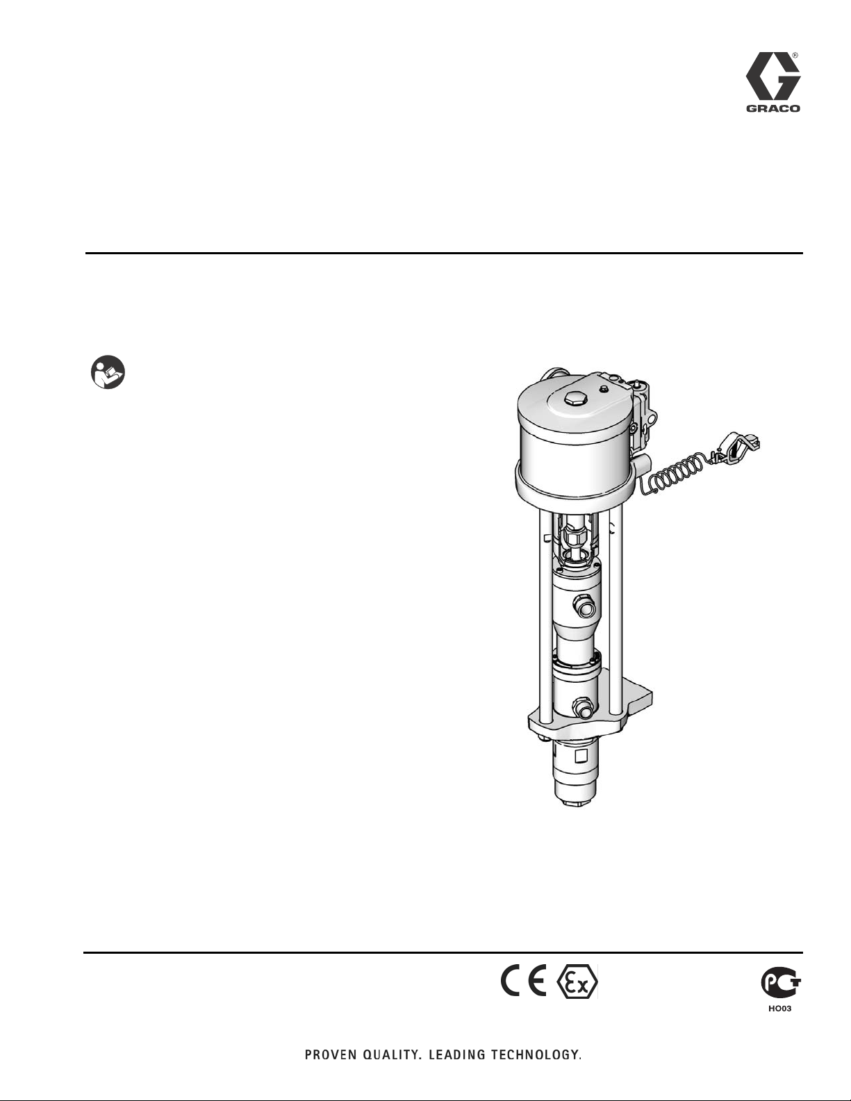
Merkur
Bellows
312795E
Pump Assembly
For pumping isocyanates, UV coatings, and other moisture-sensitive materials. For
professional use only.
Important Safety Instructions
Read all warnings and instructions in this
manual. Save these instructions.
See page 7 for model information, including maximum
working pressure.
EN
ti15361a
II 2 G c IIB T3 (200°C)

Related Manuals
Contents
Related Manuals . . . . . . . . . . . . . . . . . . . . . . . . . . . 2
Warnings . . . . . . . . . . . . . . . . . . . . . . . . . . . . . . . . . 3
Important Two-Component Material Information . 5
Isocyanate Conditions . . . . . . . . . . . . . . . . . . . . . 5
Material Self-ignition . . . . . . . . . . . . . . . . . . . . . . 5
Keep Components A and B Separate . . . . . . . . . 5
Moisture Sensitivity of Isocyanates . . . . . . . . . . . 5
Changing Materials . . . . . . . . . . . . . . . . . . . . . . . 5
Models . . . . . . . . . . . . . . . . . . . . . . . . . . . . . . . . . . . 6
Pump Data . . . . . . . . . . . . . . . . . . . . . . . . . . . . . . . . 7
Component Identification . . . . . . . . . . . . . . . . . . . . 8
Installation . . . . . . . . . . . . . . . . . . . . . . . . . . . . . . . 10
General Information . . . . . . . . . . . . . . . . . . . . . 10
Prepare the Operator . . . . . . . . . . . . . . . . . . . . 10
Prepare the Site . . . . . . . . . . . . . . . . . . . . . . . . 11
Grounding . . . . . . . . . . . . . . . . . . . . . . . . . . . . . 12
Mount the Pump . . . . . . . . . . . . . . . . . . . . . . . . 12
Air and Fluid Hoses . . . . . . . . . . . . . . . . . . . . . . 12
Accessories . . . . . . . . . . . . . . . . . . . . . . . . . . . . 13
Operation . . . . . . . . . . . . . . . . . . . . . . . . . . . . . . . . 14
Pressure Relief Procedure . . . . . . . . . . . . . . . . 14
Flush the Pump Before First Use . . . . . . . . . . . 14
Trigger Lock . . . . . . . . . . . . . . . . . . . . . . . . . . . . 14
Prime and Adjust the Pump . . . . . . . . . . . . . . . 15
Shutdown and Care of the Pump . . . . . . . . . . . 15
Maintenance . . . . . . . . . . . . . . . . . . . . . . . . . . . . . . 16
Preventive Maintenance Schedule . . . . . . . . . . 16
Tighten Threaded Connections . . . . . . . . . . . . . 16
Flushing . . . . . . . . . . . . . . . . . . . . . . . . . . . . . . . 16
Troubleshooting . . . . . . . . . . . . . . . . . . . . . . . . . . . 17
Repair . . . . . . . . . . . . . . . . . . . . . . . . . . . . . . . . . . . 18
General Information . . . . . . . . . . . . . . . . . . . . . . 18
Preparation . . . . . . . . . . . . . . . . . . . . . . . . . . . . 18
Disconnect the Pump . . . . . . . . . . . . . . . . . . . . 18
Reconnect the Pump . . . . . . . . . . . . . . . . . . . . . 20
Parts . . . . . . . . . . . . . . . . . . . . . . . . . . . . . . . . . . . . 22
Parts That Vary by Model . . . . . . . . . . . . . . . . . 23
Repair Kits . . . . . . . . . . . . . . . . . . . . . . . . . . . . . . . 24
Wall Mounting Kits . . . . . . . . . . . . . . . . . . . . . . . 24
Cart Mounting Kit 24E879 . . . . . . . . . . . . . . . . . 24
Accessories . . . . . . . . . . . . . . . . . . . . . . . . . . . . 24
Performance Charts . . . . . . . . . . . . . . . . . . . . . . . . 26
Pump Dimensions . . . . . . . . . . . . . . . . . . . . . . . . . 30
Wall Bracket Mounting Dimensions . . . . . . . . . . . 31
Technical Data . . . . . . . . . . . . . . . . . . . . . . . . . . . . 31
Graco Standard Warranty . . . . . . . . . . . . . . . . . . . 32
Related Manuals
Manual Description
312793 Merkur Bellows Displacement Pump
312796
312799
312798 Merkur Electrostatic Spray Packages
2 312795E
™
NXT
Air Motor
Merkur Bellows Spray Packages, AA
and Airless

Warnings
Warnings
The following warnings are for the setup, use, grounding, maintenance, and repair of this equipment. The exclamation point symbol alerts you to a general warning and the hazard symbols refer to procedure-specific risks. When
these symbols appear in the body of this manual, refer back to these Warnings. Product-specific hazard symbols and
warnings not covered in this section may appear throughout the body of this manual where applicable.
WARNING
WARNINGWARNINGWARNING
FIRE AND EXPLOSION HAZARD
Flammable fumes, such as solvent and paint fumes, in work area can ignite or explode. To help prevent
fire and explosion:
• Use equipment only in well ventilated area.
• Eliminate all ignition sources; such as pilot lights, cigarettes, portable electric lamps, and plastic drop
cloths (potential static arc).
• Keep work area free of debris, including solvent, rags and gasoline.
• Do not plug or unplug power cords, or turn power or light switches on or off when flammable fumes
are present.
• Ground all equipment in the work area. See Grounding instructions.
• Use only grounded hoses.
• Hold gun firmly to side of grounded pail when triggering into pail.
• If there is static sparking or you feel a shock, stop operation immediately. Do not use equipment
until you identify and correct the problem.
• Keep a working fire extinguisher in the work area.
Static charge may build up on plastic parts during cleaning and could discharge and ignite flammable
vapors. To help prevent fire and explosion:
• Clean plastic parts only in a well ventilated area.
• Do not clean with a dry cloth.
• Do not operate electrostatic guns in equipment work area.
SKIN INJECTION HAZARD
High-pressure fluid from gun, hose leaks, or ruptured components will pierce skin. This may look like just
a cut, but it is a serious injury that can result in amputation. Get immediate surgical treatment.
• Do not spray without tip guard and trigger guard installed.
• Engage trigger lock when not spraying.
• Do not point gun at anyone or at any part of the body.
• Do not put your hand over the spray tip.
• Do not stop or deflect leaks with your hand, body, glove, or rag.
• Follow the Pressure Relief Procedure when you stop spraying and before cleaning, checking, or ser-
vicing equipment.
• Tighten all fluid connections before operating the equipment.
• Check hoses and couplings daily. Replace worn or damaged parts immediately.
312795E 3
Warnings
WARNING
WARNINGWARNINGWARNING
EQUIPMENT MISUSE HAZARD
Misuse can cause death or serious injury.
• Do not operate the unit when fatigued or under the influence of drugs or alcohol.
• Do not exceed the maximum working pressure or temperature rating of the lowest rated system com-
ponent. See Technical Data in all equipment manuals.
• Use fluids and solvents that are compatible with equipment wetted parts. See Technical Data in all
equipment manuals. Read fluid and solvent manufacturer’s warnings. For complete information about
your material, request MSDS from distributor or retailer.
• Do not leave the work area while equipment is energized or under pressure. Turn off all equipment
and follow the Pressure Relief Procedure when equipment is not in use.
• Check equipment daily. Repair or replace worn or damaged parts immediately with genuine manufacturer’s replacement parts only.
• Do not alter or modify equipment.
• Use equipment only for its intended purpose. Call your distributor for information.
• Route hoses and cables away from traffic areas, sharp edges, moving parts, and hot surfaces.
• Do not kink or over bend hoses or use hoses to pull equipment.
• Keep children and animals away from work area.
• Comply with all applicable safety regulations.
MOVING PARTS HAZARD
Moving parts can pinch, cut or amputate fingers and other body parts.
• Keep clear of moving parts.
• Do not operate equipment with protective guards or covers removed.
• Pressurized equipment can start without warning. Before checking, moving, or servicing equipment,
follow the Pressure Relief Procedure and disconnect all power sources.
SUCTION HAZARD
Powerful suction could cause serious injury.
• Never place hands near the pump fluid inlet when pump is operating or pressurized.
TOXIC FLUID OR FUMES HAZARD
Toxic fluids or fumes can cause serious injury or death if splashed in the eyes or on skin, inhaled, or swallowed.
• Read MSDSs to know the specific hazards of the fluids you are using.
• Store hazardous fluid in approved containers, and dispose of it according to applicable guidelines.
• Always wear chemically impermeable gloves when spraying, dispensing, or cleaning equipment.
PERSONAL PROTECTIVE EQUIPMENT
You must wear appropriate protective equipment when operating, servicing, or when in the operating area
of the equipment to help protect you from serious injury, including eye injury, hearing loss, inhalation of
toxic fumes, and burns. This equipment includes but is not limited to:
• Protective eyewear, and hearing protection.
• Respirators, protective clothing, and gloves as recommended by the fluid and solvent manufacturer.
4 312795E
Important Two-Component Material Information
Important Two-Component Material Information
Isocyanate Conditions
Spraying or dispensing materials containing isocyanates creates potentially harmful mists, vapors, and
atomized particulates.
Read material manufacturer’s warnings and material
MSDS to know specific hazards and precautions
related to isocyanates.
Prevent inhalation of isocyanate mists, vapors, and
atomized particulates by providing sufficient ventilation in the work area. If sufficient ventilation is not
available, a supplied-air respirator is required for
everyone in the work area.
To prevent contact with isocyanates, appropriate personal protective equipment, including chemically
impermeable gloves, boots, aprons, and goggles, is
also required for everyone in the work area.
Material Self-ignition
Some materials may become self-igniting if applied
too thickly. Read material manufacturer’s warnings
and material MSDS.
Moisture Sensitivity of Isocyanates
Isocyanates (ISO) are catalysts used in two component
coatings. ISO will react with moisture (such as humidity)
to form small, hard, abrasive crystals, which become
suspended in the fluid. Eventually a film will form on the
surface and the ISO will begin to gel, increasing in viscosity. If used, this partially cured ISO will reduce performance and the life of all wetted parts.
NOTE: The amount of film formation and rate of crystallization varies depending on the blend of ISO, the
humidity, and the temperature.
To prevent exposing ISO to moisture:
• Always use a sealed container with a desiccant
dryer in the vent, or a nitrogen atmosphere. Never
store ISO in an open container.
• Use moisture-proof hoses specifically designed for
ISO, such as those supplied with your system.
• Never use reclaimed solvents, which may contain
moisture. Always keep solvent containers closed
when not in use.
• Never use solvent on one side if it has been contaminated from the other side.
• Always lubricate threaded parts with ISO pump oil
or grease when reassembling.
Changing Materials
Keep Components A and B Separate
Cross-contamination can result in cured material in
fluid lines which could cause serious injury or damage equipment. To prevent cross-contamination of
the equipment’s wetted parts, never interchange
component A (isocyanate) and component B (resin)
parts.
312795E 5
• When changing materials, flush the equipment multiple times to ensure it is thoroughly clean.
• Always clean the fluid inlet strainers after flushing.
• Check with your material manufacturer for chemical
compatibility.
• Most materials use ISO on the A side, but some use
ISO on the B side.
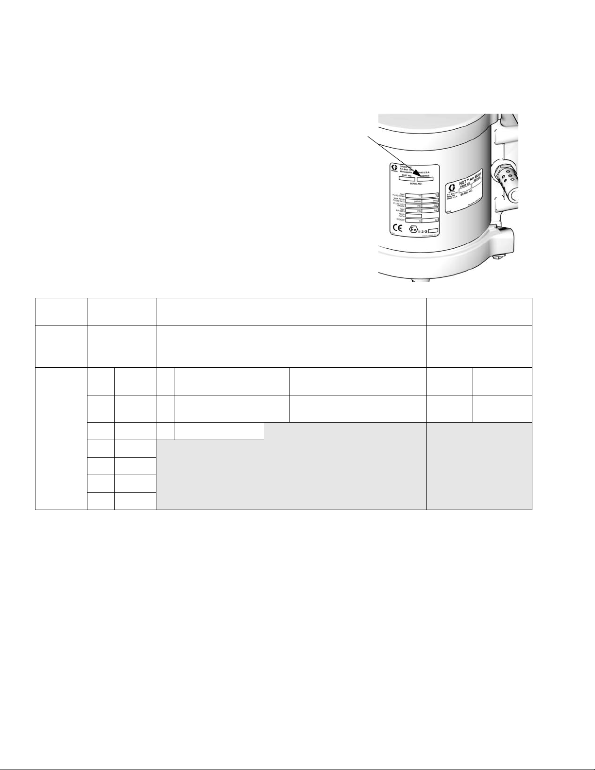
Models
Models
Check your pump’s identification marking (ID) for the 6-digit part number.
Use the following matrix to define the construction of your pump, based on
the six digits. For example, pump Part No. B05FA0 represents a 5 to 1
ratio, 150 cc pump, with no DataTrak, a low noise exhaust, and v-packings
To order replacement parts, see Parts section starting on page 22. The
digits in the matrix do not correspond to the reference numbers in the
Parts drawings and lists.
B05 F A 0
ID
ti12922a
Second and
First
Digit
B
(Bellows
style)
* Cycle refers to combination of one upstroke and one downstroke.
Third Digit
(Ratio)
05
12
15
23
24
25
35
5:1
12:1
15:1
23:1
24:1
25:1
35:1
Fourth Digit
(Displacement Pump
Volume Per Cycle)
B
D
F
50 cc
100 cc
150 cc
A
B
(Smarts/Exhaust)
DataTrak Compatible,
Fifth Digit
No DataTrak,
low noise exhaust
low noise exhaust
Sixth Digit
(Packings)
0
V-packings
1
U-cup
packings
6 312795E

Pump Data
Pump Data
Air
Model, Series
B05FA0, Series A M04LN0
B05FB0, Series A M04LT0
B05FA1, Series A M04LN0
B05FB1, Series A M04LT0
B12DA0, Series A M07LN0
B12DB0, Series A M07LT0
B12DA1, Series A M07LN0
B12DB1, Series A M07LT0
B15BA0, Series A M04LN0
B15BB0, Series A M04LT0
B15BA1, Series A M04LN0
B15BB1, Series A M04LT0
B15FA0, Series A M12LN0
B15FB0, Series A M12LT0
B15FA1, Series A M12LN0
B15FB1, Series A
B23DA0, Series A M12LN0
B23DB0, Series A M12LT0
B23DA1, Series A M12LN0
B23DB1, Series A
B24FA0, Series A M18LN0
B24FB0, Series A M18LT0
B24FA1, Series A M18LN0
B24FB1, Series A M18LT0
B25BA0, Series A M07LN0
B25BB0, Series A M07LT0
B25BA1, Series A M07LN0
B25BB1, Series A M07LT0
B35DA0, Series A M18LN0
B35DB0, Series A M18LT0
B35DA1, Series A M18LN0
B35DB1, Series A M18LT0
Motor
M12LTO
M12LTO
Displacement
Pump
LB150A
LB150B
LB100A
LB100B
LB050A
LB050B
LB150A
LB150B
LB100A
LB100B
LB150A
LB150B
LB050A
LB050B
LB100A
LB100B
Maximum Fluid
Working Pressure
psi (MPa, bar)
500 (3.4, 34) 2.4 (9.0) 1 in. npt 3/4 in. npt 1/4 in. npt
1200 (8.3, 83) 1.6 (6.0) 3/4 in. npt 3/8 in. npt 1/2 in. npt
1500 (10.3, 103) 0.8 (3.0) 3/4 in. npt 3/8 in. npt 1/4 in. npt
1500 (10.3, 103) 2.4 (9.0) 1 in. npt 3/4 in. npt 1/2 in. npt
2300 (15.9, 159) 1.6 (6.0) 3/4 in. npt 3/8 in. npt 1/2 in. npt
2400 (16.5, 165) 2.4 (9.0) 1 in. npt 3/4 in. npt 1/2 in. npt
2500 (17.2, 172) 0.8 (3.0) 3/4 in. npt 3/8 in. npt 1/2 in. npt
3500 (24.1, 241) 1.6 (6.0) 3/4 in. npt 3/8 in. npt 1/2 in. npt
Flow Rate
at 60 cpm
gpm (lpm) Fluid Inlet
Fluid
Outlet Air Inlet
312795E 7
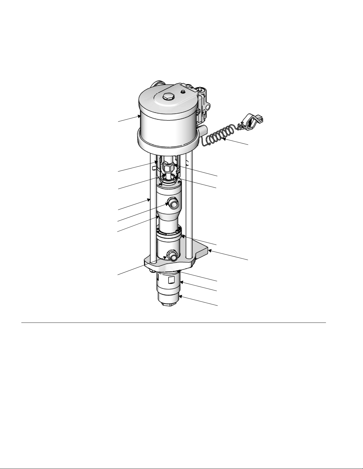
Component Identification
Component Identification
A
H
FIG. 1. Component Identification
Key:
A Air Motor
B Coupler Shield
C Connecting Rod
D Tie Rod
E Fluid Inlet
F Bellows Chamber
G Fluid Outlet
B
C
J
K
D
E
F
L
M
G
N
P
R
H Ground Wire
J Coupling Nut
K Coupling Collar
L Packing Nut
M Pump Adapter
NJam Nut
P Cylinder
RFoot Cap
ti15361a
8 312795E

Component Identification
312795E 9
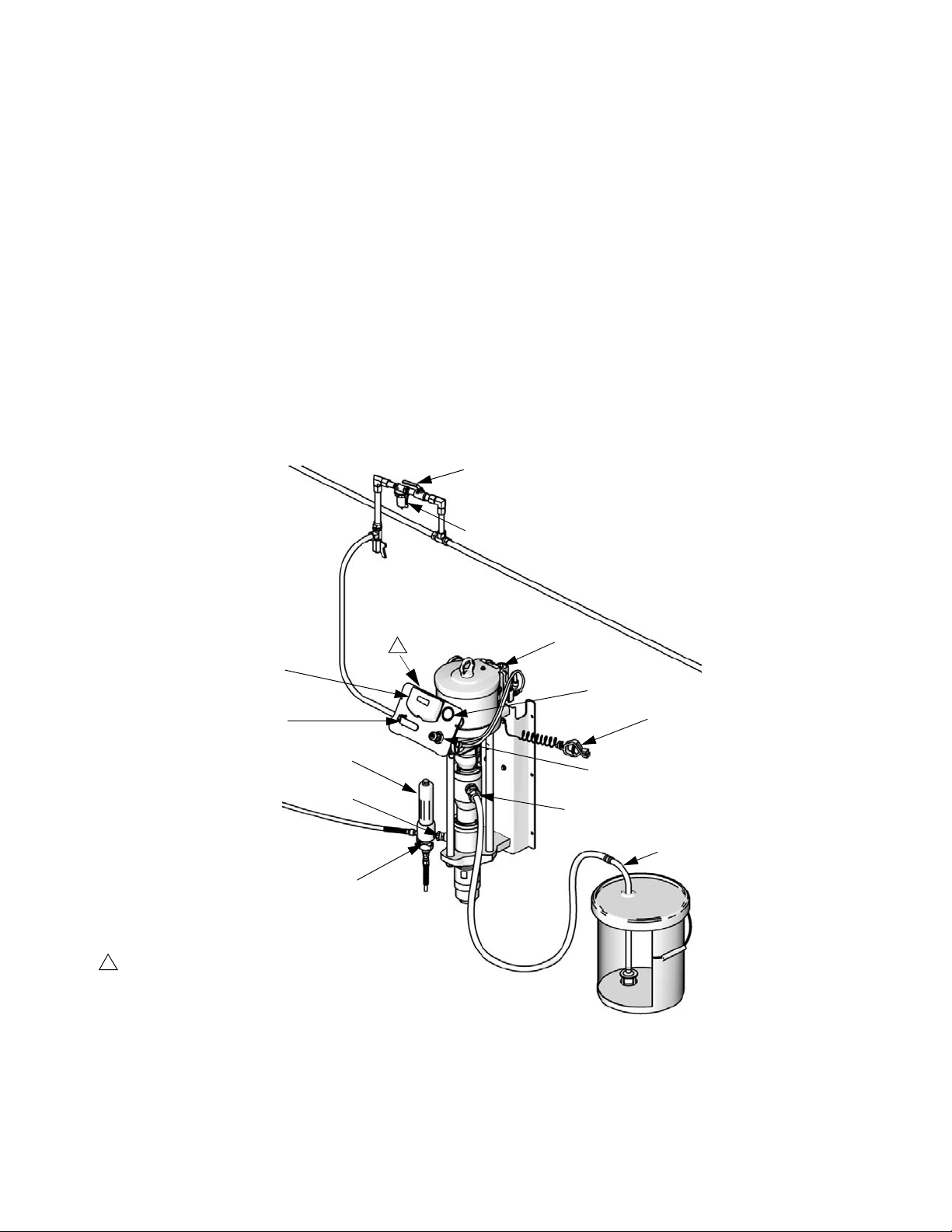
Installation
Installation
General Information
NOTE: Reference numbers and letters in parentheses in
the text refer to the callouts in the figures and the parts
drawing.
F
IG. 2 and FIG. 3 are only guides for selecting and
installing system components and accessories. Contact
your Graco distributor for assistance in designing a system to suit your particular needs.
NOTE: Always use Genuine Graco Parts and Accessories, available from your Graco distributor. If you supply
your own accessories, be sure they are adequately
sized and pressure-rated for your system.
1
F
E
P
R
Prepare the Operator
All persons who operate the equipment must be trained
in the operation of all system components as well as the
proper handling of all fluids. All operators must thoroughly read all instruction manuals, tags, and labels
before operating the equipment.
A
B
J
G
S
H
T
U
V
1
Use alternate mounting holes (on bracket, not
visible) to mount air controls vertically.
ti15363a
FIG. 2: Typical Wall-Mount Installation
10 312795E
 Loading...