

MERKLE TIG 254 AC/DC, TIG 300 DC, TIG 240 DC, TIG 180 DC, TIG 171 AC/DC Operation Manual
...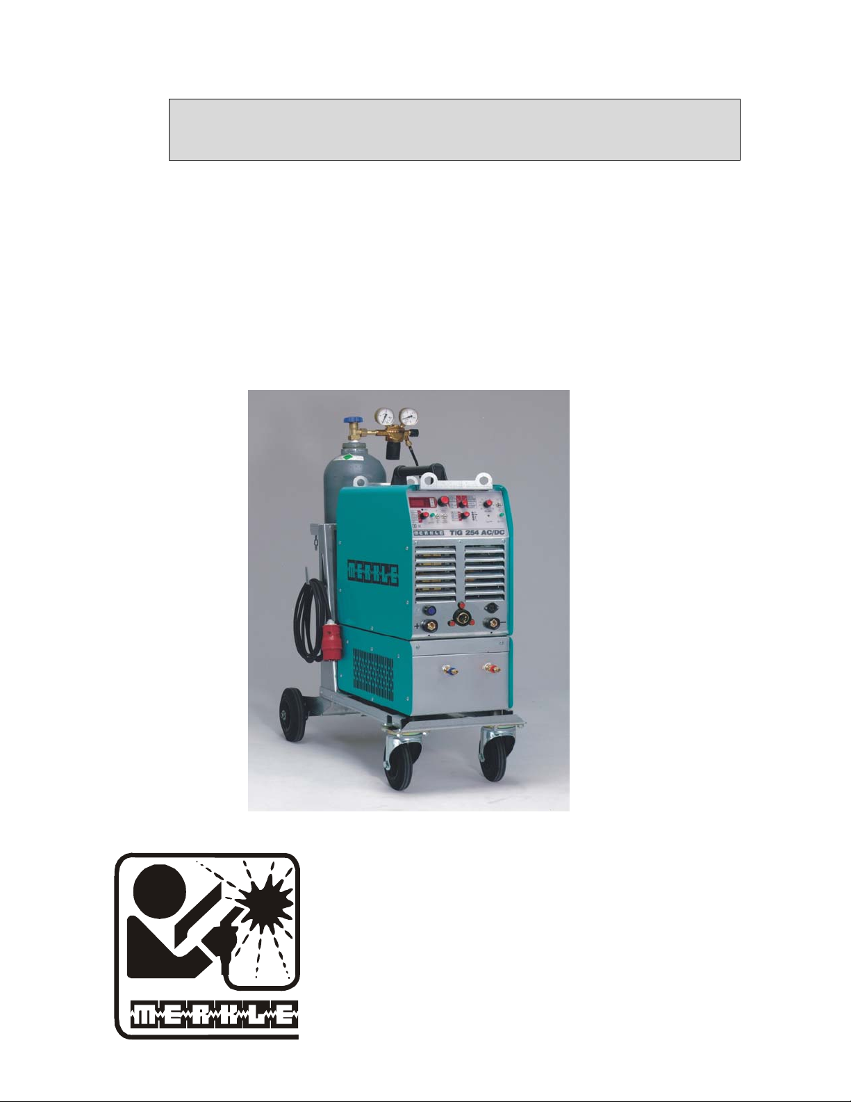
Operation Manual
TIG Welding Units
Model TIG 254 AC / DC
with MERKLE TCG connector
MERKLE
Schweissanlagen-Technik GmbH
Industriestrasse 3
D-89359 Koetz,
Germany
Tel.: ++49-8221-915-0
Fax: ++49-8221-915-40
www.merkle.de

.

Content page
1 Security indications before introduction 3
2 Accident prevention regulations 3
2.1 Safety instructions 3
3 Duty cycle 5
4 Instructions to avoid interferences due to electromagnetic influences EMC 5
5 Technical Data: 7
5.1 TIG AC/DC Welding Unit, model TIG 254 AC/DC: 7
5.2 Accessories, water cooling unit, model WK 230 9
6 Start Up 9
6.1 Installation of the Machine 9
6.2 Main Supply 10
6.3 Operation with the unit connected to a generator 10
6.4 Torch connect 10
6.5 Earth Lead (Work Cable) 10
6.6 Electrode holder 10
6.7 Transport 10
7 TIG-Welding Unit TIG 254 AC/DC 11
8 Operation of the Unit 12
9 TIG welding 16
9.1 preparing-values at DC welding 16
9.2 preparing-values at AC- welding 16
10 PARAMETERS 17
11 MMA stick electrode –welding 18
10.4.1 Standard value for the metal arc welding 18
12 Cleaning 19
13 Maintenance and Accident Prevention 19
1

14 Trouble Shooting 19
15 TIG hand welding torch - and spare parts 21
15.1 TIG Hand Welding Torch, Model TH 250 G, gas cooled 21
16 Spare parts and wiring diagram 27
16.1 Spare part list TIG 254 AC/DC 27
16.2 Wiring diagram TIG 254 AC/DC 28
16.3 Spare part list WK 230/300 33
16.4 Wiring diagram WK 230/300 33
17 EU-Conformity Attestation TIG 254 AC/DC 35
18 EU-Conformity Attestation WK 230/300 36
2

1 Security indications before introduction
The unit device is built after the recognized standards. Safe works are nevertheless only possible
if you read the operating instructions and the safety regulations contained in it entirely and obey
strictly. Install yourselves by trained staff of our establishments or appointed dealers.
2 Accident prevention regulations
The following accident prevention regulation is applied for welding unit,
model TIG 254 AC-DC
BGV D1 (earlier VBG 15) * Welding, cutting and allied processes.
A copy of this regulation should be readily accessible in every welding shop. The stipulations of
this regulation are to be observed in the interests of safe and correct welding operation.
* Available from the trade association responsible or
Carl Heymanns-Verlag, Luxemburger Strasse 449, 50939 Cologne.
2.1 Safety instructions
This unit is manufactured according to the requirements and stipulations of EN 60974.1 / VDE
0544 part 1. BGV D1 (earlier VBG 15) of the trade association for precision engineering and
electrical engineering are as well valid.
1) In case of an accident, the welding unit must be disconnected from the mains
immediately.
2) If electrical contact voltages arise, switch off the unit immediately, disconnect it from the
mains and proceed to inspection by a qualified electrician or by our Service Department.
3) Before opening the unit, disconnect it from the mains supply.
4) Repair work may only be carried out by a skilled electrician or by our Service
Department.
5) Before the unit is put to operation, check it visually, as well as the torch and all cables and
connectors regarding possible external damages.
6) Personal protective equipment in accordance with DIN EN 175, DIN EN 379 and
DIN EN 169.
During the work, the welder’s body must be completely protected against radiation and
burns by means of protective clothing and face protection. Long gloves, aprons and
welding shields with welding filters conforming to DIN EN 470-1 and BGR 189
must be worn.
Synthetic clothing are excluded. Shoes must be closed, not opened (due to spatters). If
necessary, protective headwear must be worn (e.g. for overhead welding). If cover glasses
are used, these must be in accordance with the norms specified above.
As additional protection for the eyes against UV radiation, safety goggles with side
shields and corresponding face protection in accordance with BGR 192 and BGI 553 must
be worn. Accident prevention regulation BGV D1 § 27 stipulates that it is the
responsibility of the employer to provide suitable personal protective equipment, while
§ 28 stipulates that it is the responsibility of the insured to wear suitable clothing.
3

7) Protection when welding under increased electrical risks
Welding rectifiers and welding power sources which can optionally be used for either
direct or alternating current must be marked "S" in accordance with EN 60974-1 and BGI
534.
Use insulating materials to protect you against contact with electrically conductive parts
and damp floors. Wear dry, undamaged work clothing, long gloves and footwear with
rubber soles. Ventilate rooms, install extraction systems if required, and wear respiratory
protective equipment if necessary (see Procedural instructions BGV D1 § 27 and BGI
533, Section 5).
8) In order to prevent stray currents and the effects thereof (e.g. destruction of electrical
protective ground conductors), the welding return cable (workpiece cable) must be
connected directly to the workpiece to be welded or to the table (e.g. welding table, gridtype welding table, workbench) supporting the workpiece (see BGV D1 § 20). When
installing the ground connection, assure that there is a good electrical contact (remove rust,
paint, etc.).
9) During welding pauses, the welding torch is to be laid down on an insulated surface or
hung up in such a way that it is not in contact with the workpiece and its support
connected to the welding power source (see § 20 BGV D1).
In the case of longer work pauses, the welding unit must be switched off and the gas
cylinder valve must be closed.
10) The shielding gas cylinder must always be protected against tumbling downing using a
safety chain.
11) Under no circumstances the unit may be put into operation while it is opened
(e.g. for repair work). Apart from the safety regulations, sufficient cooling of the
electrical components provided by the fan cannot be guaranteed.
12) In accordance with BGV D1 § 5, people in the vicinity of the arc must also be informed of
the hazards and protected against them. Safety partitions (“welding safety curtains”) must
be erected in accordance with DIN EN 1598.
14) N
o welding work may be carried out on containers in which gases, fuels, mineral oils or
similar substances have been stored even if they have been empty for a long time
(risk of explosion). See § 31 of accident prevention regulation BGV D1.
15) Welds which will be subjected to high loads and which need to meet specific safety
requirements may only be carried out by specially trained and qualified welders.
15) Never bring the torch close to your face.
16) In areas at particularly high risk of fire, the welder must obtain a welding permit and have
this on his person throughout the duration of the welding work. On completion of
welding, a fire-guard must be delegated to ensure fire protection.
17) Ventilation measures must be applied in accordance with BGI 553, Section 9.
4

18) The hazard to eyesight must be indicated by means of a sign at the work site
"CAUTION! Do not look into the arc!".
3 Duty cycle
The duty cylce measurings have been carried out in accordance with
EN 60974-1 / VDE 0544 part 1 (10 min working period).
60% duty cycle means:
After a 6 min. welding period a 4 min welding pause must be respected. The electrical
components are thermally protected against overheating.
4 Instructions to avoid interferences due to electromagnetic influences EMC
The welding unit has been manufactured in accordance with the requirements of guideline
EN 60974-10 / VDE 0544 part 10 regarding electromagnetic compatibility. It is nonetheless the
responsibility of the user to ensure that the welding equipment is installed and operated in
accordance with the manufacturer’s instructions. If electromagnetic interference is detected, it is
the responsibility of the user of the welding equipment to find a solution with the technical
assistance of the manufacturer. In some cases, it may be sufficient simply to ground the welding
current circuit. In other cases, it may be necessary to build a complete shield for the welding
power source and workpiece using the input filters. In all cases, electromagnetic interference
must be reduced to avoid any possible malfunctions.
Note:
For safety reasons, the welding current circuit may or may not be grounded. No
modifications may be made to the grounding without the approval of an expert who is able to
determine whether the changes might increase the risk of accidents, e.g. by allowing parallel
welding current return paths which could destroy the ground conductors of other equipment.
Further instructions are contained in TEC 974-XX "Arc welding equipment – installation and
use".
a) Evaluation of the installation site
Before installing the welding equipment, the user must evaluate potential electromagnetic
problems in the vicinity. The following must be taken into consideration:
Other power cables, control cables, signal and telecommunication cables above, below
and next to the welding equipment
Radio and television transmitters and receivers
Computers and other control devices
The health of people in the vicinity, e.g. use of heart pacemaker and hearing aids
Calibration and measuring equipment
Interference immunity of other devices in the vicinity. The user must ensure the
electromagnetic compatibility of other devices used in the vicinity. This may require
additional safety measures.
b) Procedures to reduce emitted interference
1) Mains supply
Welding equipment is to be connected to the mains in compliance with the
recommendations of the manufacturer. If interference occurs, it may be necessary to take
additional precautions, e.g. filters for the mains connection. Make sure that the power
5

cable of welding equipment is installed in a fixed position shielded by means of a metal
conduit or similar. The entire length of the shield must be electrically connected. The
shield must be connected to the welding power source in the way to obtain a good
electrical contact between the metal conduit and the housing of the welding unit.
2) Maintenance of the welding equipment
Welding equipment must be maintained regularly in accordance with the
recommendations of the manufacturer. All access and service doors and covers must be
closed and fastened securely when the welding equipment is in operation. No
modifications whatsoever may be made to welding equipment with the exception of
modifications and adjustments specified in the manufacturer’s operating instructions.
3) Welding cables
Welding cables should be kept as short as possible and routed close together on or near
the floor.
4) Equipotential bonding
It is advisable to interconnect all metallic parts in and next to the welding equipment.
Metallic parts connected to the workpiece can, however, increase the risk of the welder
receiving an electric shock by touching these metallic parts and the electrode
simultaneously. The welder must be electrically insulated against all these connected
metallic parts.
5) Grounding the workpiece
If the workpiece is not connected to the ground for electrical safety reasons, or due to the
size and position of the workpiece, e.g. steel structure or outer wall of a ship, grounding
the workpiece may in some cases, but not all, reduce emitted interference. It must be
ensured that grounding the workpiece will not increase the risk of accidents for the user
and cannot cause the destruction of other electrical equipment. If necessary, the grounding
of the workpiece must be carried out by means of a direct connection to the workpiece. In
countries where a direct connection is prohibited, the connection must be made by means
of suitable reactors, selected in accordance with national regulations.
6) Shielding
Selective shielding of other cables and devices in the vicinity can reduce interference
problems. For special applications, it may be worth considering shielding the entire
welding system.
6

5 Technical Data:
5.1 TIG AC/DC Welding Unit, model TIG 254 AC/DC:
Primary:
Supply: 3 x 400 V
Frequency: 50-60 Hz
cos phi: 0.95
TIG operation:
Open circuit voltage: 70 V
Welding voltage: 10-20 V
Welding current: 5-250 A
Duty cycle 45 %: 250 A (10 min.)
Duty cycle 60 %: 230 A (10 min.)
Duty cycle 100 %: 210 A (40°C)
Prim. cont. power: 5.5 kVA
Prim. cont. current: 8 A
Prim. max. current: 11 A
MMA/stick electrode operation:
Stick electrodes: 1.5-6 mm
Open circuit voltage: 70 V
Welding voltage: 20-30 V
Welding current: 5-250 A
Duty cycle 40 %: 250 A (10 min.)
Duty cycle 60 %: 220 A (10 min.)
Duty cycle 100 %: 200 A (40°C)
Prim. cont. power: 9.7 kVA
Prim. cont. current: 14 A
Prim. max. current: 16 A
Protection class: IP 23 (with filter)
Insulation class: H
Colling: AF
Main switch: 3-phase
Operation modes: 2-stroke, 4-stroke,
4-stroke with 2 currents,
4-stroke with current program,
MMA/stick electrode welding
Selector: current 1, current 2,
time 1, time 2,
down slope, gas post flow time,
AC freuqency,
parameter programming
Setting: continuous at rotary switch
7

Energy control: at the unit, at the torch,
hand remote control, foot pedal
Switch: HF/lift arc
Switch: pulsation ON/OFF
Switch: AC mode/DC mode
Switch: test protection device
Button: gas check with hold function
and timer, parameter selection
Digital display: for current, time and
frequency, with pre-display
and hold function
Current 2: 10-250 % of current 1
Pulsation slow: 0.1-2.5 s
Pulsation fast: 50-800 Hz
Pulse shape: "hard" / "soft"
Down slope time: 0-15 s
Up slope time: 0-2 s
Gas pre-flow time: 0-3 s
Gas post-flow time: 3-25 s
Positv ignition impulse: 0-100 ms
AC balance: ± 90 %
AC frequency: 50-200 Hz
AC curve shape: square or noise reduced
Hotstart time: 0-1.5 s
Hotstart current: 5-250 A
Arc force: max. 250 A
LED green: mains ON,
LED green: welding ON,
LED green: Urms<48 V,
LED yellow: temperature protection,
LED red: failure
Socket: remote control
Power source: IGBT inverter
Ignition: HF ignition generator
Norm: EN 60974-1 "S" / CE
Torch connection: Merkle TCG connector
and 5-pole plug
Torch cooling: gas
option: water
Socket 50 mm²: earth lead
Socket 50 mm²: electrode welding cable
Mains supply cable: 4 x 1.5 mm², 5 m long
with plug 3 x 400 V/ 16 A
Gas hose: 2 m long
8

Connection for water
cooling unit: socket 6-pole (option)
for mains supply and
water pressure control
Handle: on top of the machine
Weight: 39 kg
Dimensions L x W x H: 600 x 300 x 565 mm
Standard accessories:
Earth lead 35 mm², 4 m long 022.1.0401
with plug and earth clamp
Regulator argon/CO2 107.018
standard version
5.2 Accessories, water cooling unit, model WK 230
Technical data:
Power supply: 1 x 400 V / 230 V
Frequency: 50 Hz (60 Hz)
Mains current: 1 A / 1.6 A
Water pump: high efficient pump 230 V
Water prussure: 3.5 bar
Water capacity: 3 l
Transformer: 400 / 230 V
Water pressure switch: integrated
Functions: automatic switch of fan
and water pump
Electr. connection: cable with 6-pole plug
water connection: 2 quick couplings
Weight: 18 kg
Dimensions L x W x H: 530 x 230 x 215 mm
6 Start Up
6.1 Installation of the Machine
Place the machine at least 0.80 m from a wall etc. to guarantee the cooling air can go
through the unit. The room temperature should not exceed 40°C.
The room were the unit is placed should have a low degree of humidity
(max. 50 % at 40°C, max. 90 % at 20° C).
The unit has passed the quality control in accordance with IP 23.
The air in the surroundings must be free from extreme quantities of dust, free from acides and
corrosive gases etc. Otherwise use air filters.
9

6.2 Main Supply
The main supply must be connected by a trained person. The main supply voltage is displayed on
the front or rear panel of the machine. A connection to ground (GND) must be done.
6.3 Operation with the unit connected to a generator
Consider the following comments:
The power of the generator must be at least 10% higher than the power of the welding unit.
The generator´s outcoming voltage must be stabilized in the no load voltage mode as well.
Due to possible peaks of the generator when switching ON, the welding unit should be
switched ON afterwards.
6.4 Torch connect
To plug into minus socket (Gas current clutch) torch connection gas current couplers of the
torch and to turn through right solid attract so that protective gas is sealed.
CAUTION: Employing Merkle TIG- torch only originally !
Otherwise assurance claim goes out
6.5 Earth Lead (Work Cable)
The earth lead must have an excellent ground. The clamp should be attached to a clean,
paint and rust free area on the work piece or on the welding table.
6.6 Electrode holder
Only use electrode holders with a proper insulation and a good contact with the electrode.
6.7 Transport
The plant without larger expenditure can be advanced by their low weight and by the
mounted handle.
The gas bottle must not be attached due to the small device emphasis to the plant.
10

7 TIG-Welding Unit TIG 254 AC/DC
The welding unit TIG 254 AC/DC is based on inverter technique and
are suitable for TIG-welding in AC, DC and for MMA/stick electrode welding. Continuous
setting of the welding current is up to 250 A.
Thanks to their portable, lightweight and compact design, they save space in the workshop and
it are particulary suitable for use at changing locations.
The units can be characterized by numerous features:
• inverter power source with continuous setting of the current 5 -250 A
• low weight: 39 kg only
• 2-stroke, 4-stroke Operation
• two welding currents separately adjustable at the torch
• high frequency (HF) and Lift-arc ignition
• continuous setting of the down slope
• socket for remote control
• gas post-flow adjustable
• digital read out with pre-display and hold-function
• TIG pulsation as a Standard
• Option: water cooling unit WK 230
• stick electrode operation:
1. Arc force:
increasing of the welding current in order
to avoid adherence of the electrode.
2. Hotstart function:
increasing of the start current to
assure a safe ignition.
3. Anti stick function:
In case of adherence of the electrode, the current
is switched off immediately. Reignition after separation
only is possible with a short retardation.
Option: Water cooling unit WK 230
Easy mounting and dismounting of the water cooling unit WK 230 in a few seconds with
electrical pluggable connection.
Generator and water cooling System then form one light and compact unit easy to transport.
Different applications are possible p. ex.:
• welding with a water cooled torch in the workshop,
• using a gas cooled torch on the building site.
11

Front panel TIG 254 AC/DC
8 Operation of the Unit
1: selector Operation mode
a) TIG-DC /AC-DC weldinq: 2-stroke
1st stroke: after pressing the torch switch the current is switch on
2nd stroke: after releasing the torch switch the current is
decreased to the "final current" according to the
"down slope time" and switched off. The "gas post-
flow time" Starts.
12

b) TIG-DC /AC-DC welding: 4-stroke
1st stroke: after pressing the torch switch and igintion ofthe
arc the "inital current" is activated
2nd stroke: after releasing the torch switch current is increased
to the selected value of "current 1"
3rd stroke: after pressing the torch switch the "down-slope" is
activated. The welding current is reduced to the
"final current" which is active until step 4
4th stroke: the torch switch is released: the "down-slope" is
stopped and the welding is switch off or the "final
current" is switch off. The "gas post-flow time" starts.
If the torch is equipped with two switches, the "current 2" can be activated by pressing the second
switch during the welding process.
c) TIG-DC /AC-DC welding: 4-stroke with current I1 and I2
This Operation mode is similar to the Standard 4-stroke operation. By using a torch with
one torch switch, the welding current is switched from "current 1" to "current 2" and v. v.
by a short touch of the torch switch (less than 0.5 s). If the torch switch is press down
longer than 0.5 s the 3rd stroke is activated ("down slope")
d) TIG-DC /AC-DC welding: 4-stroke with current Programm
This Operation is similar to the 4-stroke Operation. In the 3rd stroke the
current is reduced with the down slope time. If the torch switch is released
the current will return to the pre-selected value 1. By pressing the torch switch
less than 0.5 s the current is switched off immediately.
e) Stick electrode Operation
2: Selector current control
a) control at the weldinq unit
The welding current is adjusted by turning the rotary switch (4) while selector (3)
is in position current I1. The value is displayed on the display (5).
b) control at the var. resistor at the torch
The maximum welding current is adjusted by turning the rotary switch (4) while
selector (3) is in position current I1. The welding current pre-selected by the var. resistor
at the torch is displayed in display (5).
c) control at the hand remote control
This function is identical to b). The electrical connection is made at the 10-pol.
remote control socket. The welding current pre-selected by the var. resistor at the
hand remote control is displayed in display (5).
13

d) control with a foot pedal
This function is identical to b). The electrical connection is made at the 10-pol.
remote control socket. The foot pedal is only working in TIG Operation mode.
3: Selector for rotary switch (4)
Dependend on the position of selector (1) the following values are displayed at
the digital read-out (5):
The LEDs show the unit: A ,s or Hz.
In TIG welding Operation:
- current I1 (5A...250A)
Main welding current.
In DC mode and AC mode (arc shape hard [HAr]) the current 11 is not limited.
In AC mode (arc shape soft [SOF]) the current I1 is limited to 100 A if the AC
frequency is more than 100 Hz.
In AC mode (arc shape sinusodial [Sin]) the current I1 is limited to 225 A at a fixed
frequency of 50 Hz.
- current I2
The current I2 is displayed in A. When the current I1 is changed, the current I2
also changes but remains in the same relation to I1 {10...200).
The seconed welding current I2 can be activated by a torch with two switches, in
4-stroke Operation with two currents or in the pulsation mode. The second current
is only working without a hand or foot remote control.
In case of adherence of the electrode the current is automatically reduced to a
minimum value.
4: Rotary switch
For adjustment of the parameters seicted by selector (3)
5: Digital read out
6: LED green: Hold-function
After the welding process the last value of welding current is
displayed and the LED (6) is on.
7:LEDs
7.1: green: welding ON
welding voltage is at the Output
7.2: green: mains ON
mains switch is switched on.
7.3: yellow: Thermical protection
electronic is too hot. Wait for cooling down of the unit but do not switch it off
14

(fan cooling)
7.4: red: failure
is on when an electronic failure occurs.
8: Buttom GASTEST
a) The buttom is working in 4-stroke mode with a automatic switch off of the
gas after 60 s.
b) In position parameter of selector (3) this buttom is for programming of the
Parameters.
9: Switch HF/Lift-arc
HF ignition: The arc will be started by a high frequency ignition generator. The tungsten
electrode may not touch the work piece at the ignition process.
Lift Arc ignition: Lift arc ignition is need, when TIG welding is performed close to
sensitive electronic devices. Touch down the tungsten electrode to the work piece, press
down the torch trigger and lift the electrode. While the tungsten electrode touches the
work piece a minimum current is activated in order to prevent the electrode from sticking
to the work piece.
10: Switch AC/DC
Depended on work piece the AC (for aluminium) or DC (for mild steel,
stainless steel, copper) mode has to be selected.
Automatic storage of selected values
All values selected with the selector (3) and the rotary switch (4) (current I1, I2, time
t1, t2, etc.) are automatically stored after the welding process is finished. They will be
shown in the display again when the machine is switched off and on again.
11: Potentiometer AC Balance
In AC TIG mode the ratio between positive and nagative AC current can be adjusted at
the potentiometer Balance. The scale on front plate shows the positive and negative ratio
of the welding current. Adjustment to more negative balance will result in a better
penetration, adjustment to more positive balance will result in a better cleaning of the
weld pool but also result in less penetration and vv.
Automatic safty switch off
In TIG Operation the welding voltage is automatically switched off after 2 s, when no
welding current is achived.
ATTENTION:
In TIG mode the welding voltage is also applied to the stick electrode socket. Disconnect
stick electrode cable when welding in TIG mode.
15

9 TIG welding
9.1 preparing-values at DC welding
- standard values for the TIG manual welding in level position of special alloy steels, direct
current minus polarity kind of current of 0,6, - 6 mm material thickness
Materialthicknes in
mm
0,6
0,8
1,0
1,5
2,0
2,5
3,0
4,0
6,0
Weld
-form
I
I
I
I
I
I
I
I
I
Seamdistance
in mm
- 20-30 1 1,6 1,0 4 5
- 40 1 1,6 1,0 4 5
- 45 1 1,6 1,0 4 5
- 50 1 1,6 1,6 4-6 6
- 80-100 1 2,4 1,6 6-8 7
- 100-130 1 2,4 1,6 6-8 7
- 140 two sided 2,4 2,4 8 7
V-
shaping.
X-
shaping.
Midle
weldingcurrent
in A
180 1 2,4 3,2 8-10 10
220 2 2,4 3,2 8-10 10
Number
of layers
Welding-
rod
in mm
wolframelectrode
grey
in mm
Argon tip
Argon
welding gas
l/min.
9.2 preparing-values at AC- welding
standard values for the TIG manual welding in level position of aluminum, alternating current
kind of current of 1,0, - 6 mm material thickness
Materialthicknes in
mm
0,8
1,0
2,0
3,0
4,0
5,0
6,0
Weld
-form
I
I
I
I
V
V
V
Seamdistance
in mm
- 35 1 1,6 1,0 4 5
- 50 1 1,6 1,6 4 5
- 95 1 2,4 2,4 6-8 7
- 140 1 2,4 2,4 8 7
V 185 1 3,2 3,2 8-10 10
V-
shaping..
Xshaping..
Midle
weldingcurrent
in A
235 2 3,2 3,2 8-10 10
300 2 4,0 3,2 8-10 12
Number
of layers
Welding-
rod
in mm
Wolfram
electrode
red
in mm
Argon tip
For blunt seams on one side in normal and overhead-position are the current values around 5
to 10 %, to increase for throat and overlap joints around 10 %. The table values are valid for
fillet welds as before.
Argon
welding gas
l/min.
16

10 PARAMETERS
Set selector (3) to position 'PARAMETER'. Select one parameter by pressing the buttom
'GASTEST'. The selected parameter can be adjusted by the rotary switch (4).
The display (5) first shows the paramter's number (for example P1). Then the parameter's
name is shown [tGAS]. After a short time the value is displayed and can be adjusted by turning
the rotary switch.
The parameters are stored when you select any other postion than 'PARAMETER' at the
selector (3)
name on the display parameter
P1 [tGAS]
gas pre flow time
value/range
0-3s
delivery
setting
Os
your
setting
P2 [tUP]
P3 [IStArt]
P4 [lEnd]
P5 [PULS]
P6 [SPEEd]
P7 [tPLUS]
up slope time
initial current
final current
DC pulse shape
- hard
- soft
DC pulsation frequency
- slow(t1,t2:0.1-2.5s)
- fast (t1: 50 - 800 Hz)
(t2: 2-8 to 8-2
timepart I1-I2)
time of positive ignition pulse
in AC mode
0-2s
5 - 250 A
5 - 250 A
[HAr]
[SOF]
[LO]
[Hl]
0…100ms
0.1s
20 A
20 A
[SOF]
[LO]
50Hz
5-5
20ms
P8 [AC]
switching:
AC curve shape - hard
-soft
-sin (low noice
[HAr]
[SOF]
[SIn]
[HAr]
only 50 Hz)
With DC pulse shape set to 'hard' the currents I1 and I2 are switched without any slopes.
In position 'soft' the pulse edges are smoothed for a noise reduction.
In 'fast pulsation' only the 'hard' mode is working.
17

11 MMA stick electrode –welding
To the stick electrode -welding set the rotary switch (1) into the lowest position.
Caution:
Open-circuit voltage fits at the connection sockets "welding electric circuit".
The device has following functions at the stick electrode-welding
current adjustment (Arc Force):
Increase in current while push the electrode into the welding bath.
Electrode high start (Hot Start):
To the secure igniting a higher start current appears for short time.
Anti Stick function:
While sticking the electrode the current is reduced immediately onto the minimum value.
New start after the peeling first with short delay.
10.4.1 Standard value for the metal arc welding
Tuning of the sweat current according to electrode model and diameter. Rule-of-thumb:
Electrode diameter 2,0 2,5 3,25 4,0 5,0 6,0
(mm)
welding current (A) 40-80 60-100 90-150 140-180 170-240 250-300
Approach information, for example polarity, are to be taken from the instruction of the
respective electrodes.
Values on the left page of the selector (3) of above:
-Main current I1: 5 A ... 250 A
-HOTSTART-time: (0..1,5s) attitude at current switch position I2
Hotstart performs only during the metal electrode welding.
-HOTSTART- current: 5 A ... 250 A
Attitude at switch position during t1
Hotstart-current is announced in A.
-ARC-FORCE (current adjustment): 100 % ... 250 %
Attitude at switch position current adjustment t2
Opposes to a threatening celebration burning of the metal electrode with raised welding
current. The Hotstart-current is announced in A. The minimum value for the
current adjustment corresponds to I1.
The maximum value can be 250 % of I1, limited by the maximal current of the plant. The
current adjustment performs only at the stick electrode-welding.
18

Following attitudes are regarded as standard values:
Rutile-electrodes: 120 %
Basic Electrodes: 150 %
Cellulose-electrodes: 250 %
If nevertheless should burn the electrode, the welding current is reduced to a minimum.
An igniting of the electrode is prevented thus.
12 Cleaning
IMPORTANT:
!!! Before opening the machine, disconnect it from mains !!!
Open the side covers. Remove dust from all parts of the machine.
Blow away the dust at the pcbs of the inverter withcompressed air –reduced pressure
(appr. 0,5 – 1 bar). We recommend to clean the unit in regular periods.
13 Maintenance and Accident Prevention
The maintenance of the welding machine consists of a regular cleaning and inspection. It depends
on the environment of the working area and the working hours.
The machine should be cleaned in regular intervals to guarantee a proper operation. The length of
the cleaning interval depends on the operation time, surrounding atmosphere etc.
ATTENTION: Before opening the welding machine, make sure
that it is disconnected from the mains supply. Wait for
components to be sufficiently cooled down !
14 Trouble Shooting
code
on the LED
display (5)
F01 red: failure too high or too low
F02 red: failure
F03 red: failure
display (7) failure
supply voltage
no open-circuit voltage
no water pressure
flashing
problem
phase missing?
Main fuse not ok?
Main connector no
contact?
Protection circuit in the
generator is activated.
Switch off the unit and
switch it on again after
3s.
check water in the
water cooling unit.
19

code
display (7) failure
on the LED
display (5)
yellow:
thermical
the power electronics are
too hot.
protection
TIG:
no gas
TIG:
no or low high frequency,
switch (9) is set to “HF”
problem
Let unit cool down, LED
(7.3) must go off.
Air circulation ok?
Welding unit extremly
dirty?
Is the fan working?
Duty cycle to high
Check gas hose inside
the machine.
Check the torch.
Check the gas valve.
No gas?
Disconnect stick
electrode welding
cable.
Is the torch hose
completely lying on the
work piece cable?
FUSS FEEt
-running-
TIG:
TIG:
no reaction to the torch
switch
no reaction to the second
torch switch
TIG:
Var. resistor in the torch
is not working
Selector (2) is set to
“foot pedal”
Disconnect remote any
remote control from the
10 pol. socket.
Disconnect any remote
control from the 10 pol.
socket.
Var. resistor in the torch
is not 10 kohm, set
internal jumper to 47
kohm Position.
20

15 TIG hand welding torch - and spare parts
for torch model TH 250 G - with single connection, „Quick TIG System”
or Euro connection:
15.1 TIG Hand Welding Torch, Model TH 250 G, gas cooled
Technical data:
Cooling: gascooled
DC range: 250 A, 40 % ED
AC range: 200 A, 40 % ED
Tungsten electrodes: 1.0 – 3.2 mm ∅
Weight: 240 g
without hose assembly
21

TIG Hand Welding Torch, Model TH 250 G,gas cooled
22

TIG Hand Welding Torch, Model TH 250 G, gas cooled
Pos. Description Part No._
TIG hand welding torch 108.494
model TH 250 G, 4 m
with Merkle TCG connector
TIG hand welding torch 108.496
model TH 250 G, 8 m
with Merkle TCG connector
TIG hand welding torch 108.498
model TH 250 G, 8 m with Merkle
TCG connector and potentiometer
With Euro Connector:
TIG hand welding torch 105.303
model TH 250 G, 4 m
with Euro connector
TIG hand welding torch 105.308
model TH 250 G, 8 m
with Euro connector
TIG hand welding torch 105.310
model TH 250 G, 8 m with Euro
connector and potentiometer
TIG hand welding torch 107.450
model TH 250 G-MAG, 8 m
with MIG/MAG Euro connector
for PU 250/300 K
Standard equipment: 2,4 mm, ceramic 10.0
Spare parts and consumables:
Pos. Description Part No._
3.1 Tungsten-electrode, grey min 10 pcs 013.0.0111
1.0 x 175 mm
3.2 Tungsten-electrode, grey min 10 pcs 013.0.0112
1.6 x 175 mm
3.3 Tungsten-electrode, grey min 10 pcs 013.0.0113
2.4 x 175 mm
3.4 Tungsten-electrode, grey min 10 pcs 013.0.0114
3.2 x 175 mm
23

Pos. Description Part No._
8.1 Back cap "quick TIG" 1.0 mm, long 106.850
TH 170/250 G, TH 450 W
8.2 Back cap "quick TIG" 1.6 mm, long 106.854
TH 170/250 G, TH 450 W
8.3 Back cap "quick TIG" 2.4 mm, long 106.856
TH 170/250 G, TH 450 W
8.4 Back cap "quick TIG" 3.2 mm, long 106.858
TH 170/250 G, TH 450 W
9.1 Back cap "quick TIG" 1.0 mm, short 107.684
TH 170/250 G, TH/TM 450 W
9.2 Back cap "quick TIG" 1.6 mm, short 107.686
TH 170/250 G, TH/TM 450 W
9.3 Back cap "quick TIG" 2.4 mm, short 107.688
TH 170/250 G, TH/TM 450 W
9.4 Back cap "quick TIG" 3.2 mm, short 107.690
TH 170/250 G, TH/TM 450 W
10 Torch neck TH 170/250 G 106.864
11 O ring 9 x 1.5 min 10 pcs 022.1.0704
12.1 Ceramic nozzle 6.5 min 10 pcs 104.260
TH 170/250 G, TH 450 W
12.2 Ceramic nozzle 8.0 min 10 pcs 104.262
TH 170/250 G, TH 450 W
12.3 Ceramic nozzle 10.0 min 10 pcs 104.264
TH 170/250 G, TH 450 W
12.4 Ceramic nozzle 12.5 min 10 pcs 104.266
TH 170/250 G, TH 450 W
12.5 Ceramic nozzle 15.0 min 10 pcs 104.268
TH 170/250 G, TH 450 W
Options for gas lense operation:
13.1 Gas lense 1.6 mm TH 170/250 G, 110.956
TH 450 W
13.2 Gas lense 2.4 mm TH 170/250 G, 110.958
TH 450 W
13.3 Gas lense 3.2 mm TH 170/250 G, 110.960
TH 450 W
14.1 Ceramic nozzle, heavy duty, size 4 013.7.0035
14.2 Ceramic nozzle, heavy duty, size 5 013.7.0036
14.3 Ceramic nozzle, heavy duty, size 6 013.7.0037
14.4 Ceramic nozzle, heavy duty, size 7 013.7.0038
14.5 Ceramic nozzle, heavy duty, size 8 013.7.0039
14.6 Ceramic nozzle, heavy duty, size 10 013.7.0040
14.7 Ceramic nozzle, heavy duty, size 12 013.4.0037
29 Adjustement wheel incl. 108.354
potentiometer for TH 250/450/600 W
24

Pos. Description Part No._
31 Handle TIG torch, right and left 108.368
side (delivered without ball joint)
33 pc board for TIG double button 107.992
switch (for torch with ball joint)
34 Switch button (red) 107.994
for TIG torch with ball joint
35 Handle TIG torch, right and left 107.988
side (delivered without ball joint)
37 Ball joint for TIG torch handle 107.996
gas cooled incl. fixture nut
44 Merkle TCG connector plug 109.554
(gas cooled) incl. rubber housing and 2 o-rings
45 O-ring 8 x 1.6 min 10 pcs 103.544
47 Round plug 5-pole for TIG torch 021.1.0380
(standard)
50.1 Power cable 4 m TH 250 G 106.868
50.2 Power cable 8 m TH 250 G 106.872
50.3 Power cable 8 m TH 250 G-MAG 107.048
51.1 Control cable 3 x 0.5 LiYY min 50 m 107.646
no shield
51.1 Control cable 3 x 0.5 LiYY 107.646
no shield
51.2 Control cable 5 x 0.5 LiYY min 50 m 107.242
no shield
51.2 Control cable 5 x 0.5 LiYY 107.242
no shield
54 Protection hose leather, min 50 m 107.648
22 mm, black
54 Protection hose leather, 107.648
22 mm, black
58.1 Cable assembly 4 m, TH 250 G 106.866
incl. Euro connector,
control cable 3 x 0.5
58.2 Cable assembly 8 m, TH 250 G 106.870
incl. Euro connector,
control cable 3 x 0.5
58.3 Cable assembly 8 m, TH 250 G 106.871
incl. Euro connector,
control cable 3 x 0.5
Cable assembly with Euro connector:
62.1 Brass body for TIG Euro connector 013.4.0048
incl. nut 5/8"
62.2 Brass body for MIG Euro connector 025.1.1401
incl. nut 5/8"
63 Euro adapter nut 025.1.0300
25

Pos. Description Part No._
64.1 Kinking protection at machine side 013.4.0049
TIG Euro connector (set 3 pieces)
64.2 Kinking protection at machine side 025.1.1300
MIG Euro connector (set 3 pieces)
65 Round plug 5-pole for TIG torch 021.1.0380
(standard)
66.1 Cable assembly 4 m, TH 250 G 108.504
incl. Euro connector,
control cable 3 x 0.5
66.2 Cable assembly 8 m, TH 250 G 108.506
incl. Euro connector, control cable 3 x 0.5
66.3 Cable assembly 8 m, TH 250 G 108.507
for torch with potentiometer, incl. Euro connector,
control cable 5 x 0.5
66.4 Cable assembly 8 m, TH 250 G-MAG 107.047
incl. Euro connector, control cable 3 x 0.5
26

16 Spare parts and wiring diagram
16.1 Spare part list TIG 254 AC/DC
electr. description part no.
-A1 pc-board ME-I2-PL-1.0 / Inverter-primary complete 00300155
-A2 pc-board ME-EMV-4.0 102301
-A3 pc-board ME-I2-SD-1.3 00300157
-A4 Platine ME-I2-RE-1.1 00300156
-A5 pc-board ME-I2-SG-1.1 / Sekundary rectifier complete 00300153
-A6 LEM-current converter 01001615
-A7 ignition generator SIG 8.71 02011610
-A8 pc-board ME-TIG-3.3 00300183
-A9 pc-board ME-BT-2.1 00300184
-A10 pc-board ME-TF-3.1 00300185
-A11 pc-board ME-TFAC-3.1 00300190
-A12 pc-board ME-I2-WE-1.2 102503
-A13 pc-board ME-I2-WE-1.2 102503
-A14 pc-board ME-UESW-4 00300007
-A15 pc-board ME-I-WS-1.1 00300005
-A16 pc-board ME-SYNC-1.1 (Option two side welding) 00102603
-F1 fuse 4 A slow 6,3x32 mm 00301251
-F2 fuse 4 A slow 6,3x32 mm 00301251
-F3 fuse 1 A slow 5x20 mm 00301212
-F4 Fuse 10 A slow 5x20 00301199
-F5 fuse 1 A slow 5x20 mm 00301212
-F6 temperatur switch 80°C opener 00100406
-K1 relais 48V/AC (Option automatic welding)) 01001961
relaissoccet (Option automatic welding) 01001962
-L1 choke 02011668
-L2 HF - choke 02011670
-M1 fan 230V/AC 00101323
-M2 fan 230V/AC 00101323
-Q1 main switch 00100020
-R1
-R2
-R3
-R4
-R5
resistor 6,8 Ω-50W
resistor 6,8 Ω-50W
NTC 100 kΩ in transformer
potentiometer 10 kΩ balance
resistor 6,8 Ω-50W
03004587
03004587
00100502
03004587
27

electr. description part no.
-R6
-R9
-R10
resistor 6,8 Ω-50W
NTC 47 kΩ on cooler IGBT
resistor 2,2 kΩ-9W
03004587
01001933
03004586
-S1 selector HF-lift arc 00300900
-S2 selector pulsation on-off 00300900
-S3 selector AC/AC 00300900
-S4 selector (Option machine welding) 00300900
-T1 main transformer with ferrit core 00101980
-T2 control transformer 00300243
-T3 current converter 02011124
-T4 current converter 02011124
-X1 tcg connector consist from:
socket 35/50 mm
2
00101101
nipple 110098
-X4 socket 10-pol remote control (option) 02110382
plug (accessories) 02110383
srenght member (accessories) 02110388
-X5 connector 5-pol. body 02110394
-X6 connector 6-pol. body (Option water cooler)) 01500101
connector 6-pol. plug (Option water cooler) 01500103
-X7 connector 3-pol. body 00101009
(Option welding two side on)
-Y1 valve 42V/AC 00201602
-Z1 protection 00300330
-Z2 protection 00300330
crimpcontact (accessories) 01600140
16.2 Wiring diagram TIG 254 AC/DC
28

=
SQ
+
1
Blatt
Bl.
4
+SQ-A3-X10/4.8
560V
20kHz
560V
20kHz
Erdungsschraube
-T3
PE
-T1
Trafo
rectifier
70V70V
0V
Gleichrichter/
+SQ-A5:~/2.2
-R3
-F6
bl
rt
+SQ-L1/2.2
bl
rt
or-sw
+SQ-T2:w8-0V/4.5
+SQ-A5:~/2.2
or-sw
+SQ-T2:w8-9V/4.5
+SQ-T2:w2-9V/4.5
vio-ws
or-ws
rt-sw
+SQ-T2:230V/4.5
+SQ-T2:w2-0V/4.5
+SQ-A4-X3:1/1.1
blswbl
+SQ-A12-X1:1/2.5
+SQ-A15-X2:4/2.3
2
1
1234567
4321
3 421
X3
+SQ-A3-X8:6/4.8
6
5
+SQ-A3-X8:5/4.8
ge
ge
8
7
8
+SQ-A12-X2:2/2.5
4
3
X4
-A14
ME-UESW-4
+SQ-A8-X5:6/4.4
+SQ-A8-X5:5/4.4
4
3
2
1
123
X5
U<48V
gn
4
+SQ-T4/2.7
+SQ-T4/2.7
bl
rt
2
1
1
X2
I>0
rt
Zeichnungsnr.
Projektbez.
Auftragsnr.
TIG254AC/DC TCG-Anschluß
2
Schweißstromkreis
3PH-400V/50-60Hz/PE
Erdungs-
schraube
PE
1 2 3 4 5 6 7 8
L1 L2 L3
L1 L2 L3
-Q1
1
rt
Trafo
Primär
UET
26
X1
1
Trafo
Primär
X6 X5
6
L1 L2 L3
T1 T2 T3
1234
rt
X7 X3
X8
X2
1
6
16 1 1234
PE
4 3 2 14 3 2 1
bl
rt
ME-EMV-4.0
L1´L2´L3´
begrenzung
Primärstrom-
bl
sw
-M2
-M1
+
NTC 47k IGBT
M
PE
M
PE
L1L2L3
Lüfter
bl
-
-A1
N
+SQ-T2:230V/4.5
+SQ-T2:400V/4.5
+SQ-T2:0V/4.5
8 turns
ferrit ring
8 Windungen/
Ferritring mit
bl
-- -
bl
ME-I2-PL-1.0
bl
+OP1-X6:2/4.3
+SQ-A14-X3:4/1.6
+SQ-A13-X2:1/2.7
sw
bl
bl
21
54321
bl
+SQ-T2:w4-42V/4.5
ws-bn
ge-sw
5
4
3
2
1
1234567
gn
rt
230V 400V
gn
1 21 2 3 4 5
Lad. Wid
fan
fan
Lüfter/
rt
X4
X3
Lüfter/
-A4
ME-I2-RE-1.1
-Y1
7
6
ge
gas valve
Gasventil/
8
8
rt
I>0/ext.
X2
bn-gn
gas valve
Gasventil /
X1
rt
verz.
116
+SQ-T2:w4-0V/4.5
+SQ-A3-X2/4.6
Merkle
Schweißanlagen-Technik GmbH
Industriestraße 3
D - 89359 Kötz
Telefon 08221 -915 - 0
Name
Konrad
Datum
12.01.00
gez.
Name
Datum
Änderung
c
Telefax 08221 - 32596
Siegner
22.02.00
gepr.
05.07.04
dab
Plotdatum:
UEI
6 6
-A2
Vervielfältigung oder Weitergabe nur mit unserer schriftlichen Genehmigung gestattet

Elektrode
stick electrode
-
+SQ-A8-X7:4/4.4
+SQ-A8-X7:8/4.4
sw-gn
-X3
rs
Werkstück
work piece
+SQ-A14-X2:1/1.6
+SQ-A14-X2:2/1.6
rt
bl
+
-T4
-X2
+SQ-A14-X4:3/1.6
+SQ-A3-X7:1/4.7
bl
bl
-Z2
+SQ-A3-X7:4/4.7
+SQ-A14-X4:1/1.6
rt
rt
rt
bl
sw
2
Bl.
SQ
=
+
Blatt
4
1
2
2
1
X1
X2X4X5
~
-A13
1
2
1
2
X6
Zeichnungsnr.
42V~42V~
T70
T0
D0
-A7
ignition generator
Zündgerät SIG 8.71/
DB
-Z1
Wicklung HF-Drossel
Ferritkern
-L2
-R10
DB
HF-Drossel L1 im
Inverter Draufsicht
D0
-
+
31
rt
bl
12 21 21
X3
2 1 1 2 1 2
1
16
ME-I2-WE-1.1
C
C
-V3
31
2 4
A
A
NTCNTC
-V4
2 4
ME-I2-RC-1.0
B
B
Projektbez.
Auftragsnr.
TIG254AC/DC TCG-Anschluß
-R6 -R7
-A18
-R9 -R8
-R1 -R2
rt
sw
1
2
2
1
bl
X1
X2X4X5
~
-
+
12 21 21
X3
2 1 1 2 1 2
1
-V5 -V6
-A12
-V1
31
2 4
A
16
-R5
1
2
1
2
X6
NTCNTC
ME-I2-WE-1.1
C
-V2
31
2 4
ME-I2-RC-1.0
B
Schweißtromkreis
Merkle
Schweißanlagen-Technik GmbH
Industriestraße 3
D - 89359 Kötz
Telefon 08221 -915 - 0
Telefax 08221 - 32596
-A17
bl
1 2 3 4 5 6 7 8
rt
gn
ge
+SQ-A3-X4:2/4.7
+SQ-A3-X4:3/4.7
+SQ-A3-X4:4/4.7
+SQ-A3-X4:1/4.7
-L1
+SQ-T1:0V/1.6
4321
2 3 41
-A6
~
ME-I2-SG-1.1
+SQ-T1:70V/1.6
+
~
+SQ-T1:70V/1.6
-A5
bl
sw
+SQ-A3-X5/4.6
+SQ-A4-X3:4/1.1
+SQ-A14-X3:4/1.6
3
2
1
123
X2
ME-I2-WS-1.0
-A15
101
X1
UETWR
over temp
4
4
+
-
16 16
rtrtgn
X3 X4
1 1
Name
Konrad
Datum
12.01.00
gez.
Name
Datum
Siegner
22.02.00
gepr.
05.07.04
Änderung
c
dab
Plotdatum:
Vervielfältigung oder Weitergabe nur mit unserer schriftlichen Genehmigung gestattet

+SQ-A8-X4/4.3
PARAMETER
ABSENKUNG
downslope
GASNACHSTRÖMUNG
gas post flow
AC FREQUENZ
Schweissen ein
welding on
frequency
gn
NETZ/
main
Übertemperatur/
overtemp.
gn
ge
Störung/
failure
rt
Balance
E
-R4
3
Bl.
SQ
=
+
Blatt
4
DC
6
A
S
4
AC
L2L1L5 L4 L3
-A11
5
-S3
S Test
ME-TFAC-3.1
Zeichnungsnr.
Projektbez.
Auftragsnr.
TIG254AC/DC TCG-Anschluß
1 26
X1
STROM I1
A
current
current
STROM I2
ZEIT t1
s
time
Hz
time
ZEIT t2
ME-TF-3.1
E AS
I1
I1
I1
I1
X2
10 1
6
5
4
-S2
X1
URMS<48V
16 1
Frontplatte
Puls
3
2
1
-S1
Merkle
Schweißanlagen-Technik GmbH
Industriestraße 3
D - 89359 Kötz
Telefon 08221 -915 - 0
Telefax 08221 - 32596
HF
Name
Konrad
Siegner
Gastest
gas test
Datum
12.01.00
gez.
Name
Datum
Änderung
22.02.00
gepr.
05.07.04
c
dab
Plotdatum:
HOLD
gn
-A10
+I2
1 2 3 4 5 6 7 8
Vervielfältigung oder Weitergabe nur mit unserer schriftlichen Genehmigung gestattet

bl-rt
bl-gn
w9-0V
w9-18V
0,5A
+SQ-F6/1.5
+SQ-A1-X7:2/1.3
ge-rt
ge-ws
gn-sw
or-sw
vio-ws
w6-0V
w7-9V
w7-0V
w8-9V
w8-0V
0,5A
0,5A
bn-sw
ws-bl
w5-0V
w6-18V
0,5A
+SQ-Y1/1.3
+SQ-A4-X1:5/1.2
bl-ws
ws-br
br-gn
w5-18V
1A
w4-0V
0,5A
0,5A
+OP2-A16-X2:6/4.3
+OP2-A16-X2:5/4.3
w3-37V
w4-42V
w3-0V
3A
-F5
-F4
10A
ws-br
br-gn
bl-rt
bl-gn
bn-sw
bl-ws
blau
gelb
grün
rot
+SQ-A6-X1:4/2.3
+SQ-A6-X1:3/2.3
+SQ-A6-X1:2/2.3
+SQ-A6-X1:1/2.3
bl
rt
+SQ-A15-X1/2.2
+SQ-A13-X1:1/2.7
+SQ-A13-X2:2/2.7
4
Bl.
SQ
=
+
Blatt
4
6
5
4
3
2
1
+SQ-A10-X1/3.5
+SQ-A1-X1/1.3
12345
-A3
43214321
X4X7
rt
ge
Idyn
21 3 4 1 2 3 4101
gertrt
Störung
Übertemp.
over temp.
X5
10 pol.
34
6
X8
gn
Istat
gn
I>0
Start
failure
ME-I2-SD-1.3
X1
116 1
X10
26
X2
1
ge
ge
+SQ-A4-X2/1.1
Zeichnungsnr.
Projektbez.
Auftragsnr.
TIG254AC/DC TCG-Anschluß
4A
-F1
400V0V230V
br
+SQ-Q1:T2/1.1
-X4
1 2 3 4 5 6 7 8
E A
1A
-F3
F1
sw
sw
+SQ-A4-X3:4/1.1
+SQ-A14-X3:1/1.6
ABCDE
S
4A
-F2
F2
bl
bl
+SQ-Q1:T1/1.1
+SQ-A4-X3:1/1.1
sw-ws
sw-rt
sw-gn
gn
Ferritring 6 Wdg.
ferritring 6 turns
FT
Fußfernregler/
foot remote control
-T2
0,5A
w2-9V
w2-0V
or-ws
rt-sw
Option: Wasserkühlgerätanschluß/
+SQ-A1-X3:2/1.4
+SQ-A1-X3:1/1.4
ge
7
8
9
10
7
8
9
10
-A9
4
bl
br
Erdungs-
schraube
12345
connection for watercooling unit
or br
rs
vio
3
4
5
6
3
4
5
6
X2
-X6
+OP1
ws ws
bn
1
2
1
2
6
10
987654321
E
ME-BT-2.1
X1
1
2
3
bn
vio
-X5
4
1 2 3
432
1
ws
br-gn
+SQ-A7:42V/AC/2.6
rs
5
4
3
2
1
1234567
X7
WD
gn
KG
gn
gn
X6
JP
123
P1
1 2 3 4 5 6 7 8 9 10
A
S
or
oder/
BT2
torch switch 2
BT1
torch switch 1
ge-ws
gn-sw
ws-br
6
WP
ws-bl
+SQ-A7:42V/AC/2.6
gn
sw-gn
1
8
7
8
HF
rt
EL
ge
4
567
8
3
2
12345
ME-TIG-3.3
Brennerpoti/torch poti
or with torch poti
torch with 2 button
oder mit Brennerpoti/
Brenner mit Doppeltaster
+SQ-A14-X5:1/1.6
+SQ-A14-X5:2/1.6
ge-rt
gn
gn
6
5
4
6
X5
10
-A8
X2
654321
X2
+OP2
-A16
1 2 3 4 5 6
Doppelseitiges
+SQ-T2:w3-0V/4.5
+SQ-T2:w3-37V/4.5
+SQ-A14-X4:8/1.6
1
243
X1
X3
P2
FUSS
ge
X4
BT1
ME-SYNC-1.0
gn
3
2
1
-S4
+OP2
Schweißen ein/
welding two side on
+SQ-A14-X4:7/1.6
134126
Merkle
Schweißanlagen-Technik GmbH
Name
Datum
3
2
1
option: welding two sides
-X7
+OP2
+
-
Testkabel Synchronisation
Name
Option: Doppelseitiges Schweissen/
-
Datum
+
Änderung
Vervielfältigung oder Weitergabe nur mit unserer schriftlichen Genehmigung gestattet
Steuerung
Industriestraße 3
D - 89359 Kötz
Telefon 08221 -915 - 0
Telefax 08221 - 32596
Konrad
Siegner
12.01.00
22.02.00
gez.
gepr.
05.07.04
c
dab
Plotdatum:

16.3 Spare part list WK 230/300
el. abbr. description part no.
-A1 pc-board ME-WP-1.0 00300187
-F1 fuse 2,5 A, slow 6,3x32 00301253
-F2 fuse 2,5 A, slow 6,3x32 00301253
-F3 membran switch0,5 bar 00400204
-F4 overcurrent switch 1,4 A 00300320
-M1 waterpump 230V 50Hz 0,12 kW 00400530
-M2 fan 230V/AC 00101323
-M3 fan 230V/AC 00101323
-T1 contol transformer EI 84/b prim.400V/sec.230V 00101695
-W1 kable 7x1,5mm² 00700600
-X1 socket 6-pol. 01500102
cultivation holder 6-pol. (accessories) 01500100
16.4 Wiring diagram WK 230/300
33

M3
M
LüfterLüfter
=
+
1
Blatt
Bl.
1
0V
0V
230V
400V
F2
F1
2,5At
2,5At
PE
T1
F3
PE
M2
M
Zeichnungsnr.
Projektbez.
Auftragsnr.
WK230-300
4
3
2
1
12345
PE
F4
5
X3
br
bl
M1
schw
M
Pumpe
PE
A1
Stromlaufplan
ME-WP-1.0
123
X2
123
P
Merkle
Schweißanlagen-Technik GmbH
Industriestraße 3
D - 89359 Kötz
Telefon 08221 -915 - 0
Telefax 08221 - 32596
Erdungsschraube
Name
Konrad
Siegner
1
2
3
4
5
6
ge-gn
Datum
W1
.1.1.1.1.1
STROMPFAD
400V IN
400V IN
+60VWD230V IN
1 2 3 4 5 6 7 8
1
2
3
4
5X16
Rel.
PE
X1
1
PIN-NR.
23456
.1
Stifteinsatz 6 pol.
Vervielfältigung oder Weitergabe nur mit unserer schriftlichen Genehmigung gestattet
13.09.99
gez.
Name
Datum
Änderung
11.1199
gepr.
13.06.02
c
dab
Plotdatum:

17 EU-Conformity Attestation TIG 254 AC/DC
EU – Conformity Attestation
Description of the unit: TIG Welding Unit
Model: TIG 254 AC/DC
The above mentionned unit complies with the following European Regulations:
EU-Low Voltage Regulation 73/23/EWG
EU-Electromagnetic Compatibility 89/336/EWG
In case of any modifications, incorrect repairs not exclusively authorized by Merkle, this
attestation looses its valdity.
Applied norms EN 60974 - 1 / IEC 974 - 1 / VDE 0544 part 1
EN 60204 - 1 / IEC 204 - 1 / VDE 0113 part 1
EN 60974-10 / VDE 0544 part 10
Kötz, April 14th, 2004
Wilhelm Merkle, Generalmanager
Merkle Schweissanlagen-Technik GmbH
35

18 EU-Conformity Attestation WK 230/300
EU – Conformity Attestation
Description of the unit: Watercooler Unit
Model: WK 230 / 300
The above mentionned unit complies with the following European Regulations:
EU-Low Voltage Regulation 73/23/EWG
EU-Electromagnetic Compatibility 89/336/EWG
In case of any modifications, incorrect repairs not exclusively authorized by Merkle, this
attestation looses its valdity.
Applied norms EN 60974 - 1 / IEC 974 - 1 / VDE 0544 part 1
EN 60204 - 1 / IEC 204 - 1 / VDE 0113 part 1
EN 60974-10 / VDE 0544 part 10
Kötz, April 14th, 2004
Wilhelm Merkle, Generalmanager
Merkle Schweissanlagen-Technik GmbH
36

Notes:
37

38

M E R K L E
Schweissanlagen-Technik GmbH
MERKLE
Schweissanlagen-Technik GmbH
Industriestrasse 3
D-89359 Koetz,
Germany
Tel.: ++49-8221-915-0
Fax: ++49-8221-915-40
www.merkle.de
3. Edition 2004 September 07th. 2004
Technical changes reserved
39
 Loading...