

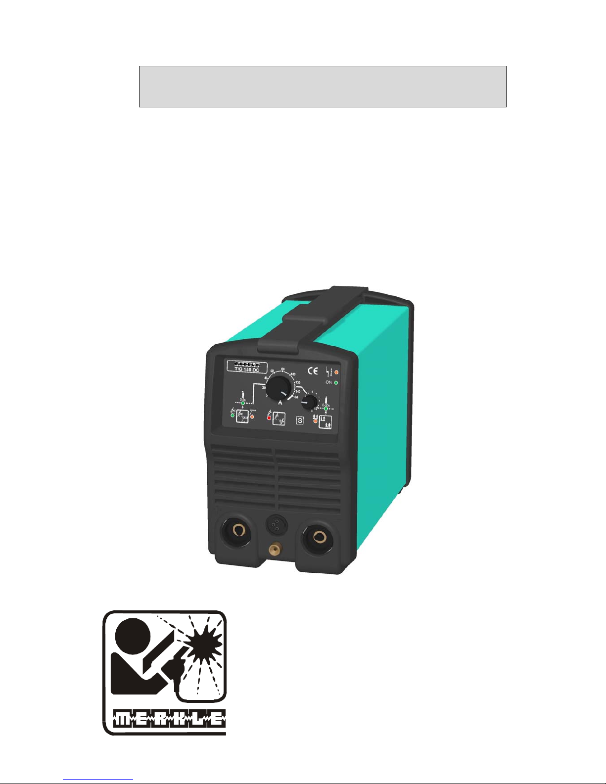
Operation Manual
TIG Welding Unit
Model TIG 160 DC
MERKLE
Schweissanlagen-Technik GmbH
Industriestrasse 3
D-89359 Ko tz, G
Tel.: ++49-8221-915-0
Fax: ++49-8221-915-40
www.merkle.de
eermany

.

Content page
1 Security indications before introduction 2
2 Accident prevention regulations 2
2.1 Safety instructions 2
3 Duty cycle 4
4 Instructions to avoid interferences due to electromagnetic influences EMC 4
5 Technical data: 6
5.1 TIG welding unit, model TIG 160 DC: 6
6 Start Up 7
6.1 Main supply voltage 7
6.2 The earth lead must have an excellent ground. The clamp should be atteched to a clean, paint and
rust free area on the workpiece or on the welding table. 7
7 Operation panel 8
7.1 Front view 9
8 TIG Welding: 10
8.1 Functional diagram of torch trigger 11
8.2 MMA Current Adjusting 12
9 Welding Problems 12
10 TIG hand welding torch - and spare parts 13
10.1 TIG Hand Welding Torch, Model TH 170 G, gas cooled 13
11 Spare parts 17
11.1 Spare parts TIG 160 DC 17
12 Wiring diagram TIG 160 DC 18
13 EU-Conformity Attestation TIG 160 DC 20
1

1 Security indications before introduction
The unit device is built after the recognized standards. Safe works are nevertheless only
possible if you read the operating instructions and the safety regulations contained in it
entirely and obey strictly. Install yourselves by trained staff of our establishments or
appointed dealers.
2 Accident prevention regulations
The following accident prevention regulation is applied for welding unit, model TIG 160DC.
BGV D1 (earlier VBG 15) * Welding, cutting and allied processes.
A copy of this regulation should be readily accessible in every welding shop. The stipulations
of this regulation are to be observed in the interests of safe and correct welding operation.
* Available from the trade association responsible or
Carl Heymanns-Verlag, Luxemburger Strasse 449, 50939 Cologne.
2.1 Safety instructions
This unit is manufactured according to the requirements and stipulations of EN 60974.1 /
VDE 0544 part 1. BGV D1 (earlier VBG 15) of the trade association for precision
engineering and electrical engineering are as well valid.
1) In case of an accident, the cutting unit must be disconnected from the mains
immediately.
2) If electrical contact voltages arise, switch off the unit immediately, disconnect it from
the mains and proceed to inspection by a qualified electrician or by our Service
Department.
3) Before opening the unit, disconnect it from the mains supply.
4) Repair work may only be carried out by a skilled electrician or by our Service
Department.
5) Before the unit is put to operation, check it visually, as well as the torch and all cables
and connectors regarding possible external damages.
6) Personal protective equipment in accordance with DIN EN 175, DIN EN 379 and
DIN EN 169.
During the work, the welder’s body must be completely protected against radiation
and burns by means of protective clothing and face protection. Long gloves, aprons
and welding shields with welding filters conforming to DIN EN 470-1 and BGR 189
must be worn.
Synthetic clothing are excluded. Shoes must be closed, not opened (due to spatters). If
necessary, protective headwear must be worn (e.g. for overhead welding). If cover
glasses are used, these must be in accordance with the norms specified above.
As additional protection for the eyes against UV radiation, safety goggles with side
shields and corresponding face protection in accordance with BGR 192 and BGI 553
must be worn.
Accident prevention regulation BGV D1 § 27 stipulates that it is the responsibility of
the employer to provide suitable personal protective equipment, while § 28 stipulates
that it is the responsibility of the insured to wear suitable clothing.
2

7) Protection when welding under increased electrical risks
Welding rectifiers and welding power sources which can optionally be used for either
direct or alternating current must be marked "S" in accordance with EN 60974-1 and
BGI 534.
Use insulating materials to protect you against contact with electrically conductive
parts and damp floors. Wear dry, undamaged work clothing, long gloves and footwear
with rubber soles. Ventilate rooms, install extraction systems if required, and wear
respiratory protective equipment if necessary (see Procedural instructions BGV D1
§ 27 and BGI 533, Section 5).
8) In order to prevent stray currents and the effects thereof (e.g. destruction of electrical
protective ground conductors), the welding return cable (workpiece cable) must be
connected directly to the workpiece to be welded or to the table (e.g. welding table,
grid-type welding table, workbench) supporting the workpiece (see BGV D1 § 20).
When installing the ground connection, assure that there is a good electrical contact
(remove rust, paint, etc.).
9) During welding pauses, the welding torch is to be laid down on an insulated surface or
hung up in such a way that it is not in contact with the workpiece and its support
connected to the welding power source (see § 20 BGV D1).
In the case of longer work pauses, the welding unit must be switched off and the gas
cylinder valve must be closed.
10) The shielding gas cylinder must always be protected against tumbling downing using a
safety chain.
11) Under no circumstances the unit may be put into operation while it is opened
(e.g. for repair work). Apart from the safety regulations, sufficient cooling of the
electrical components provided by the fan cannot be guaranteed.
12) In accordance with BGV D1 § 5, people in the vicinity of the arc must also be
informed of the hazards and protected against them. Safety partitions (“welding safety
curtains”) must be erected in accordance with DIN EN 1598.
14) N
o welding work may be carried out on containers in which gases, fuels, mineral oils
or similar substances have been stored Öeven if they have been empty for a long
timeÕ (risk of explosion). See § 31 of accident prevention regulation BGV D1.
15) Welds which will be subjected to high loads and which need to meet specific safety
requirements may only be carried out by specially trained and qualified welders.
15) Never bring the torch close to your face.
16) In areas at particularly high risk of fire, the welder must obtain a welding permit and
have this on his person throughout the duration of the welding work. On completion of
welding, a fire-guard must be delegated to ensure fire protection.
17) Ventilation measures must be applied in accordance with BGI 553, Section 9.
18) The hazard to eyesight must be indicated by means of a sign at the work site
"CAUTION! Do not look into the arc!".
3

3 Duty cycle
The duty cylce measurings have been carried out in accordance with
EN 60974-1 / VDE 0544 part 1 (10 min working period).
60% duty cycle means:
After a 6 min. welding period a 4 min welding pause must be respected. The electrical
components are thermally protected against overheating.
4 Instructions to avoid interferences due to electromagnetic influences
EMC
The welding unit has been manufactured in accordance with the requirements of guideline
EN 60974-10 / VDE 0544 part 10 regarding electromagnetic compatibility. It is nonetheless
the responsibility of the user to ensure that the welding equipment is installed and operated in
accordance with the manufacturer’s instructions. If electromagnetic interference is detected, it
is the responsibility of the user of the welding equipment to find a solution with the technical
assistance of the manufacturer. In some cases, it may be sufficient simply to ground the
welding current circuit. In other cases, it may be necessary to build a complete shield for the
welding power source and workpiece using the input filters. In all cases, electromagnetic
interference must be reduced to avoid any possible malfunctions.
Note:
For safety reasons, the welding current circuit may or may not be grounded. No
modifications may be made to the grounding without the approval of an expert who is able to
determine whether the changes might increase the risk of accidents, e.g. by allowing parallel
welding current return paths which could destroy the ground conductors of other equipment.
Further instructions are contained in TEC 974-XX "Arc welding equipment – installation and
use".
a) Evaluation of the installation site
Before installing the welding equipment, the user must evaluate potential
electromagnetic problems in the vicinity. The following must be taken into
consideration:
a. Other power cables, control cables, signal and telecommunication cables above, below
and next to the welding equipment
¾ Radio and television transmitters and receivers
¾ Computers and other control devices
¾ The health of people in the vicinity, e.g. use of heart pacemaker and hearing aids
¾ Calibration and measuring equipment
¾ Interference immunity of other devices in the vicinity. The user must ensure the
electromagnetic compatibility of other devices used in the vicinity. This may require
additional safety measures.
b) Procedures to reduce emitted interference
1) Mains supply
Welding equipment is to be connected to the mains in compliance with the
recommendations of the manufacturer. If interference occurs, it may be necessary to
take additional precautions, e.g. filters for the mains connection. Make sure that the
power cable of welding equipment is installed in a fixed position shielded by means of
a metal conduit or similar. The entire length of the shield must be electrically
connected. The shield must be connected to the welding power source in the way to
obtain a good electrical contact between the metal conduit and the housing of the
welding unit.
4

2) Maintenance of the welding equipment
Welding equipment must be maintained regularly in accordance with the
recommendations of the manufacturer. All access and service doors and covers must
be closed and fastened securely when the welding equipment is in operation. No
modifications whatsoever may be made to welding equipment with the exception of
modifications and adjustments specified in the manufacturer’s operating instructions.
3) Welding cables
Welding cables should be kept as short as possible and routed close together on or
near the floor.
4) Equipotential bonding
It is advisable to interconnect all metallic parts in and next to the welding equipment.
Metallic parts connected to the workpiece can, however, increase the risk of the
welder receiving an electric shock by touching these metallic parts and the electrode
simultaneously. The welder must be electrically insulated against all these connected
metallic parts.
5) Grounding the workpiece
If the workpiece is not connected to the ground for electrical safety reasons, or due to
the size and position of the workpiece, e.g. steel structure or outer wall of a ship,
grounding the workpiece may in some cases, but not all, reduce emitted interference. It
must be ensured that grounding the workpiece will not increase the risk of accidents
for the user and cannot cause the destruction of other electrical equipment. If
necessary, the grounding of the workpiece must be carried out by means of a direct
connection to the workpiece. In countries where a direct connection is prohibited, the
connection must be made by means of suitable reactors, selected in accordance with
national regulations.
6) Shielding
Selective shielding of other cables and devices in the vicinity can reduce interference
problems. For special applications, it may be worth considering shielding the entire
welding system.
5

5 Technical data:
5.1 TIG welding unit, model TIG 160 DC:
Primary:
Voltage: 1x230 V (240 V)
Frequency: 50/60 Hz
Cont. power (TIG/MMA): 2.2 / 3.7 kVA
Cont. current (TIG/MMA): 9.4 / 16 A
cos phi: 0.98
Secondary:
Open circuit voltage: 80 V
Welding voltage: 10-16 V
Welding current: 3-155 A
Duty cycle 35 % : 155 A (25 °C)
Duty cycle 60 % : 130 A (25 °C)
Duty cycle 100 % : 115 A (25 °C)
MMA/stick electrode operation:
Stick electrode: 1.5-3.25 mm
Open circuit voltage: 80 V
Welding voltage: 20-26 V
Welding current: 3-150 A
Protection class: IP 23
Isolation class: H
Cooling: AF
Main switch: 2-phase
Mode: TIG/MMA-welding
Operation modes: 2-stroke/4-stroke
TIG ignition: HF-/lift-arc
Potentiometer: welding current
Potentiometer: down slope,
gas post flow time
integrated function: arc force
Socket: remote control
LED: mains ON
LED: temperature protection
Current source: inverter
Operation tem.: down to -20°C
Norm: EN 60974-1 "S" / CE
Torch connetion: single connector
and 5-pole ADM plug
Cooling torch: gas
Socket 25 mm²: earth lead
Socket 25 mm²: electrode welding cable
Mains supply cable: 3 x 2.5 mm², 2.5 m long
Gas connection: pluggable NW 2.7
Weight: 7 kg
Dimensions L x W x H: 325 x 152 x 235 mm
6

Standard accessories
Earth lead 16 mm², 4 m long 022.1.0386
with plug 25 mm² and earth clamp
Regulator argon/CO2 107.018
standard version
Gas hose 2 m long, 107.984
with 2 screw connectors 1/4"
6 Start Up
Installation of the machine
Place the machine at least 0.80 m from a wall etc. to guarantee the cooling air can go through
the unit. The room temperature should not exceed 40°C.
6.1 Main supply voltage
The main supply must be connected by a trained person. The main supply voltage is displayed
on a sticker at the machine. The protection earth must be connected.
Earth lead (work cable) and stick electrode welding cable
6.2 The earth lead must have an excellent ground. The clamp should be atteched to a
clean, paint and rust free area on the workpiece or on the welding table.
Maintenance
The maintenance of the welding machine consists of a regular cleaning and inspection. It
depends on the enviroment of the working area and the working hours.
Operation at generators
The genarator must supply at least 10 % more power than the maximum power requirement
of the welding unit. Switch on the welding unit after the generator has been switched on.
7

7 Operation panel
12
13
14
17 11 10
9
8
7
15 16
8

7.1 Front view
5
6
9

8 TIG Welding:
Connect earth lead to socket (Pos.3).
Connect the torch lead to the negative polarity socket (Pos.6).
Connect the gas hose to the gas outlet at the front and at the rear.
Switch on main switch at the rear panel, LED (Pos.13) goes on. Press button (Pos. 9) for TIG
welding, LED (Pos. 8) goes on. Adjust the welding current at potentiometer (Pos.1). Select
(Pos. 17) HF or lift arc ignition. HF-ignition will be indicated by LED (Pos. 11). Select (Pos.
15) 2- or 4-stroke operation. LED (Pos.16) is on when 4-stroke operation is selected.
Adjustment of gas pre flow time:
Press down button (Pos. 9) and wait until LED (Pos.7) flashes. Keep button (Pos.9) pressed
down and adjust gas pre flow time 0 .. 5 s at potentiometer (Pos. 1).
Adjustment of gas post flow time:
Press down button (Pos. 15) and wait until LED (Pos.14) flashes. Keep button (Pos.15)
pressed down and adjust gas post flow time 0 .. 20 s at potentiometer (Pos. 1).
Lift arc ignition
Select at button (Pos. 15) 2- or 4-stroke operation.
Adjust the welding current at potentiometer (Pos.1).
Place the tungsten electrode to the work piece an press down th e torch switch. Lift the torch.
The current can be adjusted at potentiometer (Pos 1).
Attention: Switching off the unit while welding will destroy the main switch!
You can connect a foot remote control to socket (Pos. 2). The current, adjusted at the
potentiometer (Pos.1), will limit the max. welding current.
If there is a thermical overload LED (Pos.12) will go on.
10

8.1 Functional diagram of torch trigger
2-stroke mode
Schweißstrom 1 Gasvorströmen
Welding current Down-slope Down-slope Pre-gas
1 2 1 2 2 Gasnachstömen
Post-gas
Gas
Brennertaster / Torch-trigger
2-stroke mode with short interruption
Schweißstrom 1 Gasvorströmen
Welding current Down-slope Pre-gas
1 2 2 2 Gasnachstömen
Post-gas
Gas
Brennertaster / Torch-trigger
4-strokes mode
Schweißstrom 1 Gasvorströmen
Welding current Down-slope Pre-gas
1 2 2 Gasnachstömen
Post-gas
Gas
Brennertaster / Torch-trigger
11

Operation outside the workshop
The unit can be placed and operated outside the workshop according to the protection class
IP 23. Make sure that all electrical parts are well protected against rain and water.
8.2 MMA Current Adjusting
The welding current depends on the stick electrode and the diameter.
Diameter stick electrode (mm) 1.5 2.0 2.5 3.25
Welding current (A) 40-60 40-80 60-100 90-150
For exact values see the manuel of the stick electrodes.
9 Welding Problems
Problem Reason
weld is too high - pre heating not sufficient
- welding current too low (aprox.:
current = 30...40 x material thickness
- welding speed is too high
weld is too low - welding current too high
- welding speed is too low
low penetration of the weld - wrong geometry of the work pieces
- arc is too long
- welding speed is too high
- pre heating is necessary
weld is falling through - distance between work pieces is too big
- welding current is too high
- arc is too short
- welding speed is too low
Trouble Shooting
Control lamp at the main - no supply voltage
switch do not go on - check fuses
- interuption of mains supply cable
or fault of the main switch
Control lamp „Thermi. Protection - inverter temperature too high
goes on leave machine switched on, fan will cool down
the unit
12

10 TIG hand welding torch - and spare parts
for torch model TH 170 G, gas cooled - with single connection, for TIG 160 DC,
„Quick TIG System”
10.1 TIG Hand Welding Torch, Model TH 170 G, gas cooled
Technical data:
Cooling: gascooled
DC range: 150 A, 40 % ED
AC range: 130 A, 40 % ED
Electrodes: 1.0 – 2.4 mm ∅
Weight: 240 g
without cable assembly
13

TIG Hand Welding Torch, Model TH 170 G, gas cooled
14

TIG Hand Welding Torch, Model TH 170 G, gas cooled,
Single Connection (TIG 160 DC)
Pos. Description Part No._
TIG hand welding torch 107.546
model TH 170 G, 4 m
with connector for TIG 160 DC
TIG hand welding torch 107.547
model TH 170 G, 8 m
with connector for TIG 160 DC
Standard equipment: 1,6 mm, ceramic 10
Spare parts and consumables:
Pos. Description Part No._
3.1 Tungsten-electrode, grey min 10 pcs 013.0.0111
1.0 x 175 mm
3.2 Tungsten-electrode, grey min 10 pcs 013.0.0112
1.6 x 175 mm
3.3 Tungsten-electrode, grey min 10 pcs 013.0.0113
2.4 x 175 mm
8.1 Back cap "quick TIG" 1.0 mm, long 106.850
TH 170/250 G, TH 450 W
8.2 Back cap "quick TIG" 1.6 mm, long 106.854
TH 170/250 G, TH 450 W
8.3 Back cap "quick TIG" 2.4 mm, long 106.856
TH 170/250 G, TH 450 W
9.1 Back cap "quick TIG" 1.0 mm, short 107.684
TH 170/250 G, TH/TM 450 W
9.2 Back cap "quick TIG" 1.6 mm, short 107.686
TH 170/250 G, TH/TM 450 W
9.3 Back cap "quick TIG" 2.4 mm, short 107.688
TH 170/250 G, TH/TM 450 W
10 Torch neck TH 170/250 G 106.864
11 O ring 9 x 1.5 022.1.0704
12.1 Ceramic nozzle 6.5 min 10 pcs 104.260
TH 170/250 G, TH 450 W
12.2 Ceramic nozzle 8.0 min 10 pcs 104.262
TH 170/250 G, TH 450 W
12.3 Ceramic nozzle 10.0 min 10 pcs 104.264
TH 170/250 G, TH 450 W
12.4 Ceramic nozzle 12.5 min 10 pcs 104.266
TH 170/250 G, TH 450 W
Options for gas lense operation:
13.1 Gas lense 1.6 mm TH 170/250 G, 110.956
TH 450 W
15

Pos. Description Part No._
13.2 Gas lense 2.4 mm TH 170/250 G, 110.958
TH 450 W
14.1 Ceramic nozzle, heavy duty, size 4 013.7.0035
14.2 Ceramic nozzle, heavy duty, size 5 013.7.0036
14.3 Ceramic nozzle, heavy duty, size 6 013.7.0037
14.4 Ceramic nozzle, heavy duty, size 7 013.7.0038
14.5 Ceramic nozzle, heavy duty, size 8 013.7.0039
14.6 Ceramic nozzle, heavy duty, size 10 013.7.0040
33 pc board for TIG double button 107.992
switch (for torch with ball joint)
34 Switch button (red) min 10 pcs 107.994
for TIG torch with ball joint
35 Handle TIG torch, right and left 107.988
side (delivered without ball joint)
37 Ball joint for TIG torch handle 107.996
gas cooled incl. fixture nut
51 Control cable 3 x 0.5 LiYY min 50 m 107.646
no shield
51 Control cable 3 x 0.5 LiYY 107.646
no shield
61 Protection hose leather, 107.648
22 mm, black
66.1 Cable assembly TH 170 G, 4 m 107.853
incl. 3 x 0.5 cable
66.2 Cable assembly TH 170 G, 8 m 107.854
incl. 3 x 0.5 cable
67 Copper cable isolated 16 mm² 107.820
high flexible (for TH 170 G)
68 Tube 10 mm cpl. with nut M 16 107.852
and Cu tube brazed (TH 170 G)
69 Gas hose 4.5 x 1.3 high flexible 107.972
70 Quick connector 2.7 for gas hose 108.002
71 Plug 25 mm² 012.0.1501
72 Round plug ADM (small) 5-pole 107.842
for TIG torches
16

11 Spare parts
11.1 Spare parts TIG 160 DC
Pos. description electr. part no.
1 plastic front 108.160
2 plastic back 108.158
3 bottom 108.162
4 cover 108.628
5 gas valve 230 V Y1 002.0.1601
6 mainswitch wich control lamp Q1 001.0.0027
7 socket ADM 5-pol X2 107.974
8 pcb inverter 301 C A1 108.164
wich pcb logik 301 C-FS
9 fan 230 V/AC M1 001.0.1320
10 choke TIG 160DC L1 108.144
11 front panel wich touch switches 108.174
12 pcb front 308 A-FS A2 108.166
incl potentiometers
13 knob 14 mm 108.168
14 knob 23 mm 108.150
15 gas connection torch side 108.170
16 transport belt 108.152
17 fixture for main supply cable 108.154
17

without figure:
socket 25 mm² 012.0.1506
main supply cable 3 x 2,5 mm², 007.0.1142
temperature switch sec. 80° opening F1 108.202
accessories:
plug Schuko X1 012.0.1950
12 Wiring diagram TIG 160 DC
18

1 2 3 4 5 6 7 8
2
1
2
1
654321
-L1
-X3
-X2
54321
-M1
Lüfter/fan
220-240V
1,4A
?U/min
-Y1
-X1
L1
N
PE
-Q1
A1
B4
A2
B5
-A2
TIG 150 DC
A
0 10
5
3
40
40
80
100
120
140
150
Platine 308A-FS
-A1
+
J9
ge
gn
LED1
LED2
10
J4
1
1 2 3 4 5 6
J3
Platine 306C-FC
Platine 301C-FC
J8
J3
J5
J2
J6
J10
1
-F1
ge-gn
gn
ge
or
rt
bn
ge-gn
bl
vio
vio
sw
sw
ge-gn
bl
sw
bn
sw
bn
rt
or
ge
gn
Elektrode
stick electrode
Flachbandkabel
flat band cable
+
Werkstück
work piece
EAD
B
C
1
2
BT.
Fußfernregler
foot remote control
Brennertaster
torch switch
oder/
or
M
1~
Gasventil
gas valve
1PH-230/240V/50-60Hz/N/PE
E A
Blatt
1
Bl.
1
Projektbez.
Auftragsnr.
Zeichnungsnr.
TIG160DC
Änderung
Datum
gez.
gepr.
Name
Datum
Name
Konrad
06.10.03
Stromlaufplan
Vervielfältigung oder Weitergabe nur mit unserer schriftlichen Genehmigung gestattet
c
dab
Plotdatum:
13.05.04
Merkle
Schweißanlagen-Technik GmbH
Industriestraße 3
D - 89359 Kötz
Telefon 08221 -915 - 0
Telefax 08221 - 32596
=
+
SQ

13 EU-Conformity Attestation TIG 160 DC
EU – Conformity Attestation
Description of the unit: TIG Welding Unit
Model: TIG 160 DC
The above mentionned unit complies with the following European Regulations:
EU-Low Voltage Regulation 73/23/EWG
EU-Electromagnetic Compatibility 89/336/EWG
In case of any modifications, incorrect repairs not exclusively authorized by Merkle, this
attestation looses its valdity.
Applied norms EN 60974 - 1 / IEC 974 - 1 / VDE 0544 part 1
EN 60204 - 1 / IEC 204 - 1 / VDE 0113 part 1
EN 60974-10 / VDE 0544 Teil 10
Kötz, April 14th, 2004
Wilhelm Merkle, Generalmanager
Merkle Schweissanlagen-Technik GmbH
20

Notes:
21

M E R K L E
Schweissanlagen-Technik GmbH
MERKLE
Schweissanlagen-Technik GmbH
Industriestrasse 3
D-89359 Koetz,
Tel.: ++49-8221-915-0
Fax: ++49-8221-915-40
www.merkle.de
Germany
1. Edition 2004 September 24th.2004
Technical changes reserved
22
 Loading...