


Service-Instructions PU 520 DW
with pcb RPM-control ME-2QR-24/42-2.1
02.07.2003
1) Clean the machine and watch out for external damages (painting, front panel).
2) Visual check:
- First check: measurings according to EN 60204 / VDE 0113/ VDE 0701
Cabels, connectors and screw contacts: check well placed cables and save fixings;
Cables for voltage measuring – the minuspole of the choke must be mounted in the direction
of the bush mass cable; cover at the main switch;
Check if the fixing feet of the pcbs are screwed tight;
Check if the pcb MTC-1.2 is screwed with metal supports M3 and on its top
fixed with springs;
Check if the 10-pol. flat cable between pcb ME-MTC-1.2 and ME-2QR-24/42-2.1
goes under pcb ME-MTC-1.2;
Pcb ME-I-SD-1.1: check bridge at connector X5/1-10 ;
Clean the unit, check the contacts of the pcbs (free of vernis)
Check serial number, sticker with date on the pcbs;
Disconnect
all pcb connectors (except flat cables) !
PAL MTC 2 on pcb ME-MTC-1.2
E-Prom: MTC 1.82 / 29.06.1999 // PU 500 1.73 / 26.04.2000
Check the jumpers:
Pcb ME-I-SD-1.1:
X4/6-8 placed
JP1 placed
JP2 MAG
JP3 placed
JP4 intern
JP5 placed
Bridges closed and brazed
Pcb: ME-MTC/M-2.0: ME-PPMR-2.1:
JP1 PU 500 JP1 placed
P2 opened JP2(<3m) placed
Pcb ME-2QR-24/42-2.1)
Jumper (DV25 and DV30) set acc. wiring diagram
At the pcb 2QR-24/42 in connection with the DV30 a capacitor 0,1 uF,1000V between
clamps 5 and 6 must be parallely mounted to avoid interferences with the tacho;
Check the polarity of the connection to rectifier, cascade, capacitors.
Have a look at the distance of the cable shoes between steel plates and main
transformer/cascade;
1
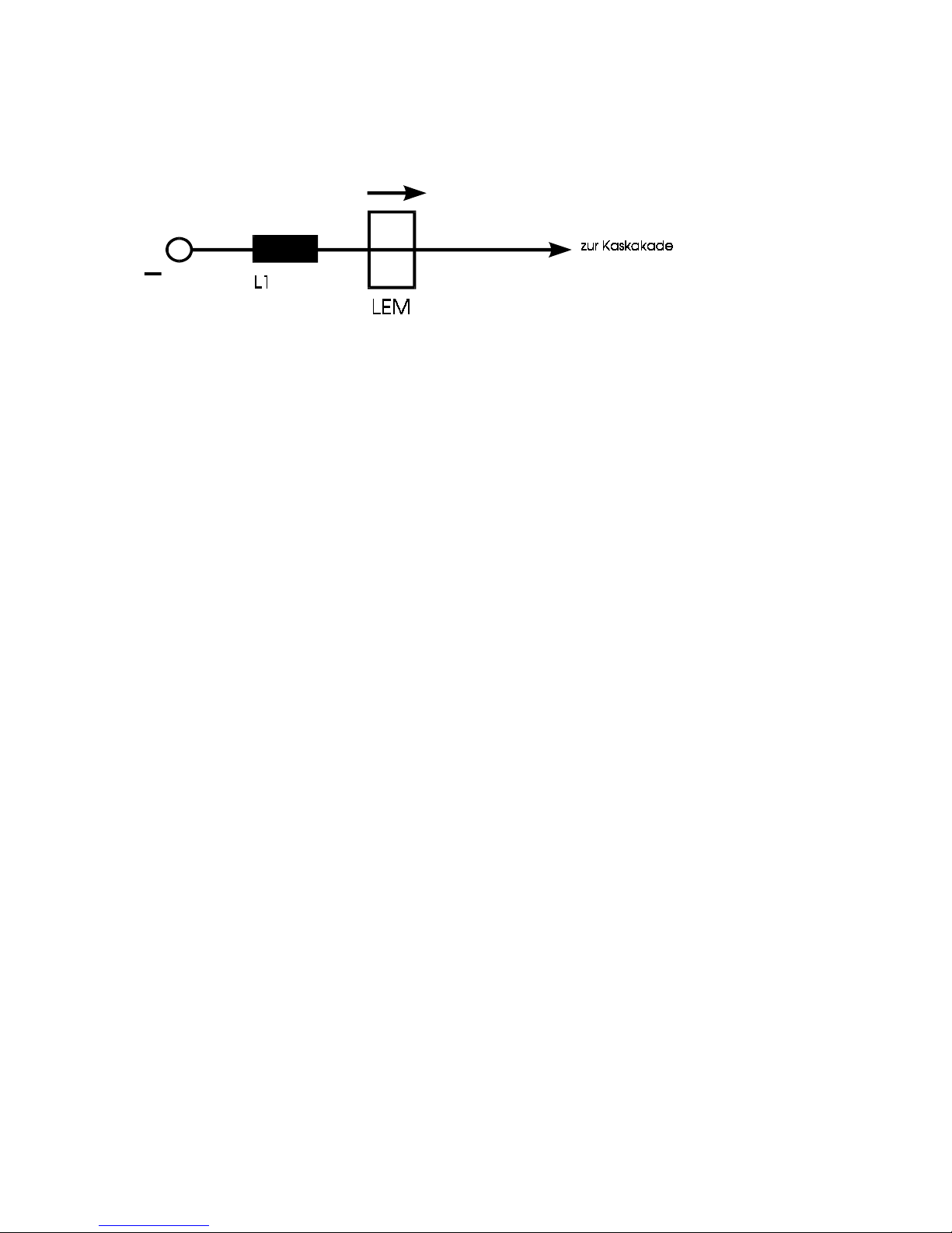
Check the direction of the current cable before you introduce it into the current
transformer LEM
Check tight connection of the primary at the main transformer;
Check capacitors at the plus- and minus-bush:
0,1 uF/1000V plus-bush Ö minus-bush
0,1 uF/1000V plus-bush Ö housing,
0,1 uF/1000V minus-bush Ö housing,
Fan must turn freely;
3) Measurings of the voltages:
Switch ON machine;
F1 – F2 (0-400V at control transformer) 400 V AC
Pcb RPM control ME-2QR24/42-2.1:
A6 – X1/3, X1/4 42 V AC
Pcb ME-I-SD-1.1:
A1 - X6/1, X6/2 18 V AC
A1 - X6/5, X6/6 18 V AC
A1 - X6/3, X6/4 9 V AC
A1 - X5/1, X5/2 9 V AC
A1 - X8/11, X8/12 42 V AC
A1 - X9/1, X9/2 230 V AC
Pcb ME-I-SD/K-1.1:
A2 - X3a/1, X3a/2 18 V AC
Pcb ME-MTC-1.2:
A3 - X1/1, X1/2 9 V AC
A3 - X1/3, X1/4 18 V AC
Pcb ME-PPMR-2.1:
A7 - X2/5, X2/6 42 V AC
Main rectifier:
Entrance 3 x 56 V AC
Exit app. 78 V DC
Entrance cascade app. 78 V DC
2

Pcb ME-I-SD-1.1:
Measure NTC resistors between
A1 - X5/3, X5/4 app. 75...125 kOhm
A1 - X5/5, X5/6 app. 30... 75 kOhm
Switch OFF unit
4) Connect the wire feeder and clean it
Have a look at the distance between front plate and plus cable;
Connect supply and mass cable;
Disconnect coupling of waterflow = deaeration of the water pump;
fill the cooling liquid into the cooling system;
Connect the TEDAC-torch;
5) Plug in connectors to the pcbs;
Switch ON unit
Check the direction of the waterflow;
Check fan:
Fan is turning with a reduced speed;
Bridge on pcb ME-I-SD-1.1 A1-X5/3-4: fan is turning with max. speed
Bridge on pcb ME-I-SD-1.1 A1-X5/5-6: fan is turning with max. speed;
The following LEDs are enlighted:
At pcb ME-I-SD-1.1
After main switch on
green +5V – supply voltage
green +15V – supply voltage
green -15V – supply voltage
green +15VP – control voltage (FET-control-transistor cascade)
LED after torch trigger pressed or mode electrode:
red - Start (torch trigger pressed or mode electrode)
green – PWM ON control (20 KHz-pulse modulation)
yellow - relais GAS – gasvalve on
green – relais Lüfter – fan (Inverter) running
green – relais waterpump / fan (torchcooling) running
LED after arc on
red -I>0 (when the arc is on)
red - relais I>0 Rel. potential free contact is switched
Gas Rel. (torch trigger pressed)
Fan Rel.(when the arc is on)
Waterpump Rel. (when the arc is on Ö cuts after app. 5min.)
LED when failure
red - Stoer. =General failure-LED ON in connection with:
red - Uebert (OVERHEATING) – unit is dirty or the duty cycle has been passed, or
3

red - Uebersp (OVERVOLTAGE)- supply voltage higher than 440 VAC, or
red - Unterspg (UNDERVOLTAGE)- supply voltage lower than 360 VAC
red - WD fehlt (WATER PRESSURE MISSING)- unit in standby-mode, cooling liquid
missing,
Flow sensor does not work or low water switch defective
LED in connection with LED Übertemp (OVERTEMP):(row: red,yellow, red,yellow)
red - UeI ( OVERTEMP 70°C) at the cooling body prim.-IGBT
red - UeT (OVERTEMP 150°C) at the transformer
yellow - LI (OVERTEMP ) – temperature at the cooling body prim.-IGBT still over 50°C
Ö fans must still run
yellow - LT (OVERTEMP)- at the transformer still over 80°C
Ö fans must still run
other LEDs
red - Idyn (CURRENT LIMITATION SEC.) appr. 600 A
yellow - Istat CURRENT LIMITATION SEC.) appr. 420 A
At pcb ME-2QR-24/42-2.1
Torch trigger on
green – FRG (free)
Torch trigger off, wire feeder motor – stop
yellow - brake enlightened shortly ; LED "Frg" off
Main switch off;
Plug in connector to the current transformer LEM;
6) Adjusting pcb RPM control:
6.1) Adjusting without supplementary device:
main switch ON
Setting on the unit:
Display-indication V , Pulse, setting of the energy at the wire feeder, 1.2mm
∅
, 4-stroke,
material 1= SG2+3
Poti energy = 50%, poti voltage = max. turn to the left
4

At the pcb RPM control ME-2QR-24/42-2.1: bridge jumper to DV 30
m
max
min
Bremse
Freigabe
Drehzahl
DV 30
JP1 opened
JP2 placed middle-extern
JP3 placed middle -extern
JP4 placed middle –extern
Main switch ON
Program mode:
Ö
Press botton Gas and pull back TEDAC-slide switch app. 5sec
Turn poti voltage until the upper display shows „dF“
Move TEDAC-slide switch until the other display shows „0“
Turn poti voltage until the upper display shows „dr“
Adjust with TEDAC-slide switch until the other display shows 3.0 = 3,0 m/min.
Press torch trigger
If the wire feeding motor does not run constantly but in the right direction, change the
tacho connector inside the wire feeder (cl.5 and cl.6
Ö
yellow wires);
If the motor is running in the wrong direction check the cables of the anchor;
If the motor is correctly connected, it can be adjusted with the poti energy or with TEDAC ,
If the motor is adjustable but turning to the wrong direction, the connection of the tacho and
the anchor must be changed
Turning direction of the motor axe: right
LED at pcb ME-2QR-24/42-2.1
Torch trigger ON: LED "Frg" (Free green) enlightened;
Torch trigger OFF: LED "B" (Brakes yellow) enlightened shortly; LED "Frg" off;
Ö
Short circuit between contact tip and work pieceÕ
Torch trigger ON
Mesure with a multimeter at pcb ME-2QR-24/42-2.1 on X3/ 1 (GND) X3/ 4 (+)
app.1,2V,
DV30: Tacho voltage on pcb ME-2QR-24/42-2.1:
X1 - 5-6 adjust to app. 2,93V-DC with trimmer “min”
5

Torch trigger OFF
Take away the contact tip from the work piece
Display switches back to „dr 3.0“after 10 sec.
Adjust RPM to the max. with TEDAC slide switch (Display 29,9 = 29,9 m/min.),
Ö
Short circuit between contact tip and work pieceÕ
Torch trigger ON
DV30: Tacho voltage at pcb ME-2QR-24/42-2.1:
X1 - 5-6 adjust to app. 29,3V-DC with trimmer “max”
Torch trigger OFF
Take away the contact tip from the work piece
Effective value=min. and max: check again the adjustings;
Adjust with TEDAC to the RPM min. (Display 00,0) and check if the motor stops.
Main switch OFFÖ DV-Testprogramm will be canceled
Main switch ON Ö Programm from the E-Prom will be loaded
6.2). RPM setting with a supplementary device: part-no. 104.156
Disconnect the flat cable from the pcb ME-2QR-24/42-2.1 plug in the connector of the
supplementary device at connector X3.
DV 30
„Usoll 1V“ free ON
⇔
adjust tacho voltage at X1 – 5-6 on app. 2,5V-DC with trimmer
“min” free OFF
„Usoll 10V“ free ON ⇔ adjust tacho voltage at X1 – 5-6 on app. 25,1V-DC with trimmer
“max” . Free OFF
Check again adjusting „Usoll 1V“
6.3) Current adjusting at the LEM current transformer
Mode Pulse:
Program mode:
Press green botton gas check and pull back the TEDAC-slide switch for app. 5sec.
Setting of the poti „arc voltage“and TEDAC to the following values:
IG 490A
IP 510A
tp 4,00ms
F 150Hz
SAn 3
SAb 4
Ur xxx
dF 0
dr xxx
rb xxx
I xxx
U xxx
d xxx
6

Adjusting of zero at the current transformer LEM:
Multimeter to be clamped to ME-I-SD-1.1 M0(-) und M6(+), range 300mV;
Adjust with trimmer P1 at the LEM to 0.0V +/-10mV ;
Adjusting of the max. at the LEM / check polarity:
Make a short circuit with a shunt between bush electrode and work piece
Measure current with the shunt
Press the torch trigger
Adjust with trimmer P2 at the LEM to 500A +/-3A
Press the torch trigger;
Main switch OFF;
7) Equip wire feed system with rollers St 1,2mm
Introduce and adjust rollers and assure straight line with the existing tubes;
Adjust pressure of the upper rollers (The feeding of the wire must be constant without any
sliding);
Press botton“wire curentless“ when adjusting the pressure;
Check the brake of the wire coil support, if necessary use grease
8) Connect gas hose- check gas-tightness;
Main switch ON;
Mode "Pulse", put selector for material and wire diameter in position 1=SG2+3, 1.2mm ∅;
Function "Special 4-stroke"; adjusting on"TEDAC";
Put digital read-out on 200A
Keep the torch trigger pressed in no load mode - Istart-Display must show appr. 250A +-10A,
if necessary adjust with trimmer "Startstrom"(START CURRENT) at pcb ME-MTC-/MF-1.3;
Release torch trigger and press again – Digital read-out has to go down to appr. 60 A, if
necessary adjust with trimmer "Endstrom" (FINAL CURRENT) at pcb ME-MTC-/MF-1.3;
Adjust the down slope time to appr. 1s, (use trimmer "Absenkzeit" (DOWNSLOPE TIME)
at pcb ME-MTC-/MF-1.3;
If meanwhile the safety cut off divice is activated, repeat procedure;
Weld using the full welding range.
7

The wire burn back can be adjusted by the trimmer "Rückbrand" (WIRE BURN BACK) at
pcb ME-MTC-/MF-1.3).
9). Adjustings of the Digital Read Out (Volts)
¾
Umin:
Pcb MTC/M 2.0 – M0 against Um with „Trimmer U0“ adjust on -25...30 mV
¾
Umax:
measure the no load voltage:
Multimeter at plus- and minus- bush
Switch to mode „ELECTRODE“
Measure appr. 70 V DC; the indicated voltage at the read-out can be adjusted with
„Trimmer UM“ on the measured value appr. 70V DC ,
Switch to „PULSE-ARC“, no voltage to be measured;
!!!!! Check the right polarity !!!!!
¾
Indication of current in Pulse Arc Welding:
Adjust with trimmer „I0“ min (app.30% Energy) and
max with trimmer „Im“ (at app.70% Energy).
(Measure the welding current with an external shunt).
Check the values of the display at position „Energy min.“
Check function of the poti voltage trim:
Left (--> -30%) welding arc gets shorter;
Right (-->+30%) welding arc gets longer
check function of intermission- and spot welding:
Check function of the poti welding time (0.5 to 2.5s);
Time for pause (=programmed value)
Mode MIG/MAG:
weld using the full current range and check the function of the poti voltage trim;
10) Remote cotrol for energy and voltage trim:
The two potis „energy and voltage trim” are concerned.
The full range can be adjusted by external potis;
The position of the two potis at the wire feeder is insignificant.
All trimmers to be sealed with vernis.
When checking, note failures, their cause and their reparation !
8

Trouble shooting for PU 400/500/520
(Supplement to the users manual)
Troubles
Causes / Help
green LED for mains is not enlighted af main swith
ON
- one or several phases missing
- mains connector wrong connected
- defective fuses at the control transformer
- pcb ME-MTC-1.2 defective
- pcb ME-MF-1.3 defective
Waterpump is running all the time after main switch
ON and red LED (failure) is enlighted
- waterpressure missing or or waterpressure
switch defective
- the following LEDs must be enlighted
at the pcb ME-I-SD-1.1:
WDfehlt (waterpressure missing, red)
Wasserp.(waterpump,green)
no load voltage missing
- TEDAC-torch defective
- pcb ME-MTC-1.2 defective or
- pcb ME-MTC/M-2.0 defective
(Access to the pcbs is possible after lifting the
cover of the housing)
The following LEDs must be enlighted at the pcb
ME-I-SD-1.1 :
+15V, -15V, +5V,
torch trigger pressed: +15VP, PWM-ON (green LED
beside the cooling body),
start (red), gasrelais (yellow)
- on pcb ME-I-PG-1.0 (only PU400)
Attention! supply voltage !
the green LED must be enlighted
no welding current
- mass cable connected to bush electrode
- water current cable defecktive
- pcb ME-MTC-1.2 defective+
9

yellow LED overtemperature and red LED failure
enlighted
- overtemperature transformer or cooling body:
let cool the machine
- pcb ME-I-SD-1.1: indicated by LEDs:
UeI (red: overtemp. at the cooling body)
LI (yellow fan/cooling body)
UeT (red: overtemp transformer)
LT (yellow fan/transformer)
In the following cases the inverter has to be
substituted (ONLY PU 400)
- if LEDs UeI (red) and LI (yellow) are ON
- cold unit – the thermic sensor (NTC) on the cooling
block has got a short circuit
if LEDs UeT (red) and LT (yellow) are ON- cold unit
the thermic sensor (NTC) on the main transformer
has got a short circuit
- if LED UeI (red) is ON but LED LI (yellow) is OFF,
the thermic sensor (NTC) on the cooling block is interrupted
if LED UeT (red) is ON but LED LT (yellow) is OFF,
the thermic sensor (NTC) on the main transformer is
interrupted
LED failure (red) enlighted
PU400:
- Safety cut off circuit of continous over current
activated:
Pcb ME-I-PG-1.0: red LED enlighted
Switch off main switch. After >3s switch on again
bad welding results wrong program selected or wrong adjusting of the
voltage trim
- pcb ME-MTC-1.2 or ME-MTC/M-2.0 defective
- LEM-current transformer defective
- pcb ME-ISD-1.1 defective
10
 Loading...